

Page 1
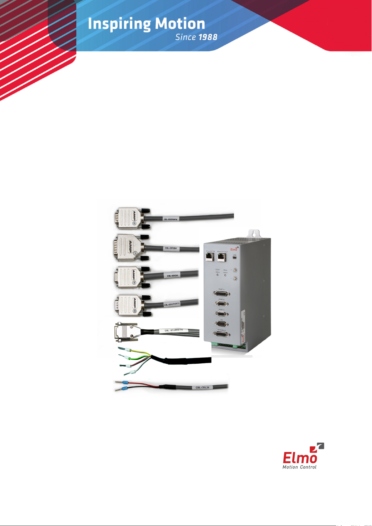
Gold Tuba
Gold Tuba Cable Kit
(EtherCAT and CAN)
February 2014 (Ver. 1.000) www.elmomc.com
Page 2

Notice
This guide is delivered subject to the following conditions and restrictions:
• This guide contains proprietary information belonging to Elmo Motion Control Ltd. Such
information is supplied solely for the purpose of assisting users of the Gold Tuba servo drive in
its installation.
• The text and graphics included in this manual are for the purpose of illustration and reference
only. The specifications on which they are based are subject to change without notice.
• Information in this document is subject to change without notice.
Document no. MAN-G-TUB-CBLKIT (Ver. 1.000)
Copyright 2014
Elmo Motion Control Ltd.
All rights reserved.
Catalog Number
CBL-GTUBCCKIT
Revision History
Version Date Details
Ver. 1.000 February 2014 Initial release
www.elmomc.com
Page 3

Table of Contents
Table of Contents
MAN-G-TUB-CBLK IT (Ver. 1.000)
Chapter 1: Introduction .................................................................................................... 4
1.1. Cable Kit (CBL-GTUBCCKIT) ............................................................................................. 4
Chapter 2: Port A Cable .................................................................................................... 5
Chapter 3: Port B Cable .................................................................................................... 7
Chapter 4: Port C Cable .................................................................................................... 9
Chapter 5: I/O Cable ....................................................................................................... 11
Chapter 6: Network I/O Cable......................................................................................... 13
Chapter 7: STO Cable ...................................................................................................... 16
Chapter 8: 24 VDC Auxiliary Supply ................................................................................. 18
3
Chapter 9: CAN Terminator ............................................................................................ 19
www.elmomc.com
Page 4
Gold Tuba Cable Kit (EtherCAT and CAN)
Chapter 1: Introduction
MAN-G-TUB-CBLK IT (Ver. 1.000)
This document provides the wiring details for the cables used to connect Elmo's Gold Tuba
servo drive with the end-user application. The servo drive-front pinouts are provided in the
Gold Tuba Digital Servo Drive Installation Guide.
The cables come in one length: 2 meters (6 ½ feet).
1.1. Cable Kit (CBL-GTUBCCKIT)
NOTE:
It should be noted that this kit does not include any CAT5E RJ-45 for EtherCAT/CAN and MiniUSB communication cables. Please purchase these cables separately. These items are standard
cables that can be purchased locally.
4
The CBL-GTUBCCKIT cable kit includes the following cables:
Function Description
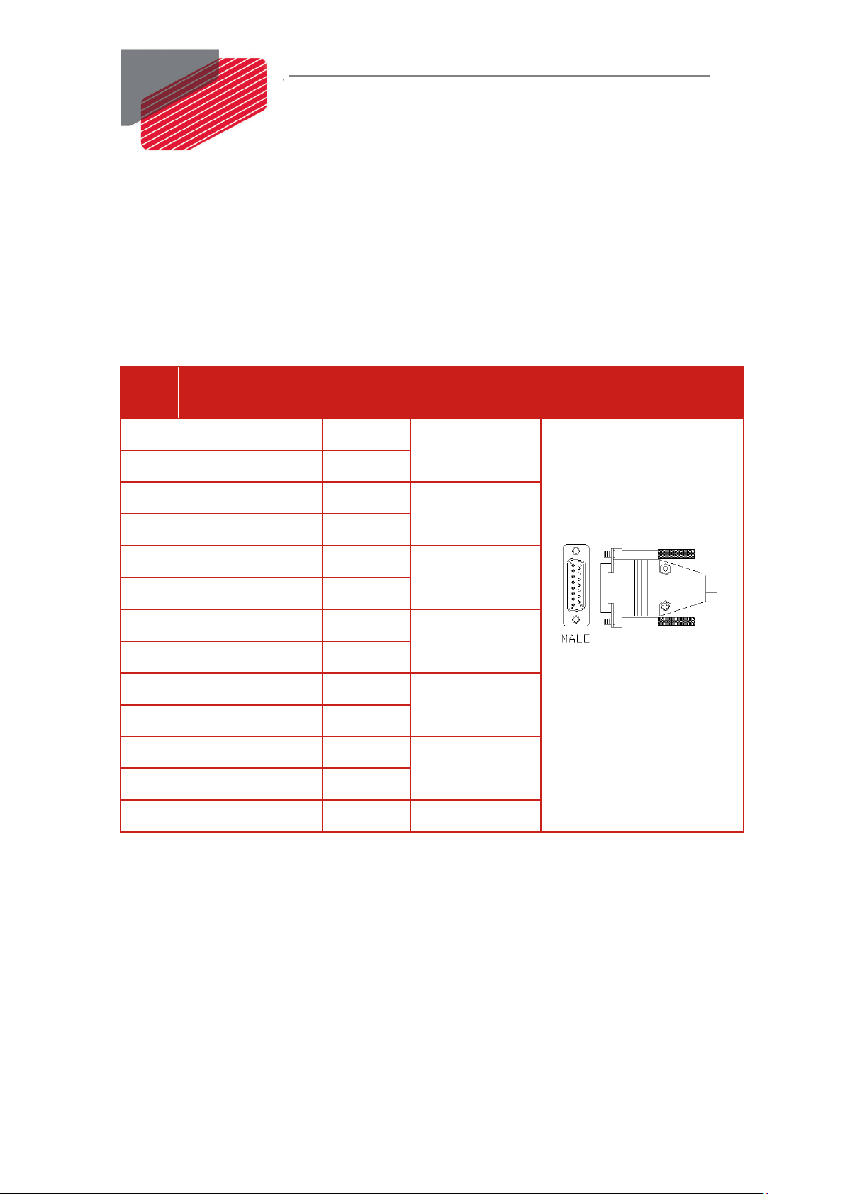
Port A cable 15-Pin D Type Male connector
Port B cable 9-Pin D Type Male connector
Port C cable 15-Pin High Density D Type Male connector
I/O cable 15-Pin High Density D-Type Female connector
Network I/O cable 26-Pin High Density D-Type Male connector
STO cable 4-Pin Phoenix Plug-in connector
24 VDC auxiliary supply 2-Pin Phoenix Plug-in connector
www.elmomc.com
Page 5
Gold Tuba Cable Kit (EtherCAT and CAN)
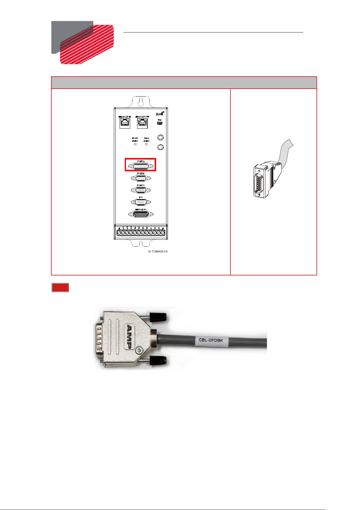
Chapter 2: Port A Cable
MAN-G-TUB-CBLK IT (Ver. 1.000)
The Port A cable is a 6-pair 24-AWG shielded twisted-pair cable. It is connected using a D-type
15-pin male connector to the Gold Tuba Port A D-sub connector.
The cable is open on the feedback side so that it can be connected to the motor-feedback
connector.
The general pinout of the Port A cable is as follows:
5
Pin
No.
Signal Color
1 HC Green
10 HB Yellow
3 COMRET White
4 +5V Brown
5 PortA_ENC_A- Orange
6 PortA_ENC_A+ Cyan
7 PortA_ENC_INDEX- Blue
8 PortA_ENC_INDEX+ Red
2 HA Pink
9 COMRET Gray
14 PortA_ENC_B- Black
15 PortA_ENC_B+ Purple
Twisted &
Shielded Wire
Twisted Pair 1
Twisted Pair 2
Twisted Pair 3
Twisted Pair 4
Twisted Pair 5
Twisted Pair 6
Plug
15-Pin D Type Male
Connector
11 COMRET - Drain Wire
www.elmomc.com
Page 6
Pin Positions
Gold Tuba Cable Kit (EtherCAT and CAN)
MAN-G-TUB-CBLK IT (Ver. 1.000
15-Pin D-Type Male
Connector
6
15-Socket D-Type Female Connector
Note: The specific functionality of each pin is described fully in the Gold Tuba Installation
Guide.
Figure 1: Feedback Port A Cable
www.elmomc.com
Page 7

Gold Tuba Cable Kit (EtherCAT and CAN)
Chapter 3: Port B Cable
MAN-G-TUB-CBLK IT (Ver. 1.000)
The Port B cable is a 4-pair 24-AWG shielded twisted-pair cable. It is connected using a D-type
9-pin male connector to the Gold Tuba Port B D-sub connector.
The cable is open on the feedback side so that it can be connected to the motor feedback
connector.
The general pinout of the Port B cable is as follows:
7
Pin
No.
Signal Color Twisted &
Shielded Wire
1 PortB_ENC_A+/SIN+ Brown
Twisted Pair 1
6 PortB_ENC_A-/SIN- White
3 PortB_ENC_INDEX+ Red
Twisted Pair 2
8 PortB_ENC_INDEX- Blue
5 COMRET Gray
Twisted Pair 3
4 +5V Pink
7 PortB_ENC_B-/COS- Green
Twisted Pair 4
2 PortB_ENC_B+/COS+ Yellow
9 COMRET - Drain Wire
Plug
9-Pin D Type Male
Connector
www.elmomc.com
Page 8

Pin Positions
9-Pin D-Type Female Connector
Gold Tuba Cable Kit (EtherCAT and CAN)
MAN-G-TUB-CBLK IT (Ver. 1.000
9-Pin D-Type Male
Connector
8
Note: The specific functionality of each pin is described fully in the Gold Tuba Installation
Guide.
Figure 2: Feedback Port B Cable
www.elmomc.com
Page 9

Gold Tuba Cable Kit (EtherCAT and CAN)
Chapter 4: Port C Cable
* - Connector 15 Pin Male Frame
MAN-G-TUB-CBLK IT (Ver. 1.000)
The Port C cable is an 8-pair 24-AWG shielded twisted-pair cable. It is connected using a
D-type 15-pin high density male connector to the Gold Tuba Port C D-sub connector.
The cable is open on the user interface side so that it can be connected to the controller
interface connector.
The general pinout of the Port C cable is as follows:
9
Pin
Signal Color Twisted &
No.
1 PortC_ENCO_A+ Cyan
2 PortC_ENCO _A- Orange
3 PortC_ENCO _B+ Purple
4 PortC_ENCO _B- Black
5 PortC_ENCO _ Index+ Red
10 PortC_ENCO _ Index- Blue
7 STO_RET Gray
6 STO1 Pink
11 STO2 White/Yellow
12 STO_RET White/Green
9 COMRET Green
13 ANARET Yellow
15 ANALOG1+ White/Red
14 ANALOG1- White/Black
Shielded Wire
Twisted Pair 1
Twisted Pair 2
Twisted Pair 3
Twisted Pair 4
Twisted Pair 5
Twisted Pair 6
Twisted Pair 7
Plug
15-Pin High Density
D Type Male Connector
8 Reserved Brown
- N/C White
* PE - Drain Wire
Twisted Pair 8
www.elmomc.com
Page 10

Pin Positions
Gold Tuba Cable Kit (EtherCAT and CAN)
MAN-G-TUB-CBLKI T (Ver. 1.000)
15-Pin High Density
D-Type Male Connector
10
15-Pin High Density Female D-Type Connector
Note: The specific functionality of each pin is described fully in the Gold Tuba Installation
Guide.
Figure 3: Port C Cable
www.elmomc.com
Page 11

Gold Tuba Cable Kit (EtherCAT and CAN)
Chapter 5: I/ O Cable
MAN-G-TUB-CBLK IT (Ver. 1.000)
The I/O cable is an 8-pair 24-AWG double shielded twisted-pair cable. It is connected using a
D-type 15-pin female connector to the Gold Tuba on the servo drive side.
The cable is open on the end side so that it can be connected to the controller interface
connector.
The general pinout of the I/O cable is as follows:
11
Pin
Signal Color Twisted &
No.
1 IN1 Orange
2 IN2 Cyan
3 OUT1 Blue
4 OUT2 Red
5 OUT3 Yellow
13 OUT4 Green
7 IN3 Purple
8 IN4 Black
9 VDDRET White
10 VDD Brown
11 IN5 Gray
12 IN6 Pink
14 VDDRET White/Black
15 VDD White/Red
Shielded Wire
Twisted Pair 1
Twisted Pair 2
Twisted Pair 3
Twisted Pair 4
Twisted Pair 5
Twisted Pair 6
Twisted Pair 7
Plug
15-Pin High Density
D-Type Female
Connector
6 INRET1-6 White/Yellow -
* PE - Drain Wire
* - Connector 15 Pin High Density Frame
www.elmomc.com
Page 12

Pin Positions
15-Pin High Density D-Type Male Connector
Gold Tuba Cable Kit (EtherCAT and CAN)
MAN-G-TUB-CBLK IT (Ver. 1.000)
15-Pin High Density
D-Type Female
Connector
12
Note: The specific functionality of each pin is described fully in the Gold Tuba Installation
Guide.
Figure 4: I/O Cable
www.elmomc.com
Page 13

Gold Tuba Cable Kit (EtherCAT and CAN)
Chapter 6: Network I/ O Cable
Network
1
EXT_IN1
Black
2
EXT_IN2
Red
3
EXT_IN3
Black
4
EXT_IN4
White
5
EXT_IN5
Black
6
EXT_IN6
Green
7
EXT_IN7
Black
8
EXT_IN8
Blue
9
EXT_IN9
Yellow
-
-
Black
10
ANALRET2
Black
19
ANALOG2-
Brown
11
VDDRET
Black
12
VDDRET
Orange
13
VDD_IN
Red
14
VDD_IN
White
-
-
Green
Cable A
* - D-Type 26 Pin High Density Male Connector Frame
MAN-G-TUB-CBLK IT (Ver. 1.000)
The Network I/O cable consists of two different cables. One cable is a 9-pair 28-AWG double
shielded twisted-pair cable. The other cable is a 7-pair 28-AWG double shielded twisted-pair
cable. Both cables are connected using a 26-pin high density D-Type male connector to the
Gold Tuba on the servo drive side.
The cable is open on the end side so that it can be connected to the controller interface
connector.
The general pinout of the Gold Tuba network I/O cable is as follows:
Note: This option is only present in G-TUBXX/YYYXXXEX type.
13
I/O Pins
Signal Color Twisted &
Shielded
Wire
Twisted Pair 1
Twisted Pair 2
Twisted Pair 3
Twisted Pair 4
Twisted Pair 5
Twisted Pair 6
Twisted Pair 7
Twisted Pair 8
Cable Plug
A
26-Pin High Density D-Type
Male Connector
15 INRET1-12 Red
* PE - Drain Wire
Twisted Pair 9
www.elmomc.com
Page 14

Gold Tuba Cable Kit (EtherCAT and CAN)
Network
16
EXT_IN10
Black
17
EXT_IN11
Red
18
EXT_IN12
Black
20
ANALOG2+
White
21
EXT_OUT1
Black
22
EXT_OUT2
Green
23
EXT_OUT3
Black
24
EXT_OUT4
Blue
25
EXT_OUT5
Black
26
EXT_OUT6
Yellow
Cable B
* - D-Type 26 Pin High Density Male Connector Frame
MAN-G-TUB-CBLK IT (Ver. 1.000)
14
Signal Color Twisted &
I/O Pins
Shielded
Wire
Twisted Pair 1
Twisted Pair 2
Twisted Pair 3
Twisted Pair 4
Twisted Pair 5
* PE Drain Wire
Pin Positions
Cable Plug
B
26-Pin High Density Female D-Type Connector
www.elmomc.com
Page 15

Gold Tuba Cable Kit (EtherCAT and CAN)
MAN-G-TUB-CBLK IT (Ver. 1.000)
Note: The specific functionality of each pin is described fully in the Gold Tuba Installation
Guide.
Figure 4: Network I/O Cable
15
www.elmomc.com
Page 16

Gold Tuba Cable Kit (EtherCAT and CAN)
Chapter 7: STO Cable
MAN-G-TUB-CBLK IT (Ver. 1.000)
The STO cable is a 2-pair 24-AWG double-shielded twisted-pair cable. It is connected to the
Gold Tuba connector using an ending ferrule.
The cable is open on the end-side so that it can be connected to the STO interface connector.
The general pinout of the STO cable is as follows:
Pin Signal Cable Color Twisted &
Shielded Wire
STO1 STO1 Input STO cable Yellow
Twisted Pair 1
STORET STO Return Signal STO cable Green
16
STO2 STO2 Input STO cable Brown
STORET STO Return Signal STO cable White
Pin Positions
Twisted Pair 2
4-Pin Phoenix Plug-in
Connector
4-Pin Pluggable 3.81 mm Phoenix Connector
www.elmomc.com
Page 17

Gold Tuba Cable Kit (EtherCAT and CAN)
MAN-G-TUB-CBLK IT (Ver. 1.000)
Note: The specific functionality of each pin is described fully in the Gold Tuba Installation
Guide.
Figure 4: STO Cable
17
www.elmomc.com
Page 18

Gold Tuba Cable Kit (EtherCAT and CAN)
Chapter 8: 24 VDC Auxiliary Supply
MAN-G-TUB-CBLK IT (Ver. 1.000)
The 24 VDC auxiliary supply is a single 24-AWG double-shielded twisted-pair cable. It is
connected to the Gold Tuba VL connector on the servo drive side.
The cable is open on the end side so that it can be connected to the power supply.
The general pinout of the 24 VDC auxiliary supply is as follows:
18
Pin
Signal Color Twisted &
No.
VL+ +24VDC Red
VL- 24VDC_RET Black
Pin Positions
Shielded Wire
Pair
2-Pin Phoenix Plug-in
Connector
2-Pin Pluggable 3.81 mm Phoenix Connector
Note: The specific functionality of each pin is described fully in the Gold Tuba Installation
Guide.
Figure 4: 24 VDC Auxiliary Supply Cable
www.elmomc.com
Page 19

Gold Tuba Cable Kit (EtherCAT and CAN)
Chapter 9: CAN Terminator
120 Ω Resistor
MAN-G-TUB-CBLK IT (Ver. 1.000)
The CAN terminator is used only for CAN applications. It is used to terminate the CAN
communication line.
The CAN terminations prevent the CAN signal reflection at the end of the physical lines.
The reflection suppresses the CAN signal which may lead to Error Frames and causes the CAN
controller message to be discarded. 120 Ohm resistors are required on both physical ends of
the CAN network to prevent the signal reflection.
assembly inside
19
www.elmomc.com
Page 20

Gold Tuba Cable Kit (EtherCAT and CAN)
MAN-G-TUB-CBLK IT (Ver. 1.000)
20
www.elmomc.com
 Loading...