

Page 1

Gold Panther
Digital Servo Drive
Installation Guide
EtherCAT and CAN
February 2014 (Ver. 1.000) www.elmomc.com
Page 2
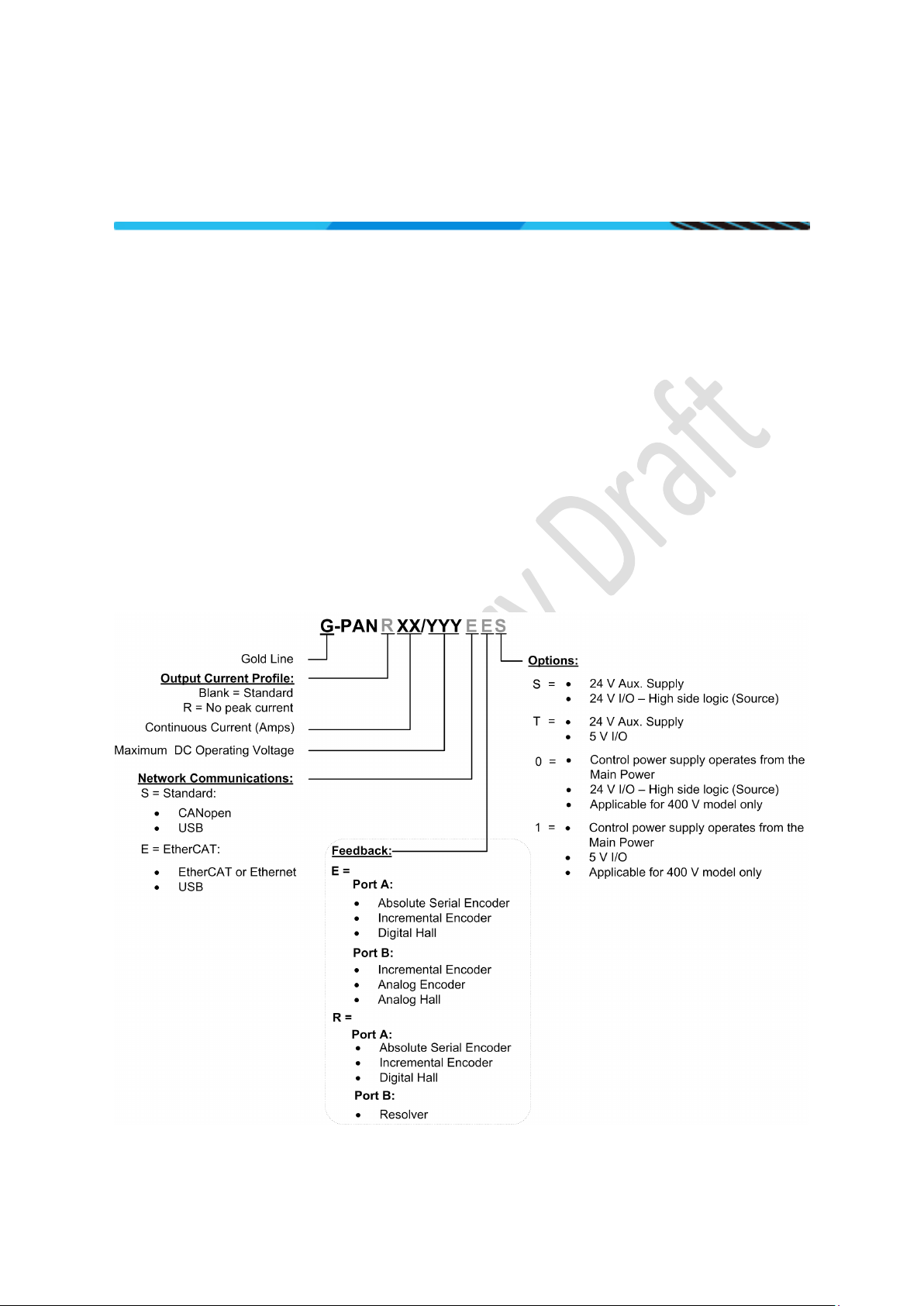
Table of Contents
Notice
This guide is delivered subject to the following conditions and restrictions:
• This guide contains proprietary information belonging to Elmo Motion Control Ltd. Such
information is supplied solely for the purpose of assisting users of the Gold Panther servo drive
in its installation.
• The text and graphics included in this manual are for the purpose of illustration and reference
only. The specifications on which they are based are subject to change without notice.
• Information in this document is subject to change without notice.
Document no. MAN-G-PANIG-EC (Ver. 1.000)
Copyright 2014
Elmo Motion Control Ltd.
All rights reserved.
Catalog Number
|Physical Specifications|www.elmomc.com
Page 3

Table of Contents
Revision History
Version Date Details
Ver. 1.000 February 2014 Initial release
|Physical Specifications|www.elmomc.com
Page 4

Table of Contents
Table of Contents
MAN-G-PANIG-EC (V er. 1.000)
Chapter 1: This Installation Guide ..................................................................................... 6
Chapter 2: Product Description ......................................................................................... 6
Chapter 3: Technical Information ...................................................................................... 7
3.1. Physical Specifications .................................................................................................... 7
3.2. Technical Data ................................................................................................................ 7
3.2.1. Auxiliary Supply ............................................................................................... 8
3.2.2. Product Features ............................................................................................. 8
Chapter 4: Installation ...................................................................................................... 9
4.1. Unpacking the Drive Components ................................................................................. 9
4.2. Connectors ................................................................................................................... 10
4.2.1. Connector Types ............................................................................................ 10
4.2.2. Pinouts ........................................................................................................... 11
4.2.2.1. Motor Power ................................................................................ 11
4.2.2.2. Main Power .................................................................................. 11
4.2.2.3. Auxiliary Power Connector (J3) .................................................... 12
4.2.2.4. Connector J2 ................................................................................. 13
4.2.2.5. Connector J1 ................................................................................. 16
4.3. Mounting the Gold Panther ......................................................................................... 18
4.4. Integrating the Gold Panther on a PCB ........................................................................ 19
4.5. Connection Diagrams ................................................................................................... 19
4
Chapter 5: Wiring ........................................................................................................... 24
5.1. Main Power, Motor Power and Auxiliary Power .......................................................... 26
5.1.1. Motor Power ................................................................................................. 26
5.1.2. Main Power ................................................................................................... 26
5.1.2.1. Direct-to-Mains Power Source (Non-Isolated Rectifier) ............... 27
5.1.2.2. Battery Power Supply ................................................................... 31
5.1.3. +24 V Auxiliary Supply (J3) ............................................................................. 31
5.2. STO (Safe Torque Off) Inputs (J1) ................................................................................. 33
5.3. Feedback ...................................................................................................................... 35
5.3.1. Port A (J2, J1) ................................................................................................. 35
5.3.1.1. Incremental Encoder Connection Diagram .................................. 37
5.3.1.2. Absolute Serial Encoder Connection Diagram .............................. 38
5.3.1.3. Hall Sensor Connection Diagram .................................................. 39
5.3.2. Port B (J2, J1) ................................................................................................. 40
5.3.2.1. Incremental Encoder Connection Diagram .................................. 41
5.3.2.2. Interpolated Analog Encoder Connection Diagram...................... 42
5.3.2.3. Resolver Connection Diagram ...................................................... 43
5.3.3. Port C – Emulated Encoder Output (J2)......................................................... 43
5.4. User I/Os .......................................................................................................................
45
|Physical Specifications|www.elmomc.com
Page 5

Table of Contents
Table of Contents
MAN-G-PANIG -EC (Ver. 1.000)
5.4.1. Digital Inputs (J1) ........................................................................................... 45
5.4.2. Digital Outputs (J1) ........................................................................................ 48
5.4.3. Input (J2) ........................................................................................................ 51
5.5. Communications ........................................................................................................... 52
5.5.1. CAN Communication (J2) ............................................................................... 52
5.5.2. USB 2.0 Communication (J2) ......................................................................... 54
5.5.3. EtherCAT Communication (J2) ....................................................................... 55
5.5.4. Ethernet Communication (J2) ........................................................................ 57
5.5.5. EtherCAT/Ethernet Line Interface ................................................................. 59
Chapter 6: Powering Up ................................................................................................. 60
6.1. Initializing the System .................................................................................................. 60
Chapter 7: Heat Dissipation ............................................................................................ 61
7.1. Gold Panther Thermal Data .......................................................................................... 61
7.2. Heat Dissipation Data ................................................................................................... 61
7.3. How to Use the Charts ................................................................................................. 62
5
Chapter 8: Dimensions ................................................................................................... 63
|Physical Specifications|www.elmomc.com
Page 6

Gold Panther Installation Guide
Table of Contents
Chapter 1: This Installation Guide
Chapter 2: Product Description
MAN-G-PANIG -EC (Ver. 1.000)
6
This installation Guide details the technical data, pinouts, and power connectivity of the Gold
Panther. For a comprehensive detailed description of the functions and connections of the drive,
refer to the MAN-G-Drive Hardware manual, and especially the sections in Chapter 7 which describe
PCB Mounted products.
The Gold Panther series of digital servo drives are highly resilient and designed to deliver the
highest density of power and intelligence. The Gold Panther delivers up to 10 kW of continuous
power or 16 kW of peak power in a compact package.
The digital drives are part of Elmo’s advanced Gold Line. They operate from a DC power source in
current, velocity, position and advanced position modes, in conjunction with a permanent-magnet
synchronous brushless motor, DC brush motor, linear motor or voice coil. They are designed for use
with any type of sinusoidal and trapezoidal commutation, with vector control. The Gold Panther can
operate as a stand-alone device or as part of a multi-axis system in a distributed configuration on a
real-time network.
The drives are easily set up and tuned using Elmo Application Studio software tools. This Windowsbased application enables users to quickly and simply configure the servo drive for optimal use with
their motor. The Gold Panther, as part of the Gold Line, is fully programmable with Elmo’s motion
control language.
Power to the drives is provided by a DC power source (not included with the Gold Panther).
Since the power stage is fully isolated from the control stage, the DC rectifier can be fed directly
from the mains, without the need for a bulky and expensive transformer.
If backup functionality is required to store control parameters in the event of a mains power
outage, then an S or T-model Gold Panther should be used, with an external 24 VDC isolated supply
connected to it.
Note: The backup functionality can operate from an isolated voltage source within the range of
18 to 30 VDC.
Whenever backup functionality is not required, Gold Panther models that have 0 or 1 suffix (only for
400V models) in the catalog number (see page 9) can be used, i.e., they do not have a 24 V control
supply. In these models, a smart control-supply algorithm enables the Gold Panther to operate with
only the main power supply VP+ and VN-, with no need for a 24 VDC auxiliary power supply for the
logic.
The Gold Panther is a PCB-mounted device which enables efficient and cost-effective
implementation. However, stand-alone integrated products (the Gold DC Trombone and Gold Solo
Trombone) are also available, using pluggable connections.
|Physical Specifications|www.elmomc.com
Page 7

Gold Panther Installation Guide
Table of Contents
Chapter 3: Technical Information
MAN-G-PANIG -EC (Ver. 1.000)
7
3.1. Physical Specifications
Feature Units All Types
Weight g (oz) 300 g (10.6 oz)
Dimension mm (in) 111 x 76 x 34 (4.37" x 3" x 1.34")
Mounting method PCB Mounted
3.2. Technical Data
Feature Units 12/400 16/400 R17/400 R22/400 8/800 12/800 R11/800 R16/800
Minimum supply
voltage
Nominal supply voltage VDC 325 560 for 400 VAC
Maximum supply
voltage
Maximum continuous
power output
Efficiency at rated
power (at nominal
conditions)
Auxiliary supply
voltage option
Auxiliary power supply VA ≤5 VA without external loading
Continuous current
limit (Ic) Amplitude
sinusoidal/DC
trapezoidal
commutation
VDC
VDC 400 780
W Up to 10 kW of continuous qualitative power
% > 98
VDC 18 to 30 VDC (only in S or T type)
A 12 16 17 22 8 12 11 16
*For S or T type = 50
For 0 or 1 suffix type = 100
≤8 VA with full external loading
*For S or T type = 95
680 for 480 VAC
Sinusoidal continuous
RMS current limit (Ic)
Peak current limit A 2 x Ic No peak 2 x Ic No peak
A 8.5 11.3 12 15.5 5.7 8.5 7.8 11.3
*See page 9 for details on the part number. The S or T suffix appears in models where there is a 24 V
control supply. If there is an 0 or 1 suffix, the control power supply operates from the main power.
|Physical Specifications|www.elmomc.com
Page 8

Gold Panther Installation Guide
Table of Contents
MAN-G-PANIG -EC (Ver. 1.000)
Note on current ratings: The current ratings of the Gold Panther are given in units of DC
amperes (ratings that are used for trapezoidal commutation or DC motors). The RMS (sinusoidal
commutation) value is the DC value divided by 1.41.
3.2.1. Auxiliary Supply
Feature Details
Auxiliary power supply Isolated DC source only
Auxiliary supply input voltage 18 VDC to 30 VDC
Auxiliary supply input power < 4 VA (this includes the 5 V/200 mA load for the main
encoder only)
< 5.5 VA (this includes the 5 V/400 mA load on the main
encoder and feedback B)
3.2.2. Product Features
8
Main Feature Details Presence and No.
STO
TTL √
PLC Source √
Digital Input Option
TTL 6
PLC Source 6
Digital Output Option
TTL 4
PLC Source 4
Analog Input
Feedback
Communication Option
Differential ±10V/Single Ended 1/1
Standard Port A, B, & C √
USB √
EtherCAT √
CAN √
RS-232 TTL level √
|Technical Data|www.elmomc.com
Page 9

Gold Panther Installation Guide
Table of Contents
Chapter 4: Installation
MAN-G-PANIG -EC (Ver. 1.000)
The Gold Panther must be installed in a suitable environment and properly connected to its voltage
supplies and the motor.
4.1. Unpacking the Drive Components
Before you begin working with the Gold Panther, verify that you have all of its components, as
follows:
• The Gold Panther servo drive
• The Elmo Application Studio (EAS) software and software manual
The Gold Panther is shipped in a cardboard box with Styrofoam protection.
To unpack the Gold Panther:
1. Carefully remove the servo drive from the box and the Styrofoam.
2. Check the drive to ensure that there is no visible damage to the instrument. If any damage
has occurred, report it immediately to the carrier that delivered your drive.
3. To ensure that the Gold Panther you have unpacked is the appropriate type for your
requirements, locate the part number sticker on the side of the Gold Panther. It looks like
this:
9
4. Verify that the Gold Panther type is the one that you ordered, and ensure that the voltage
meets your specific requirements.
The part number at the top provides the type designation. Refer to the appropriate part
number in the section Catalog Number at the beginning of the installation guide.
|Unpacking the Drive Components|www.elmomc.com
Page 10
Gold Panther Installation Guide
Table of Contents
MAN-G-PANIG -EC (Ver. 1.000)
4.2. Connectors
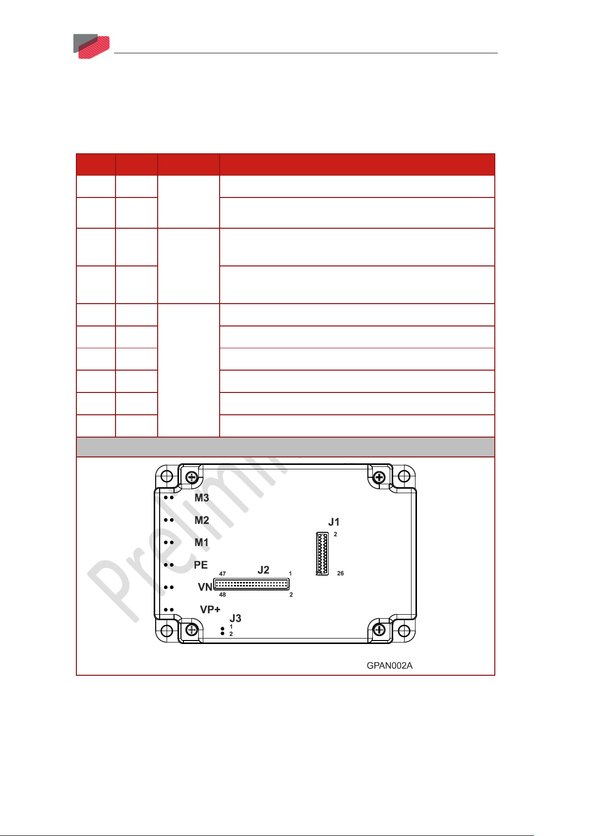
The Gold Panther has 9 connectors.
4.2.1. Connector Types
Port Pins Type Function
10
J1 2x13 1.27 mm
J2 2x24 Communications
pitch 0.41
Analog Input, Feedback
mm sq
J3/1 1 2 mm pitch
0.51 mm sq
24 VDC Auxiliary power input positive (Only in Trombones
with the S or T suffix)
J3/2 1 24 VDC Auxiliary supply input return (Only in Trombones
with the S or T suffix)
VP+ 2 2.54 mm
VN- 2 Negative DC power input
pitch
Positive DC power input
0.64 mm sq
PE 2 Protective earth
M1 2 Motor power output 1
M2 2 Motor power output 2
M3 2 Motor power output 3
Connector Location
Table 1: Connector Types
|Connectors|www.elmomc.com
Page 11

Gold Panther Installation Guide
Table of Contents
MAN-G-PANIG -EC (Ver. 1.000)
11
4.2.2. Pinouts
The pinouts in this section describe the function of each pin in the Gold Panther connectors that are
listed in Table 1.
4.2.2.1. Motor Power
For full details see Section 7.3 in the manual: MAN-G-Drive Hardware.
Pin Function Cable Pin Positions
Brushless
Motor
Brushed DC
Motor
M3 Motor phase Motor Motor
M2 Motor phase Motor Motor
M1 Motor phase Motor N/C
PE Protective
Power and Motor
Earth
Connector Type: 2.54 mm pitch 0.64 mm sq
Table 2: Connector for Motor
4.2.2.2. Main Power
For full details about connecting main power see Section 5.1.2.
Pin Function Cable Pin Positions
PE Protective Earth Power and Motor
VN- DC Negative Power
Power
input
VP+ DC Positive Power
Power
input
Connector Type: 2.54 mm pitch 0.64 mm sq
Table 3: Connector for Main Power
|Connectors|www.elmomc.com
Page 12
Gold Panther Installation Guide
Table of Contents
MAN-G-PANIG -EC (Ver. 1.000)
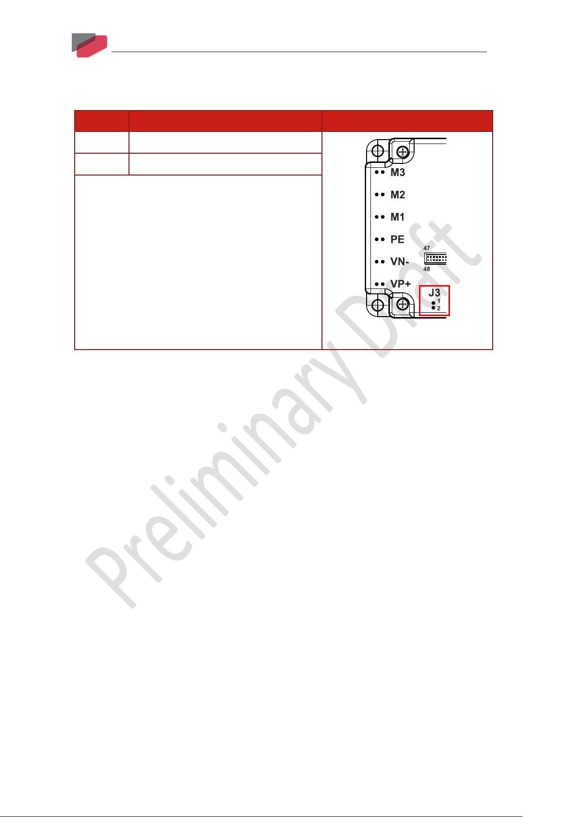
4.2.2.3. Auxiliary Power Connector (J3)
For full details about connecting auxiliary power, see Section 5.1.3.
Pin (J3) Function Pin Positions
1 +24 V Auxiliary Supply Input Positive
2 24 V RET Auxiliary Supply Input Return
Connector Type: 2 mm pitch 0.51 mm sq
12
Table 4: Auxiliary 24 VDC Backup Supply Pins and Polarity
|Connectors|www.elmomc.com
Page 13

Gold Panther Installation Guide
Table of Contents
Feedback, Analog input,
MAN-G-PANIG -EC (Ver. 1.000)
4.2.2.4. Connector J2
communications– see Section 7.5 in
the manual: MAN-G-Drive
Hardware.
Connector Type: 1.27 mm pitch
0.41 mm sq
For full details about connecting
feedback port A see Section 7.6.1 in
the MAN-G-Drive Hardware manual
for full details.
For full details about connecting
feedback port B see Section 7.6.2 in
the MAN-G-Drive Hardware manual
for full details.
13
Note regarding the EtherCAT and CAN communication options:
The J2 Connector exports all supported communication links. However, note that CAN and
EtherCAT are not available in the same version of the Gold Panther and are thus not operational
simultaneously. See the part number diagram in Section 4.1 above for the different Gold Panther
configurations.
For full details about connecting
feedback port C see Section 7.6.3 in
the MAN-G-Drive Hardware
manual.
Analog Inputs – see Section 7.7.3 in
the manual: MAN-G-Drive
Hardware.
For full details about connecting
communication see Section 7.8 in
the manual: MAN-G-Drive
Hardware.
|Connectors|www.elmomc.com
Page 14

Gold Panther Installation Guide
Table of Contents
1
PortA_ENC_A+ /ABS_CLK+
Port A- channel A/ Absolute encoder clock+
2
PortC_ENCO_A-
Port C- channel A complement output
encoder clock-
4
PortC_ENCO_A+
Port C- channel A output
5
PortA_ENC_B+/ABS_DATA+
Port A - channel B/ Absolute encoder Data+
6
PortC_ENCO_B-
Port C - channel B complement output
encoder Data-
8
PortC_ENCO_B+
Port C - channel B output
9
PortA_ENC_INDEX+
Port A – index
10
PortC_ENCO_INDEX-
Port C - index complement output
11
PortA_ENC_INDEX-
Port A - index complement
12
PortC_ENCO_INDEX+
Port C - index output
13
PortB_ENC_A+/SIN+
Port B - channel A
14
HC
Hall sensor C input
15
PortB_ENC_A-/SIN-
Port B - channel A complement
16
HB
Hall sensor B input
17
PortB_ENC_B+/COS+
Port B - channel B
18
HA
Hall sensor A input
19
PortB_ENC_B-/COS-
Port B - channel B complement
20
ANLRET
Analog return
PortB_ENC_INDEX+/ANALOG_I+
Port B – index+/ Analog_Index+
f= 1/TS, 50 mA Maximum
22
ANALOG1+
Analog input 2
PortB_ENC_INDEX-/ANALOG_I-
Port B – index -/ Analog _Index-
f= 1/TS, 50 mA Maximum
24
ANALOG1-
Analog input 1 complement
25
COMRET
Common return
26
+3.3V
3.3 V supply voltage for EtherCAT LEDs
27
PHY_IN_RX+
EtherCAT In receive
28
EtherCAT: PHY_OUT_RX+
EtherCAT Out receive
29
PHY_IN_RX-
EtherCAT In receive complement
MAN-G-PANIG -EC (Ver. 1.000)
Pin (J2) Signal Function
3 PortA_ENC_A-/ABS_CLK- Port A- channel A complement / Absolute
7 PortA_ENC_B-/ABS_DATA- Port A - channel B complement / Absolute
14
21
RESOLVER_OUT+ Vref complement
23
RESOLVER_OUT- Vref complement
|Connectors|www.elmomc.com
Page 15

Gold Panther Installation Guide
Table of Contents
30
EtherCAT: PHY_OUT_RX-
EtherCAT Out receive complement
32
COMRET
Common return
33
PHY_IN_TX+
EtherCAT In transmit
34
EtherCAT: PHY_OUT_TX+
EtherCAT Out transmit complement
35
PHY_IN_TX-
EtherCAT In transmit complement
36
EtherCAT: PHY_OUT_TX-
EtherCAT Out transmit complement
37
PHY_IN_LINK_ACT
EtherCAT In active LED
EtherCAT: PHY_OUT_LINK_ACT
EtherCAT Out active LED
CAN: CAN_L
CAN_L bus line (dominant low)
39
PHY_IN_SPEED
EtherCAT In speed LED
EtherCAT: PHY_OUT_SPEED
EtherCAT Out speed LED
CAN: CAN_H
CAN_H bus line (dominant high)
41
USBD-
USB data complement
42
USBD+
USB data
43
COMRET
Common return
44
USB_VBUS
USB VBUS 5V
I/O (refer to G-Drive Hardware manual)
46
COMRET
Common return
47
N/A
N/A – Not in use, keep unconnected
(refer to G-Drive Hardware manual)
MAN-G-PANIG -EC (Ver. 1.000)
Pin (J2) Signal Function
31 COMRET Common return
38
40
15
45 RS232_RX /SB_OUT There are two options for this pin:
Option 1: RS232 receive (default)
Option 2: Serial Bus output for extended
48 RS232_TX /SB_IN There are two options for this pin:
Option 1: RS232 transmit (Default)
Option 2: Serial Bus IN for extended I/O
Table 5: Connector J2 – Feedback and Analog Input
|Connectors|www.elmomc.com
Page 16

Gold Panther Installation Guide
Table of Contents
Digital Inputs, Digital Outputs, STO,
MAN-G-PANIG -EC (Ver. 1.000)
4.2.2.5. Connector J1
16
Amplifier and Communication LEDs, Encoder
Supply
Connector Type: 1.27 mm pitch 0.41 mm sq
For full details about connecting digital input
see Section 7.7.1 in the MAN-G-Drive
Hardware manual
For full details about connecting digital
output see Section 7.7.2 in the MAN-G-Drive
Hardware manual.
Pin (J1) Signal Function
1 COMRET Common Return
2 +5VE Encoder +5V supply
3 SB_Load Serial Bus Load for extended IO (refer to G-Drive
4 SB_Clock Serial Bus_Clock (9.375Mhz) for extended IO (refer to
5
6
7
8
9
10
INRET1_6 Programmable digital inputs 1–6 return
IN1 Programmable digital input 1
IN2 Programmable digital input 2
IN3 Programmable digital input 3
IN4 Programmable digital input 4
IN5 Programmable digital input 5
Hardware manual)
G-Drive Hardware manual)
11
12
13
14
IN6 Programmable digital input 6
STO_RET Safety signal return
STO2 Safety 2 input (default 24 V)
STO1 Safety 1 input (default 24 V)
15 LED_ETHERCAT ERR LED Status EtherCAT ERR (Cathode)
16 LED_ETHERCAT RUN LED Status EtherCAT RUN (Cathode)
|Connectors|www.elmomc.com
Page 17

Gold Panther Installation Guide
Table of Contents
MAN-G-PANIG -EC (Ver. 1.000)
Pin (J1) Signal Function
17
17
18
19
LED2 Bi-color indication output 2 (Cathode)
LED1 Bi-color indication output 1 (Cathode)
COMRET Common return
20 ANALOG_IN2 Analog input 2
21
22
23
24
OUT2 Programmable output 2
OUT1 Programmable output 1
OUT4 Programmable output 4
OUT3 Programmable output 3
25 VDDRET VDD Supply Return
26 VDD VDD Supply (5V up to 30V)
Table 6: Connector J1 – Communication
|Connectors|www.elmomc.com
Page 18
Gold Panther Installation Guide
Table of Contents
MAN-G-PANIG -EC (Ver. 1.000)
18
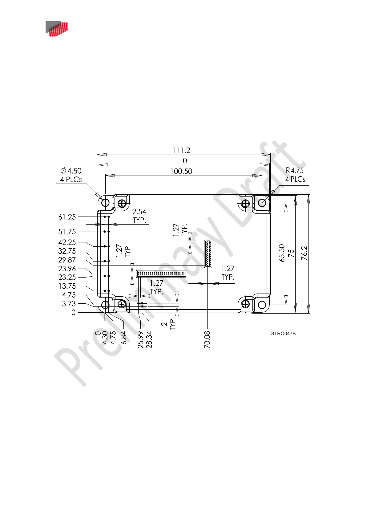
4.3. Mounting the Gold Panther
The Gold Panther is designed for mounting on a printed circuit board (PCB). It is connected by
1.27 mm pitch 0.41 mm square pins and 2.54 mm pitch 0.64 mm square pins. When integrating the
Gold Panther into a PCB, be sure to leave about 1 cm (0.4") outward from the heat-sink to enable
free convection of the air around the Gold Panther. We recommend that the Gold Panther be
soldered directly to the board. Alternatively, though this is not recommended, the Gold Panther can
be attached to socket connectors mounted on the PCB. However, if the PCB is enclosed in a metal
chassis, we recommend that the Gold Panther be screw-mounted to it as well to help with heat
dissipation. The Gold Panther has screw-mount holes on each corner of the heat-sink for this
purpose.
Figure 1: Gold Panther Footprint
|Mounting the Gold Panther|www.elmomc.com
Page 19

Gold Panther Installation Guide
Table of Contents
MAN-G-PANIG -EC (Ver. 1.000)
19
4.4. Integrating the Gold Panther on a PCB
The Gold Panther is designed to be mounted on a PCB, either by soldering its pins directly to the
PCB. Refer to the Gold Line Trombone Design Guide MAN-G-TROIDG for further information.
4.5. Connection Diagrams
There are two connection diagrams for EtherCAT and two for CAN that show the two different ways
of connecting the power supply:
• 400 V and 800 V S or T -models (the catalog number has an S or T suffix) that feature backup
functionality and require an auxiliary 24 V backup supply. The drive will not be operative
without the external 24 VDC supply.
• 400 V model without backup functionality (0 or 1 suffix). The drive’s internal DC/DC converter is
fed from the VP+ and VN- of the internal drive’s bus line.
|Integrating the Gold Panther on a PCB|www.elmomc.com
Page 20
Gold Panther Installation Guide
Table of Contents
MAN-G-PANIG -EC (Ver. 1.000)
20
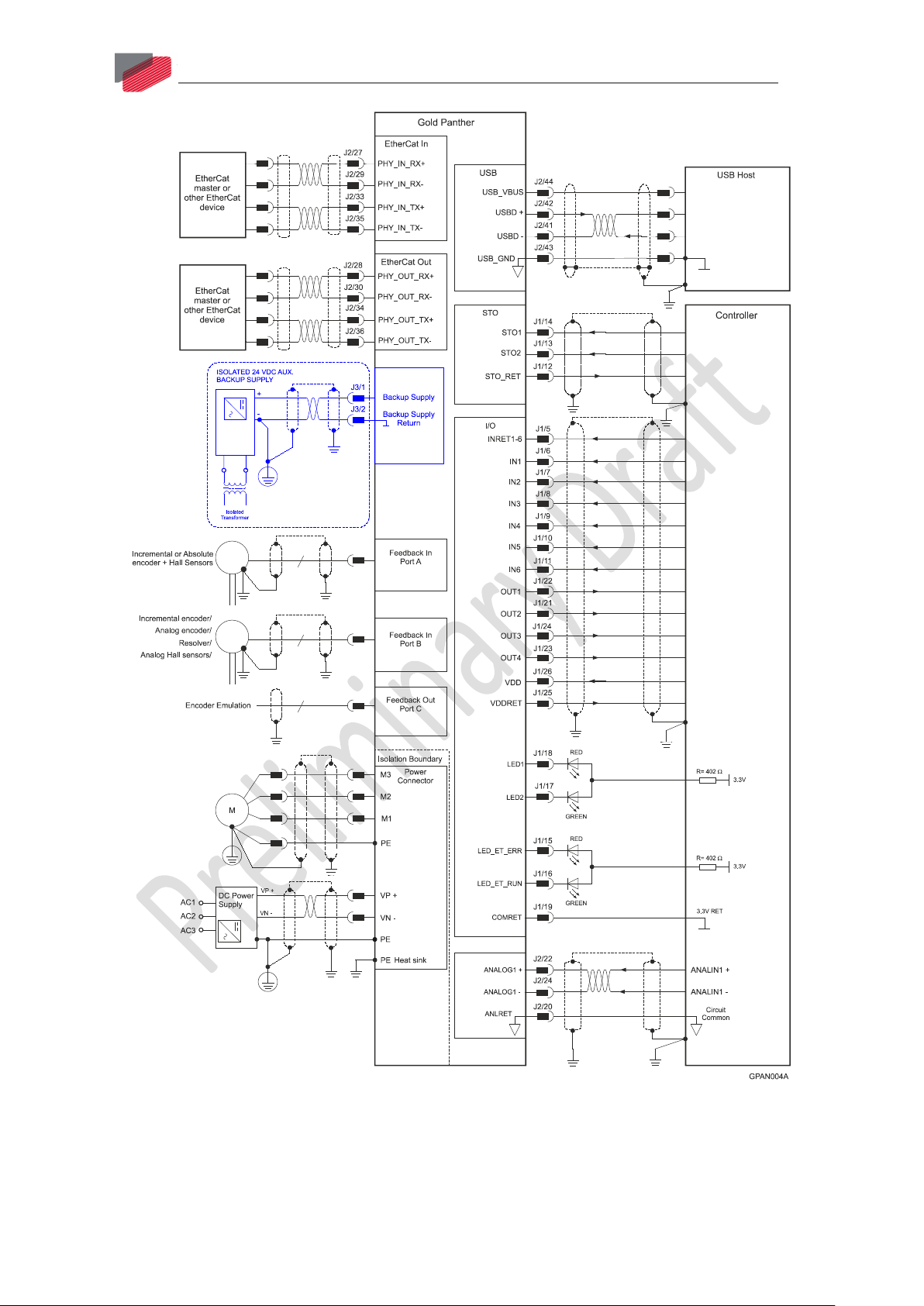
Figure 2: Gold Panther Connection Diagram for EtherCAT – with Backup Functionality
(S or T Model Drive)
|Connection Diagrams|www.elmomc.com
Page 21

Gold Panther Installation Guide
Table of Contents
MAN-G-PANIG -EC (Ver. 1.000)
21
Figure 3: Gold Panther Connection Diagram for EtherCAT – 400 V without Backup Functions
(0 or 1 Suffix)
|Connection Diagrams|www.elmomc.com
Page 22
Gold Panther Installation Guide
Table of Contents
MAN-G-PANIG -EC (Ver. 1.000)
22
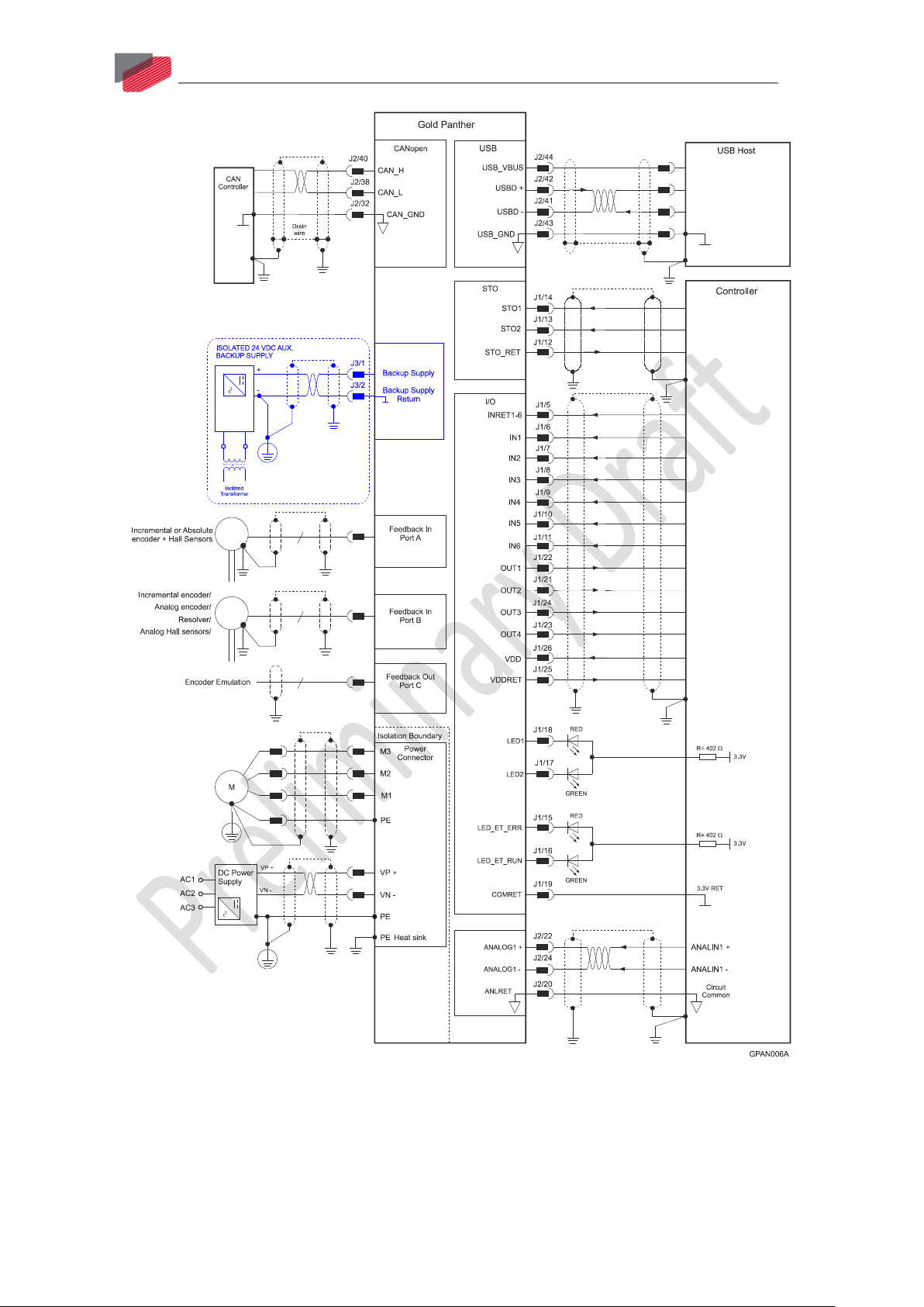
Figure 4: Gold Panther Connection Diagram for CAN – with Backup Functionality
(S or T Model Drive)
|Connection Diagrams|www.elmomc.com
Page 23

Gold Panther Installation Guide
Table of Contents
MAN-G-PANIG -EC (Ver. 1.000)
23
Figure 5: Gold Panther Connection Diagram for CAN – 400 V without Backup Functions
(0 or 1 Suffix)
|Connection Diagrams|www.elmomc.com
Page 24
Gold Panther Installation Guide
Table of Contents
Chapter 5:
Wiring
MAN-G-PANIG -EC (Ver. 1.000)
24
Once the product is mounted, you are ready to wire the device. Proper wiring, grounding and
shielding are essential for ensuring safe, immune and optimal servo performance of the drive.
The following table legend describes the wiring symbols detailed in all installation guides.
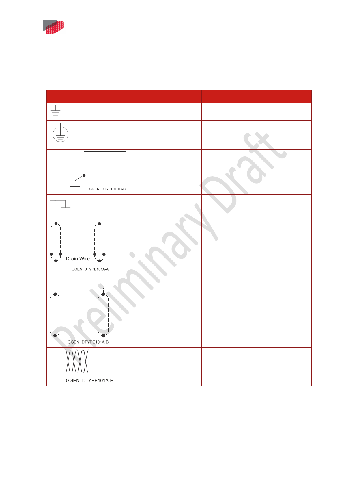
Wiring Symbol Description
Earth connection (PE)
Motor Protection Earth Connection
Metal chassis connection
Common at the Controller
Shielded cable with drain wire.
The drain wire is a non-insulated wire
that is in direct contact with the braid
(shielding).
Shielded cable with drain wire
significantly simplifies the wiring and
earthing.
Shielded cable braid only, without drain
wire.
Twisted-pair wires
|Connection Diagrams|www.elmomc.com
Page 25

Gold Panther Installation Guide
Table of Contents
MAN-G-PANIG -EC (Ver. 1.000)
Wiring Symbol Description
Encoder Earthing.
The drawing displays two earth
connections. Only one of the Earth
connections described below is mandatory.
Earthing Type 1 is for encoders where the
earth connection consists of the braid of
the shielded cable being connected to Earth
via the earthed chassis earthing.
Earthing Type 2 is for encoders where the
earth connection consists of earthing the
Drain Wire to a device with a terminal
internally connected to earth (PE) in the
connector.
25
Earthing the Encoder and connecting the
Earth (PE) to the drive COMRET is
mandatory to insure reliable operation,
high noise immunity and rejection of
voltage common mode interferences.
|Connection Diagrams|www.elmomc.com
Page 26

Gold Panther Installation Guide
Table of Contents
MAN-G-PANIG -EC (Ver. 1.000)
26
5.1. Main Power, Motor Power and Auxiliary Power
The Gold Panther receives power from main and auxiliary supplies and delivers power to the motor.
Note: There are multiple voltage ratings of the Gold Panther (80 V to 780 V), so you must use the
correct power supply according to the maximum operating voltage of the Gold Panther. See Section
Chapter 3: Technical Information
5.1.1. Motor Power
Pin Function Cable Pin Positions
Brushless Motor Brushed DC Motor
M3 Motor phase Motor Motor
M2 Motor phase Motor Motor
M1 Motor phase Motor N/C
PE Protective
Power and Motor
Earth
Table 7: Connector for Motor
5.1.2. Main Power
Pin Function Cable Pin Positions
PE Protective Earth Power and Motor
VN- DC Negative Power input Power
VP+ DC Positive Power input Power
Table 8: Connector for Main Power
|Main Power, Motor Power and Auxiliary Power|www.elmomc.com
Page 27

Gold Panther Installation Guide
Table of Contents
MAN-G-PANIG -EC (Ver. 1.000)
27
The DC power for the Gold Panther is delivered from a separated rectifying unit (supplied by the
user). Elmo recommends using the Tambourine rectifier specifically designed for use with Elmo
drives which offers a range of versatile options.
The following sections contain topology recommendations for implementing three-phase and
single-phase supply chains.
The power stage of the Gold Panther is fully isolated from the other sections of the Gold Panther,
such as the control-stage and the heat-sink. This isolation allows the user to connect the common of
the control section to the PE, a connection which significantly contributes to proper functionality,
safety and EMI immunity, leading to better performance of the Gold Panther.
In addition, this isolation simplifies the requirements of the DC power supply that is used to power
the DC bus of the Gold Panther, by allowing it to operate with a non-isolated DC power source (a
direct-to-mains connection) which eliminates the need for a bulky and expensive isolation
transformer.
However, as well as operating from a non-isolated/direct-to-mains DC power supply, the Gold
Panther can also operate from an isolated power supply or batteries.
When rectifying an AC voltage source, the AC voltage level must be limited to 270 VAC so as not to
exceed the maximum 390 VDC in the case of a 400 VDC drive, or 528 VAC so as not to exceed the
maximum 747 VDC in the case of an 800 VDC drive.
5.1.2.1. Direct-to-Mains Power Source (Non-Isolated Rectifier)
This section relates to the configuration of the power supply and drive, which are connected
directly to the mains.
To connect the non-isolated DC power supply:
1. For best immunity, it is highly recommended to use twisted cables for the DC power supply
cable. A 3-wire shielded cable should be used. The gauge is determined by the actual current
consumption of the motor.
2. Connect both ends of the cable shield to the closest PE connections.
3. Tie one end to the power supply’s PE terminal, and tie the other end either to the PE pins of the
module/PE terminal of the integration board, or attach it to one of the four mounting screws of
the drive’s heat-sink.
|Main Power, Motor Power and Auxiliary Power|www.elmomc.com
Page 28

Gold Panther Installation Guide
Table of Contents
MAN-G-PANIG -EC (Ver. 1.000)
5.1.2.1.a Three-Phase Direct-to-Mains Connection Topology
Figure 6: Non-Isolated Three-Phase Connection Topology
28
Caution:
• Do not connect VN- to PE. In a direct-to-mains connection the VN- must not be
connected to the PE, as this will cause irreparable damage to the system.
• Take care and note that in a direct-to-mains connection the Neutral point is not
the most negative voltage level. It is the mid-point level of the rectified DC bus.
|Main Power, Motor Power and Auxiliary Power|www.elmomc.com
Page 29

Gold Panther Installation Guide
Table of Contents
MAN-G-PANIG -EC (Ver. 1.000)
5.1.2.1.b Single-Phase Direct-to-Mains Connection Topology
Figure 7: Non-Isolated Single-Phase Connection Topology
29
The Power Supply is connected directly to the mains AC line.
Warning:
• Do not connect VN- to PE. In a direct-to-mains connection the VN- must not be
connected to the PE, as this will cause irreparable damage to the system.
• Take care and note that in a direct-to-mains connection the Neutral point is not
the most negative voltage level. It is the mid-point level of the rectified DC bus.
|Main Power, Motor Power and Auxiliary Power|www.elmomc.com
Page 30
Gold Panther Installation Guide
Table of Contents
MAN-G-PANIG -EC (Ver. 1.000)
5.1.2.1.c Multiple Connections Topology
In a multi-axis application it is likely that a single power supply can feed several drives in parallel.
This topology is efficient and cost saving, by reducing the number of power supplies and the
amount of wiring. Most importantly it utilizes an energy sharing environment among all the drives
that share the same DC bus network.
The power supply is connected directly to the mains AC line, and it feeds more than one drive.
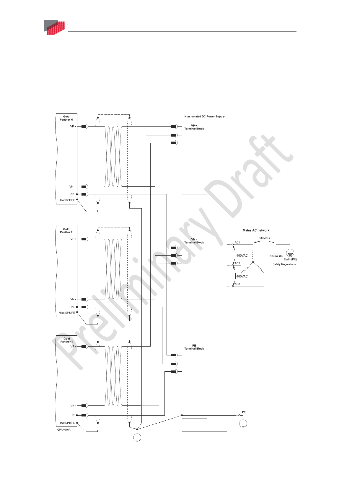
30
Figure 8: Non-Isolated Three-Phase Multiple Connection Topology
|Main Power, Motor Power and Auxiliary Power|www.elmomc.com
Page 31

Gold Panther Installation Guide
Table of Contents
MAN-G-PANIG -EC (Ver. 1.000)
5.1.2.2. Battery Power Supply
Figure 9: Battery Connection Topology
31
Caution: When using batteries, it is recommended to connect the negative pole
to the PE.
When doing so, the charger of the battery
must be isolated from the mains by
an isolation transformer.
5.1.3. +24 V Auxiliary Supply (J3)
Pin (J3) Function Pin Positions
1 +24 V Auxiliary Supply Input Positive
2 24 V RET Auxiliary Supply Input Return
Table 9: Auxiliary 24 VDC Backup Supply Pins and Polarity
|Main Power, Motor Power and Auxiliary Power|www.elmomc.com
Page 32

Gold Panther Installation Guide
Table of Contents
MAN-G-PANIG -EC (Ver. 1.000)
32
In drives that have an 0 or 1 suffix (only for 400V models), a smart control-supply algorithm enables
the Gold Panther to operate with the main power supply only, with no need for an auxiliary supply
voltage to supply the drive’s logic section. However, it should be noted that in such model there is
no backup ability at all.
If backup functionality is required to store control parameters in the event of a mains power
outage, then an S or T-model Gold Panther should be used, with an external 24 VDC isolated supply
connected to it.
Note that the S or T-model Gold Panther always requires an external 24 VDC power supply,
regardless of whether or not backup functionality is required.
Connect the auxiliary 24 VDC power supply as described below.
To connect the 24 VDC backup supply:
1. Use a 24 AWG twisted pair shielded cable. The shield should have copper braid.
2. The source of the 24 VDC backup supply must be isolated with an isolation transformer.
3. For safety and EMI reasons, connect the return of the 24 VDC backup supply to the closest
ground (PE).
4. Connect the cable shield to the closest ground (PE) near the power source.
5. Before applying power, first verify that the polarity of the connection is correct.
Figure 10: Auxiliary 24 VDC Backup Supply Connection Diagram
|Main Power, Motor Power and Auxiliary Power|www.elmomc.com
Page 33

Gold Panther Installation Guide
Table of Contents
MAN-G-PANIG -EC (Ver. 1.000)
33
5.2. STO (Safe Torque Off) Inputs (J1)
Activation of Safe Torque Off causes the drive to stop providing power that can cause rotation (or
motion in the case of a linear motor) to the motor.
This function may be used to prevent unexpected motor rotation (of brushless DC motors) without
disconnecting the drive from the power supply.
The motor is active only as long as 24 VDC (or 5 V for the TTL option) is provided to both STO1 and
STO2. Whenever any input voltage is no longer present, power is not provided to the motor and the
motor shaft continues to rotate to an uncontrolled stop.
In circumstances where external influences (for example, falling of suspended loads) are present,
additional measures such as mechanical brakes are necessary to prevent any hazard.
This function corresponds to an uncontrolled stop in accordance with Stop Category 0 of IEC 60204-
1.
Note: This function does not protect against electrical shock, and additional measures to turn
the power off are necessary.
The following table defines the behavior of the motor as a function of the state of the STO inputs:
Signal – STO1 Signal – STO2 Function
Not Active Not Active Motor is disabled
Not Active Active Motor is disabled
Active Not Active Motor is disabled
Active Active Motor can be enabled
Table 10: Motor Behavior According to Safety Inputs
Note: In the Gold Panther, STO1 also latches a software disable condition.
Pin (J1) Signal Function
14 STO1 Safety 1 input (default 24 V)
13 STO2 Safety 2 input (default 24 V)
12 STO_RET Safety signal return
Table 11: Safety Inputs Pin Assignments
See Figure 11 for the PLC option connection and Figure 12 for the TTL option connection.
|STO (Safe Torque Off) Inputs (J1)|www.elmomc.com
Page 34

Gold Panther Installation Guide
Table of Contents
MAN-G-PANIG -EC (Ver. 1.000)
34
Figure 11: STO Input Connection – PLC Option for S or 0 Suffixes
Figure 12: Safety Input Connection – TTL Option for T or 1 Suffixes
|STO (Safe Torque Off) Inputs (J1)|www.elmomc.com
Page 35

Gold Panther Installation Guide
Table of Contents
Port A
Port B
Port C
MAN-G-PANIG -EC (Ver. 1.000)
35
5.3. Feedback
Figure 13: Feedback Ports on J2
The Gold Panther has two configurable motion sensor input ports, namely, Port A and Port B, and
the emulated buffered output Port C. Motion sensors from the motor being controlled and from
other sources can be connected to any of the available inputs on Port A or Port B. Software
configuration designates each input a role, e.g., the incremental encoder on Port B is the controlled
motor position feedback, the Hall sensors on Port A are commutation feedback, and the
incremental encoder on Port A is follower input.
For more information about sensors and their use refer to the Gold Line Software Manual.
5.3.1. Port A (J2, J1)
Port A supports the following sensor inputs:
• Digital Hall sensors
• Incremental encoder or absolute serial encoder, depending on the specific model
Differential PWM signal input can be connected to Port A in the models that support input from an
incremental encoder. The PWM signal can be connected to the applicable pair of matching + and encoder channels and is configurable by software.
Differential pulse and direction signal inputs can be connected to Port A in the models that support
input from an incremental encoder. The signals can be connected to the applicable pair of matching
+ and - encoder channels and are configurable by software.
|Feedback|www.elmomc.com
Page 36

Gold Panther Installation Guide
Table of Contents
MAN-G-PANIG -EC (Ver. 1.000)
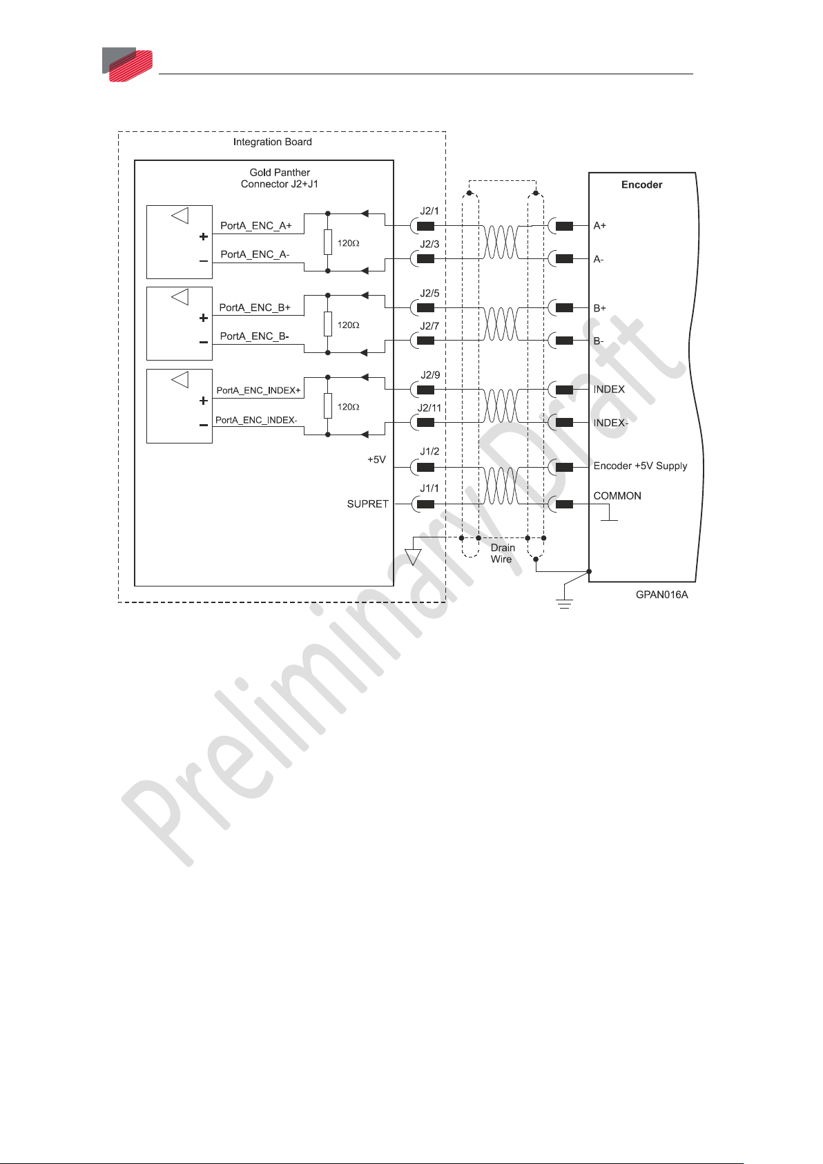
Port A - Incremental Encoder Port A - Absolute Serial Encoder
Pin Signal Function Signal Function
36
J1/2 +5V Encoder +5V
+5V Encoder +5V supply
supply
J1/1 SUPRET Supply return SUPRET Supply return
J2/1 PortA_ENC_A+ Channel A+ ABS_CLK+ Abs encoder clock +
J2/3 PortA_ENC_A- Channel A- ABS_CLK- Abs encoder clock -
J2/5 PortA_ENC_B+ Channel B+ ABS_DATA+ Abs encoder data +
J2/7 PortA_ENC_B- Channel B- ABS_DATA- Abs encoder data -
J2/9 PortA_ENC_Index+ Index+ Reserved Reserved
J2/11 PortA_ENC_Index- Index- Reserved Reserved
J2/18 HA Hall sensor A HA Hall sensor A
J2/16 HB Hall sensor B HB Hall sensor B
J2/14 HC Hall sensor C HC Hall sensor C
Table 12: Port A Pin Assignments
|Feedback|www.elmomc.com
Page 37
Gold Panther Installation Guide
Table of Contents
MAN-G-PANIG -EC (Ver. 1.000)
5.3.1.1. Incremental Encoder Connection Diagram
37
Figure 14: Port A Incremental Encoder Input – Recommended Connection Diagram
|Feedback|www.elmomc.com
Page 38

Gold Panther Installation Guide
Table of Contents
MAN-G-PANIG -EC (Ver. 1.000)
5.3.1.2. Absolute Serial Encoder Connection Diagram
38
Figure 15: Absolute Serial Encoder – Recommended Connection Diagram for Sensors Supporting
Data/Clock (e.g., Biss/SSI/EnDAT/etc.)
|Feedback|www.elmomc.com
Page 39

Gold Panther Installation Guide
Table of Contents
MAN-G-PANIG -EC (Ver. 1.000)
39
Figure 16: Absolute Serial Encoder – Recommended Connection Diagram for Sensors Supporting
Data Line Only (NRZ types, e.g., Panasonic / Mitutoyo / etc.)
5.3.1.3. Hall Sensor Connection Diagram
Figure 17: Hall Sensors Connection Diagram
|Feedback|www.elmomc.com
Page 40

Gold Panther Installation Guide
Table of Contents
MAN-G-PANIG -EC (Ver. 1.000)
40
5.3.2. Port B (J2, J1)
Port B supports the following sensors:
• Incremental encoder, interpolated analog encoder or as analog Hall sensors
Or:
• Resolver (separate hardware option)
Differential PWM signal input can be connected to port B in the models that support input from an
incremental encoder. The PWM signal can be connected to the applicable pair of matching + and –
encoder channels and is configurable by software.
Differential pulse and direction signal inputs can be connected to port B in the models that support
input from an incremental encoder. The signals can be connected to the applicable pair of matching
+ and – encoder channels and are configurable by software.
Port B - Incremental or
Port B - Resolver
Interpolated Analog Encoder
G-PANXXX/YYYYEXS G-PANXXX/YYYYRXS
Pin Signal Function Signal Function
J1/2 +5V Encoder +5V supply NC
J1/1 SUPRET Supply return SUPRET Supply return
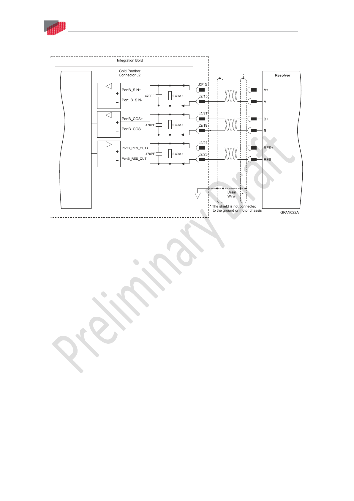
J2/13 PortB_ENC_A+/SIN+ Channel A+ / Sine+ SIN+ Sine+
J2/15 PortB_ENC_A-/SIN- Channel A- / Sine- SIN- Sine-
J2/17 PortB_ENC_B+/COS+ Channel B+ / Cosine+ COS+ Cosine+
J2/19 PortB_ENC_B-/ COS- Channel B - / Cosine - COS- Cosine-
J2/21 PortB_ENC_INDEX+/
Analog_Index+
J2/23 PortB_ENC_INDEX-/
Analog_Index-
Index +/
Analog_Index+
Index -/
Analog_Index-
RESOLVER_OUT+ Vref f=1/TS,
50 mA max.
RESOLVER_OUT- Vref
complement
f= 1/TS, 50 mA
max.
Table 13: Port B Pin Assignments
|Feedback|www.elmomc.com
Page 41

Gold Panther Installation Guide
Table of Contents
MAN-G-PANIG -EC (Ver. 1.000)
5.3.2.1. Incremental Encoder Connection Diagram
41
Figure 18: Port B Incremental Encoder Input – Recommended Connection Diagram
|Feedback|www.elmomc.com
Page 42

Gold Panther Installation Guide
Table of Contents
MAN-G-PANIG -EC (Ver. 1.000)
5.3.2.2. Interpolated Analog Encoder Connection Diagram
42
Figure 19: Port B - Interpolated Analog Encoder Connection Diagram
|Feedback|www.elmomc.com
Page 43
Gold Panther Installation Guide
Table of Contents
MAN-G-PANIG -EC (Ver. 1.000)
5.3.2.3. Resolver Connection Diagram
43
Figure 20: Port B – Resolver Connection Diagram
5.3.3. Port C – Emulated Encoder Output (J2)
Port C provides emulated encoder output derived from port A or port B feedback inputs, or from
internal variables. The output options are:
• Port A/B daisy chain (1:1) for incremental encoder
• Encoder emulation: Emulate any input sensor, digital or analog, or use to emulate an internal
variable such as virtual profiler.
• PWM output: any pair of outputs that is used as an encoder channel (e.g., channel A+ and
channel A-) can be configured by software to become PWM output.
• Pulse & Direction output: The output pins that are assigned as channel A and channel B when
used as encoder out, can be configured by software to become pulse and direction outputs
respectively.
This port is used when:
• The Gold Panther is used as a current amplifier to provide position data to the position
controller.
• The Gold Panther is used in velocity mode, to provide position data to the position controller.
• The Gold Panther is used as a master in follower or ECAM mode.
|Feedback|www.elmomc.com
Page 44

Gold Panther Installation Guide
Table of Contents
MAN-G-PANIG -EC (Ver. 1.000)
Pin (J2) Signal Function
4 PortC_ENCO_A+ Buffered Channel A+ output/Pulse+/PWM+
2 PortC_ENCO_A- Buffered Channel A- output / Pulse- / PWM-
8 PortC_ENCO_B+ Buffered Channel B+ output / Dir+
6 PortC_ENCO_B- Buffered Channel B- output / Dir-
12 PortC_ENCO_INDEX+ Buffered Channel INDEX+ output
10 PortC_ENCO_INDEX- Buffered Channel INDEX- output
Table 14: Port C Pin Assignment
44
Figure 21: Emulated Encoder Differential Output – Recommended Connection Diagram
|Feedback|www.elmomc.com
Page 45

Gold Panther Installation Guide
Table of Contents
MAN-G-PANIG -EC (Ver. 1.000)
5.4. User I/Os
The Gold Panther has six programmable digital inputs (J1), four digital outputs (J1) and one analog
input (J2).
5.4.1. Digital Inputs (J1)
Each of the pins below can function as an independent input.
Pin (J1) Signal Function
6 IN1 High speed programmable input 1
(event capture, home, general purpose, RLS, FLS, INH, PWM & dir
input, pulse & dir input)
7 IN2 High speed programmable input 2
(event capture, home, general purpose, RLS, FLS, INH, PWM & dir
input, pulse & dir input)
8 IN3 High speed programmable input 3
(event capture, home, general purpose, RLS, FLS, INH, PWM & dir
input, pulse & dir input)
45
9 IN4 High speed programmable input 4
(event capture, home, general purpose, RLS, FLS, INH, PWM & dir
input, pulse & dir input)
10 IN5 High speed programmable input 5
(event capture, home, general purpose, RLS, FLS, INH, PWM & dir
input, pulse & dir input)
11 IN6 High speed programmable input 6
(event capture, home, general purpose, RLS, FLS, INH, PWM & dir
input, pulse & dir input)
5 INRET1-6 Programmable inputs 1 - 6 return
Table 15: Digital Input Pin Assignments
See Figure 22 for the PLC option connection and Figure 23 for the TTL option connection.
|User I/Os|www.elmomc.com
Page 46

Gold Panther Installation Guide
Table of Contents
MAN-G-PANIG -EC (Ver. 1.000)
46
Figure 22: Digital Input PLC Mode Connection Diagram for S or 0 Suffixes
|User I/Os|www.elmomc.com
Page 47

Gold Panther Installation Guide
Table of Contents
MAN-G-PANIG -EC (Ver. 1.000)
47
Figure 23: Digital Input TTL Mode Connection Diagram for T or 1 Suffixes
|User I/Os|www.elmomc.com
Page 48

Gold Panther Installation Guide
Table of Contents
MAN-G-PANIG -EC (Ver. 1.000)
5.4.2. Digital Outputs (J1)
The outputs conform to the PLC standard. TTL configuration is available upon request.
Pin (J1) Signal Function
High speed programmable digital output 1:
48
22 OUT1
• 500 mA for PLC models
• 7 mA for TTL models
Programmable digital output 2:
21 OUT2
• 250 mA for PLC models
• 7 mA for TTL models
Programmable digital output 3:
24 OUT3
• 250 mA for PLC models
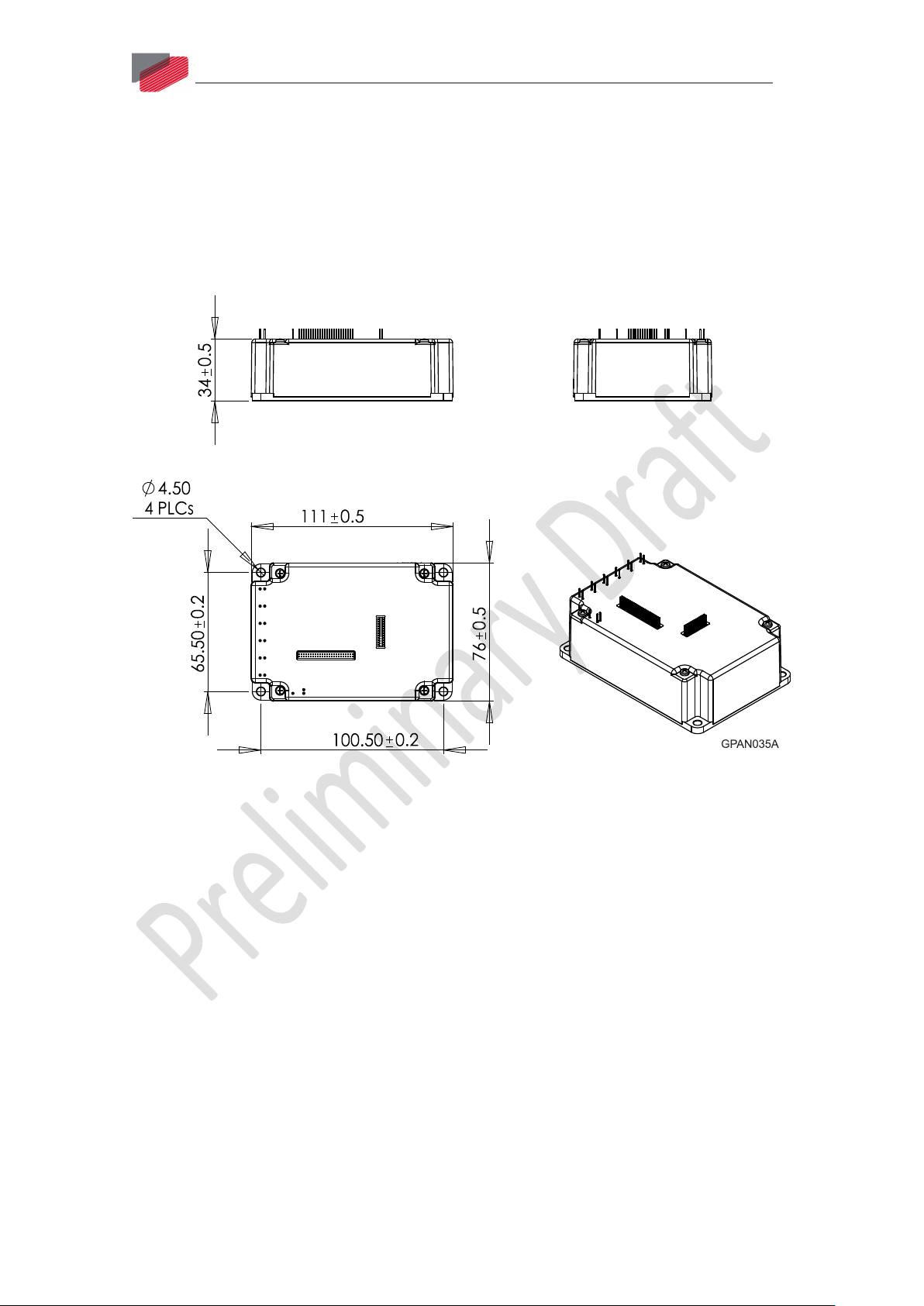
• 7 mA for TTL models
Programmable digital output 4:
23 OUT4
• 250 mA for PLC models
• 7 mA for TTL models
26 VDD Supply for outputs 1 to 4
25 VDDRET Supply return for outputs 1 to 4
Table 16: Digital Output Pin Assignment
See Figure 24 for the PLC option connection and Figure 25 for the TTL option connection.
|User I/Os|www.elmomc.com
Page 49

Gold Panther Installation Guide
Table of Contents
MAN-G-PANIG -EC (Ver. 1.000)
49
Figure 24: Digital Output Connection Diagram – PLC Option for S or 0 Suffixes
|User I/Os|www.elmomc.com
Page 50

Gold Panther Installation Guide
Table of Contents
MAN-G-PANIG -EC (Ver. 1.000)
50
Figure 25: Digital Output Connection Diagram – TTL Option for T or 1 Suffixes
|User I/Os|www.elmomc.com
Page 51
Gold Panther Installation Guide
Table of Contents
MAN-G-PANIG -EC (Ver. 1.000)
51
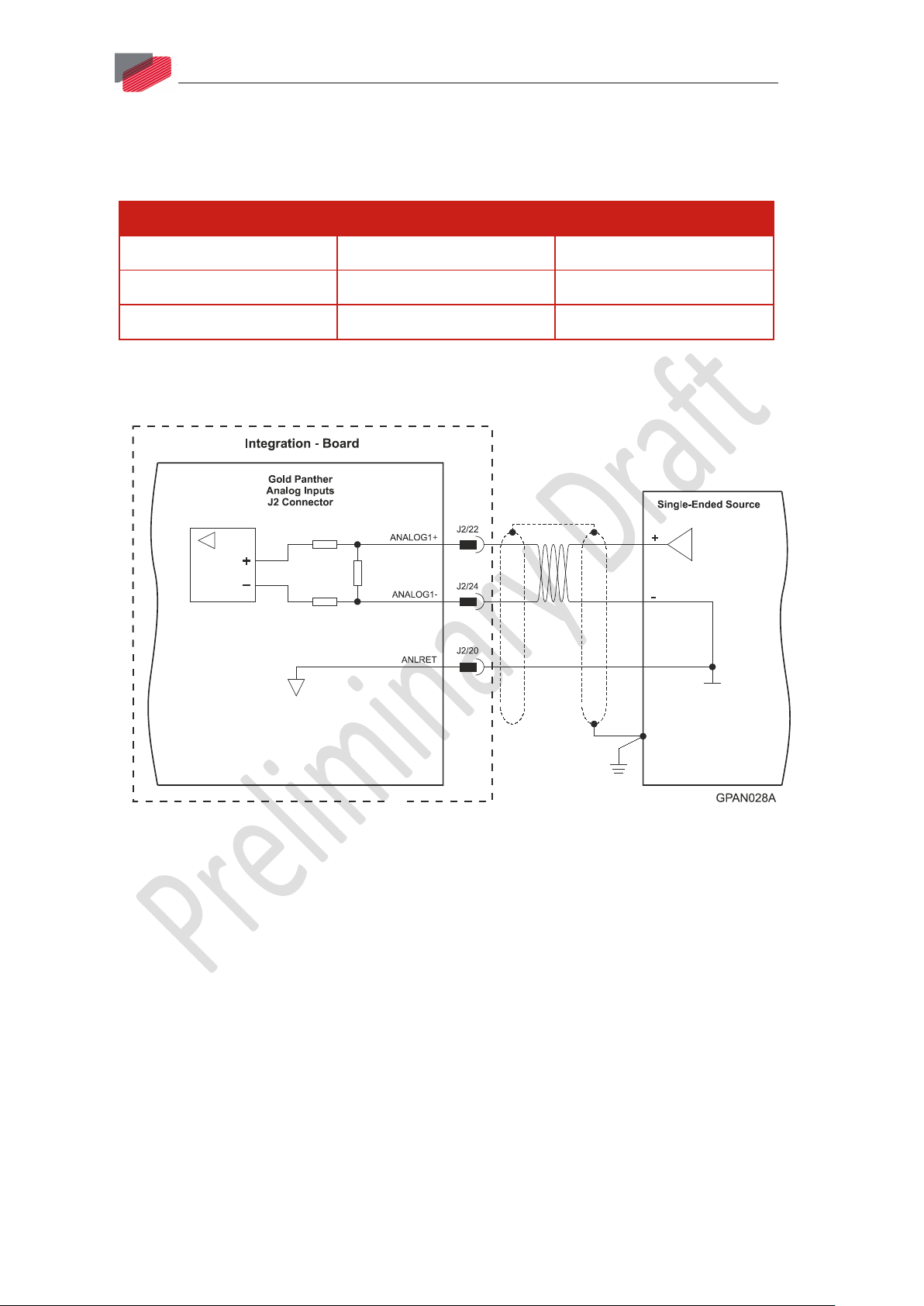
5.4.3. Input (J2)
An analog user input can be configured by software to be used as either tachometer velocity sensor
input or potentiometer position feedback.
Pin (J2) Signal Function
22 ANALOG1+ Analog input 1+
24 ANALOG1- Analog input 1-
20 ANLRET Analog ground
Table 17: Analog Input Pin Assignment
Figure 26: Analog Input with Single-Ended Source
|User I/Os|www.elmomc.com
Page 52

Gold Panther Installation Guide
Table of Contents
MAN-G-PANIG -EC (Ver. 1.000)
5.5. Communications
The communication interface may differ according to the user’s hardware. The Gold Panther can
communicate using the following options:
Standard EtherCAT
G-PANXXX/YYYSXX G-PANXXX/YYYEXX
CAN EtherCAT
USB 2.0 USB 2.0
Table 18: Gold Panther Communication Options
For ease of setup and diagnostics of CAN communication, and CAN can be used simultaneously.
Note: When the EtherCAT is connected, and FoE in operation, the USB cable connection must
be disconnected.
52
5.5.1. CAN Communication (J2)
In order to benefit from CAN communication, the user must have an understanding of the basic
programming and timing issues of a CAN network.
To connect the CAN communication cable:
6. Connect the shield to the ground of the host (PC). Usually, this connection is soldered internally
inside the connector at the PC end. You can use the drain wire to facilitate connection.
7. Ensure that the shield of the cable is connected to the shield of the connector used for
communications. The drain wire can be used to facilitate the connection.
8. Make sure to have a 120-Ohm resistor termination at each of the two ends of the network
cable.
9. The Gold Panther’s CAN port is non-isolated.
Pin (J2) Signal Function
31, 32 CAN_COMRET CAN Communication Return
38 CAN_L CAN_L bus line (dominant low)
40 CAN_H CAN_H bus line (dominant high)
Table 19: CAN Pin Assignments
|Communications|www.elmomc.com
Page 53

Gold Panther Installation Guide
Table of Contents
MAN-G-PANIG -EC (Ver. 1.000)
53
Figure 27: CAN Network Diagram
Caution: When installing CAN communication, ensure that each servo drive is
allocated a unique ID. Otherwise, the CAN network may “hang”.
|Communications|www.elmomc.com
Page 54

Gold Panther Installation Guide
Table of Contents
MAN-G-PANIG -EC (Ver. 1.000)
54
5.5.2. USB 2.0 Communication (J2)
The USB network consists of a Host controller and multiple devices. The Gold Panther is a USB
device.
To connect the USB communication cable:
1. Connect the shield to the ground of the host (PC). Usually, this connection is soldered internally
inside the connector at the PC end. You can use the drain wire to facilitate connection.
2. Ensure that the shield of the cable is connected to the shield of the connector used for
communications. The drain wire can be used to facilitate the connection.
Pin (J2) Signal Function
44 USB VBUS USB VBUS 5 V
43 USB COMRET USB Communication return
41 USBD- USB _N line
42 USBD+ USB _P line
Table 20: USB 2.0 Pin Assignments
Figure 28: USB Network Diagram
|Communications|www.elmomc.com
Page 55

Gold Panther Installation Guide
Table of Contents
MAN-G-PANIG -EC (Ver. 1.000)
5.5.3. EtherCAT Communication (J2)
To use EtherCAT and Ethernet communication with the Gold Panther, it is required to use an
isolation transformer. The most common solution is to use RJ-45 connectors that include
transformer isolation.
This section describes how to connect the Gold Panther’s EtherCAT interface using the above
mentioned connectors.
Notes for EtherCAT communication:
1. The EtherCAT IN port can be configured as an Ethernet port for TCP/IP – see the EtherCAT
Manual.
2. It is recommended to use CAT5e (or higher) cable. Category 5e cable is a high signal integrity
cable with four twisted pairs.
Pin (J2) Signal Function
26 3.3 V 3.3 V for EtherCAT LEDs
55
31, 32 PHY_IN_COMRET EtherCAT Communication Return
27 PHY_IN_RX+ EtherCAT IN RX+ Line
29 PHY_IN_RX- EtherCAT IN RX- Line
33 PHY_IN_TX+ EtherCAT IN TX+ Line
35 PHY_IN_TX- EtherCAT IN TX- Line
39 PHY_IN_SPEED Indicates EtherCAT Speed
37 PHY_IN_LINK_ACT Indicates EtherCAT LINK
31, 32 PHY_OUT COMRET EtherCAT Communication return
28 PHY_ OUT _RX+ EtherCAT OUT RX+ Line
30 PHY_ OUT _RX- EtherCAT OUT RX- Line
34 PHY_ OUT _TX+ EtherCAT OUT TX+ Line
36 PHY_ OUT _TX- EtherCAT OUT TX- Line
40 PHY_ OUT _SPEED Indicates EtherCAT Speed
38 PHY_ OUT_LINK_ACT Indicates EtherCAT LINK
Table 21: EtherCAT - Pin Assignments
|Communications|www.elmomc.com
Page 56

Gold Panther Installation Guide
Table of Contents
MAN-G-PANIG -EC (Ver. 1.000)
56
Figure 29: EtherCAT Connection Schematic Diagram
|Communications|www.elmomc.com
Page 57

Gold Panther Installation Guide
Table of Contents
MAN-G-PANIG -EC (Ver. 1.000)
57
Note: The diagram above ignores line interface for simplicity.
When connecting several EtherCAT devices in a network, the EtherCAT master must always be the
first device in the network. The output of each device is connected to the input of the next device.
The output of the last device may remain disconnected. If redundancy is required, the output of the
last device should be connected to the input of the EtherCAT master.
Figure 30: EtherCAT Network with no Redundancy
Figure 31: EtherCAT Network with Redundancy
5.5.4. Ethernet Communication (J2)
To use EtherCAT and Ethernet communication with the Gold Panther, it is required to use an
isolation transformer. The most common solution is to use RJ-45 connectors that include
transformer isolation.
This section describes how to connect the Gold Panther Ethernet interface using the above
mentioned connectors.
For other available options, please see Section 5.5.5.
To initiate Ethernet communication:
1. The EtherCAT IN port can be configured as an Ethernet port for TCP/IP – see the EtherCAT
Manual.
2. It is recommended to use CAT5e (or higher) cable. Category 5e cable is a high signal integrity
cable with four twisted pairs.
|Communications|www.elmomc.com
Page 58

Gold Panther Installation Guide
Table of Contents
MAN-G-PANIG -EC (Ver. 1.000)
Pin (J2) Signal Function
26 3.3 V 3.3 V for Ethernet LEDs
27 PHY_IN_RX+ Ethernet RX + Line
29 PHY_IN_RX- Ethernet RX – Line
31, 32 Ethernet COMRET Ethernet Communication return
33 PHY_IN_TX+ Ethernet TX + Line
35 PHY_IN_TX- Ethernet TX – Line
39 PHY_IN_SPEED Indicates Ethernet Speed
37 PHY_IN_LINK_ACT Indicates Ethernet LINK
Table 22: Ethernet - Pin Assignments
58
Figure 32: Ethernet Network Schematic Diagram
Note: The diagram above ignores line interface for simplicity.
|Communications|www.elmomc.com
Page 59

Gold Panther Installation Guide
Table of Contents
MAN-G-PANIG -EC (Ver. 1.000)
59
5.5.5. EtherCAT/Ethernet Line Interface
Ethernet transceivers require either isolation transformers or capacitor coupling for proper
functioning. The Gold Panther unit does not include such isolation, therefore you must take this into
consideration when designing the integration board.
In Sections 5.5.3 and 5.5.4, a schematic connection with a standard RJ-45 connector that includes
transformer isolation is described.
Other recommended connection options are:
• Gold Panther to an RJ-45 connector without an integrated magnetic isolation (e.g., M12
connectors) – an isolation transformer is required.
• Connecting two EtherCAT ports on the same board can be done using capacitive coupling or
transformer coupling.
For more detailed explanations, including layout recommendations and component selection
guidelines contact Elmo’s technical support.
|Communications|www.elmomc.com
Page 60

Gold Panther Installation Guide
Table of Contents
Chapter 6: Powering Up
MAN-G-PANIG -EC (Ver. 1.000)
60
After the Gold Panther is connected to its peripheral devices, it is ready to be powered up.
Caution: Before applying power, ensure that
1. The DC supply is within the specified range.
2. The proper plus-minus connections are in order.
3. The VN- is not connected to the PE nor to the Neutral, when working with a
non-isolated power supply.
6.1. Initializing the System
After the Gold Panther has been connected and mounted, the system must be set up and initialized.
This is accomplished using the Elmo Application Studio, Elmo’s Windows-based software
application. Install the application and then perform setup and initialization according to the
directions in the Elmo Application Studio II User’s Manual.
|Initializing the System|www.elmomc.com
Page 61
Gold Panther Installation Guide
Table of Contents
Chapter 7: Heat Dissipation
MAN-G-PANIG -EC (Ver. 1.000)
61
The best way to dissipate heat from the Gold Panther is to mount it so that its heat-sink faces up.
For best results leave approximately 10 mm of space between the Gold Panther‘s heat-sink and any
other assembly.
7.1. Gold Panther Thermal Data
• Heat dissipation capability (θ): approximately 5.5 °C/W
• Thermal time constant: approximately 600 seconds (thermal time constant means that the Gold
Panther will reach 2/3 of its final temperature after 10 minutes)
• Shut-off temperature: 86 °C to 88 °C (measured on the heat-sink)
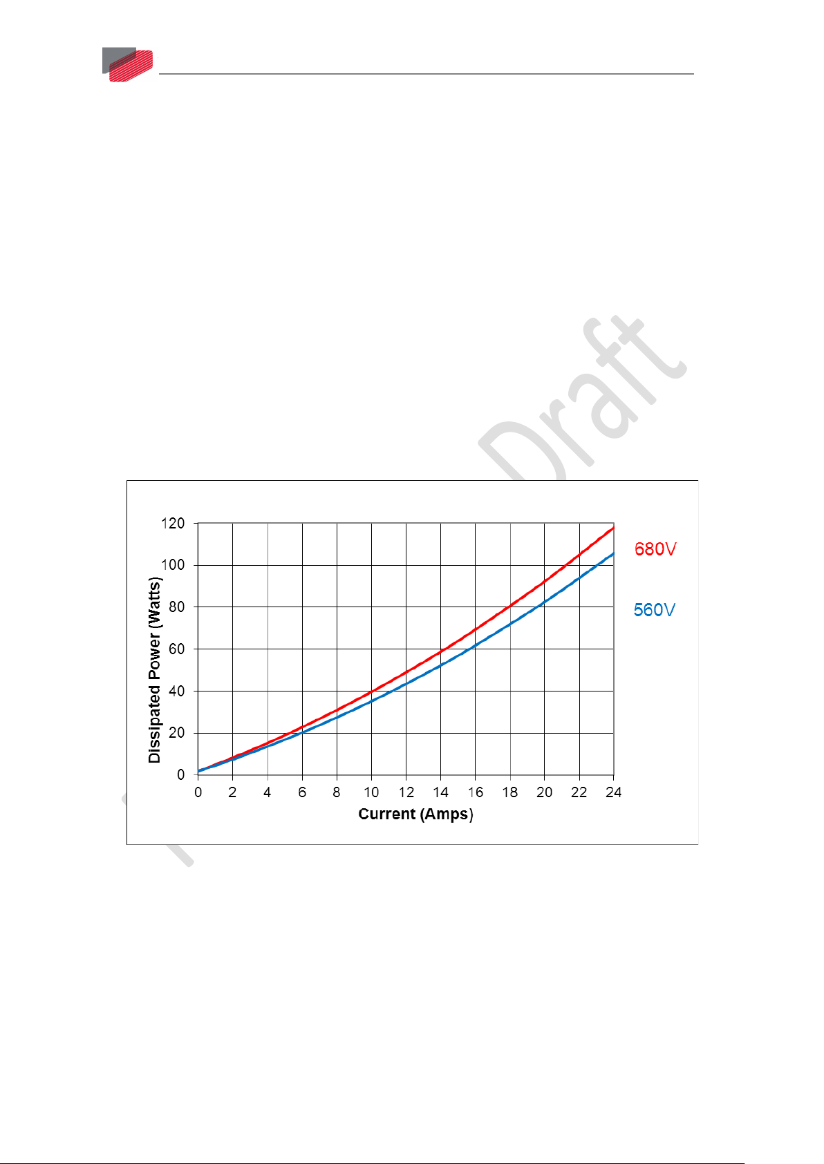
7.2. Heat Dissipation Data
Heat Dissipation is shown graphically below:
Figure 33: Dissipation versus Current Graph for 560 and 680 VDC
|Gold Panther Thermal Data|www.elmomc.com
Page 62

Gold Panther Installation Guide
Table of Contents
MAN-G-PANIG -EC (Ver. 1.000)
62
Figure 34: Dissipation versus Current Graph for 330 VDC
7.3. How to Use the Charts
The power dissipation in the chart includes the losses of the rectifying bridge.
Regarding Figure 33 and Figure 34, the following should be noted:
DC Bus Voltage (VDC) Rectified Voltage (VAC)
560 3X400
680 3X480
330 3X230
The charts above are based upon theoretical worst-case conditions. Actual test results show 30% to
50% better power dissipation.
To determine if your application needs a heat sink:
1. Allow maximum heat sink temperature to be 80 °C or less (shunt down is 6 °C to 8 °C
higher).
2. Determine the ambient operating temperature of the Gold Panther as ≤ 40 °C.
3. Calculate the allowable temperature increase according to the following example: For an
ambient temperature of 40 °C, ΔT = 80 to 40°C = 40°C
4. Use the chart to find the actual dissipation power of the drive. Follow the voltage curve to
the desired output current and then find the dissipated power.
|How to Use the Charts|www.elmomc.com
Page 63
Gold Panther Installation Guide
Table of Contents
Chapter 8: Dimensions
MAN-G-PANIG -EC (Ver. 1.000)
This chapter provides detailed technical information regarding the Gold Panther.
63
|How to Use the Charts|www.elmomc.com
Page 64

Table of Contents
|How to Use the Charts|www.elmomc.com
 Loading...