

Page 1

Table of Contents
Gold Eagle
Digital Servo Drive
Installation Guide
June 2014 (Ver. 1.000) www.elmomc.com
||Warnings|www.elmomc.com
Page 2
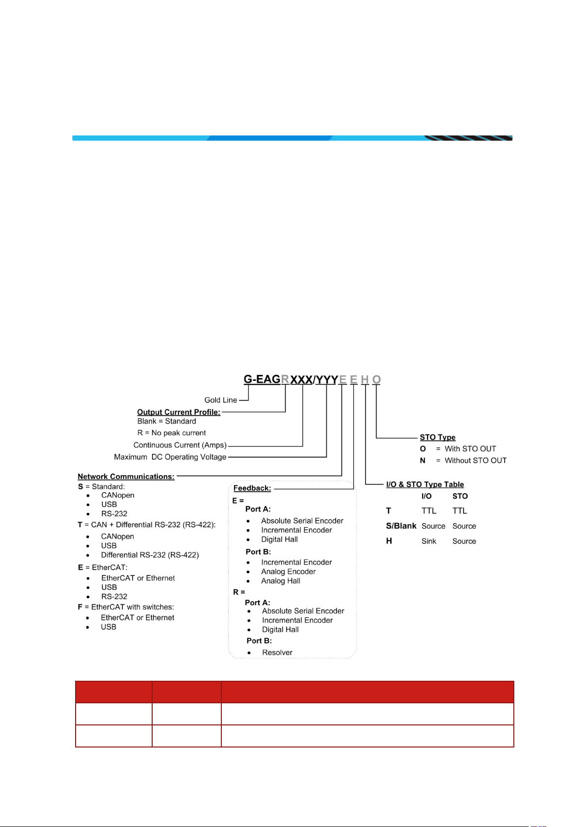
Table of Contents
Notice
This guide is delivered subject to the following conditions and restrictions:
• This guide contains proprietary information belonging to Elmo Motion Control Ltd. Such
information is supplied solely for the purpose of assisting users of the Gold Drum servo drive in
its installation.
• The text and graphics included in this manual are for the purpose of illustration and reference
only. The specifications on which they are based are subject to change without notice.
• Information in this document is subject to change without notice.
Document no. MAN-G-EAGIG-EC (Ver. 1.000)
Copyright 2014
Elmo Motion Control Ltd.
All rights reserved.
Catalog Number
Revision History
Version Date Details
Ver. 1.000 June 2014 Initial document
||Warnings|www.elmomc.com
Page 3

Table of Contents
Table of Contents
MAN-G-EAGIG-EC (V er. 1.000)
Chapter 1: This Installation Guide ..................................................................................... 5
Chapter 2: Safety Information .......................................................................................... 5
2.1. Warnings ........................................................................................................................ 6
2.2. Cautions .......................................................................................................................... 6
2.3. CE Marking Conformance ............................................................................................... 6
2.4. Warranty Information .................................................................................................... 6
Chapter 3: Product Description ......................................................................................... 7
Chapter 4: Technical Information ...................................................................................... 8
4.1. Environment Conditions ................................................................................................. 8
4.2. Physical Specifications .................................................................................................... 9
4.3. Technical Data ................................................................................................................ 9
4.3.1. VL Logic Supply .............................................................................................. 10
4.3.2. Product Features ........................................................................................... 10
3
Chapter 5: Unpacking the Drive Components .................................................................. 11
Chapter 6: Gold Eagle Connectors and Indicators ............................................................ 12
6.1. Connector Types ........................................................................................................... 12
Chapter 7: Mounting the Gold Eagle ............................................................................... 14
Chapter 8: Gold Eagle Connection Diagrams .................................................................... 15
Chapter 9: Wiring ........................................................................................................... 17
9.1. Introduction .................................................................................................................. 17
9.2. Basic Recommendations .............................................................................................. 19
9.2.1. General .......................................................................................................... 19
9.2.2. Feedback Cable Port A and Port B Connector ............................................... 20
9.2.3. Feedback Cable Port C Connector ................................................................. 21
9.2.4. IO Cable Connector ........................................................................................ 21
9.2.5. STO (Port C) Cable Connector ........................................................................ 22
9.3. Motor Power Connector Pinouts ................................................................................. 23
9.4. Main Power Input and Motor Connections.................................................................. 25
9.5. Connecting the DC Power and the Motor Power Cables ............................................. 26
9.6. Main Power .................................................................................................................. 27
9.6.1. Power Supply Connections ............................................................................ 27
9.6.1.1. Gold Drum Power Supply Connections ........................................ 28
9.6.1.2. Multiple Connections Topology .................................................... 28
9.7. VL Logic Supply(P2) ....................................................................................................... 29
9.7.1. VL Logic Supply(P2) ........................................................................................ 29
||Warnings|www.elmomc.com
Page 4

Table of Contents
Table of Contents
MAN-G-EAGIG-EC (V er. 1.000)
9.8. Drive Status Indicator ................................................................................................... 30
9.9. Port A and Port B (P1)................................................................................................... 31
9.9.1. Incremental Encoder(P1) ............................................................................... 33
9.9.2. Hall Sensor(P1) .............................................................................................. 33
9.9.3. Absolute Serial Type Encoder(P1) ................................................................. 34
9.9.4. Interpolated Analog Encoder(P1) .................................................................. 36
9.9.5. Resolver(P1) ................................................................................................... 37
9.10. Port C Connector - Port C, Analog, and STO (P3) ......................................................... 38
9.10.1. Port C(P3) ....................................................................................................... 40
9.10.2. Analog Input(P3) ............................................................................................ 40
9.10.3. STO(P3) .......................................................................................................... 41
9.10.3.1. Source Mode PLC Voltage Level Input .......................................... 41
9.10.3.2. TTL Mode TTL Voltage Level Input ............................................... 41
9.10.3.3. SINK Mode – PLC Voltage Level Input .......................................... 42
9.10.3.4. STO Output(P2) ............................................................................. 43
9.11. Digital Inputs and Outputs (P2) .................................................................................... 44
9.11.1. Digital Input and Output TTL Mode(P2) ........................................................ 46
9.11.2. Digital Input and Output PLC Source Mode(P2) ............................................ 48
9.11.3. Digital Input and Output Sink Mode(P2) ....................................................... 50
9.12. Communications (P4) ................................................................................................... 52
9.12.1. USB 2.0(P4) .................................................................................................... 55
9.12.2. EtherCAT Communications Version .............................................................. 56
9.12.2.1. EtherCAT Wiring(P4) ..................................................................... 56
9.12.2.2. EtherCAT Status Indicator............................................................. 57
9.12.2.3. EtherCAT Address Switches .......................................................... 58
9.12.3. CAN Communications Version ....................................................................... 59
9.12.3.1. CAN Wiring(P4) ............................................................................. 59
9.12.4. RS-232(P4) ..................................................................................................... 61
9.12.5. RS-422 (Differential RS-232) Communication(P4) ......................................... 62
4
Chapter 10: Powering Up ................................................................................................. 63
10.1. Initializing the System .................................................................................................. 63
Chapter 11: Heat Dissipation ............................................................................................ 64
11.1. Gold Eagle Thermal Data .............................................................................................. 64
11.2. Heat Dissipation Data ................................................................................................... 65
11.3. How to Use the Charts ................................................................................................. 66
Chapter 12: Gold Eagle Dimensions .................................................................................. 67
||Warnings|www.elmomc.com
Page 5
Gold Eagle Installation Guide
Table of Contents
Chapter 1: This Installation Guide
Chapter 2:
Safety Information
Warning:
Caution:
Important:
MAN-G-EAGIG-EC (Ver. 1.000)
This installation Guide details the technical data, pinouts, and power connectivity of the Gold Eagle.
For a comprehensive detailed description of the functions refer to the MAN-G-Panel Mounted
Drives Hardware manual which describes Panel Mounted products.
5
In order to achieve the optimum, safe operation of the Gold Eagle, it is imperative that you
implement the safety procedures included in this installation guide. This information is provided to
protect you and to keep your work area safe when operating the Gold Eagle and accompanying
equipment.
Please read this chapter carefully before you begin the installation process.
Before you start, ensure that all system components are connected to earth ground. Electrical
safety is provided through a low-resistance earth connection.
Only qualified personnel may install, adjust, maintain and repair the servo drive. A qualified person
has the knowledge and authorization to perform tasks such as transporting, assembling, installing,
commissioning and operating motors.
The Gold Eagle contains electrostatic-sensitive components that can be damaged if handled
incorrectly. To prevent any electrostatic damage, avoid contact with highly insulating materials,
such as plastic film and synthetic fabrics. Place the product on a conductive surface and ground
yourself in order to discharge any possible static electricity build-up.
To avoid any potential hazards that may cause severe personal injury or damage to the product
during operation, keep all covers and cabinet doors shut.
The following safety symbols are used in this and all Elmo Motion Control manuals:
This information is needed to avoid a safety hazard, which might cause bodily injury
or death as a result of incorrect operation.
This information is necessary to prevent bodily injury, damage to the product or to
other equipment.
Identifies information that is critical for successful application and understanding of
the product.
||Warnings|www.elmomc.com
Page 6
Gold Eagle Installation Guide
Table of Contents
MAN-G-EAGIG-EC (Ver. 1.000)
6
2.1. Warnings
• To avoid electric arcing and hazards to personnel and electrical contacts, never
connect/disconnect the servo drive while the power source is on.
• Power cables can carry a high voltage, even when the motor is not in motion. Disconnect
the Gold Eagle from all voltage sources before servicing.
• The high voltage products within the Gold Line range contain grounding conduits for electric
current protection. Any disruption to these conduits may cause the instrument to become
hot (live) and dangerous.
• After shutting off the power and removing the power source from your equipment, wait at
least 1 minute before touching or disconnecting parts of the equipment that are normally
loaded with electrical charges (such as capacitors or contacts). Measuring the electrical
contact points with a meter, before touching the equipment, is recommended.
2.2. Cautions
• The maximum DC power supply connected to the instrument must comply with the
parameters outlined in this guide.
• When connecting the Gold Eagle to an approved isolated auxiliary power supply, connect it
through a line that is separated from hazardous live voltages using reinforced or double
insulation in accordance with approved safety standards.
• Before switching on the Gold Eagle, verify that all safety precautions have been observed
and that the installation procedures in this manual have been followed.
• Make sure that the Safe Torque Off is operational
2.3. CE Marking Conformance
The Gold Eagle is intended for incorporation in a machine or end product. The actual end product
must comply with all safety aspects of the relevant requirements of the European Safety of
Machinery Directive 2006/42/EC as amended, and with those of the most recent versions of
standards EN 60204-1 and
Concerning electrical equipment designed for use within certain voltage limits, the Gold Eagle
meets the provisions outlined in 2006/95/EC. The party responsible for ensuring that the
equipment meets the limits required by EMC regulations is the manufacturer of the end product.
EN ISO 12100 at the least, and in accordance with 2006/95/EC.
2.4. Warranty Information
The products covered in this manual are warranted to be free of defects in material and
workmanship and conform to the specifications stated either within this document or in the
product catalog description. All Elmo drives are warranted for a period of 12 months from the time
of installation, or 18 months from time of shipment, whichever comes first. No other warranties,
expressed or implied — and including a warranty of merchantability and fitness for a particular
purpose — extend beyond this warranty.
||Warnings|www.elmomc.com
Page 7

Gold Eagle Installation Guide
Table of Contents
Chapter 3: Product Description
MAN-G-EAGIG-EC (Ver. 1.000)
7
The Gold Eagle series is a standard "off-the-shelf" series of durable servo drives designed, verified,
manufactured and tested for applications operating under extreme environmental conditions. The
Gold Eagle delivers up to 8.0 kW of continuous /16.0 kW peak power , and 9.6 kW of continuous
power with R type drives, in a compact package.
This advanced, high power density servo drive operates from a DC power source in current, velocity,
position and advanced position modes, in conjunction with a permanent-magnet synchronous
brushless motor, DC brush motor, linear motor or voice coil. They are designed for use with any
type of sinusoidal and trapezoidal commutation, with vector control. The Gold Eagle can operate as
a stand-alone device or as part of a multi-axis system in a distributed configuration on a real-time
network.
The drives are easily set up and tuned using Elmo Application Studio software tools. This Windowsbased application enables users to quickly and simply configure the servo drive for optimal use with
their motor. The Gold Eagle, as part of the Gold Line, is fully programmable with Elmo’s motion
control language.
Since the power stage is fully isolated from the control stage, the DC rectifier can be fed directly
from the mains, without the need for a bulky and expensive transformer.
The Gold Eagle is available in a variety of options. There are multiple power rating options, two
different communications options, a variety of feedback selections and I/O configuration
possibilities.
||Warranty Information|www.elmomc.com
Page 8

Gold Eagle Installation Guide
Table of Contents
Chapter 4: Technical Information
MAN-G-EAGIG-EC (Ver. 1.000)
This chapter describes the relevant technical data applicable to the Gold Eagle servo drive. For
further details of the Gold ExtrIQ Line EMC and Safety standards, refer to the MAN-G-Panel
Mounted Drives Hardware Manual Chapter 15: Gold Line Standards.
4.1. Environment Conditions
The ExtrIQ products are designed, manufactured and tested to meet extreme environmental
conditions. The ExtrIQ durability is qualified, verified and tested according to the most severe
environmental, EMC and safety standards exceeding the traditional and senior military
Standards.
The ExtrIQ series of drives support the following extended environmental conditions.
8
Feature Operation Conditions Range
Ambient
Non-operating conditions -50 °C to +100 °C (-58 °F to 212 °F)
Temperature
Range
Temperature
Shock
Altitude
Operating conditions -40 °C to +70 °C (-40 °F to 160 °F)
Non-operating conditions -40 °C to +70 °C (-40 °F to 160 °F)
within 3 min
Non-operating conditions Unlimited
Operating conditions -400 m to 12,000 m (-1312 to 39370 feet)
Maximum
Humidity
Non-operating conditions Up to 95% relative humidity
non-condensing at 35 °C (95 °F)
Operating conditions Up to 95% relative humidity non-
condensing at 25 °C (77 °F), up to 90%
relative humidity non-condensing at 42 °C
(108 °F)
Vibration
Mechanical
Shock
Operating conditions 20 Hz to 2,000 Hz, 14.6g
Non-operating conditions ±40g; Half sine, 11 msec, 3 per direction
(overall 18)
Operating conditions ±20g; Half sine, 11 msec, 3 per direction
(overall 18)
||Environment Conditions|www.elmomc.com
Page 9
Gold Eagle Installation Guide
Table of Contents
MAN-G-EAGIG-EC (Ver. 1.000)
4.2. Physical Specifications
Feature Units All Types
Weight g (oz) 700 g (24.7 oz)
Dimensions mm (in) 134 x 95 x 72 (5.3" x 3.7" x 2.84")
Mounting method Wall/Panel Mount
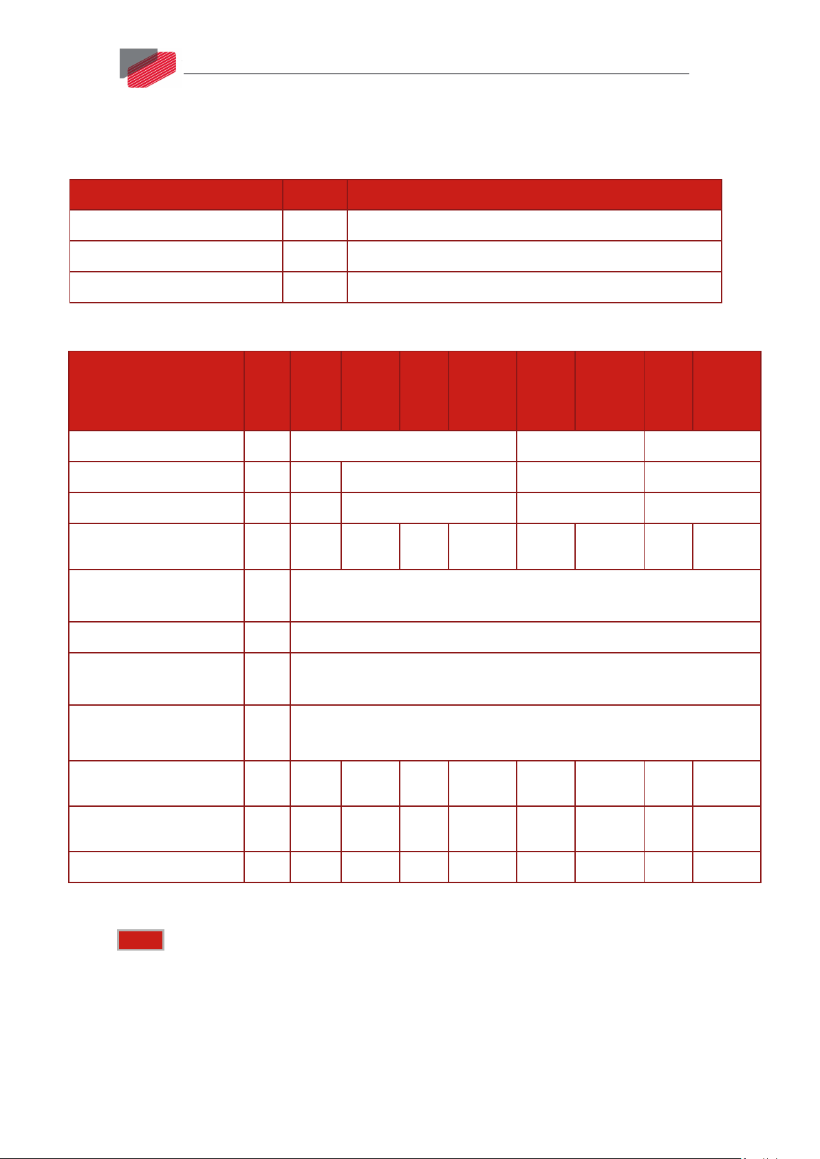
4.3. Technical Data
Feature
Units
70/60
Minimum supply voltage VDC 14 46 92
50/100
100/100
R150/100
35/200
R60/200
18/400
9
R26/400
Nominal supply voltage VDC 50 85 170 340
Maximum supply voltage VDC 59 95 195 390
Maximum continuous
W 3400 4000 8000 12000 5600 9600 5600 11500
power output
Efficiency at rated power
% > 99
(at nominal conditions)
Max output voltage 97% of DC bus voltage at f=22 kHz
VL Logic supply input
VDC 14 to 72
voltage
VL Logic supply input
power
Amplitude sinusoidal/DC
VA ≤ 4 VA without external loading of 5V (Encoders)
≤ 6 VA with full external loading of 5V (2 encoders)
A 70 50 100 150 35 60 18 26
continuous current
Sinusoidal continuous
A 50 35 70 106 25 42 12.7 18.4
RMS current limit (Ic)
Peak current limit A 2 x Ic 2 x Ic 2 x Ic No Peak 2 x Ic No Peak 2 x Ic No Peak
Table 1: Power Ratings
Notes: The current ratings of the Gold Eagle are given in units of DC amperes (ratings
that are used for trapezoidal commutation or DC motors). The RMS (sinusoidal commutation)
value is the DC value divided by 1.41.
The “Minimum supply voltage” of the XXX/100 is 14 VDC, to allow operation at 24 VDC with
the 100 VDC products.
The VL of the XXX/100 is 14 – 72 VDC, to improve the ruggedness of the products and to allow
more flexibility with the VL.
||Physical Specifications|www.elmomc.com
Page 10

Gold Eagle Installation Guide
Table of Contents
MAN-G-EAGIG-EC (Ver. 1.000)
4.3.1. VL Logic Supply
Feature Details
Logic power supply Isolated DC source only
Logic supply input voltage 14 to 72 VDC
Logic supply input power ≤ 4 VA without external loading of 5V (Encoders)
≤ 6 VA with full external loading of 5V (2 Encoders)
The Gold Eagle is available in a variety of options. There are multiple power rating options, two
different communications options, a variety of feedback selections and I/O configuration
possibilities.
4.3.2. Product Features
10
Main Feature Details Presence and No.
STO
TTL or √
PLC Source √
Digital Input
Option
TTL or 6
PLC Source or 6
PLC Sink 6
Digital Output
Option
TTL or 4
PLC Source or 4
PLC Sink 4
Analog Input
Feedback
Communication
Option
Differential ±10V 1
Standard Port A, B, & C √
USB √
EtherCAT √
CAN √
RS-232 √
Differential RS-232 (RS-422) √
||Technical Data|www.elmomc.com
Page 11
MAN-G-EAGIG-EC (Ver. 1.000)
Table of Contents
Chapter 5: Unpacking the Drive Components
Gold Eagle Installation Guide
11
Before you begin working with the Gold Eagle, verify that you have all of its components, as follows:
• The Gold Eagle servo drive
• The Elmo Application Studio (EASII) software and software manual
The Gold Eagle is shipped in a cardboard box with Styrofoam protection.
To unpack the Gold Eagle:
1. Carefully remove the servo drive from the box and the Styrofoam.
2. Check the drive to ensure that there is no visible damage to the instrument. If any damage
has occurred, report it immediately to the carrier that delivered your drive.
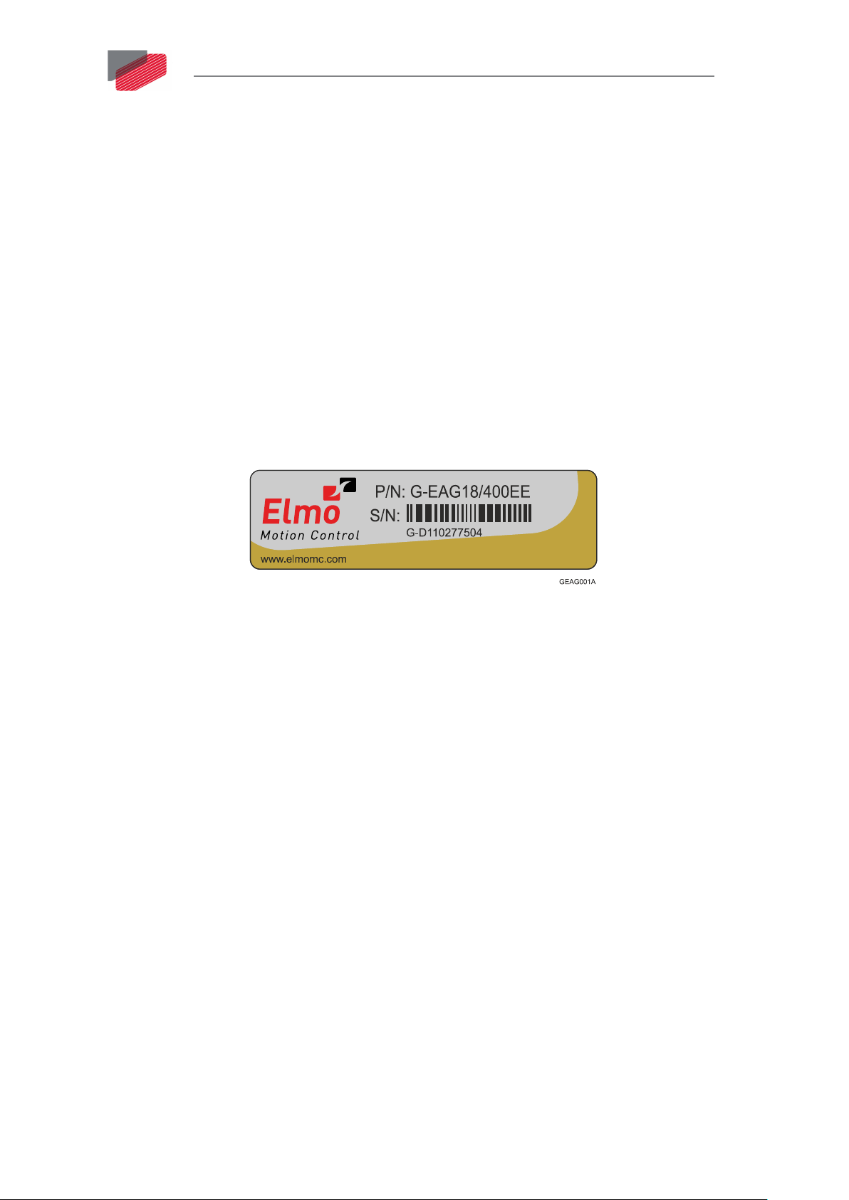
3. To ensure that the Gold Eagle you have unpacked is the appropriate type for your
requirements, locate the part number sticker on the side of the Gold Eagle. It looks like this:
4. Verify that the Gold Eagle type is the one that you ordered, and ensure that the voltage
meets your specific requirements.
The part number at the top provides the type designation. Refer to the appropriate part
number in the section Catalog Number at the beginning of the installation guide.
||Technical Data|www.elmomc.com
Page 12
Gold Eagle Installation Guide
Table of Contents
Chapter 6: Gold Eagle Connectors and Indicators
MAN-G-EAGIG-EC (Ver. 1.000)
6.1. Connector Types
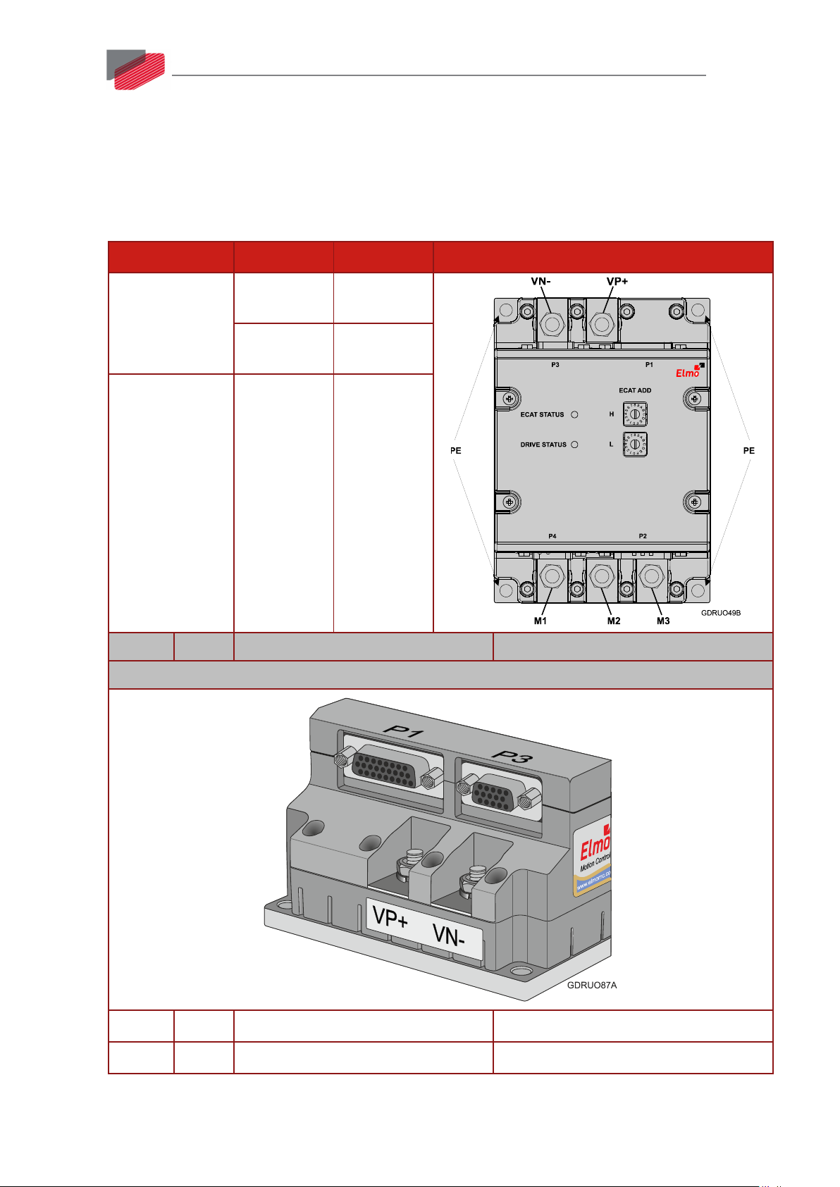
The Gold Eagle has four connector types as follows:
12
Type
Barrel Connector
+ M6 Spring
Washer + M6 Nut
Barrel Connector
+ M5 Flat Washer
+ M5 Spring
Washer + M5
screw
Pins
Name Type Function
Function
Port
Power VP+, VN-
Motor M1, M2, M3
Earth
PE, PE, PE, PE
Connection
Connector Location
Rear Connectors
15 P3 D-Type High Density, female Port C, Analog and STO
26 P1 D-Type High Density, female Port A and Port B
||Connector Types|www.elmomc.com
Page 13
Gold Eagle Installation Guide
Table of Contents
MAN-G-EAGIG-EC (Ver. 1.000)
13
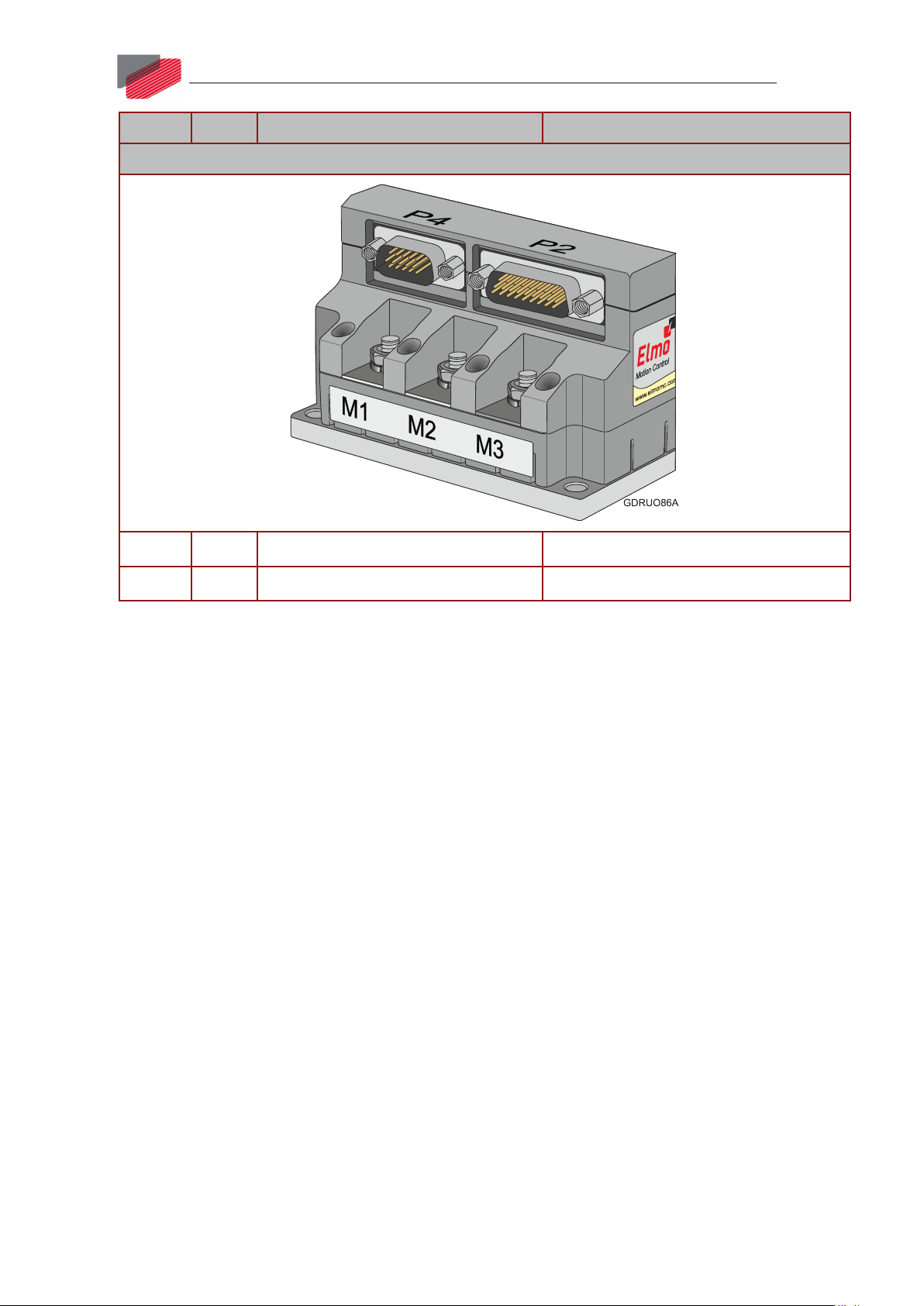
Pins
Name Type Function
Front Connectors
15 P4 D-Type, High Density, male Communications
26 P2 D-Type, High Density, male I/Os
||Connector Types|www.elmomc.com
Page 14
Gold Eagle Installation Guide
Table of Contents
Chapter 7: Mounting the Gold Eagle
MAN-G-EAGIG-EC (Ver. 1.000)
The Gold Drum has been designed for standard mounting by wall mounting along the back.
Use M5 round head screws, one through each opening in the heat sink, to mount the Gold Drum
(see the diagrams below).
14
Figure 1: Mounting the Gold Eagle
||Connector Types|www.elmomc.com
Page 15
Gold Eagle Installation Guide
Table of Contents
Chapter 8: Gold Eagle Connection Diagrams
MAN-G-EAGIG-EC (Ver. 1.000)
15
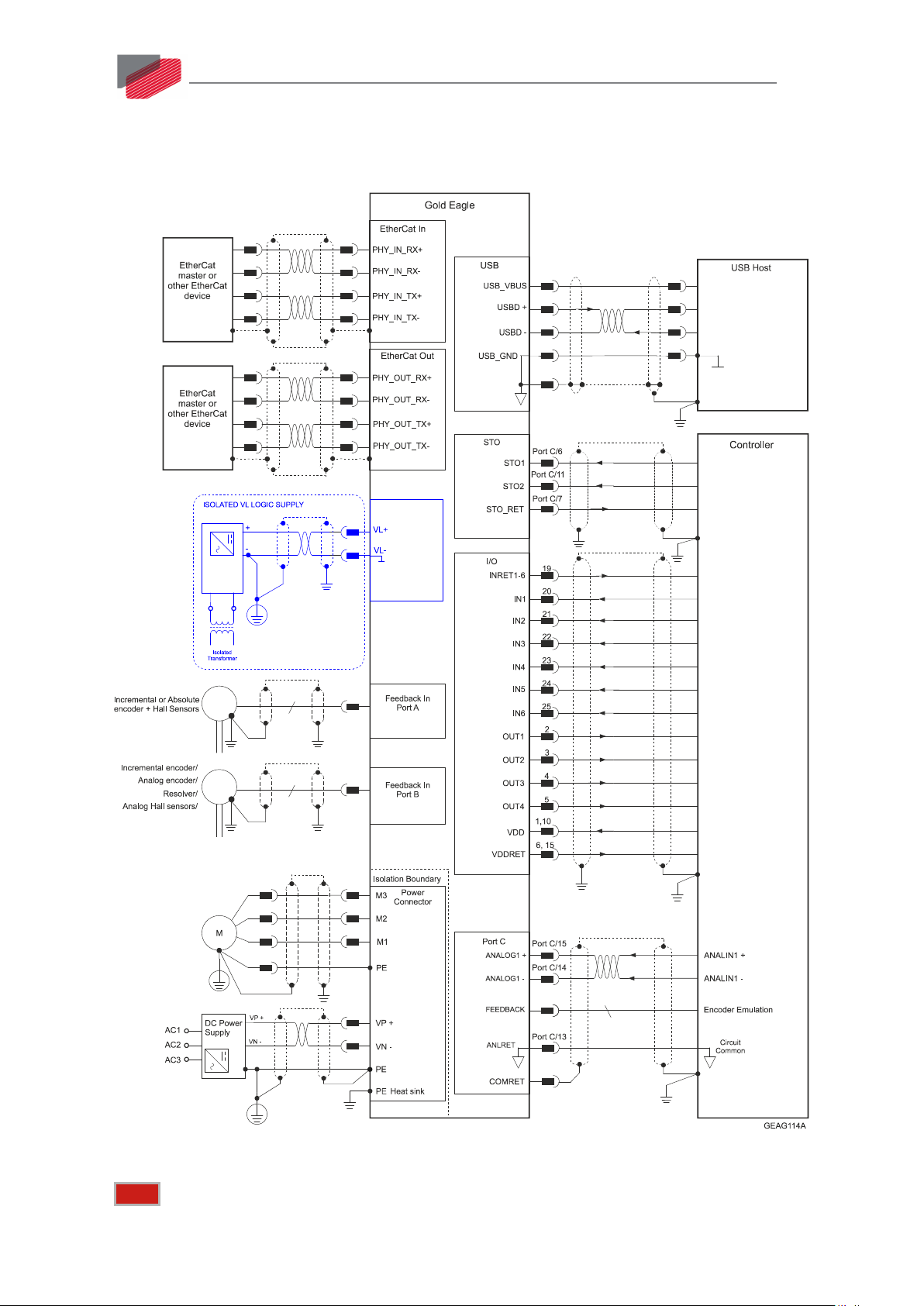
Figure 2: Gold Eagle Connection Diagram - EtherCAT
Note: The drive requires an external VL Logic power supply; the drive cannot operate without it.
||Connector Types|www.elmomc.com
Page 16
Gold Eagle Installation Guide
Table of Contents
MAN-G-EAGIG-EC (Ver. 1.000)
16
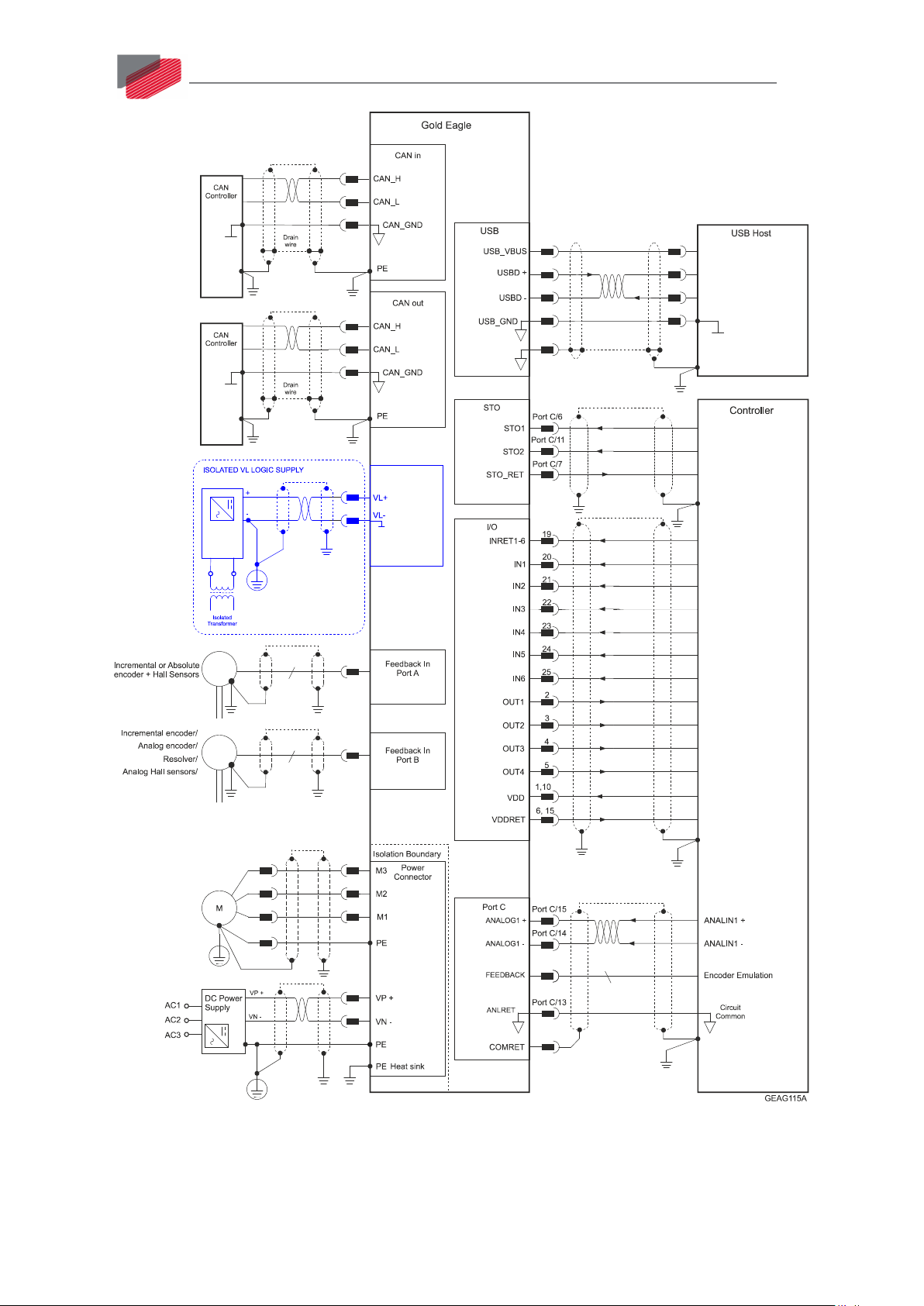
Figure 3: Gold Eagle Connection Diagram - CAN
||Connector Types|www.elmomc.com
Page 17
Gold Eagle Installation Guide
Table of Contents
Chapter 9: Wiring
MAN-G-EAGIG-EC (Ver. 1.000)
9.1. Introduction
Once the product is mounted, you are ready to wire the device. Proper wiring, grounding and
shielding are essential for ensuring safe, immune and optimal servo performance of the drive.
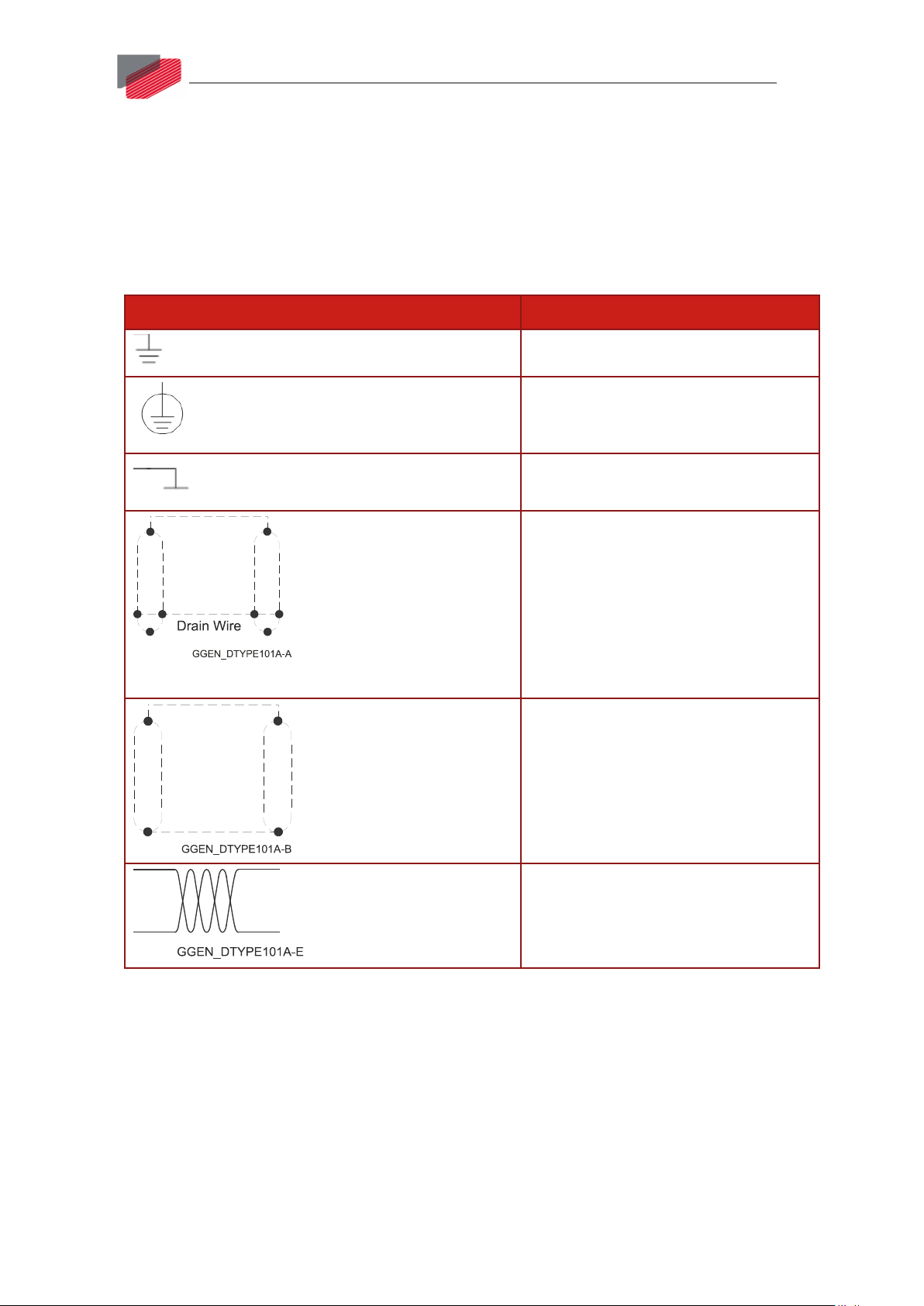
The following table legend describes the wiring symbols detailed in all installation guides.
Wiring Symbol Description
Earth connection (PE)
Protective Earth Connection
Common at the Controller
17
Shielded cable with drain wire.
The drain wire is a non-insulated wire
that is in direct contact with the braid
(shielding).
Shielded cable with drain wire
significantly simplifies the wiring and
earthing.
Shielded cable braid only, without drain
wire.
Twisted-pair wires
||Introduction|www.elmomc.com
Page 18
Gold Eagle Installation Guide
Table of Contents
MAN-G-EAGIG-EC (Ver. 1.000)
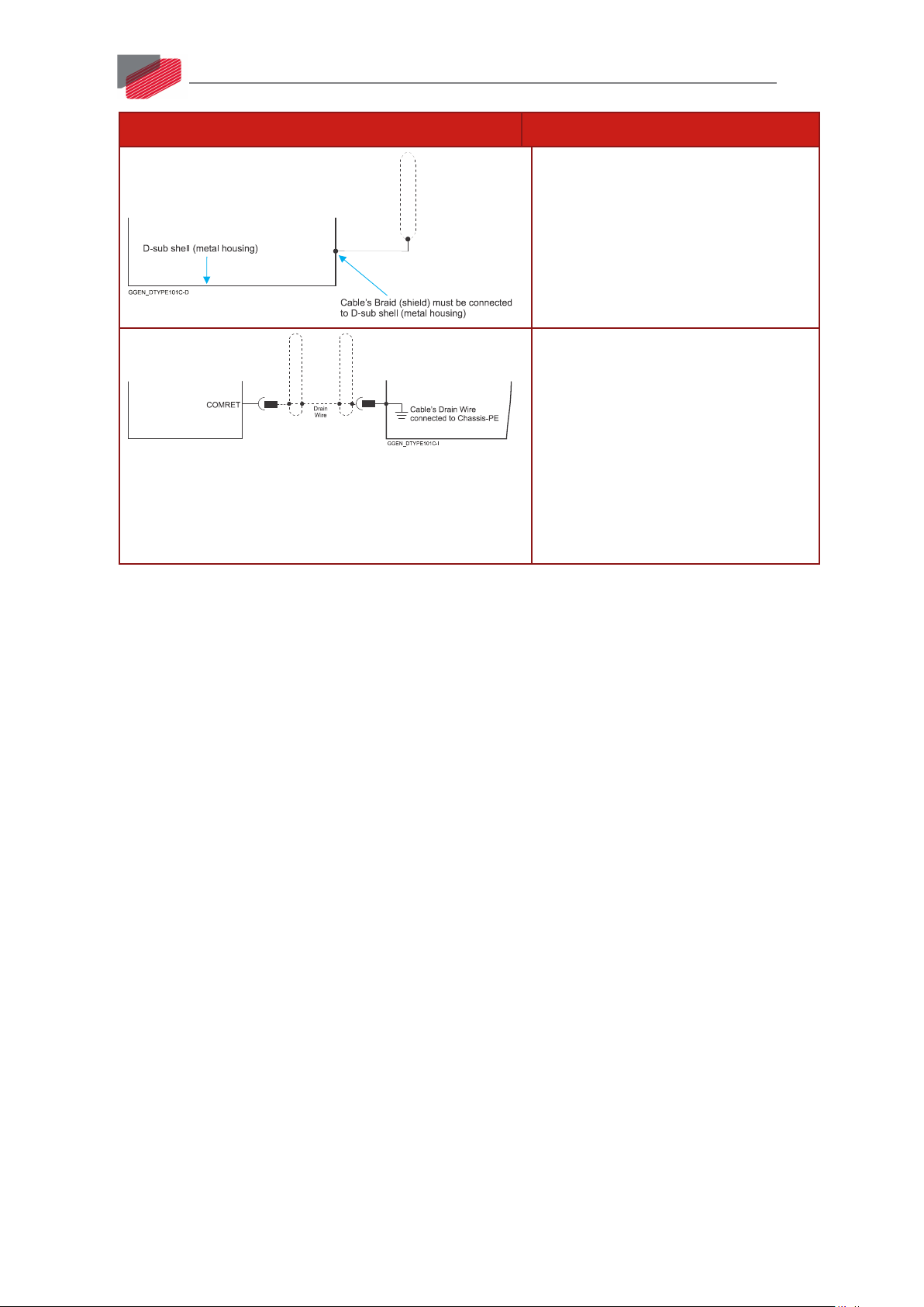
Wiring Symbol Description
D-type Connector: The cable`s braid
(Shield) must be connected to the Dsub shell (metal housing)
Encoder Earthing.
The cable`s shield is connected to the
chassis (PE) in the connector.
Earthing the Encoder and connecting
the Earth (PE) to the drive COMRET is
mandatory to insure reliable
operation, high noise immunity and
rejection of voltage common mode
interferences.
18
||Introduction|www.elmomc.com
Page 19
Gold Eagle Installation Guide
Table of Contents
MAN-G-EAGIG-EC (Ver. 1.000)
19
9.2. Basic Recommendations
9.2.1. General
1. Use shielded cables. For best results, the cable should have an aluminum foil shield covered
by copper braid, and should contain a drain wire.
Use 24, 26 or 28 AWG twisted-pair shielded with drain wire cables.
2. Keep the cable as short as possible.
Do not mount the power cables of the motor and power bus in the proximity of the control
and feedback cables.
3. Ensure that in normal operating conditions, the “earth connection” wires and shield of the
control cables carry no current. The only time these conductors carry current is under
abnormal conditions, when electrical equipment has become a potential shock or fire
hazard while conducting external EMI interferences directly to ground, in order to prevent
them from affecting the drive. Failing to meet this requirement might result in
drive/controller/host failure.
4. After completing the wiring, carefully inspect all wires to ensure tightness, good solder of
joints and general safety.
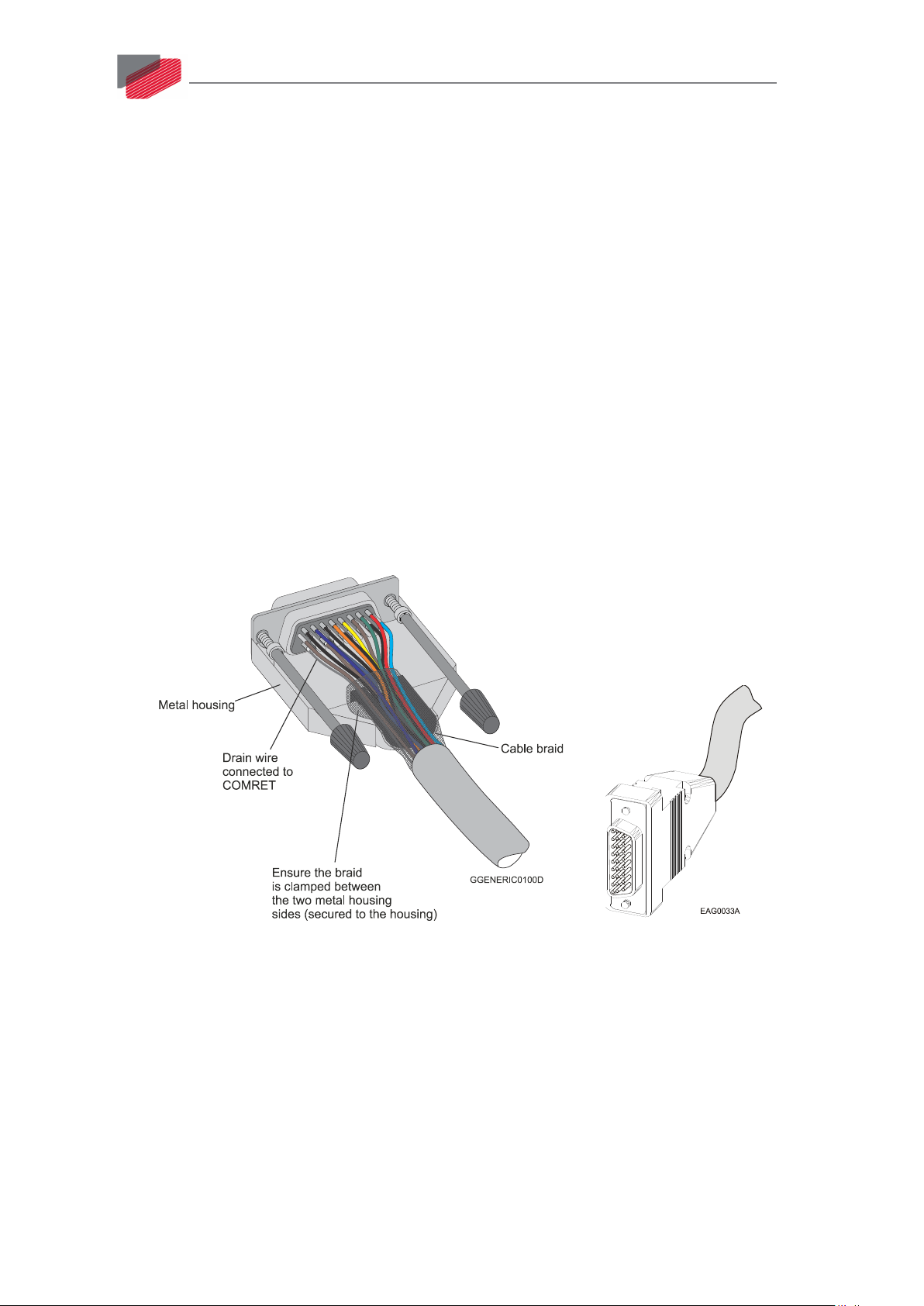
Figure 4: D-Type Cable Assemblies
5. Use only a D-Sub connector with a metal housing (Figure 4).
6. Make sure the braid shield is in tight contact with the metal housing of the D-type
connector (Figure 4).
||Basic Recommendations|www.elmomc.com
Page 20
Gold Eagle Installation Guide
Table of Contents
MAN-G-EAGIG-EC (Ver. 1.000)
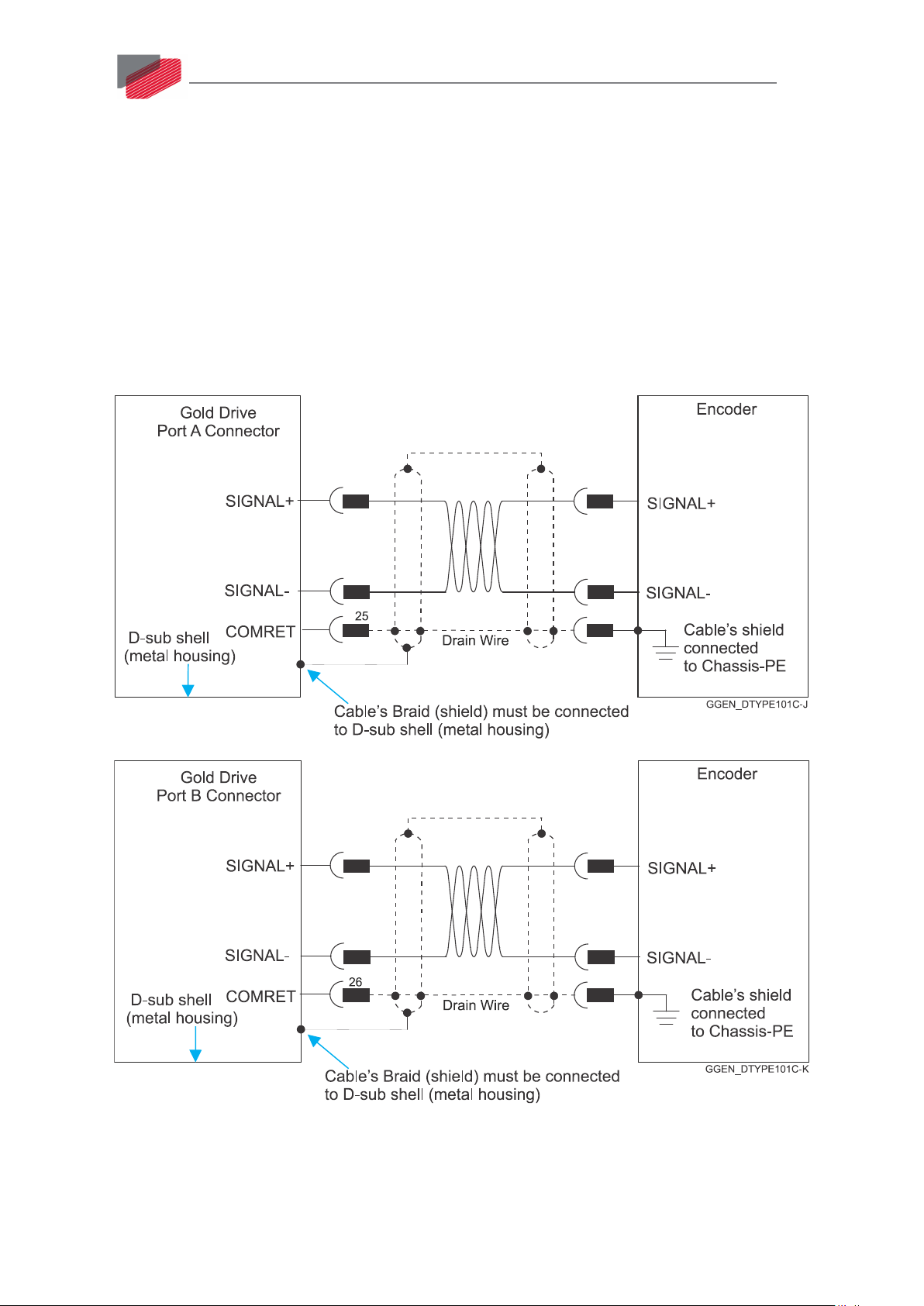
9.2.2. Feedback Cable Port A and Port B Connector
1. On the motor side connections, ground the shield to the motor chassis.
2. At least One COMRET (Common Return) must be connected to the PE.
Implement the following steps to connect the COMRET to the PE:
a. At the drive, connect the feedback drain wire to one of the COMRET terminals in the
D-Type feedback connector (Figure 5).
b. At the motor, connect the feedback cable drain wire to the GND motor chassis
terminal of the feedback connector.
The drawings below display two earth connections.
20
Figure 5: Feedback Port A and B Cable Assemblies
||Basic Recommendations|www.elmomc.com
Page 21
Gold Eagle Installation Guide
Table of Contents
MAN-G-EAGIG-EC (Ver. 1.000)
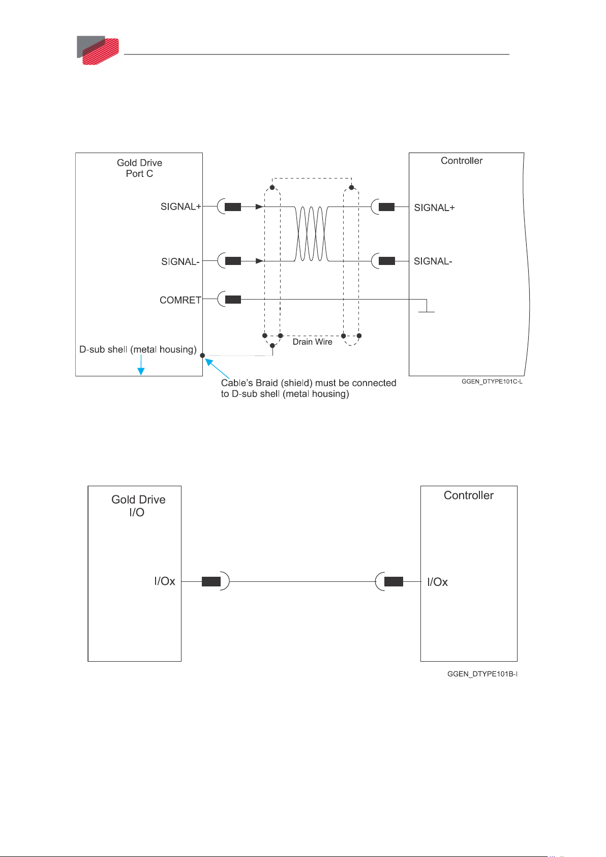
9.2.3. Feedback Cable Port C Connector
1. At the controller side connections, follow the controller manufacturer’s recommendations
concerning the shield.
2. The connection of the Drain wire to the Port C is not mandatory.
21
Figure 6: Feedback Port C Cable Assemblies
9.2.4. IO Cable Connector
It is recommended to use shielded cable, but is not mandatory.
Figure 7: Feedback IO Cable Assemblies
||Basic Recommendations|www.elmomc.com
Page 22

Gold Eagle Installation Guide
Table of Contents
MAN-G-EAGIG-EC (Ver. 1.000)
9.2.5. STO (Port C) Cable Connector
It is recommended to use shielded cable, but is not mandatory.
Figure 8: STO Cable Assemblies
22
||Basic Recommendations|www.elmomc.com
Page 23

Gold Eagle Installation Guide
Table of Contents
Pin
Function
Cable
MAN-G-EAGIG-EC (Ver. 1.000)
9.3. Motor Power Connector Pinouts
The Gold Eagle receives power from main and VL Logic supplies and delivers power to the motor.
See Chapter 8 in the in the MAN-G-Panel Mounted Drives Hardware manual for full details.
Brushless Motor Brushed DC Motor
M3 Motor phase Motor Motor
M2 Motor phase Motor Motor
M1 Motor phase Motor N/C
PE Protective Earth Motor Motor
23
||Motor Power Connector Pinouts|www.elmomc.com
Page 24

Gold Eagle Installation Guide
Table of Contents
MAN-G-EAGIG-EC (Ver. 1.000)
Figure 9: Brushless Motor Power Connection Diagram
24
Figure 10: DC Brushed Motor Power Connection Diagram
||Motor Power Connector Pinouts|www.elmomc.com
Page 25

Gold Eagle Installation Guide
Table of Contents
MAN-G-EAGIG-EC (Ver. 1.000)
9.4. Main Power Input and Motor Connections
See Chapter 8 in the in the MAN-G-Panel Mounted Drives Hardware manual for full details.
Pin Function Cable
PE Protective Earth DC Power
VN- DC Negative Power input DC Power
VP+ DC Positive Power input DC Power
25
||Main Power Input and Motor Connections|www.elmomc.com
Page 26

Gold Eagle Installation Guide
Table of Contents
MAN-G-EAGIG-EC (Ver. 1.000)
26
9.5. Connecting the DC Power and the Motor Power Cables
This section describes the installation of the cable terminal lugs for both the Main Power Cables to
VP+, VN-, and PE terminals on the Gold Eagle, and the Motor Power cables to the M1, M2, M3, and
PE terminals on the Gold Eagle.
Cable Connections
Table 2: Connecting the PE Cables
1. Connect the appropriate terminal lugs from the DC Power Input cables to the VP+, VN-, and
PE terminals on the Gold Eagle as shown in Table 2.
2. Connect the appropriate terminal lugs from the Motor Power cables to the M1, M2, M3, and
PE terminals on the Gold Eagle.
a. Install the motor cable to the drive using a barrel connector, M6 spring washer, and
secure with anM6 nut (to the drive). The required M6 nut torque is 3 Nm.
b. Install the PE wire to the drive, using a barrel connector, M5 flat washer, M5 spring
washer, and secure with an M5 screw to the heat-sink. The required M5 screw torque
is 3 Nm.
The phase connection could be arbitrary as Elmo Application Studio (EASII) will establish the proper
commutation automatically during setup. When tuning a number of drives, you can copy the setup
file to the other drives and thus avoid tuning each drive separately. In this case the motor-phase
order must be the same as on the first drive.
||Connecting the DC Power and the Motor Power Cables|www.elmomc.com
Page 27

Gold Eagle Installation Guide
Table of Contents
MAN-G-EAGIG-EC (Ver. 1.000)
27
The DC power for the Gold Drum is delivered from a separated rectifying unit (supplied by the user).
Elmo recommends using one of Elmo’s Tambourine rectifiers specifically designed for use with Elmo
servo drives which offers a range of versatile options.
9.6. Main Power
The power stage of the Gold Drum is fully isolated from the other sections of the Gold Drum, such
as the control-stage and the heat sink. This allows powering of the Gold Drum in two ways:
1. Direct to mains power supply connection. The Gold Drum is powered by a power source
that is not isolated from the mains.
2. Isolated from the mains Power supply connection. The Power supply of the Gold Drum is
isolated from the mains by an isolation transformer, or the power source is a battery
isolated from the mains.
The Gold Drum series is offered with six different operating voltage ranges. This allows optimum
servo performance and superior efficiency at any voltage. When rectifying an AC voltage source, the
AC voltage level must be limited to the "voltage supply" rating shown in Table 1, section 4.2.
9.6.1. Power Supply Connections
This section relates to the configuration of the power supply and drive, which is the DC power
source for the Gold Drum.
Connection:
1. For best EMI emission and immunity, it is highly recommended to use twisted and shielded
cable for the DC power supply cable. The gauge is determined by the actual current
consumption of the motor.
2. The Motor’s cable must not be twisted! Twisted wires create capacitance between the wires
and thus increase the EMI.
In very long Motor twisted cables ( >50m) this Capacitance might activate the short circuit
protection.
3. Connect the Power wires and cables as recommended in the connection diagrams.
||Main Power|www.elmomc.com
Page 28

Gold Eagle Installation Guide
Table of Contents
MAN-G-EAGIG-EC (Ver. 1.000)
9.6.1.1. Gold Drum Power Supply Connections
Figure 11: Non-Isolated from the Mains DC Power Supply connection
28
Figure 12: Isolated from the Mains DC Power Supply connection
Important Notice
• In the Isolated connection the G-DRU VN- terminal MUST be connected to the "Earth
Connection" (marked in red in Figure 12 above).
• In the Non Isolated Connection ( direct to Mains) the VN- terminal MUST NOT be connected to
"Earth Connection"(PE) (Figure 11).
9.6.1.2. Multiple Connections Topology
In a multi-axis application it is likely that a single power supply can feed several drives in parallel.
The power supply is connected directly to the mains AC line and it feeds more than one drive.
This topology is efficient and cost saving, by reducing the number of power supplies and the
amount of wiring. Most importantly it utilizes an energy sharing environment among all the drives
that share the same DC bus network.
||Main Power|www.elmomc.com
Page 29

Gold Eagle Installation Guide
Table of Contents
Pins
Signal
Function
Cable
MAN-G-EAGIG-EC (Ver. 1.000)
9.7. VL Logic Supply(P2)
Connect the VL Logic power supply as described below.
To connect the VL Logic supply:
1. Use a 24 – 26 AWG twisted pair shielded cable. The shield should have braid and Drain wire.
2. The source of the VL supply must be isolated from the Mains.
3. Before applying power, first verify that the polarity of the connection is correct.
29
Figure 13: VL Logic Supply Connection Diagram
9.7.1. VL Logic Supply(P2)
7, 8
9, 18
VL+ Positive input terminal of the logic (Control
& Encoders) power supply
VL- Negative (-) terminal of logic power supply VL Logic Supply Cable
Table 3: VL Logic Supply Pins and Polarity
VL Logic Supply Cable
||VL Logic Supply(P2)|www.elmomc.com
Page 30

Gold Eagle Installation Guide
Table of Contents
MAN-G-EAGIG-EC (Ver. 1.000)
9.8. Drive Status Indicator
30
Drive Status LED – CAN
Drive Status LED – EtherCAT
Figure 14: Drive Status LEDs
This red/green dual LED is used for immediate indication of the following states:
• Initiation state: In this state the LED indicates whether the drive is in the boot state (blinking
red) or in the operational state (steady red).
• Working state: In this state the LED indicates whether the drive is in an amplifier failure state
(red) or is ready to enable the motor (green).
||Drive Status Indicator|www.elmomc.com
Page 31

Gold Eagle Installation Guide
Table of Contents
Not Connected
Not Connected
Not Connected
mA Max.
MAN-G-EAGIG-EC (Ver. 1.000)
31
9.9. Port A and Port B (P1)
The Gold Eagle Port A and Port B connector is a D-Type connector with 26 high density female pins.
See Section 10.3 and 10.4 in the manual: MAN-G-Panel Mounted Drives Hardware for full details.
Common Pins and their Signals
Pin (P1) Signal Function Signal Function
1,6,10,15 +5V Encoder +5V supply +5V Encoder +5V supply
5, 14, 25, 26 COMRET Common Return COMRET Common Return
24 Not Connected
Port A Incremental Encoder Absolute Serial Encoder
Pin on
Signal Function Signal Function
P1
11 PortA_ENC_A+ Channel A+ ABS_CLK+ Abs encoder clock +
2 PortA_ENC_A- Channel A- ABS_CLK- Abs encoder clock -
12 PortA_ENC_B+ Channel B+ ABS_DATA+ Abs encoder data +
3 PortA_ENC_B- Channel B- ABS_DATA- Abs encoder data -
13 PortA_ENC_INDEX+ Index+ Reserved Reserved
4 PortA_ENC_INDEX- Index- Reserved Reserved
19 HA Hall sensor A HA Hall sensor A
20 HB Hall sensor B HB Hall sensor B
21 HC Hall sensor C HC Hall sensor C
Port B
Incremental or
Resolver
Interpolated Analog Encoder
Pin on
Signal Function Signal Function
P1
16 PortB_ENC_A+/SIN+ Channel A+ / Sine+ SIN+ Sine+
7 PortB_ENC_A-/SIN- Channel A- / Sine- SIN- Sine-
17 PortB_ENC_B+/COS+ Channel B+ /
COS+ Cosine+
Cosine+
8 PortB_ENC_B-/COS- Channel B- / Cosine- COS- Cosine-
18 PortB_ENC_INDEX+ Index+ RESOLVER_OUT+ Vref f=1/TS, 50 mA
Max.
9 PortB_ENC_INDEX- Index - RESOLVER_OUT- Vref complement
f= 1/TS, 50
||Port A and Port B (P1)|www.elmomc.com
Page 32

Gold Eagle Installation Guide
Table of Contents
MAN-G-EAGIG-EC (Ver. 1.000)
P1 Pin Position
32
26-Pin D-Type High Density Female Connector
(Elmo P.N. JCB-111026FG)
Table 4: Port A and B Pin Assignments
||Port A and Port B (P1)|www.elmomc.com
Page 33

Gold Eagle Installation Guide
Table of Contents
MAN-G-EAGIG-EC (Ver. 1.000)
9.9.1. Incremental Encoder(P1)
The following figure describes the connections at Port A for the Incremental encoder.
33
Figure 15: Port A D-Type Incremental Encoder Input – Recommended Connection Diagram
9.9.2. Hall Sensor(P1)
The following figure describes the connections at Port A for the Hall Sensor.
Figure 16: Hall Sensor Connection Diagram
||Port A and Port B (P1)|www.elmomc.com
Page 34

Gold Eagle Installation Guide
Table of Contents
MAN-G-EAGIG-EC (Ver. 1.000)
9.9.3. Absolute Serial Type Encoder(P1)
The following figures describe the connections at Port A for the Absolute Serial type encoders.
34
Figure 17: Absolute Serial Encoder – Recommended D-Type Connection Diagram for EnDAT,
Biss, and SSI
Figure 18: Absolute Serial Encoder – Recommended D-Type Connection Diagram for Sensors
Supporting Data Line Only (NRZ types, e.g., Panasonic / Mitutoyo / Sanyo Danki / Tamagawa)
||Port A and Port B (P1)|www.elmomc.com
Page 35

Gold Eagle Installation Guide
Table of Contents
MAN-G-EAGIG-EC (Ver. 1.000)
35
Figure 19: Absolute Serial Encoder – Recommended D-Type Connection Diagram for Stegmann
Hiperface
Note: When the Hiperface protocol is used, the RS-232 connection is not available.
||Port A and Port B (P1)|www.elmomc.com
Page 36

Gold Eagle Installation Guide
Table of Contents
MAN-G-EAGIG-EC (Ver. 1.000)
9.9.4. Interpolated Analog Encoder(P1)
The following figure describes the connections at Port B for the Interpolated Analog encoder.
36
Figure 20: Port B - Interpolated Analog Encoder D-Type Connection Diagram
||Port A and Port B (P1)|www.elmomc.com
Page 37

Gold Eagle Installation Guide
Table of Contents
MAN-G-EAGIG-EC (Ver. 1.000)
9.9.5. Resolver(P1)
The following figure describes the connections at Port B for the Resolver encoder.
37
Figure 21: Port B – Resolver D-Type Connection Diagram
||Port A and Port B (P1)|www.elmomc.com
Page 38

Gold Eagle Installation Guide
Table of Contents
Pin on Port C
P3
Signal
Function
MAN-G-EAGIG-EC (Ver. 1.000)
9.10. Port C Connector - Port C, Analog, and STO (P3)
The Gold Drum Port C connector is a D-Type connector with 15 high density female pins.
The Port C connector includes the following functions:
• Port C: Refer to Sections 10.5 in the in the MAN-G-Panel Mounted Drives Hardware manual
for full details
• STO: See Chapter 9 in the in the MAN-G-Panel Mounted Drives Hardware manual for full
details.
• Analog input: See Section 11.2 in the in the MAN-G-Panel Mounted Drives Hardware manual
for full details.
1 PortC_ENCO_A+ Buffered Channel A+ output/Pulse+/PWM+
2 PortC_ENCO_A- Buffered Channel A- output / Pulse- / PWM-
38
3 PortC_ENCO_B+ Buffered Channel B+ output / Dir+
4 PortC_ENCO_B- Buffered Channel B- output / Dir-
5 PortC_ENCO_Index+ Buffered Channel INDEX+ output
6 STO1 STO 1 input (default 24 V)
7 STO_RET STO signal return
8 None Not Connected
9 COMRET Common Return
10 PortC_ENCO_Index- Buffered Channel INDEX- output
11 STO2 STO 2 input (default 24 V)
12 STO_RET STO Signal Return
13 ANLRET Analog ground
14 ANALOG1- Analog input 1-
15 ANALOG1+ Analog input 1+
||Port C Connector - Port C, Analog, and STO (P3)|www.elmomc.com
Page 39

Gold Eagle Installation Guide
Table of Contents
MAN-G-EAGIG-EC (Ver. 1.000)
Pin Position
39
15-Pin D-Type High Density Female Connector
(Elmo P.N. JCB-116315FC)
Table 5: Port C Pin Assignments
||Port C Connector - Port C, Analog, and STO (P3)|www.elmomc.com
Page 40

Gold Eagle Installation Guide
Table of Contents
MAN-G-EAGIG-EC (Ver. 1.000)
9.10.1. Port C(P3)
The following figure describes the connections at Port C for the Emulated Encoder Differential.
40
Figure 22: Emulated Encoder Differential Output – Recommended D-Type Connection Diagram
9.10.2. Analog Input(P3)
The following circuit describes the internal interface of the Analog input.
Figure 23: Differential Analog D-Type Input
||Port C Connector - Port C, Analog, and STO (P3)|www.elmomc.com
Page 41

Gold Eagle Installation Guide
Table of Contents
MAN-G-EAGIG-EC (Ver. 1.000)
9.10.3. STO(P3)
The following circuits describe the STO wiring options.
9.10.3.1. Source Mode PLC Voltage Level Input
41
Figure 24: STO D-Type Input Connection – PLC Source Option
9.10.3.2. TTL Mode TTL Voltage Level Input
Figure 25: STO Input Connection – TTL Option
||Port C Connector - Port C, Analog, and STO (P3)|www.elmomc.com
Page 42

Gold Eagle Installation Guide
Table of Contents
MAN-G-EAGIG-EC (Ver. 1.000)
42
9.10.3.3. SINK Mode – PLC Voltage Level Input
Refer to the diagrams below for the PLC Sink option connections which is not fully certified for STO.
This option is not recommended for new designs.
Figure 26: STO D-Type Input Connection – Sink Option
||Port C Connector - Port C, Analog, and STO (P3)|www.elmomc.com
Page 43

Gold Eagle Installation Guide
Table of Contents
MAN-G-EAGIG-EC (Ver. 1.000)
43
9.10.3.4. STO Output(P2)
There are two available options:
• I/O and STO type without STO
• I/O and STO type with STO
If the STO STATUS OUT is configured, then OUT 4 will not be available. Refer to Figure 27 below for
details of the connections. Refer to Chapter 9 in the in the MAN-G-Panel Mounted Drives Hardware
manual for full details.
Figure 27: STO Output
||Port C Connector - Port C, Analog, and STO (P3)|www.elmomc.com
Page 44

Gold Eagle Installation Guide
Table of Contents
MAN-G-EAGIG-EC (Ver. 1.000)
9.11. Digital Inputs and Outputs (P2)
The Gold Drum Port C connector is a D-Type connector with 26 high density male pins. Refer to
Chapter 11 in the in the MAN-G-Panel Mounted Drives Hardware manual for full details.
The following table lists the digital input pin assignments.
I/O Pins(P2) Signal Function
1, 10 VDD Supply for out 1-4
2 OUT1 Programmable output 1
3 OUT2 Programmable output 2
4 OUT3 Programmable output 3
5 OUT4 Programmable output 4
STO_OUT_E STO Emitter output option
(see Catalog/Part Number options)
44
6, 15 VDDRET Supply return for out 1-4
7, 8 VL+ +24 Volts Supply Input Positive
9, 18 VL- 24 Volts RET Supply Input Return
11, 12, 13, 16, 17,
None Not Connected
26
14 STO_OUT_C STO Collector output option (see Catalog/Part Number options)
19 INRET1-6 Programmable inputs 1 to 6 return for the standard version
Programmable positive input 1 to 6 for the Sink version
20 IN1 High Speed, programmable input 1 (event capture, home, general
purpose, RLS, FLS, INH, PWM & direction input, pulse & direction
input)
21 IN2 High Speed, programmable input 2 (event capture, home, general
purpose, RLS, FLS, INH, PWM & direction input, pulse & direction
input)
22 IN3 High Speed, programmable input 3 (event capture, home, general
purpose, RLS, FLS, INH, PWM & direction input, pulse & direction
input)
23 IN4 High Speed, programmable input 4 (event capture, home, general
purpose, RLS, FLS, INH, PWM & direction input, pulse & direction
input)
24 IN5 High Speed, programmable input 5 (event capture, home, general
purpose, RLS, FLS, INH, PWM & direction input, pulse & direction
input)
25 IN6 High Speed, programmable input 6 (event capture, home, general
||Digital Inputs and Outputs (P2)|www.elmomc.com
Page 45

Gold Eagle Installation Guide
Table of Contents
purpose, RLS, FLS, INH, PWM & direction input, pulse & direction
MAN-G-EAGIG-EC (Ver. 1.000)
Pin Position
45
input)
26-Pin D-Type Male Connector
(Elmo P.N. JCB-205026M0)
Table 6: I/O Pin Assignments
||Digital Inputs and Outputs (P2)|www.elmomc.com
Page 46

Gold Eagle Installation Guide
Table of Contents
MAN-G-EAGIG-EC (Ver. 1.000)
9.11.1. Digital Input and Output TTL Mode(P2)
The following figure describes the connections at the I/O Port for the Digital Input and Output TTL
Mode.
46
Figure 28: Digital Input TTL Mode D-Type Connection Diagram
||Digital Inputs and Outputs (P2)|www.elmomc.com
Page 47

Gold Eagle Installation Guide
Table of Contents
MAN-G-EAGIG-EC (Ver. 1.000)
47
Figure 29: Digital Output D-Type Connection Diagram – TTL Option
||Digital Inputs and Outputs (P2)|www.elmomc.com
Page 48

Gold Eagle Installation Guide
Table of Contents
MAN-G-EAGIG-EC (Ver. 1.000)
9.11.2. Digital Input and Output PLC Source Mode(P2)
The following figure describes the connections at the I/O Port for the Digital Input and Output PLC
Mode.
48
Figure 30: Digital Input D-Type Connection Diagram – Source PLC Option
||Digital Inputs and Outputs (P2)|www.elmomc.com
Page 49

Gold Eagle Installation Guide
Table of Contents
MAN-G-EAGIG-EC (Ver. 1.000)
49
Figure 31: Digital Output D-Type Connection Diagram – Source PLC Option
||Digital Inputs and Outputs (P2)|www.elmomc.com
Page 50

Gold Eagle Installation Guide
Table of Contents
MAN-G-EAGIG-EC (Ver. 1.000)
9.11.3. Digital Input and Output Sink Mode(P2)
The following figure describes the connections at the I/O Port for the Digital Input and Output Sink
Mode.
50
Figure 32: Digital Input Sink Mode – PLC voltage level D-Type Connection Diagram
||Digital Inputs and Outputs (P2)|www.elmomc.com
Page 51

Gold Eagle Installation Guide
Table of Contents
MAN-G-EAGIG-EC (Ver. 1.000)
51
Figure 33: Digital Output as Sink Configuration D-Type Connection Diagram
||Digital Inputs and Outputs (P2)|www.elmomc.com
Page 52

Gold Eagle Installation Guide
Table of Contents
MAN-G-EAGIG-EC (Ver. 1.000)
9.12. Communications (P4)
The Gold Eagle Communication connector is a D-Type connector with 15 high density male pins.
The Communication connector includes the following functions:
• EtherCAT communication connectors: See Section 12.2 MAN-G-Panel Mounted Drives
Hardware manual for full details.
• CAN communication connectors: See Section 12.4 MAN-G-Panel Mounted Drives Hardware
manual for full details.
• USB: See Section 12.1 in the MAN-G-Panel Mounted Drives Hardware manual for full details.
• RS-232: See Section 12.5 MAN-G-Panel Mounted Drives Hardware manual for full details.
EtherCAT Network Communication Version (Part Number E or F)
Pin on P4 Signal Function
1 USB VBUS USB VBUS 5V
52
2 USBD+ USB _P line
3 USBD- USB _N line
4 COMRET Common Return
5 USB_SHIELD
6 RS232_TX RS-232 Transmit
7 ECAT_IN_TX+ EtherCAT In Transmit
8 ECAT_IN_RX+ EtherCAT In Receive +
9 ECAT_OUT_TX+ EtherCAT Out Transmit+
10 ECAT_OUT_RX+ EtherCAT Out Receive+
11 RS232_RX RS-232 Receive
12 ECAT_IN_TX- EtherCAT In Transmit
13 ECAT_IN_RX- EtherCAT In Receive -
14 ECAT_OUT_TX- EtherCAT Out Transmit-
15 ECAT_OUT_RX- EtherCAT Out Receive-
||Communications (P4)|www.elmomc.com
Page 53

Gold Eagle Installation Guide
Table of Contents
MAN-G-EAGIG-EC (Ver. 1.000)
CAN Network Communication Version (Part Number S or T)
Pin on P4 Signal Function
1 USB VBUS USB VBUS 5V
2 USBD+ USB _P line
3 USBD- USB _N line
4 COMRET Common Return
5 USB_SHIELD
6 RS232_TX- /RS422_TX- RS-232 Transmit/RS422 Transmit-(Differential RS-232)
7 RS422_RX+ RS422 Receive+(Differential RS-232)
8 Not in use Not in use
9 CANH CAN_H bus line (dominant high)
10 CANH CAN_H bus line (dominant high)
53
11 RS232_RX- /RS422_TX+ RS-232 Receive/ RS422 Transmit+(Differential RS-232)
12 RS422_RX- RS-422 RX-(Differential RS-232)
13 Not in use Not in use
14 CANL CAN_L bus line (dominant low)
15 CANL CAN_L bus line (dominant low)
||Communications (P4)|www.elmomc.com
Page 54

Gold Eagle Installation Guide
Table of Contents
Pin Position
MAN-G-EAGIG-EC (Ver. 1.000)
54
15-Pin D-Type High Density Male Connector
(Elmo P.N. JCB-106315MC)
Table 7: Communication Pin Assignments
||Communications (P4)|www.elmomc.com
Page 55

Gold Eagle Installation Guide
Table of Contents
MAN-G-EAGIG-EC (Ver. 1.000)
9.12.1. USB 2.0(P4)
See Section 12.1 in the in the MAN-G-Panel Mounted Drives Hardware manual for full details.
Figure 34: USB Network Diagram
55
||Communications (P4)|www.elmomc.com
Page 56

Gold Eagle Installation Guide
Table of Contents
MAN-G-EAGIG-EC (Ver. 1.000)
9.12.2. EtherCAT Communications Version
Fieldbus communications are industrial network protocols for real-time distributed control that
allows connection of servo drives.
See Section 12.2 in the MAN-G-Panel Mounted Drives Hardware manual for the electrical diagram.
9.12.2.1. EtherCAT Wiring(P4)
Figure 35 describes the wiring diagram for the EtherCAT connections.
56
Figure 35: EtherCAT with D-Type Connections
||Communications (P4)|www.elmomc.com
Page 57

Gold Eagle Installation Guide
Table of Contents
MAN-G-EAGIG-EC (Ver. 1.000)
9.12.2.2. EtherCAT Status Indicator
Figure 36 displays the LEDs available in the EtherCAT Version
57
Figure 36: Drive Status LEDs
The EtherCAT status indicator is a red/green dual LED. It combines run indication (when it is green)
and error indication (when it is red) of the EtherCAT device.
||Communications (P4)|www.elmomc.com
Page 58

Gold Eagle Installation Guide
Table of Contents
MAN-G-EAGIG-EC (Ver. 1.000)
9.12.2.3. EtherCAT Address Switches
Figure 37 displays the switches available in the EtherCAT Version
58
Figure 37: EtherCAT Address Switches
The EtherCAT address switches sets the ECAT address (L is ADD low, H is ADD hi). Figure 37 above,
allow the user to define a unique node ID to a slave. The two rotary switches offer up to 255
addresses, with the 0 setting referring to No alias address.
The positions of the switches on the drive are shown in Figure 37. Use a screwdriver to set the low
and high bytes values of the drive EtherCAT address. This address is only retrieved after power-up.
||Communications (P4)|www.elmomc.com
Page 59

Gold Eagle Installation Guide
Table of Contents
MAN-G-EAGIG-EC (Ver. 1.000)
9.12.3. CAN Communications Version
Fieldbus communications are industrial network protocols for real-time distributed control that
allows connection of servo drives.
9.12.3.1. CAN Wiring(P4)
Figure 38 describes the CAN wiring diagram on the next page.
59
||Communications (P4)|www.elmomc.com
Page 60

Gold Eagle Installation Guide
Table of Contents
MAN-G-EAGIG-EC (Ver. 1.000)
60
Figure 38: Gold Eagle Connection Diagram – CAN
||Communications (P4)|www.elmomc.com
Caution
When installing the CAN
communications, ensure that each
servo
drive is allocated a unique ID.
Otherwise, the CAN network may
hang.
Page 61

Gold Eagle Installation Guide
Table of Contents
MAN-G-EAGIG-EC (Ver. 1.000)
9.12.4. RS-232(P4)
The following is the recommended for RS-232 cabling:
4. Connect the shield to the ground of the host (PC). Usually, this connection is soldered
internally inside the connector at the PC end. You can use the drain wire to facilitate
connection.
5. The RS-232 communication port is non-isolated.
6. Ensure that the shield of the cable is connected to the shield of the connector used for
RS-232 communications. The drain wire can be used to facilitate the connection.
61
Figure 39: RS-232 Connection Diagram Example
||Communications (P4)|www.elmomc.com
Page 62

Gold Eagle Installation Guide
Table of Contents
MAN-G-EAGIG-EC (Ver. 1.000)
9.12.5. RS-422 (Differential RS-232) Communication(P4)
62
Figure 40: RS-422 (Differential RS-232) Communication Connection Diagram
||Communications (P4)|www.elmomc.com
Page 63

Gold Eagle Installation Guide
Table of Contents
Chapter 10: Powering Up
MAN-G-EAGIG-EC (Ver. 1.000)
After the Gold Eagle is connected to its device, it is ready to be powered up.
Caution:
Before applying power, ensure that the DC supply is within the specified range
and that the proper plus-minus connections are in order.
10.1. Initializing the System
After the Gold Eagle has been connected and mounted, the system must be set up and initialized.
This is accomplished using the EASII, Elmo’s Windows-based software application. Install the
application and then perform setup and initialization according to the directions in the EASII User
Manual.
63
||Initializing the System|www.elmomc.com
Page 64

Gold Eagle Installation Guide
Table of Contents
Chapter 11: Heat Dissipation
MAN-G-EAGIG-EC (Ver. 1.000)
64
For full power output capability the Gold Eagle is designed to be mounted on an external heat-sink.
It is highly recommended that the “Wall” on which the Gold Eagle is mounted will have heat
dissipation capabilities. The Gold Eagle at “free air convection” (without an additional heat-sink) can
dissipate around 12 W for 40 °C ambient temperature and not exceeding 80 °C on the heat sink.
When “Free Air Convection” is sufficient for the application it is recommended to leave
approximately 10 mm of space between the Gold Eagle’s heat sink and any other assembly.
11.1. Gold Eagle Thermal Data
• Free air convection thermal resistance (θ): Approximately 3.6 to 4 °C/W.
• Thermal time constant: Approximately 40 minutes/ 2400 seconds (thermal time constant
means that the Gold Eagle will reach 2/3 of its final temperature after 4 minutes).
• Self-heat dissipation capability (no external heat sink): 12 W for 40 °C/W temperature rise.
• Shut-off temperature: 86 °C to 88 °C (measured on the heat sink).
• The thermal resistance when connecting to an external heat sink:
The surface of the external heat-sink is 50 μm: 0.18 °C/W.
Thermal conductive compound. By proper Smearing of the surface a significant
improvement of the thermal resistance is achieved: 0.13 °C/W
||Gold Eagle Thermal Data|www.elmomc.com
Page 65

Gold Eagle Installation Guide
Table of Contents
Power Dissipation 60V series
0
10
20
30
40
50
60
70
80
90
100
0 12 20 30 40 50 60 70 80 90
Motor's Current (Ampere)
Power Dissipation (W)
12VDC
20VDC
30VDC
40VDC
50VDC
56VDC
Standard 40 °C Ambient Temp.
Heatsink
Heat sink
EAGLE
MAN-G-EAGIG-EC (Ver. 1.000)
11.2. Heat Dissipation Data
Heat Dissipation is shown in graphically below:
65
Required
not required
||Heat Dissipation Data|www.elmomc.com
Page 66

Gold Eagle Installation Guide
Table of Contents
Power Dissipation 200V series
0
50
100
150
200
250
0 6.7 13.3 20.0 26.7 33.3 40.0 46.7 53.3 60.0
Motor's Current (Ampere)
Power Dissipation (W)
40VDC
80VDC
120VDC
160VDC
196VDC
MAN-G-EAGIG-EC (Ver. 1.000)
66
11.3. How to Use the Charts
The charts above are based upon theoretical worst-case conditions. Actual test results show 30% to
50% better power dissipation.
To determine if your application needs a heat sink:
1. Allow maximum heat sink temperature to be 80 °C or less (shunt down is 6 °C to 8 °C higher).
2. Determine the ambient operating temperature of the Drum as ≤ 40 °C.
3. Calculate the allowable temperature increase according to the following example: For an
ambient temperature of 40 °C, ΔT = 80 °C to 40 °C = 40 °C
4. Use the chart to find the actual dissipation power of the drive. Follow the voltage curve to the
desired output current and then find the dissipated power.
5. If the dissipated power is below 12W the Drum needs no additional cooling.
Note: The chart above shows that no heat sink is necessary when the heat sink temperature is
80 °C, ambient temperature is 40 °C and heat dissipated is 12 W.
||How to Use the Charts|www.elmomc.com
Page 67

Gold Eagle Installation Guide
Table of Contents
Chapter 12: Gold Eagle Dimensions
MAN-G-EAGIG-EC (Ver. 1.000)
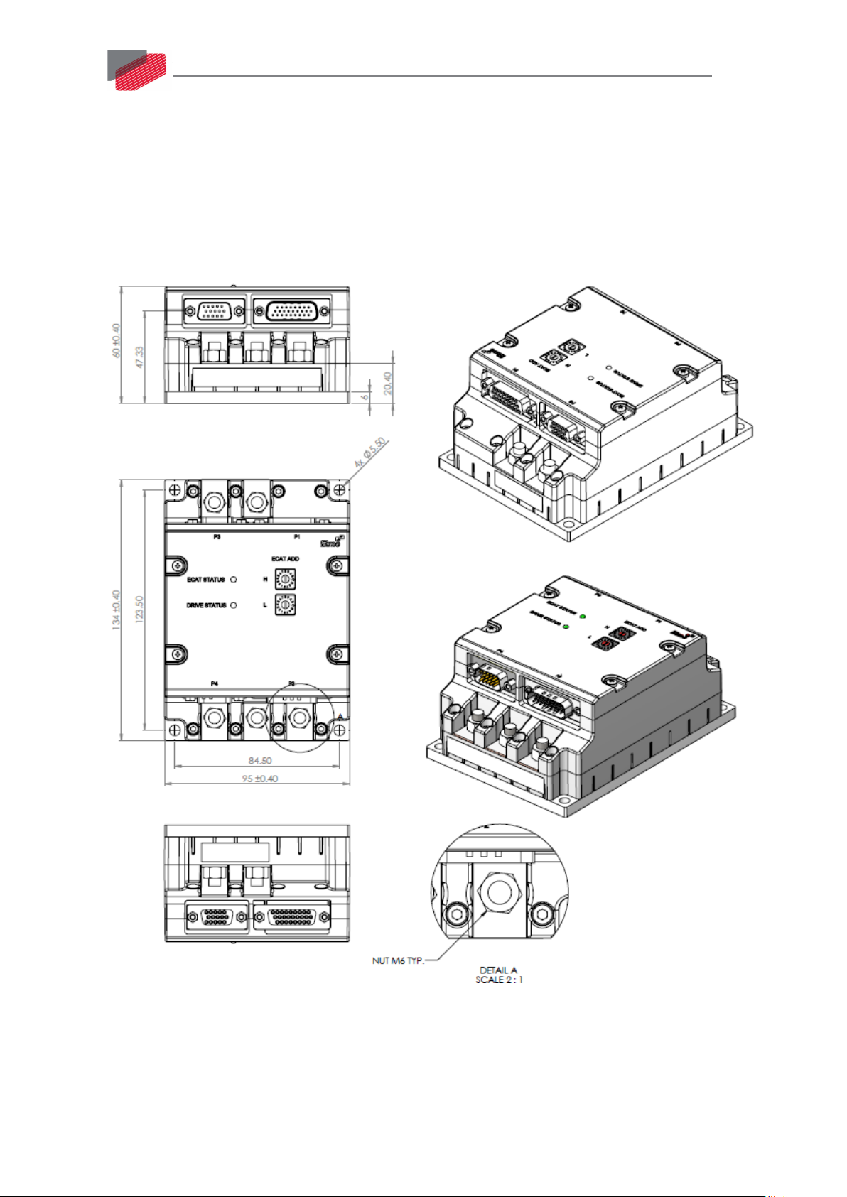
This chapter provides detailed technical information regarding the Gold Eagle.
67
Figure 41: Gold Eagle Technical Drawings
||How to Use the Charts|www.elmomc.com
Page 68

Table of Contents
68
||How to Use the Charts|www.elmomc.com
 Loading...