

Page 1
Gold DC Trombone
Digital Servo Drive
Installation Guide
EtherCAT and CAN
September 2014 (Ver. 1.900) www.elmomc.com
Page 2
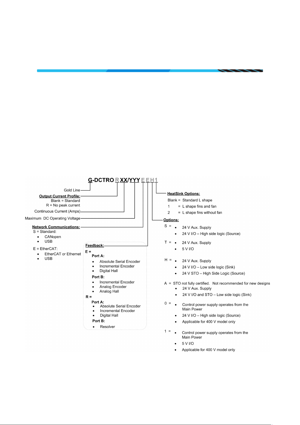
Table of Contents
Notice
This guide is delivered subject to the following conditions and restrictions:
• This guide contains proprietary information belonging to Elmo Motion Control Ltd. Such
information is supplied solely for the purpose of assisting users of the Gold DC Trombone
servo drive in its installation.
• The text and graphics included in this manual are for the purpose of illustration and reference
only. The specifications on which they are based are subject to change without notice.
• Information in this document is subject to change without notice.
Document no. MAN-G-DCTROIG-EC (Ver. 1.900)
Copyright 2014
Elmo Motion Control Ltd.
All rights reserved.
Catalog Number
|Warnings|www.elmomc.com
Page 3

Table of Contents
Version
Date
Details
Revision History
Ver. 1.900 Sep 2014 Initial release in new format
|Warnings|www.elmomc.com
Page 4

Table of Contents
Table of Contents
MAN-G-DCTRO IG-EC (Ver. 1.900)
Chapter 1: This Installation Guide ................................................................................. 6
Chapter 2: Safety Information ...................................................................................... 6
2.1 Warnings .................................................................................................................... 7
2.2 Cautions ...................................................................................................................... 7
2.3 CE Marking Conformance ........................................................................................... 7
2.4 Warranty Information ................................................................................................ 7
Chapter 3: Product Description ..................................................................................... 8
Chapter 4: Technical Information .................................................................................. 9
4.1 Physical Specifications ................................................................................................ 9
4.2 Technical Data for the 400 V Type ............................................................................. 9
4.3 Technical Data for the 800 V Type ........................................................................... 10
4.4 Auxiliary Supply ........................................................................................................ 11
4.5 Product Features ...................................................................................................... 11
4
Chapter 5: Installation ................................................................................................ 12
5.1 Unpacking the Drive Components ........................................................................... 12
5.2 Connector Types ....................................................................................................... 13
5.2.1 Mating Connector Types ........................................................................... 15
5.3 Mounting the Gold DC Trombone ............................................................................ 16
5.4 Connection Diagrams ............................................................................................... 17
5.4.1 Connection Diagrams for EtherCAT Version.............................................. 18
5.4.2 Connection Diagrams for CAN Version ...................................................... 20
Chapter 6: Wiring ....................................................................................................... 22
6.1 Basic Recommendations .......................................................................................... 24
6.1.1 General ...................................................................................................... 24
6.1.2 Feedback Cable Port A and Port B Connector ........................................... 25
6.1.3 Feedback Cable Port C Connector ............................................................. 26
6.1.4 IO Cable Connector .................................................................................... 26
6.1.5 STO (Port C) Cable Connector .................................................................... 27
6.2 Motor Power Connector Pinouts ............................................................................. 28
6.3 Main Power .............................................................................................................. 30
6.3.1 Direct-to-Mains Power Source (Non-Isolated Rectifier)............................ 31
6.3.2 Three-Phase Direct-to-Mains Connection Topology ................................. 32
6.3.3 Single-Phase Direct-to-Mains Connection Topology ................................. 33
6.3.4 Multiple Connections Topology................................................................. 34
6.3.5 Battery Power Supply ................................................................................ 35
6.4 Auxiliary Power ......................................................................................................... 36
6.5 Port A ........................................................................................................................ 38
6.5.1 Incremental Encoder .................................................................................
39
|Warnings|www.elmomc.com
Page 5

Table of Contents
Table of Contents
MAN-G-DCTRO IG-EC (Ver. 1.900)
6.5.2 Hall Sensor ................................................................................................. 39
6.5.3 Absolute Serial Type Encoder .................................................................... 40
6.6 Port B ........................................................................................................................ 42
6.6.1 Incremental Encoder ................................................................................. 43
6.6.2 Interpolated Analog Encoder .................................................................... 44
6.6.3 Resolver ..................................................................................................... 45
6.7 Port C, Analog Input, and STO .................................................................................. 46
6.7.1 Port C ......................................................................................................... 48
6.7.2 Analog Input .............................................................................................. 48
6.7.3 STO ............................................................................................................. 49
6.7.3.1 Source Mode PLC Voltage Level ............................................... 49
6.7.3.2 TTL Mode TTL Voltage Level ..................................................... 49
6.7.3.3 SINK Mode – PLC Voltage Level ................................................ 50
6.8 Digital Inputs and Outputs ....................................................................................... 51
6.8.1 Digital Input and Output TTL Mode ........................................................... 53
6.8.2 Digital Input and Output PLC Source Mode .............................................. 55
6.8.3 Digital Input and Output Sink Mode .......................................................... 57
6.9 USB 2.0 ..................................................................................................................... 59
6.10 Drive Status Indicator ............................................................................................... 60
6.11 EtherCAT Communications Version ......................................................................... 61
6.11.1 EtherCAT In/Ethernet Pinouts ................................................................... 61
6.11.2 EtherCAT Out Pinouts ................................................................................ 62
6.11.3 EtherCAT Wiring ........................................................................................ 62
6.11.4 EtherCAT Link Indicators ........................................................................... 63
6.11.5 EtherCAT Status Indicator ......................................................................... 63
6.12 CAN Communications Version ................................................................................. 64
6.12.1 CAN Wiring ................................................................................................ 65
5
Chapter 7: Powering Up ............................................................................................. 66
7.1 Initializing the System .............................................................................................. 66
Chapter 8: Gold DC Trombone Dimensions ................................................................. 67
|Warnings|www.elmomc.com
Page 6
Gold DC Trombone Installation Guide
Table of Contents
Chapter 1:
This Installation Guide
Chapter 2:
Safety Information
Warning:
Caution:
Important:
MAN-G-DCTROI G-EC (Ver. 1.900)
6
This installation Guide details the technical data, pinouts, wiring, and power connectivity of the
Gold DC Trombone. For a comprehensive detailed description of the functions refer to the
MAN-G-Panel Mounted Drives Hardware manual which describes Panel Mounted products.
In order to achieve the optimum, safe operation of the Gold DC Trombone, it is imperative that you
implement the safety procedures included in this installation guide. This information is provided to
protect you and to keep your work area safe when operating the Gold DC Trombone and
accompanying equipment.
Please read this chapter carefully before you begin the installation process.
Before you start, ensure that all system components are connected to earth ground. Electrical
safety is provided through a low-resistance earth connection.
Only qualified personnel may install, adjust, maintain and repair the servo drive. A qualified person
has the knowledge and authorization to perform tasks such as transporting, assembling, installing,
commissioning and operating motors.
The Gold DC Trombone contains electrostatic-sensitive components that can be damaged if handled
incorrectly. To prevent any electrostatic damage, avoid contact with highly insulating materials,
such as plastic film and synthetic fabrics. Place the product on a conductive surface and ground
yourself in order to discharge any possible static electricity build-up.
To avoid any potential hazards that may cause severe personal injury or damage to the product
during operation, keep all covers and cabinet doors shut.
The following safety symbols are used in this and all Elmo Motion Control manuals:
This information is needed to avoid a safety hazard, which might cause bodily injury
or death as a result of incorrect operation.
This information is necessary to prevent bodily injury, damage to the product or to
other equipment.
Identifies information that is critical for successful application and understanding of
the product.
|Warnings|www.elmomc.com
Page 7
Gold DC Trombone Installation Guide
Table of Contents
MAN-G-DCTROI G-EC (Ver. 1.900)
2.1 Warnings
• To avoid electric arcing and hazards to personnel and electrical contacts, never
connect/disconnect the servo drive while the power source is on.
• Power cables can carry a high voltage, even when the motor is not in motion. Disconnect
the Gold DC Trombone from all voltage sources before servicing.
• The high voltage products within the Gold Line range contain grounding conduits for electric
current protection. Any disruption to these conduits may cause the instrument to become
hot (live) and dangerous.
• After shutting off the power and removing the power source from your equipment, wait at
least 1 minute before touching or disconnecting parts of the equipment that are normally
loaded with electrical charges (such as capacitors or contacts). Measuring the electrical
contact points with a meter, before touching the equipment, is recommended.
2.2 Cautions
7
• The maximum DC power supply connected to the instrument must comply with the
parameters outlined in this guide.
• When connecting the Gold DC Trombone to an approved isolated auxiliary power supply,
connect it through a line that is separated from hazardous live voltages using reinforced or
double insulation in accordance with approved safety standards.
• Before switching on the Gold DC Trombone, verify that all safety precautions have been
observed and that the installation procedures in this manual have been followed.
• Make sure that the Safe Torque Off is operational
2.3 CE Marking Conformance
The Gold DC Trombone is intended for incorporation in a machine or end product. The actual end
product must comply with all safety aspects of the relevant requirements of the European Safety of
Machinery Directive 2006/42/EC as amended, and with those of the most recent versions of
standards EN 60204-1 and
Concerning electrical equipment designed for use within certain voltage limits, the Gold DC
Trombone meets the provisions outlined in 2006/95/EC. The party responsible for ensuring that the
equipment meets the limits required by EMC regulations is the manufacturer of the end product.
EN ISO 12100 at the least, and in accordance with 2006/95/EC.
2.4 Warranty Information
The products covered in this manual are warranted to be free of defects in material and
workmanship and conform to the specifications stated either within this document or in the
product catalog description. All Elmo drives are warranted for a period of 12 months from the time
of installation, or 18 months from time of shipment, whichever comes first. No other warranties,
expressed or implied — and including a warranty of merchantability and fitness for a particular
purpose — extend beyond this warranty.
||Warnings|www.elmomc.com
Page 8

Gold DC Trombone Installation Guide
Table of Contents
Chapter 3:
Product Description
MAN-G-DCTROI G-EC (Ver. 1.900)
8
The Gold DC Trombone series of digital servo drives are highly resilient and designed to deliver the
highest density of power and intelligence. The Gold DC Trombone delivers up to 10 kW of
continuous power or 16 kW of peak power in a compact package.
The digital drives are part of Elmo’s advanced Gold Line. They operate from a DC power source in
current, velocity, position and advanced position modes, in conjunction with a permanent-magnet
synchronous brushless motor, DC brush motor, linear motor or voice coil. They are designed for use
with any type of sinusoidal and trapezoidal commutation, with vector control. The Gold DC
Trombone can operate as a stand-alone device or as part of a multi-axis system in a distributed
configuration on a real-time network.
based application enables users to quickly and simply configure the servo drive for optimal use with
their motor. The Gold DC Trombone, as part of the Gold Line, is fully programmable with Elmo’s
motion control language.
Power to the drives is provided by a DC power source (not included with the Gold DC Trombone).
Since the power stage is fully isolated from the control stage, the DC rectifier can be fed directly
from the mains, without the need for a bulky and expensive transformer.
If backup functionality is required to store control parameters in the event of a mains power
outage, then an A, H, S, or T optional Gold DC Trombone should be used, with an external 24 VDC
isolated supply connected to it.
Note: The backup functionality can operate from an isolated voltage source within the range of
18 to 30 VDC.
Whenever backup functionality is not required, Gold DC Trombone models with the 0 or 1 Option
(only for 400 V models) in the catalog number (section Catalog Number) can be used, i.e., they do
not have a 24 V control supply. In these models, a smart control-supply algorithm enables the Gold
DC Trombone to operate with only the main power supply VP+ and VN-, with no need for a 24 VDC
auxiliary power supply for the logic.
The Gold DC Trombone is a stand-alone version of the Gold Trombone module (PCB-mounted).
Another pluggable version, the Gold Solo Trombone is also available.
||Warranty Information|www.elmomc.com
Page 9
Gold DC Trombone Installation Guide
9
Table of Contents
Chapter 4:
Technical Information
VDC
A, H, S, or T in P/N*: 50
VDC
325
VDC
400
kW 2 4 5 5.5
7
%
> 98
VDC
18 V to 30 V
VA
7
A 6 12
16
17
22
A
4.2
8.5
11.3
12
15.5
A
2 x Ic
No peak
MAN-G-DCTROI G-EC (Ver. 1.900)
9
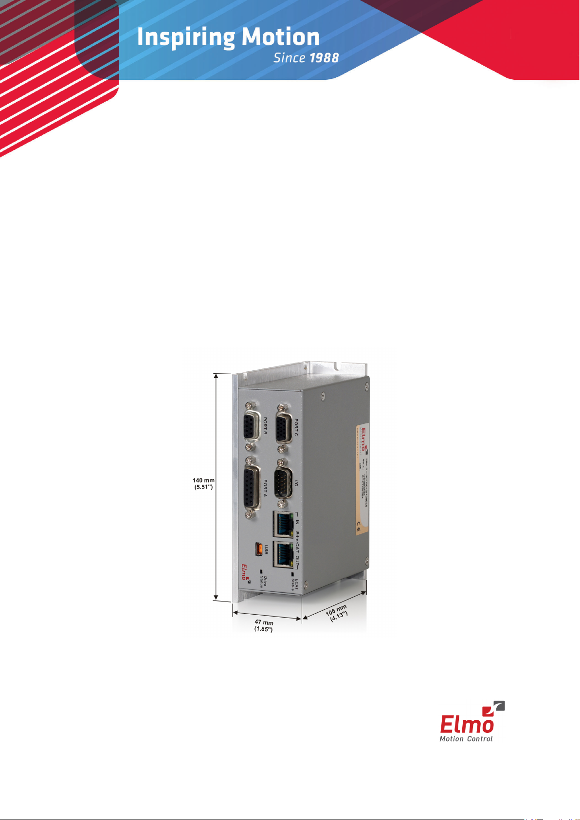
4.1 Physical Specifications
Feature Units All Types
Weight g (oz) 650 g (22.9 oz) for standard L shape
1100 g (38.8 oz) for L shape fins and fan
Dimensions mm (in) 105 x 140 x 47 (4.13" x 5.51" x 1.85")
Mounting method Panel / Wall Mounted
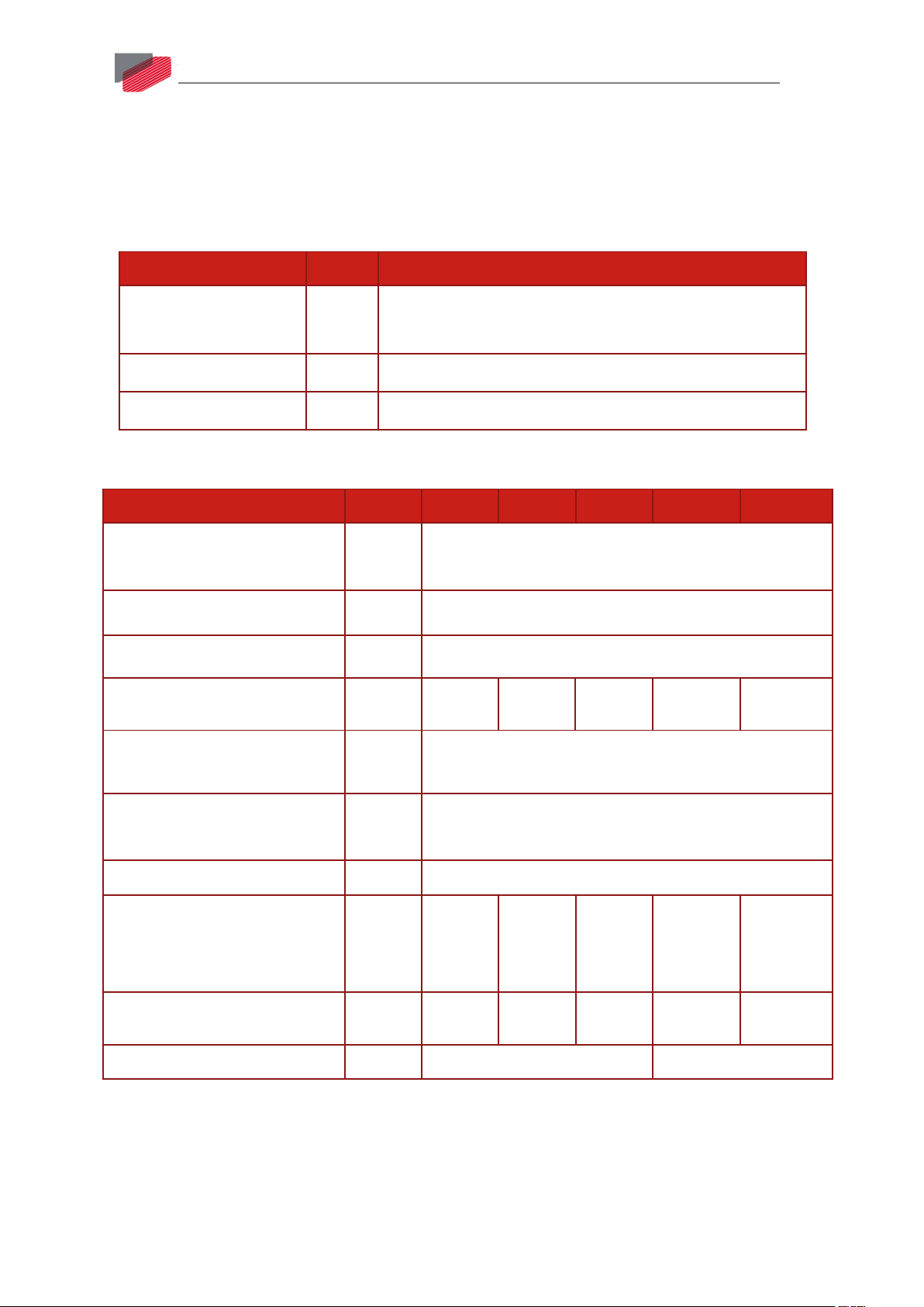
4.2 Technical Data for the 400 V Type
Feature Units 6/400 12/400 16/400 R17/400 R22/400
Minimum supply voltage
0 or 1 Option in P/N: 100
Nominal supply voltage
Maximum supply voltage
Maximum continuous power
output
Efficiency at rated power (at
nominal conditions)
Auxiliary supply voltage option
Auxiliary power supply
Continuous current limit (Ic)
Amplitude sinusoidal/DC
trapezoidal commutation
Sinusoidal continuous RMS
current limit (Ic)
Peak current limit
Only for Control Supply A/H/S/T Option Models
|Physical Specifications|www.elmomc.com
Page 10
Gold DC Trombone Installation Guide
Table of Contents
VDC
A, H, S, or T Option in P/N*: 95+
VDC
560 for 400 VAC
VDC
780
kW 5 7.5 7 10
%
> 98
VDC
18 V to 30 V
VA
7
A 8 12
11
16
A
5.7
8.5
7.8
11.3
A
2 x Ic
No peak
MAN-G-DCTROI G-EC (Ver. 1.900)
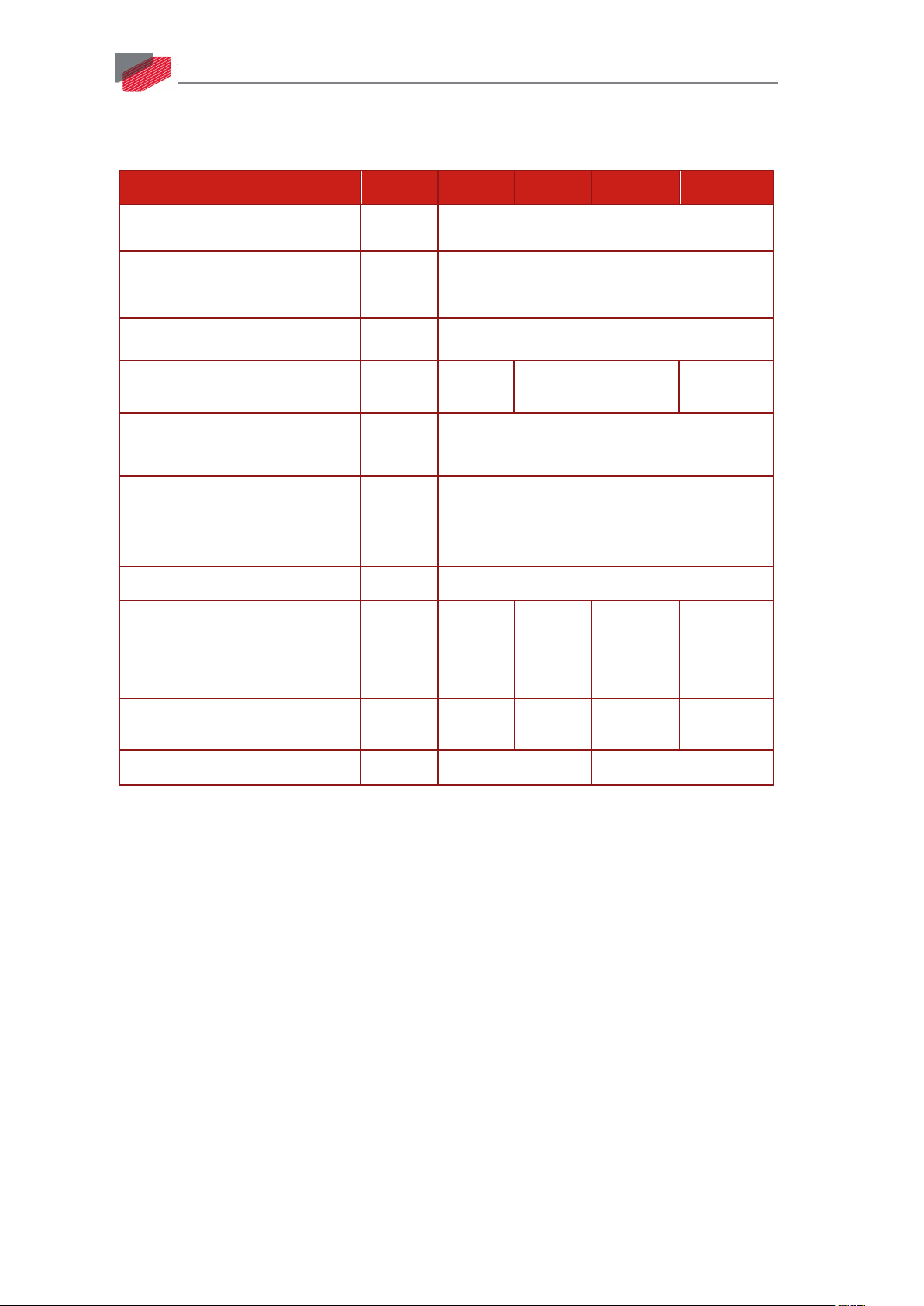
4.3 Technical Data for the 800 V Type
Feature Units 8/800 12/800 R11/800 R16/800
Minimum supply voltage
Nominal supply voltage
680 for 480 VAC
Maximum supply voltage
Maximum continuous power
output
Efficiency at rated power (at
nominal conditions)
Auxiliary supply voltage option
Only for Control Supply A/H/S/T Option
Models
10
Auxiliary power supply
Continuous current limit (Ic)
Amplitude sinusoidal/DC
trapezoidal commutation
Sinusoidal continuous RMS
current limit (Ic)
Peak current limit
*See section Catalog Number for details on the part number. The A, H, S, or T Option appears in
models where there is a 24 V control supply. If there is a 0 or 1 Option, the control power supply
operates from the main power.
Note on current ratings: The current ratings of the Gold DC Trombone are given in units of DC
amperes (ratings that are used for trapezoidal commutation or DC motors). The RMS (sinusoidal
commutation) value is the DC value divided by 1.41.
||Technical Data for the 800 V Type|www.elmomc.com
Page 11
Gold DC Trombone Installation Guide
Table of Contents
Auxiliary power supply
Isolated DC source only
Auxiliary supply input voltage
18 VDC to 30 VDC
Auxiliary supply input power
7
MAN-G-DCTROI G-EC (Ver. 1.900)
4.4 Auxiliary Supply
Feature Details
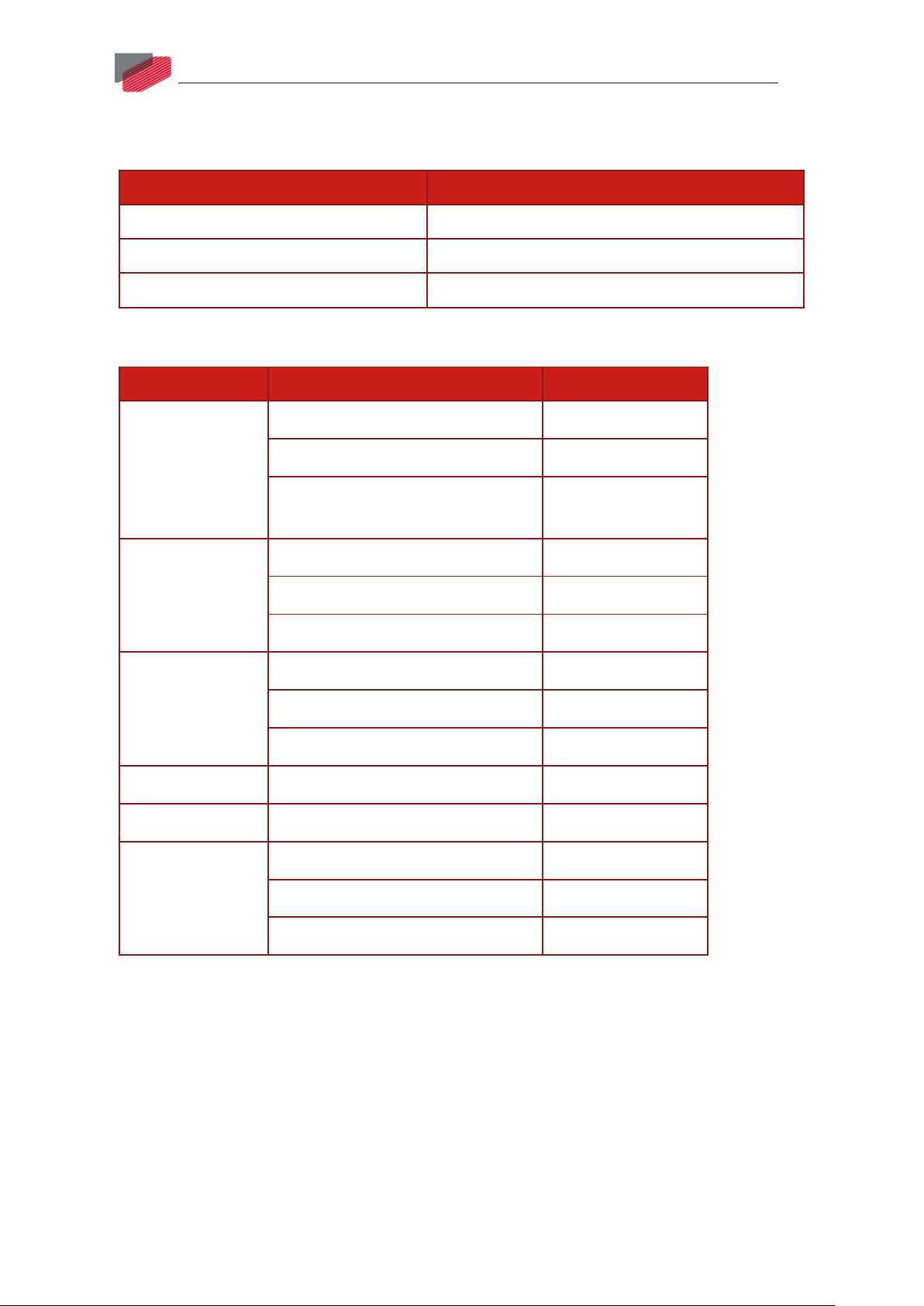
4.5 Product Features
Main Feature Details Presence and No.
11
STO
Digital Input
Option
Digital Output
Option
Analog Input
Feedback
Communication
Option
TTL, or
PLC Source, or
PLC Sink (is not fully certified, and
not recommended for new designs)
TTL, or
PLC Source, or
PLC Sink
TTL, or
PLC Source, or
PLC Sink
Differential ±10V
Standard Port A, B, & C
USB
EtherCAT, or
√
√
√
6
6
6
4
4
4
1
√
√
√
||Auxiliary Supply|www.elmomc.com
CAN
√
Page 12
Gold DC Trombone Installation Guide
Table of Contents
Chapter 5:
Installation
MAN-G-DCTROI G-EC (Ver. 1.900)
12
The Gold DC Trombone must be installed in a suitable environment and properly connected to its
voltage supplies and the motor.
5.1 Unpacking the Drive Components
Before you begin working with the Gold DC Trombone, verify that you have all of its components, as
follows:
• The Gold DC Trombone servo drive
• The Elmo Application Studio (EAS) software and software manual
The Gold DC Trombone is shipped in a cardboard box with Styrofoam protection.
To unpack the Gold DC Trombone:
1. Carefully remove the servo drive from the box and the Styrofoam.
2. Check the drive to ensure that there is no visible damage to the instrument. If any damage
has occurred, report it immediately to the carrier that delivered your drive.
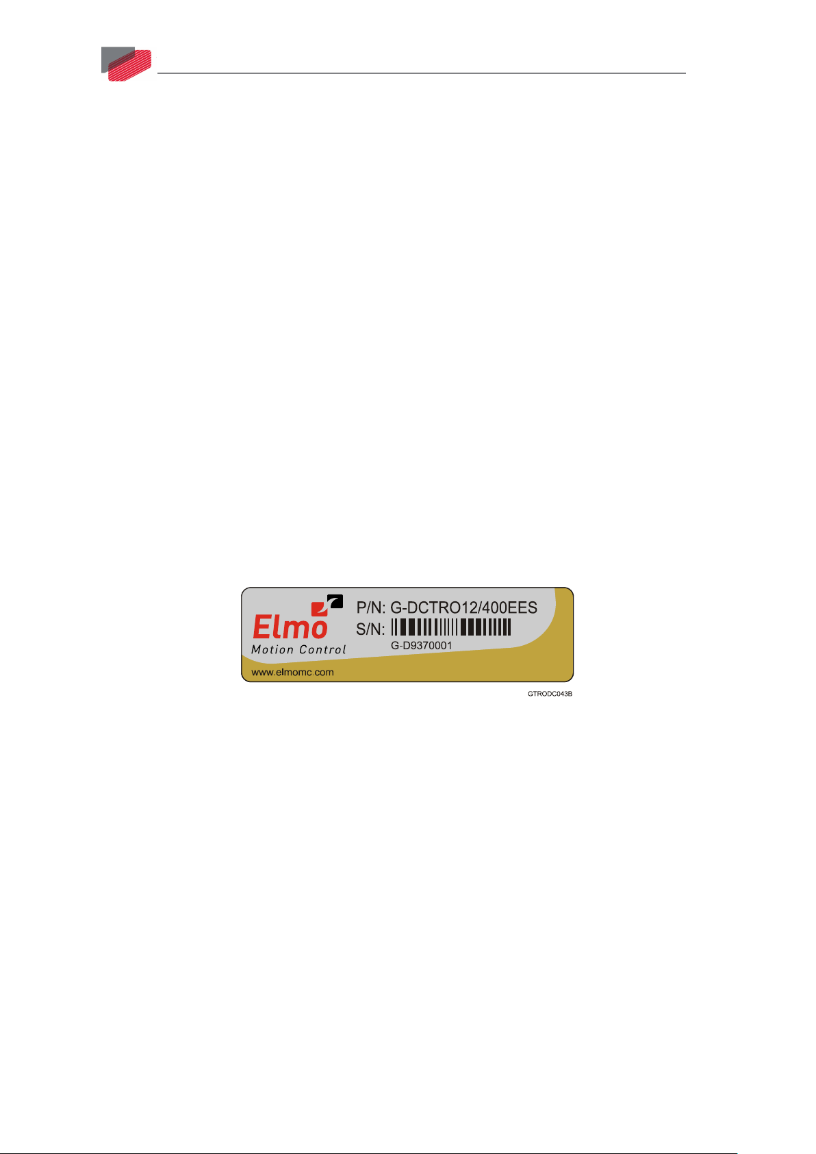
3. To ensure that the Gold DC Trombone you have unpacked is the appropriate type for your
requirements, locate the part number sticker on the side of the Gold DC Trombone. It looks
like this:
Figure 1: Gold DC Trombone Part Number Sticker
4. Verify that the Gold DC Trombone type is the one that you ordered, and ensure that the
voltage meets your specific requirements.
The part number at the top provides the type designation. Refer to the appropriate part
number in the section Catalog Number at the beginning of the installation guide.
|Unpacking the Drive Components|www.elmomc.com
Page 13
Gold DC Trombone Installation Guide
Table of Contents
MAN-G-DCTROI G-EC (Ver. 1.900)
5.2 Connector Types
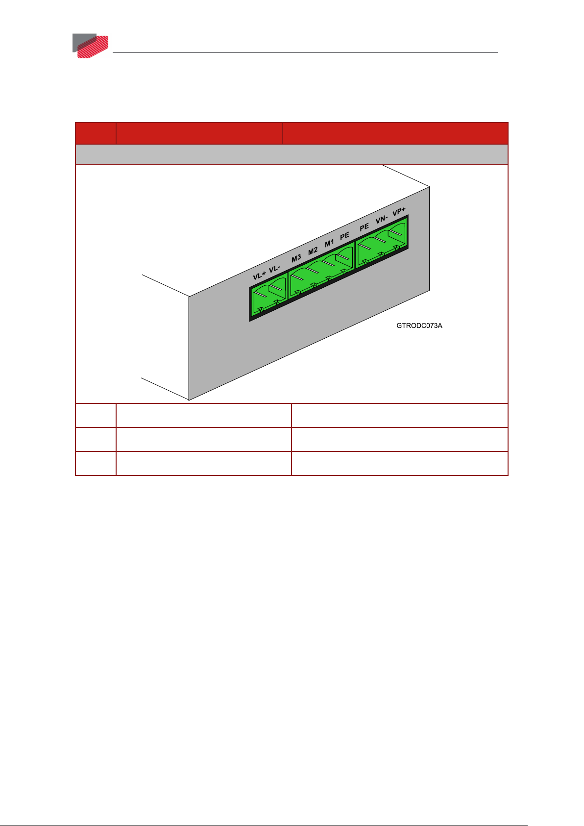
The Gold DC Trombone has the following ten connectors.
Pins Type Function
Bottom Connectors
13
2 5.08 mm Phoenix high current 24 V
4 7.62 mm Phoenix high current Motor Connector
3 7.62 mm Phoenix high current Power Connector
||Connector Types|www.elmomc.com
Page 14
Gold DC Trombone Installation Guide
Table of Contents
MAN-G-DCTROI G-EC (Ver. 1.900)
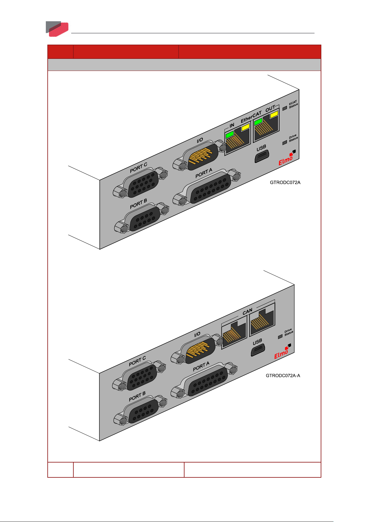
Pins Type Function
Front Connectors
14
Front Connectors - EtherCAT
Front Connectors - CAN
15 Socket D-Type Port A
||Connector Types|www.elmomc.com
Page 15
Gold DC Trombone Installation Guide
Table of Contents
MAN-G-DCTROI G-EC (Ver. 1.900)
Pins Type Function
9 Socket D-Type Port B
15 Socket High Density D-Type Port C and Safety
15 Pin High Density D-Type I/O
4 USB Device Type Mini B USB communication
EtherCAT Version
8 RJ-45 EtherCAT_IN/Ethernet communication
8 RJ-45 EtherCAT OUT communication
CAN Version
8 RJ-45 CAN
8 RJ-45 CAN
15
Table 1: Connector Types
The pinouts in Chapter 6: Wiring describe the function of each pin in the Gold DC Trombone
connectors that are listed in Table 1.
5.2.1 Mating Connector Types
Mating Pin Connector Function Manufacturing P/N (Pheonix)
2 Pin VL MSTB 2,5/ 2-ST-5,08
3 Pin Main DC Input GMSTB 2,5 HCV/ 3-ST-7,62
4 Pin Motor Power GMSTB 2,5 HCV/ 4-ST-7,62
||Connector Types|www.elmomc.com
Page 16
Gold DC Trombone Installation Guide
Table of Contents
MAN-G-DCTROI G-EC (Ver. 1.900)
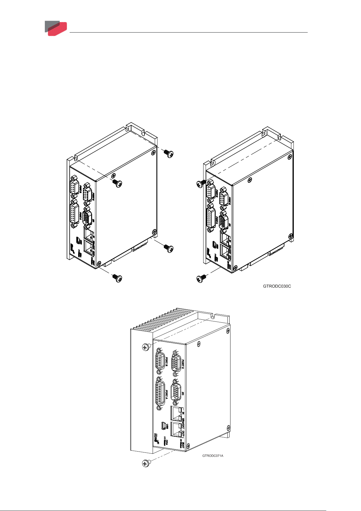
5.3 Mounting the Gold DC Trombone
The Gold DC Trombone has been designed for two standard mounting options:
• Wall Mount along the back (can also be mounted horizontally on a metal surface)
• Book Shelf along the side
M4 round head screws, one through each opening in the heat sink, are used to mount the Gold DC
Trombone (see the diagram below).
16
Figure 2: Mounting the Gold DC Trombone with standard L-shape heat-sink
Figure 3: Mounting the Gold DC Trombone with L-shape heat-sink fins and fan
||Mounting the Gold DC Trombone|www.elmomc.com
Page 17

Gold DC Trombone Installation Guide
Table of Contents
MAN-G-DCTROI G-EC (Ver. 1.900)
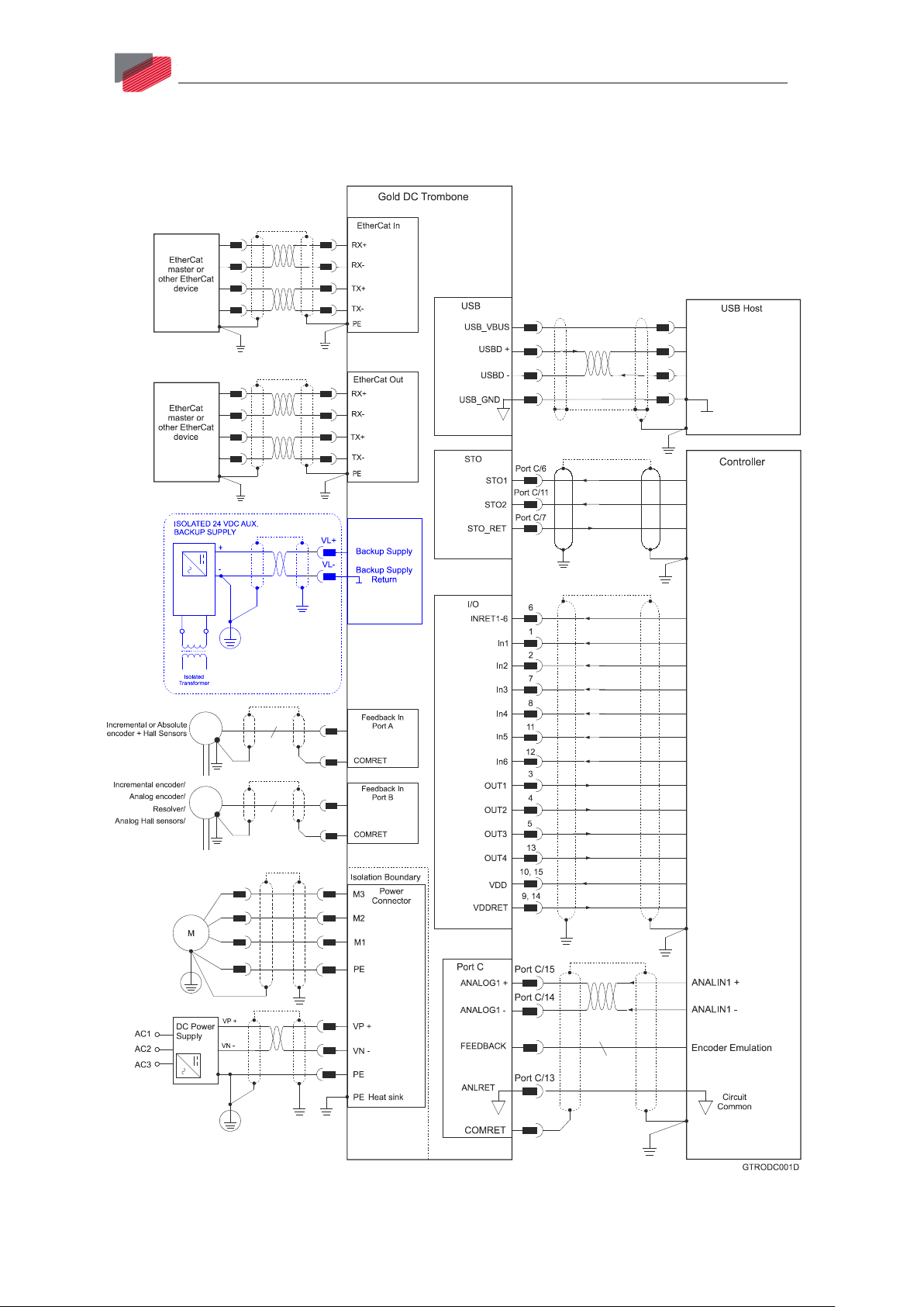
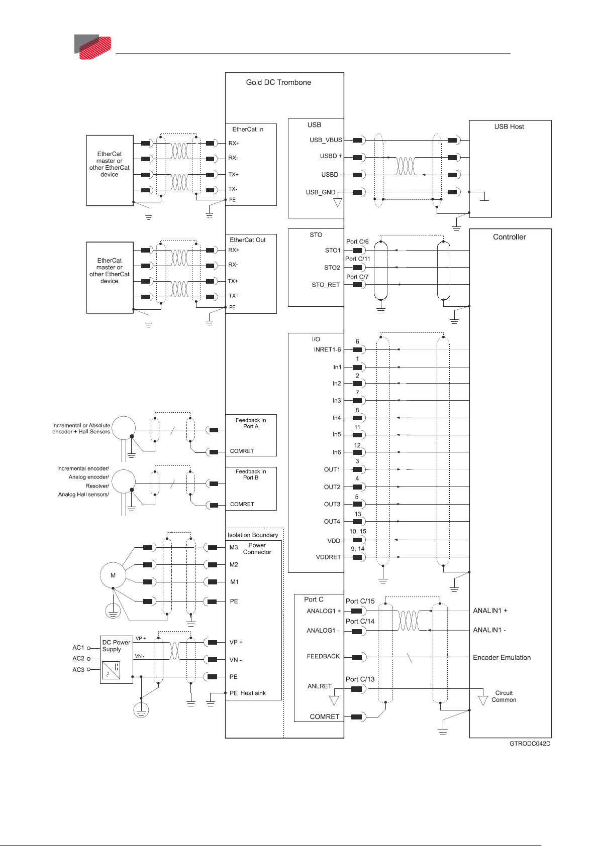
5.4 Connection Diagrams
There are two connection diagrams for EtherCAT and two for CAN that show the two different ways
of connecting the power supply:
• 400 V and 800 V A, H, S, or T options (the catalog number has an A, H, S, or T option) that
feature backup functionality and require an auxiliary 24 V backup supply. The drive will not be
operative without the external 24 VDC supply.
• 400 V model without backup functionality with a 0 or 1 option. The drive’s internal DC/DC
converter is fed from the VP+ and VN- of the internal drive’s bus line.
17
||Connection Diagrams|www.elmomc.com
Page 18
Gold DC Trombone Installation Guide
Table of Contents
MAN-G-DCTROI G-EC (Ver. 1.900)
5.4.1 Connection Diagrams for EtherCAT Version
The following describes the connection diagrams for the EtherCAT version.
18
Figure 4: Gold DC Trombone EtherCAT Connection Diagram – with Backup Functionality
(A, H, S, or T options)
||Connection Diagrams|www.elmomc.com
Page 19
Gold DC Trombone Installation Guide
Table of Contents
MAN-G-DCTROI G-EC (Ver. 1.900)
19
Figure 5: Gold DC Trombone EtherCAT Connection Diagram – 400 V without Backup Functionality
for Model Drives with 0 or 1 Options
||Connection Diagrams|www.elmomc.com
Page 20
Gold DC Trombone Installation Guide
Table of Contents
MAN-G-DCTROI G-EC (Ver. 1.900)
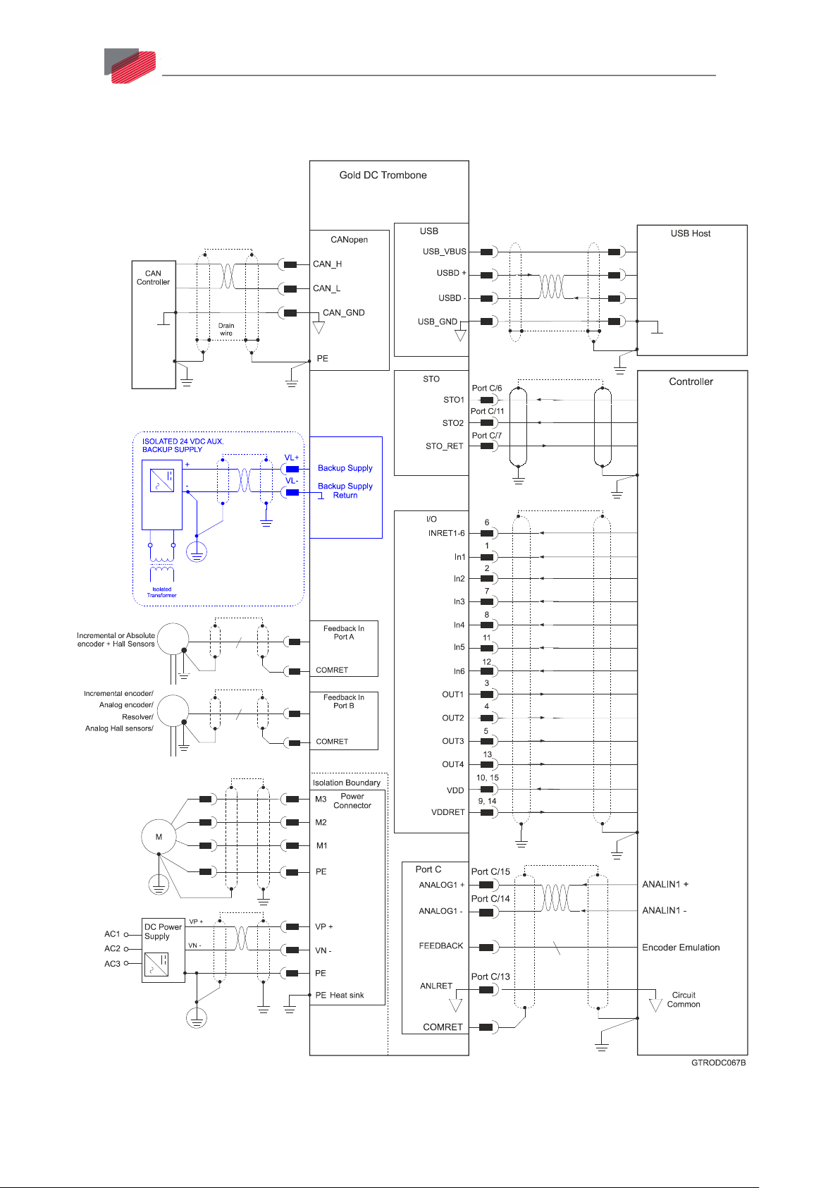
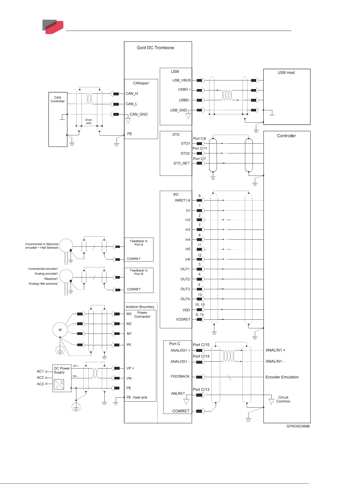
5.4.2 Connection Diagrams for CAN Version
The following describes the connection diagrams for the CAN version.
20
Figure 6: Gold DC Trombone CAN Connection Diagram – with Backup Functionality
(A, H, S, or T options)
||Connection Diagrams|www.elmomc.com
Page 21
Gold DC Trombone Installation Guide
Table of Contents
MAN-G-DCTROI G-EC (Ver. 1.900)
21
Figure 7: Gold DC Trombone CAN Connection Diagram – 400 V without Backup Functionality
for Model Drives with 0 or 1 Options
||Connection Diagrams|www.elmomc.com
Page 22

Gold DC Trombone Installation Guide
Table of Contents
Chapter 6: Wiring
MAN-G-DCTROI G-EC (Ver. 1.900)
Once the product is mounted, you are ready to wire the device. Proper wiring, grounding and
shielding are essential for ensuring safe, immune and optimal servo performance of the drive.
The following table legend describes the wiring symbols detailed in all installation guides.
Wiring Symbol Description
Earth connection (PE)
Protective Earth Connection
Common at the Controller
Shielded cable with drain wire.
The drain wire is a non-insulated wire
that is in direct contact with the braid
(shielding).
22
Shielded cable with drain wire
significantly simplifies the wiring and
earthing.
Shielded cable braid only, without drain
wire.
Twisted-pair wires
||Connection Diagrams|www.elmomc.com
Page 23

Gold DC Trombone Installation Guide
Table of Contents
MAN-G-DCTROI G-EC (Ver. 1.900)
Wiring Symbol Description
D-type Connector: The cable`s braid
(Shield) must be connected to the D-sub
shell (metal housing)
Encoder Earthing.
T The cable`s shield is connected to the
chassis (PE) in the connector.
Earthing the Encoder and connecting
the Earth (PE) to the drive COMRET is
mandatory to insure reliable operation,
high noise immunity and rejection of
voltage common mode interferences.
23
||Connection Diagrams|www.elmomc.com
Page 24

Gold DC Trombone Installation Guide
Table of Contents
MAN-G-DCTROI G-EC (Ver. 1.900)
6.1 Basic Recommendations
6.1.1 General
1. Use shielded cables. For best results, the cable should have an aluminum foil shield covered
by copper braid, and should contain a drain wire.
Use 24, 26 or 28 AWG twisted-pair shielded with drain wire cables.
2. Keep the cable as short as possible.
Do not mount the power cables of the motor and power bus in the proximity of the control
and feedback cables.
3. Ensure that in normal operating conditions, the “earth connection” wires and shield of the
control cables carry no current. The only time these conductors carry current is under
abnormal conditions, when electrical equipment has become a potential shock or fire
hazard while conducting external EMI interferences directly to ground, in order to prevent
them from affecting the drive. Failing to meet this requirement might result in
drive/controller/host failure.
24
4. After completing the wiring, carefully inspect all wires to ensure tightness, good solder of
joints and general safety.
Figure 8: D-Type Cable Assemblies
5. Use only a D-Sub connector with a metal housing (Figure 8).
6. Make sure the braid shield is in tight contact with the metal housing of the D-type
connector (Figure 8).
||Basic Recommendations|www.elmomc.com
Page 25

Gold DC Trombone Installation Guide
Table of Contents
MAN-G-DCTROI G-EC (Ver. 1.900)
6.1.2 Feedback Cable Port A and Port B Connector
1. On the motor side connections, ground the shield to the motor chassis.
2. At least One COMRET (Common Return) must be connected to the PE.
Implement the following steps to connect the COMRET to the PE:
a. At the drive, connect the feedback drain wire to one of the COMRET terminals in the
D-Type feedback connector (Figure 9).
b. At the motor, connect the feedback cable drain wire to the GND motor chassis
terminal of the feedback connector.
The drawings below display two earth connections.
25
Figure 9: Feedback Port A and B Cable Assemblies
||Basic Recommendations|www.elmomc.com
Page 26

Gold DC Trombone Installation Guide
Table of Contents
MAN-G-DCTROI G-EC (Ver. 1.900)
6.1.3 Feedback Cable Port C Connector
1. At the controller side connections, follow the controller manufacturer’s recommendations
concerning the shield.
2. The connection of the Drain wire to the Port C is not mandatory.
26
Figure 10: Feedback Port C Cable Assemblies
6.1.4 IO Cable Connector
It is recommended to use shielded cable, but is not mandatory.
Figure 11: Feedback IO Cable Assemblies
||Basic Recommendations|www.elmomc.com
Page 27

Gold DC Trombone Installation Guide
Table of Contents
MAN-G-DCTROI G-EC (Ver. 1.900)
6.1.5 STO (Port C) Cable Connector
It is recommended to use shielded cable, but is not mandatory.
Figure 12: STO Cable Assemblies
27
||Basic Recommendations|www.elmomc.com
Page 28

Gold DC Trombone Installation Guide
Table of Contents
MAN-G-DCTROI G-EC (Ver. 1.900)
6.2 Motor Power Connector Pinouts
See Chapter 8 in the in the MAN-G-Panel Mounted Drives Hardware manual for full details.
Pin Function Cable
Brushless Motor Brushed DC Motor
M3 Motor phase Motor Motor
M2 Motor phase Motor Motor
M1 Motor phase Motor N/C
PE Protective Earth Motor Motor
28
4-Pin Pluggable 7.62 mm Phoenix High Current
Table 2: Connectors for Motor
4-Pin Phoenix Plug-in
Connector
||Motor Power Connector Pinouts|www.elmomc.com
Page 29

Gold DC Trombone Installation Guide
Table of Contents
MAN-G-DCTROI G-EC (Ver. 1.900)
To power the drive, connect the M1, M2, M3, and PE pins on the Gold DC Trombone. The phase
connection is arbitrary as Elmo Application Studio II (EAS II) will establish the proper commutation
automatically during setup. When tuning a number of drives, you can copy the setup file to the
other drives and thus avoid tuning each drive separately. In this case the motor-phase order must
be the same as on the first drive.
• For best immunity, it is highly recommended to use a 4-wire shielded (not twisted) cable for
the motor connection. The gauge is determined by the actual current consumption of the
motor.
• Connect the cable shield to the closest ground connection at the motor end.
• For better EMI performance, the shield should be connected to Protective Earth (PE
terminal).
• Ensure that the motor chassis is properly grounded.
29
Figure 13: Brushless Motor Power Connection Diagram
Figure 14: Brushed Motor Power Connection Diagram
||Motor Power Connector Pinouts|www.elmomc.com
Page 30

Gold DC Trombone Installation Guide
Table of Contents
3-Pin Pluggable 7.62 mm Phoenix High Current
MAN-G-DCTROI G-EC (Ver. 1.900)
6.3 Main Power
The Gold DC Trombone receives power from main supply and delivers power to the motor.
See Chapter 8 in the in the MAN-G-Panel Mounted Drives Hardware manual for full details.
Pin Function Cable
PE Protective Earth DC Power
VN- DC Negative Power input DC Power
VP+ DC Positive Power input DC Power
30
3-Pin Phoenix Plug-in Connector
Table 3: Connectors for Main Power
The DC power for the Gold DC Trombone is delivered from a separated rectifying unit (supplied by
the user). Elmo recommends using the Tambourine rectifier specifically designed for use with Elmo
drives which offers a range of versatile options.
The following sections contain topology recommendations for implementing three-phase and a
single-phase supply chains.
The power stage of the Gold DC Trombone is fully isolated from the other sections of the Gold DC
Trombone, such as the control-stage and the heat sink. This isolation allows the user to connect
the common of the control section to the PE, a connection which significantly contributes to
proper functionality, safety and EMI immunity, leading to better performance of the Gold DC
Trombone.
In addition, this isolation simplifies the requirements of the DC power supply that is used to power
the DC bus of the Gold DC Trombone, by allowing it to operate with a non-isolated DC power source
(a direct-to-mains connection) which eliminates the need for a bulky and expensive isolation
transformer.
However, as well as operating from a non-isolated/direct-to-mains DC power supply, the Gold DC
Trombone can also operate from an isolated power supply or batteries.
When rectifying an AC voltage source, the AC voltage level must be limited to 270 VAC so as not to
exceed the maximum 390 VDC in the case of a 400 VDC drive, or 528 VAC so as not to exceed the
maximum 747 VDC in the case of an 800 VDC drive.
||Main Power|www.elmomc.com
Page 31

Gold DC Trombone Installation Guide
Table of Contents
MAN-G-DCTROI G-EC (Ver. 1.900)
6.3.1 Direct-to-Mains Power Source (Non-Isolated Rectifier)
This section relates to the configuration of the drive, which is connected directly to the mains.
To connect the non-isolated AC power supply:
1. For best noise immunity, a shielded (not twisted) cable is recommended (not mandatory) for
the DC input cable.
2. A 3-wire shielded cable should be used:
a. Connect the main input cable to the VP+ and VN- terminals of the main input connector.
b. For safety requirements, the green/yellow-wire must be connected to the protective earth
(PE terminal). Connect the Protective Earth wire to the PE terminal on the main DC
connector.
c. For better EMI performance, the shield should be connected to Protective Earth (PE).
3. The gauge of the cable strands is determined by the actual current of the drive.
31
Caution For all the following Topologies:
• Do not connect VN- to PE. In a direct-to-mains connection the VN- must no t be
connected to the PE, as this will cause irreparable damage to the system.
• Take care and note that in a direct-to-mains connection the Neutral point is not
the most negative voltage level. It is the mid-point level of the rectified DC bus.
||Main Power|www.elmomc.com
Page 32

Gold DC Trombone Installation Guide
Table of Contents
MAN-G-DCTROI G-EC (Ver. 1.900)
6.3.2 Three-Phase Direct-to-Mains Connection Topology
32
Figure 15: Non-Isolated Three-Phase Connection Topology
||Main Power|www.elmomc.com
Page 33

Gold DC Trombone Installation Guide
Table of Contents
MAN-G-DCTROI G-EC (Ver. 1.900)
6.3.3 Single-Phase Direct-to-Mains Connection Topology
33
Figure 16: Non-Isolated Single-Phase Connection Topology
The Power Supply is connected directly to the mains AC line.
||Main Power|www.elmomc.com
Page 34

Gold DC Trombone Installation Guide
Table of Contents
MAN-G-DCTROI G-EC (Ver. 1.900)
6.3.4 Multiple Connections Topology
In a multi-axis application it is likely that a single power supply can feed several drives in parallel.
The power supply is connected directly to the mains AC line and it feeds more than one drive.
This topology is efficient and cost saving, by reducing the number of power supplies and the
amount of wiring. Most importantly it utilizes an energy sharing environment among all the drives
that share the same DC bus network.
34
Figure 17: Non-Isolated Three-Phase Multiple Connection Topology
||Main Power|www.elmomc.com
Page 35

Gold DC Trombone Installation Guide
Table of Contents
MAN-G-DCTROI G-EC (Ver. 1.900)
6.3.5 Battery Power Supply
Figure 18: Battery Connection Topology
Caution: When using batteries, it is recommended to connect the negative pole
to the PE.
When doing so, the charger of the battery must be isolated from the mains by
an isolation transformer.
35
||Main Power|www.elmomc.com
Page 36

Gold DC Trombone Installation Guide
Table of Contents
MAN-G-DCTROI G-EC (Ver. 1.900)
6.4 Auxiliary Power
Optional Backup Supply in A, H, S, or T option drives.
See Chapter 8 in the in the MAN-G-Panel Mounted Drives Hardware manual for full details.
Pin Function Cable
A, H, S, or T option type
VL+ +24 V Auxiliary Supply Input Positive DC Power
VL- 24 V RET Auxiliary Supply Input Return DC Power
36
2-Pin Phoenix Plug-in Connector
2-Pin Pluggable 5.08 mm Phoenix High Current
Table 4: Auxiliary Power Connector
In drives that have a 0 or 1 Option (only for 400 V model) in the catalog number, a smart controlsupply algorithm enables the Gold DC Trombone to operate with the main power supply only, with
no need for an auxiliary supply voltage to supply the drive’s logic section.
Note that in such a model there is no backup ability at all.
If backup functionality is required to store control parameters in the event of a mains power
outage, then an A, H, S, or T options Gold DC Trombone should be used, with an external 24 VDC
isolated supply connected to it.
Note that the A, H, S, or T options Gold DC Trombone always requires an external 24 VDC power
supply, regardless of whether or not backup functionality is required.
Connect the auxiliary 24 VDC power supply as described below.
To connect the 24 VDC backup supply:
1. Use a 24 AWG twisted pair shielded cable. The shield should have copper braid.
2. The source of the 24VDC backup supply must be isolated with an isolation transformer.
3. For safety and EMI reasons, connect the return of the 24VDC backup supply to the closest
ground (PE).
4. Connect the cable shield to the closest ground (PE) near the power source.
5. Before applying power, first verify that the polarity of the connection is correct.
||Auxiliary Power|www.elmomc.com
Page 37

Gold DC Trombone Installation Guide
Table of Contents
MAN-G-DCTROI G-EC (Ver. 1.900)
Figure 19: Auxiliary 24 VDC Backup Supply Connection Diagram
37
||Auxiliary Power|www.elmomc.com
Page 38

Gold DC Trombone Installation Guide
Table of Contents
MAN-G-DCTROI G-EC (Ver. 1.900)
6.5 Port A
See Section 10.3 in the in the MAN-G-Panel Mounted Drives Hardware manual for full details.
Incremental Encoder Absolute Serial Encoder
38
Pin on
Signal Function Signal Function
Port A
12,4 +5V Encoder +5V supply +5V Encoder +5V supply
3,9,11,13 COMRET Common return COMRET Common Return
6 PortA_ENC_A+ Channel A+ ABS_CLK+ Abs encoder clock +
5 PortA_ENC_A- Channel A- ABS_CLK- Abs encoder clock -
15 PortA_ENC_B+ Channel B+ ABS_DATA+ Abs encoder data +
14 PortA_ENC_B- Channel B- ABS_DATA- Abs encoder data -
8 PortA_ENC_INDEX+ Index+ Reserved Reserved
7 PortA_ENC_INDEX- Index- Reserved Reserved
2 HA Hall sensor A HA Hall sensor A
10 HB Hall sensor B HB Hall sensor B
1 HC Hall sensor C HC Hall sensor C
Pin Positions
15-Socket D-Type Female Connector
15-Pin D-Type Male
Connector
Table 5: Port A Pin Assignments
||Port A|www.elmomc.com
Page 39

Gold DC Trombone Installation Guide
Table of Contents
MAN-G-DCTROI G-EC (Ver. 1.900)
6.5.1 Incremental Encoder
The following figure describes the connections at Port A for the Incremental encoder.
39
Figure 20: Port A D-Type Incremental Encoder Input – Recommended Connection Diagram
6.5.2 Hall Sensor
The following figure describes the connections at Port A for the Hall Sensor.
Figure 21: Hall Sensor Connection Diagram
||Port A|www.elmomc.com
Page 40

Gold DC Trombone Installation Guide
Table of Contents
MAN-G-DCTROI G-EC (Ver. 1.900)
6.5.3 Absolute Serial Type Encoder
The following figures describe the connections at Port A for the Absolute Serial type encoders.
40
Figure 22: Absolute Serial Encoder – Recommended D-Type Connection Diagram for EnDAT,
Biss, and SSI
Figure 23: Absolute Serial Encoder – Recommended D-Type Connection Diagram for Sensors
Supporting Data Line Only (NRZ types, e.g., Panasonic / Mitutoyo / Sanyo Danki / Tamagawa)
||Port A|www.elmomc.com
Page 41

Gold DC Trombone Installation Guide
Table of Contents
MAN-G-DCTROI G-EC (Ver. 1.900)
41
Figure 24: Absolute Serial Encoder – Recommended D-Type Connection Diagram for Stegmann
Hiperface
||Port A|www.elmomc.com
Page 42

Gold DC Trombone Installation Guide
Table of Contents
MAN-G-DCTROI G-EC (Ver. 1.900)
6.6 Port B
See Section 10.4 in the in the MAN-G-Panel Mounted Drives Hardware manual for full details.
42
Incremental or
Resolver
Interpolated Analog Encoder
G-DCTROXXX/YYYYXEXX G-DCTROXXX/YYYYXRXX
Pin on
Signal Function Signal Function
Port B
4 +5V Encoder +5V supply NC
5,9 COMRET Common Return COMRET Common Return
1 PortB_ENC_A+/SIN+ Incremental Encoder
A+ / Sine+
6 PortB_ENC_A-/SIN- Channel A- / Sine- SIN- Sine-
2 PortB_ENC_B+/COS+ Channel B+ / Cosine+ COS+ Cosine+
7 PortB_ENC_B-/COS- Channel B- / Cosine- COS- Cosine-
3 PortB_ENC_INDEX+ Index+ RESOLVER_OUT+ Vref f=1/TS, 50 mA
8 PortB_ENC_INDEX- Index - RESOLVER_OUT- Vref complement
SIN+ Sine+
Max.
f= 1/TS, 50 mA Max.
Pin Positions
9-Pin D-Type Female Connector
Table 6: Port B Pin Assignments
||Port B|www.elmomc.com
9-Pin D-Type Male
Connector
Page 43

Gold DC Trombone Installation Guide
Table of Contents
MAN-G-DCTROI G-EC (Ver. 1.900)
6.6.1 Incremental Encoder
The following figure describes the connections at Port B for the Incremental encoder.
43
Figure 25: Port B Incremental Encoder Input – Recommended D-Type Connection Diagram
||Port B|www.elmomc.com
Page 44

Gold DC Trombone Installation Guide
Table of Contents
MAN-G-DCTROI G-EC (Ver. 1.900)
6.6.2 Interpolated Analog Encoder
The following figure describes the connections at Port B for the Interpolated Analog encoder.
44
Figure 26: Port B - Interpolated Analog Encoder D-Type Connection Diagram
||Port B|www.elmomc.com
Page 45

Gold DC Trombone Installation Guide
Table of Contents
MAN-G-DCTROI G-EC (Ver. 1.900)
6.6.3 Resolver
The following figure describes the connections at Port B for the Resolver encoder.
45
Figure 27: Port B – Resolver D-Type Connection Diagram
||Port B|www.elmomc.com
Page 46

Gold DC Trombone Installation Guide
Table of Contents
MAN-G-DCTROI G-EC (Ver. 1.900)
6.7 Port C, Analog Input, and STO
The Port C connector includes the following functions:
• Port C: Refer to Sections 10.5 in the in the MAN-G-Panel Mounted Drives Hardware manual
for full details
• STO: See Chapter 9 in the in the MAN-G-Panel Mounted Drives Hardware manual for full
details.
• Analog input: See Section 11.2 in the in the MAN-G-Panel Mounted Drives Hardware manual
for full details.
46
Pin on
Signal Function
Port C
1 PortC_ENCO_A+ Buffered Channel A+ output/Pulse+/PWM+
2 PortC_ENCO_A- Buffered Channel A- output / Pulse- / PWM-
3 PortC_ENCO_B+ Buffered Channel B+ output / Dir+
4 PortC_ENCO_B- Buffered Channel B- output / Dir-
5 PortC_ENCO_ Index+ Buffered Channel INDEX+ output
6 STO1 STO 1 input (default 24 V)
7, 12 STO_RET STO signal return
8 Reserved Reserved
9 COMRET Common return
10 PortC_ENCO _ Index- Buffered Channel INDEX- output
11 STO2 STO 2 input (default 24 V)
13 ANLRET Analog ground
14 ANALOG1- Analog input 1-
15 ANALOG1+ Analog input 1+
||Port C, Analog Input, and STO|www.elmomc.com
Page 47

Gold DC Trombone Installation Guide
Table of Contents
MAN-G-DCTROI G-EC (Ver. 1.900)
Pin Positions
47
15-Socket High Density D-Type Connector
Table 7: Port C Feedback Out and STO Analog In
15-Pin High Density
D-Type Male
Connector
||Port C, Analog Input, and STO|www.elmomc.com
Page 48

Gold DC Trombone Installation Guide
Table of Contents
MAN-G-DCTROI G-EC (Ver. 1.900)
6.7.1 Port C
The following figure describes the connections at Port C for the Emulated Encoder Differential.
48
Figure 28: Emulated Encoder Differential Output – Recommended D-Type Connection Diagram
6.7.2 Analog Input
The following circuit describes the internal interface of the Analog input.
Figure 29: Differential Analog D-Type Input
||Port C, Analog Input, and STO|www.elmomc.com
Page 49

Gold DC Trombone Installation Guide
Table of Contents
MAN-G-DCTROI G-EC (Ver. 1.900)
6.7.3 STO
The following circuits describe the STO wiring options.
6.7.3.1 Source Mode PLC Voltage Level
Figure 30: STO D-Type Input Connection – PLC Source Option
49
6.7.3.2 TTL Mode TTL Voltage Level
Figure 31: STO Input Connection – TTL Option
||Port C, Analog Input, and STO|www.elmomc.com
Page 50

Gold DC Trombone Installation Guide
Table of Contents
MAN-G-DCTROI G-EC (Ver. 1.900)
6.7.3.3 SINK Mode – PLC Voltage Level
Refer to the diagrams below for the PLC Sink option connections which is not fully certified for STO.
This option is not recommended for new designs.
50
Figure 32: STO Input Connection – Sink Option
||Port C, Analog Input, and STO|www.elmomc.com
Page 51

Gold DC Trombone Installation Guide
Table of Contents
MAN-G-DCTROI G-EC (Ver. 1.900)
6.8 Digital Inputs and Outputs
Refer to Chapter 11 in the in the MAN-G-Panel Mounted Drives Hardware manual for full details.
Pin on I/O Signal Function
51
1 IN1
2 IN2
7 IN3
8 IN4
11 IN5
12 IN6
Programmable digital input 1 (event capture, home, general
purpose, RLS, FLS, INH, PWM & direction input, pulse &
direction input)
Programmable digital input 2 (event capture, home, general
purpose, RLS, FLS, INH, PWM & direction input, pulse &
direction input)
Programmable digital input 3 (event capture, home, general
purpose, RLS, FLS, INH, PWM & direction input, pulse &
direction input)
Programmable digital input 4 (event capture, home, general
purpose, RLS, FLS, INH, PWM & direction input, pulse &
direction input)
Programmable digital input 5 (event capture, home, general
purpose, RLS, FLS, INH, PWM & direction input, pulse &
direction input)
Programmable digital input 6 (event capture, home, general
purpose, RLS, FLS, INH, PWM & direction input, pulse &
direction input)
6 INRET1-6 Programmable inputs 1 - 6 return for standard version
Programmable positive inputs 1 - 6 for A or H option
3 OUT1 Programmable output 1
4 OUT2 Programmable output 2
5 OUT3 Programmable output 3
13 OUT4 Programmable output 4
10, 15 VDD
9, 14 VDDRET
Supply for out 1-4
Supply return for out 1-4
||Digital Inputs and Outputs|www.elmomc.com
Page 52

Gold DC Trombone Installation Guide
Table of Contents
MAN-G-DCTROI G-EC (Ver. 1.900)
Pin on I/O Signal Function
Pin Positions
52
15-Pin High Density D-Type Male Connector
Table 8: I/O Connector Pin Assignments
15-Pin High Density
D-Type Female
Connector
||Digital Inputs and Outputs|www.elmomc.com
Page 53

Gold DC Trombone Installation Guide
Table of Contents
MAN-G-DCTROI G-EC (Ver. 1.900)
6.8.1 Digital Input and Output TTL Mode
The following figure describes the connections at the I/O Port for the Digital Input and Output TTL
Mode.
53
Figure 33: Digital Input TTL Mode D-Type Connection Diagram
||Digital Inputs and Outputs|www.elmomc.com
Page 54

Gold DC Trombone Installation Guide
Table of Contents
MAN-G-DCTROI G-EC (Ver. 1.900)
54
Figure 34: Digital Output D-Type Connection Diagram – TTL Option
||Digital Inputs and Outputs|www.elmomc.com
Page 55

Gold DC Trombone Installation Guide
Table of Contents
MAN-G-DCTROI G-EC (Ver. 1.900)
6.8.2 Digital Input and Output PLC Source Mode
The following figure describes the connections at the I/O Port for the Digital Input and Output PLC
Mode.
55
Figure 35: Digital Input D-Type Connection Diagram – Source PLC Option
||Digital Inputs and Outputs|www.elmomc.com
Page 56

Gold DC Trombone Installation Guide
Table of Contents
MAN-G-DCTROI G-EC (Ver. 1.900)
56
Figure 36: Digital Output D-Type Connection Diagram – Source PLC Option
||Digital Inputs and Outputs|www.elmomc.com
Page 57

Gold DC Trombone Installation Guide
Table of Contents
MAN-G-DCTROI G-EC (Ver. 1.900)
6.8.3 Digital Input and Output Sink Mode
The following figure describes the connections at the I/O Port for the Digital Input and Output Sink
Mode.
57
Figure 37: Digital Input Sink Mode – PLC voltage level D-Type Connection Diagram
||Digital Inputs and Outputs|www.elmomc.com
Page 58

Gold DC Trombone Installation Guide
Table of Contents
MAN-G-DCTROI G-EC (Ver. 1.900)
58
Figure 38: Digital Output as Sink Configuration D-Type Connection Diagram
||Digital Inputs and Outputs|www.elmomc.com
Page 59

Gold DC Trombone Installation Guide
Table of Contents
MAN-G-DCTROI G-EC (Ver. 1.900)
6.9 USB 2.0
See Section 12.1 in the in the MAN-G-Panel Mounted Drives Hardware manual for full details.
Pin on USB Signal Function
1 USB VBUS USB VBUS 5V
2 USBD- USB _N line
3 USBD+ USB _P line
5 USB COMRET USB communication return
Pin Positions
59
Table 9: USB 2.0 Pin Assignments
USB Device Mini B Plug
Figure 39: USB Network Diagram
||USB 2.0|www.elmomc.com
Page 60

Gold DC Trombone Installation Guide
Table of Contents
MAN-G-DCTROI G-EC (Ver. 1.900)
6.10 Drive Status Indicator
The Gold DC Trombone is equipped with several light-emitting diode (LED) indicators.
60
The red/green dual LED is used for immediate indication of the following states:
• Initiation state: In this state the LED indicates whether the drive is in the boot state (blinking
red) or in the operational state (steady red).
• Working state: In this state the LED indicates whether the drive is in an amplifier failure state
(red) or is ready to enable the motor (green).
||Drive Status Indicator|www.elmomc.com
Page 61

Gold DC Trombone Installation Guide
Table of Contents
Fieldbus Type
Product Number
Signal
Function
MAN-G-DCTROI G-EC (Ver. 1.900)
6.11 EtherCAT Communications Version
Fieldbus communications are industrial network protocols for real-time distributed control that
allows connection of servo drives. The Gold DC Trombone supports the following EtherCAT fieldbus
type industrial network protocol:
EtherCAT G-DCTRO XX/YYYEXXX
6.11.1 EtherCAT In/Ethernet Pinouts
Refer to section 12.2 in the MAN-G-Panel Mounted Drives Hardware manual for more details.
Pin
1 EtherCAT_IN_TX+ EtherCAT in transmit +
2 EtherCAT_IN_TX- EtherCAT in transmit -
3 EtherCAT_IN_RX+ EtherCAT in receive +
61
4/5 N/A
6 EtherCAT_IN_RX- EtherCAT in receive -
7/8 N/A
Pin Positions
Standard CAT5e Ethernet
Cable
EtherCAT IN RJ-45 Connector
Table 10: EtherCAT In Connector Pin Assignments
||EtherCAT Communications Version|www.elmomc.com
Page 62

Gold DC Trombone Installation Guide
Table of Contents
Pin
Signal
Function
MAN-G-DCTROI G-EC (Ver. 1.900)
6.11.2 EtherCAT Out Pinouts
See Section 12.2 in the MAN-G-Panel Mounted Drives Hardware manual for the electrical diagram.
1 EtherCAT_OUT_TX+ EtherCAT out transmit +
2 EtherCAT_OUT_TX- EtherCAT out transmit -
3 EtherCAT_OUT_RX+ EtherCAT out receive +
4/5 N/A
6 EtherCAT_OUT_RX- EtherCAT out receive -
7/8 N/A
Pin Positions
62
EtherCAT OUT RJ-45 Connector
Table 11: EtherCAT Out Connector Pin Assignments
6.11.3 EtherCAT Wiring
Figure 40 describes the wiring diagram for the EtherCAT connections.
Standard CAT5e Ethernet
Cable
Figure 40: EtherCAT RJ-45 Connections
||EtherCAT Communications Version|www.elmomc.com
Page 63

Gold DC Trombone Installation Guide
Table of Contents
MAN-G-DCTROI G-EC (Ver. 1.900)
6.11.4 EtherCAT Link Indicators
This section is only relevant for EtherCAT (P/N G-DCTRO XX/YYYEXXX) products only.
The Gold DC Trombone can serve as an EtherCAT slave device. For this purpose it has two RJ-45
connectors, which are designated as EtherCAT In and EtherCAT Out. Each of these RJ-45 connectors
has two status LEDs, which are shown in Figure 41.
Figure 41: Ethernet Connector LEDs
The green LED is the link/activity indicator. It shows the state of the applicable physical link and the
activity on that link. The amber LED is the speed indicator. It shows the speed of the connection on
the Ethernet line. Refer to the section 12.2.1.2 in the document; MAN-G-Panel Mounted Drives
Hardware manual.
63
6.11.5 EtherCAT Status Indicator
The EtherCAT status indicator is a red/green dual LED. It combines run indication (when it is green)
and error indication (when it is red) of the EtherCAT device.
||EtherCAT Communications Version|www.elmomc.com
Page 64

Gold DC Trombone Installation Guide
Table of Contents
MAN-G-DCTROI G-EC (Ver. 1.900)
6.12 CAN Communications Version
Fieldbus communications are industrial network protocols for real-time distributed control that
allows connection of servo drives. The Gold DC Trombone supports the following CAN fieldbus type
industrial network protocol.
Fieldbus Type Product Number
CAN G-DCTRO XX/YYYSXXX
See Section 12.4 in the MAN-G-Panel Mounted Drives Hardware manual for the electrical diagram.
Pin Signal Function
1 CAN_H CAN_H bus line (dominant high)
2 CAN_L CAN_L bus line (dominant low)
3 CAN_RET CAN Return
4, 5 N/A —
6 CAN_SHLD Shield, connected to the RJ plug cover
64
7 CAN_RET CAN Return
8 N/A —
Pin Positions
Standard CAT5e Ethernet
Cable
Table 12: CAN In/Out Connectors Pin Assignments
||CAN Communications Version|www.elmomc.com
Page 65

Gold DC Trombone Installation Guide
Table of Contents
MAN-G-DCTROI G-EC (Ver. 1.900)
6.12.1 CAN Wiring
Figure 42 describes the CAN wiring diagram below.
65
When installing the CAN
communications, ensure that each
servo
Otherwise, the CAN network may
hang.
Figure 42: Gold DC Trombone Connection Diagram – CAN
||CAN Communications Version|www.elmomc.com
Caution
drive is allocated a unique ID.
Page 66

Gold DC Trombone Installation Guide
Table of Contents
Chapter 7:
Powering Up
MAN-G-DCTROI G-EC (Ver. 1.900)
66
After the Gold DC Trombone is connected to its device, it is ready to be powered up.
Caution:
Before applying power, ensure that the DC supply is within the specified range
and that the proper plus-minus connections are in order.
7.1 Initializing the System
After the Gold DC Trombone has been connected and mounted, the system must be set up and
initialized. This is accomplished using the EASII, Elmo’s Windows-based software application. Install
the application and then perform setup and initialization according to the directions in the EASII
User Manual.
||www.elmomc.com
Page 67

Gold DC Trombone Installation Guide
Table of Contents
Chapter 8:
Gold DC Trombone Dimensions
MAN-G-DCTROI G-EC (Ver. 1.900)
67
This chapter provides detailed technical information regarding the Gold DC Trombone.
Figure 43: Gold DC Trombone Dimensions with standard L-shape heat-sink
||Initializing the System|www.elmomc.com
Page 68

Gold DC Trombone Installation Guide
Table of Contents
MAN-G-DCTROI G-EC (Ver. 1.900)
68
Figure 44: Gold DC Trombone Dimensions with L-shape heat-sink fins and fan
||Initializing the System|www.elmomc.com
Page 69

Table of Contents
69
||www.elmomc.com
 Loading...