

Page 1
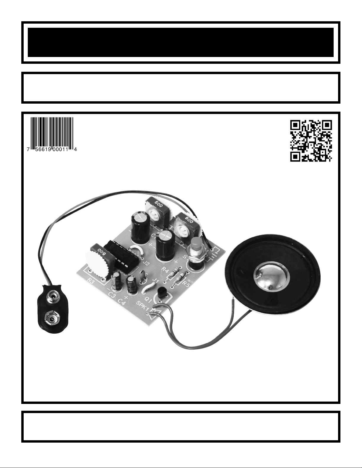
DIGITAL BIRD KIT
MODEL K-19
Assembly and Instruction Manual
Copyright © 2012, 1989 by Elenco®Electronics, Inc. All rights reserved. Revised 2012 REV-H 753219
No part of this book shall be reproduced by any means; electronic, photocopying, or otherwise without written permission from the publisher.
ELENCO
®
Page 2
PARTS LIST
If you are a student, and any parts are missing or damaged, please see instructor or bookstore. If you purchased
this Digital Bird Kit from a distributor, catalog, etc., please contact ELENCO
®
(address/phone/e-mail is at the
back of this manual) for additional assistance, if needed. DO NOT contact your place of purchase as they will
not be able to help you.
RESISTORS
Qty. Symbol Description Color Code Part #
r 1R5 39Ω 5% 1/2W orange-white-black-gold 123901
r 1R4 4.7kΩ 5% 1/4W yellow-violet-red-gold 144700
r 3 R1, R2, R3 500Ω Potentiometer 191351
CAPACITORS
Qty. Symbol Value Description Part #
r 1 C5 10pF (10) Discap 211011
r 2 C3, C4 1μF Electrolytic 261047
r 2 C1, C2 1000μF Electrolytic 291044
SEMICONDUCTORS
Qty. Symbol Value Description Part #
r 1 Q1 2N3904 Transistor 323904
r 1 IC1 4011 Integrated circuit (IC) 334011
MISCELLANEOUS
Qty. Symbol Description Part #
r 1 PC board 518019
r 1 S1 Switch push button 540001
r 1 B1 Battery snap 9V 590098
r 1 SPK1 Speaker 8Ω 590102
r 1 IC socket 14-pin 664014
r 2 Wire 4” blue 814620
-1-
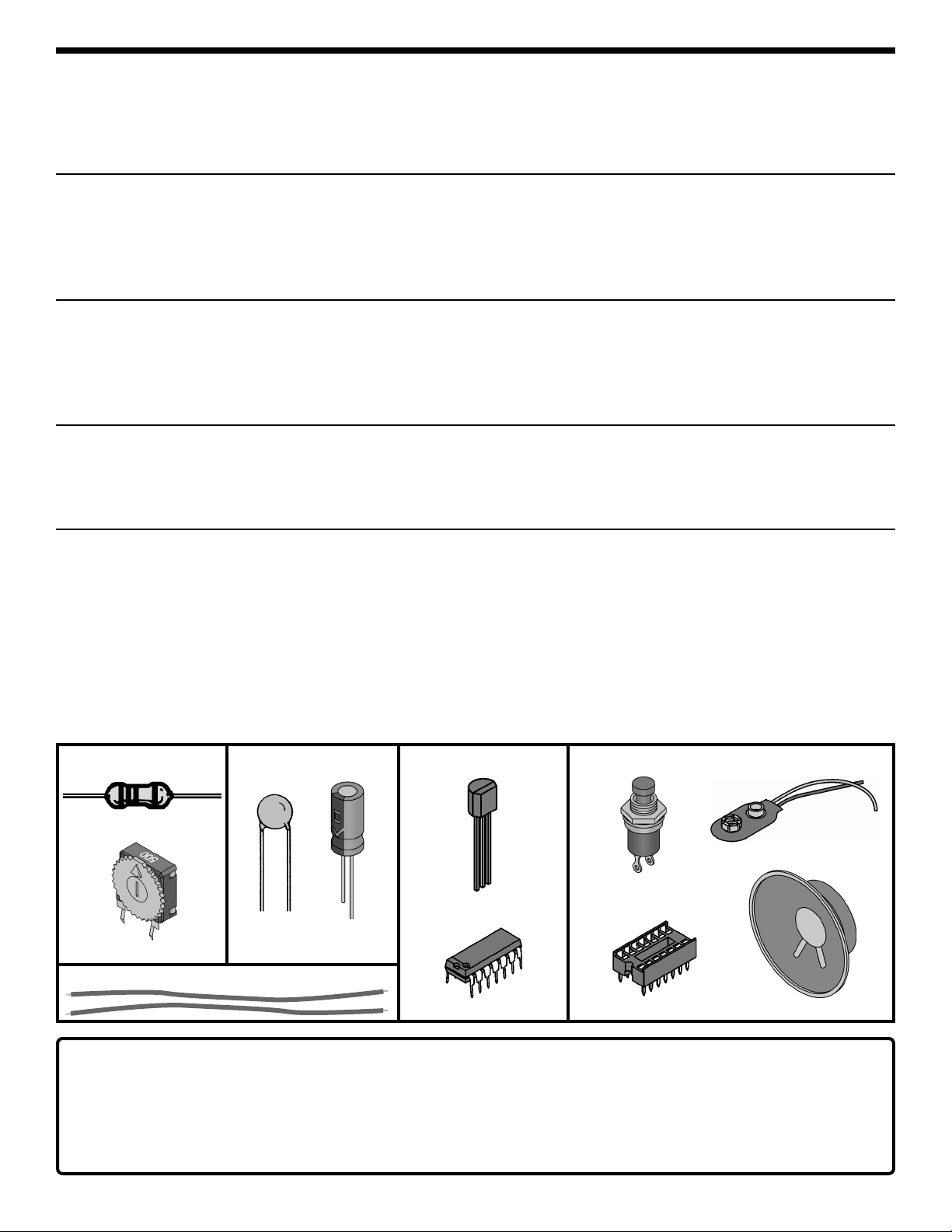
Resistors
PARTS IDENTIFICATION
• Do not short circuit the battery terminals.
• Never throw the battery in a fire or attempt to open its outer casing.
•
Use only 9V alkaline battery (not included).
• Insert battery with correct polarity.
• Non-rechargeable batteries should not be recharged.
Rechargeable batteries should only be charged under adult
supervision, and should not be recharged while in the product.
• Remove battery when it is used up.
•
Batteries are harmful if swallowed, so keep away from small children.
Batteries:
Push button switch with
1/4” nut and washer
Electrolytic
(radial)
Discap
Transistor
Carbon film
500Ω Potentiometer
Capacitors
Wire
Semiconductors
Integrated circuit (IC)
Miscellaneous
Battery snap 9V
Speaker 8Ω
IC socket 14-pin
Page 3
-2-
Warning:
If the capacitor is
connected with
incorrect polarity, it
may heat up and
either leak, or
cause the capacitor
to explode.
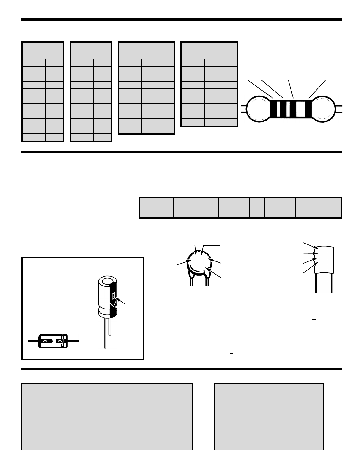
IDENTIFYING RESISTOR VALUES
Use the following information as a guide in properly identifying the value of resistors.
BANDS
METRIC UNITS AND CONVERSIONS
Abbreviation Means Multiply Unit By Or
p Pico .000000000001 10
-12
n nano .000000001 10
-9
μ micro .000001 10
-6
m milli .001 10
-3
– unit 1 10
0
k kilo 1,000 10
3
M mega 1,000,000 10
6
1. 1,000 pico units = 1 nano unit
2. 1,000 nano units = 1 micro unit
3. 1,000 micro units = 1 milli unit
4. 1,000 milli units = 1 unit
5. 1,000 units = 1 kilo unit
6. 1,000 kilo units = 1 mega unit
IDENTIFYING CAPACITOR VALUES
Capacitors will be identified by their capacitance value in pF (picofarads), nF (nanofarads), or μF (microfarads).
Most capacitors will have their actual value printed on them. Some capacitors may have their value printed in
the following manner. The maximum operating voltage may also be printed on the capacitor.
Electrolytic capacitors have a positive
and a negative electrode. The
negative lead is indicated on the
packaging by a stripe with minus
signs and possibly arrowheads. Also,
the negative lead of a radial
electrolytic is shorter than the positive
one.
Polarity
marking
BAND 1
1st Digit
Color Digit
Black 0
Brown
1
Red 2
Orange 3
Yellow 4
Green 5
Blue 6
Violet 7
Gray 8
White 9
BAND 2
2nd Digit
Color Digit
Black 0
Brown 1
Red 2
Orange 3
Yellow 4
Green 5
Blue 6
Violet 7
Gray 8
White 9
Multiplier
Color Multiplier
Black 1
Brown 10
Red 100
Orange 1,000
Yellow 10,000
Green 100,000
Blue 1,000,000
Silver 0.01
Gold 0.1
Resistance
Tolerance
Color Tolerance
Silver ±10%
Gold ±5%
Brown ±1%
Red ±2%
Orange ±3%
Green ±0.5%
Blue ±0.25%
Violet ±0.1%
1
2 Multiplier Tolerance
Multiplier
For the No. 0 1 2 3 4 5 8 9
Multiply By 1 10 100 1k 10k 100k .01 0.1
(+)
(–)
(+)
(–)
Axial
Radial
Second digit
First digit
Multiplier
Tolerance*
Note: The letter “R” may be used at times
to signify a decimal point; as in 3R3 = 3.3
The letter M indicates a tolerance of +20%
The letter K indicates a tolerance of +10%
The letter J indicates a tolerance of +5%
Maximum working voltage
(may or may not appear
on the cap)
The value is 10 x 10 =
100pF, +10%, 50V
*
CERAMIC DISC MYLAR
First digit
Second digit
Multiplier
Tolerance*
2A222J
100V
The value is 22 x 100 =
2,200pF or .0022μF, + 5%, 100V
101K
50V
Page 4

-3-
CIRCUIT OPERATION
The Digital Bird uses four digital NAND gates to
produce the birdy sounds. It consists of four
individual circuits: two oscillators, an audio amplifier
and an R/C network as shown in the block diagram
in Figure 1. The first oscillator produces a square
wave signal whose frequency can be varied by
adjusting a variable resistor. The output of the first
oscillator is modified by passing it through a high
pass R/C network. The resulting sound is fed to an
audio amplifier which drives a speaker.
What makes the Digital Bird so exciting is the fact
that three circuits have variable controls. Thus, the
sound output can be adjusted over a wide range to
give an unusually large variety of audio sounds in
the “birdy frequency” spectrum.
Oscillator Circuit
The circuit of the first oscillator is shown in Figure 2.
Two NAND gates are wired as inverters. This means
that when the input is high, the output goes low. To
make a circuit oscillate, we need positive feedback.
This is achieved by adding capacitor C1. The output
of inverter G1 is fed back to the input of G2 in the
same phase to build-up the oscillations. Capacitor
C1 and resistor R1 form an R/C network, and this
network determines the frequency of oscillation.
Since resistor R1 can be varied, the frequency of
oscillation can be varied. The resulting output
produces a square wave whose frequency is varied
by adjusting resistor R1. The operation of the
second oscillator is the same as the first oscillator
except that the value of capacitor C1 is 1,000 times
smaller. This produces a frequency much higher
than the first oscillator. The input of the second
oscillator is modulated with the output of the first
oscillator to produce the weird sounds of the Digital
Bird.
Audio Amplifier
Figure 3 shows the circuit of the audio amplifier
used in the Digital Bird. This transistor circuit is
known as an emitter follower. The output of the
second oscillator is fed to the input base of the
amplifier via capacitor C4. In a transistor, the baseemitter current is amplified in the collector-emitter
circuit, usually about 100 times. Therefore, the
speaker will produce a much amplified sound. The
emitter of transistor Q1 supplies the power to the
speaker. Resistor R5 is added to protect the
transistor from excessive current. Resistor R4 is
added to bias the transistor on.
The R/C Circuit
There is an R/C network in both of the oscillators in
the Digital Bird. These R/C circuits control the
frequency of oscillation. The output of the first
oscillator is a low frequency square wave. This
square wave is fed to a third R/C network which
drives the second oscillator. Resistor R2 and
capacitor C2 make up this R/C network. Its function
is to alter the square wave before it is mixed with the
second oscillator. The resulting special effects
voltages are fed to the audio amplifier stage through
coupling capacitor C4. The function is to block the
DC output of G3 while passing the desired AC
pulse.
Note that the waveform of each of the three circuits,
the two oscillators and the connecting R/C circuit,
can be altered by varying potentiometer R1, R2,
and R3. The results are the interesting special effect
sounds which provide hours of entertainment.
First
oscillator
variable
RC circuit
Second
oscillator
variable
Audio amp
SPK
Figure 1
LO
R1
Positive feedback
G2
G1
LO
HI
C1
Output
Figure 2
SPK
Q1
C5
C4
R4
R5
9V
Figure 3
Page 5

-4-
CONSTRUCTION
Solder
Soldering Iron
Foil
Solder
Soldering Iron
Foil
Component Lead
Soldering Iron
Circuit Board
Foil
Rosin
Soldering iron positioned
incorrectly.
Solder
Gap
Component Lead
Solder
Soldering Iron
Drag
Foil
1. Solder all components from the
copper foil side only. Push the
soldering iron tip against both the
lead and the circuit board foil.
2. Apply a small amount of solder to
the iron tip. This allows the heat to
leave the iron and onto the foil.
Immediately apply solder to the
opposite side of the connection,
away from the iron. Allow the
heated component and the circuit
foil to melt the solder.
1. Insufficient heat - the solder will
not flow onto the lead as shown.
3. Allow the solder to flow around
the connection. Then, remove
the solder and the iron and let the
connection cool. The solder
should have flowed smoothly and
not lump around the wire lead.
4.
Here is what a good solder
connection looks like.
2. Insufficient solder - let the
solder flow over the connection
until it is covered.
Use just enough solder to cover
the connection.
3. Excessive solder - could make
connections that you did not
intend to between adjacent foil
areas or terminals.
4. Solder bridges - occur when
solder runs between circuit paths
and creates a short circuit. This is
usually caused by using too much
solder.
To correct this, simply drag your
soldering iron across the solder
bridge as shown.
What Good Soldering Looks Like
A good solder connection should be bright, shiny, smooth, and uniformly
flowed over all surfaces.
Types of Poor Soldering Connections
Introduction
The most important factor in assembling your K-19 Digital Bird Kit is
good soldering techniques. Using the proper soldering iron is of prime
importance. A small pencil type soldering iron of 25 watts is
recommended. The tip of the iron must be kept clean at all times and
well-tinned.
Solder
For many years leaded solder was the most common type of solder
used by the electronics industry, but it is now being replaced by leadfree solder for health reasons. This kit contains lead-free solder, which
contains 99.3% tin, 0.7% copper, and has a rosin-flux core.
Lead-free solder is different from lead solder: It has a higher melting
point than lead solder, so you need higher temperature for the solder to
flow properly. Recommended tip temperature is approximately 700
O
F;
higher temperatures improve solder flow but accelerate tip decay. An
increase in soldering time may be required to achieve good results.
Soldering iron tips wear out faster since lead-free solders are more
corrosive and the higher soldering temperatures accelerate corrosion,
so proper tip care is important. The solder joint finish will look slightly
duller with lead-free solders.
Use these procedures to increase the life of your soldering iron tip when
using lead-free solder:
• Keep the iron tinned at all times.
• Use the correct tip size for best heat transfer. The conical tip is the
most commonly used.
• Turn off iron when not in use or reduce temperature setting when
using a soldering station.
•
Tips should be cleaned frequently to remove oxidation before it becomes
impossible to remove. Use Dry Tip Cleaner (Elenco
®
#SH-1025) or Tip
Cleaner (Elenco®#TTC1). If you use a sponge to clean your tip, then use
distilled water (tap water has impurities that accelerate corrosion).
Safety Procedures
• Always wear safety glasses or safety goggles to
protect your eyes when working with tools or
soldering iron, and during all phases of testing.
• Be sure there is adequate ventilation when soldering.
•
Locate soldering iron in an area where you do not have to go around
it or reach over it. Keep it in a safe area away from the reach of
children.
• Do not hold solder in your mouth. Solder is a toxic substance.
Wash hands thoroughly after handling solder.
Assemble Components
In all of the following assembly steps, the components must be installed
on the top side of the PC board unless otherwise indicated. The top
legend shows where each component goes. The leads pass through the
corresponding holes in the board and are soldered on the foil side.
Use only rosin core solder.
DO NOT USE ACID CORE SOLDER!
'
Page 6

-5-
ASSEMBLE COMPONENTS TO THE PC BOARD
Figure D
Mount the transistors with
the flat side in the same
direction as marked on the
PC board. Solder and cut
off the excess leads.
Figure B
Use an excess lead to form a jumper wire. Bend the wire to the correct length
and mount it to the PC board.
R2 - 500Ω Potentiometer
R1 - 500Ω Potentiometer
C2 - 1000μF Electrolytic Cap.
(see Figure A)
C1 - 1000μF Electrolytic Cap.
(see Figure A)
R4 - 4.7kΩ 5% 1/4W Resistor
(yellow-violet-red-gold)
J2 - Jumper Wire
(see Figure B)
IC1 - 14-pin IC Socket
IC1 - 4011 Integrated Circuit
(see Figure C)
C5 - 10pF Discap
R3 - 500Ω Potentiometer
C3 - 1μF Electrolytic Capacitor
(see Figure A)
C4 - 1μF Electrolytic Capacitor
(see Figure A)
J1 - Jumper Wire
(see Figure B)
B1 - Battery Snap -
Install the red
wire into the positive (+) hole and the
black wire into the negative (–) hole.
Solder and cut off the excess leads.
S1 - Push Button Switch
R5 - 39Ω 5% 1/2W Resistor
(orange-white-black-gold)
Q1 - 2N3904 Transistor
(see Figure D)
SPK1 - Speaker
Cut two 4” wires and strip 1/8” of insulation
off of both ends. Solder a wire to each lug
of the speaker and then insert the other
end of the wires through the hole in the PC
board as shown. Solder the wires in the
position shown on the top legend. Cut off
the excess leads.
Red
Black
Flat
1/8”
Figure C
Insert the IC socket into the PC board with the
notch in the direction shown on the top legend.
Solder the IC socket into place. Insert the IC
into the socket with the notch in the same
direction as the notch on the socket.
Figure A
Electrolytic capacitors have polarity.
Be sure to mount them with the
short negative (–) lead (marked on
side) in the correct hole. The PC
board is marked to show the lead
positioning.
Warning:
If the capacitor is connected with
incorrect polarity, it may heat up
and either leak, or cause the
capacitor to explode.
Polarity
marking
(–)
(+)
Notch
IC
Socket
PC board
Page 7

-6-
OPERATION
Foil Side of PC Board
Install a 9-volt battery to the battery snap (B1).
Adjust the potentiometer R1 so that the arrow is
turned all of the way counter-clockwise. Adjust the
potentiometers R2 and R3 so that the arrow is
turned all of the way clockwise. Hold down the push
button switch and the bird will sing. For varied
sounds, adjust the potentiometers. Be creative, a
variety of sounds can be created!
1. One of the most frequently occurring problems is
poor solder connections.
a) Tug slightly on all parts to make sure that
they are indeed soldered.
b) All solder connections should be shiny.
Resolder any that are not.
c) Solder should flow into a smooth puddle
rather than a round ball. Resolder any
connection that has formed into a ball.
d) Have any solder bridges formed? A solder
bridge may occur if you accidentally touch
an adjacent foil by using too much solder or
by dragging the soldering iron across
adjacent foils. Break the bridge with your
soldering iron.
2. Be sure that all components have been mounted
in their correct places.
a) Make sure that C1-C4, the electrolytic
capacitors, are mounted correctly. The
negative lead should be in the hole as
shown on the top legend.
b) Make sure that U1 has been installed
correctly. The notch of the IC is in the same
direction as the notch on the socket.
c) Pay close attention to the red and black
wires of the battery snap. The red wire
should be installed in the positive (+) hole
and the black wire in the negative (–) hole.
Snap in a fresh 9-volt battery.
TROUBLESHOOTING
Contact ELENCO®if you have any problems. DO NOT contact your place of purchase as they will not be able
to help you.
SCHEMATIC DIAGRAM
Page 8

ELENCO
®
150 Carpenter Avenue
Wheeling, IL 60090
(847) 541-3800
Website: www.elenco.com
e-mail: elenco@elenco.com
QUIZ
1. The Digital Bird uses four ____________________ to produce the birdy sounds.
2. There are _________ oscillators used in the Digital Bird.
3. The frequency of the oscillators are controlled by ________ circuits.
4. The frequency of the first oscillator is lower because the capacitor is ___________ than the value used in
the second oscillator.
5. The NAND gates are wired as ______________.
6. An IC inverter, if the input is high, then the output will be _________________.
7. To vary the frequency of the second oscillator, you must vary resistor _________.
8. The main component of the audio amplifier is the ________________.
9. The speaker gets its power from the _______________ of transistor Q1.
10. There are _____________ variable resistor(s) in the Digital Bird.
Answers: 1. NAND gates; 2. two; 3. R/C; 4. larger; 5. inverters; 6. low; 7. R2; 8. transistor; 9. emitter; 10. three
 Loading...