


Xi-A Series Loudspeaker System
Flying Manual
ELECTRO-VOICE® Xi-A Rigging Manual

Table of Contents |
|
|
0. Rigging-Safety Warning .......................................................................................................................................... |
2 |
|
I. Introduction ......................................................................................................................................................... |
3 |
|
1.1 |
The Flying Xi-A Loudspeaker Systems .................................................................................................... |
3 |
II. Basic Xi-A Rigging Primer ....................................................................................................................................... |
3 |
|
2.1 Anatomy of an Xi-A Flying System ........................................................................................................... |
3 |
|
2.2 |
The Rigging Hardware ............................................................................................................................. |
4 |
2.3 |
The Xi-A Flying Concept .......................................................................................................................... |
7 |
|
2.3.1 Accoustical Considerations ...................................................................................................... |
7 |
|
2.3.2 Practical Considerations .......................................................................................................... |
8 |
III. Associated Rigging Hardware for Flying Xi-A Loudspeaker Systems .................................................................. |
10 |
|
3.1 |
Grids and Associated Rigging Hardware ............................................................................................... |
10 |
IV. Strength Ratings, Safety Factors, and Special Safety Considerations ................................................................. |
10 |
|
4.1 |
Strength Ratings and Safety Factors ..................................................................................................... |
10 |
4.2 |
Special Safety Considerations for Xi-A Loudspeaker Arrays .................................................................. |
12 |
4.3 |
Special Safety Considerations for Rigging Strap Assemblies ................................................................. |
14 |
|
4.3.1 Redundant Attachment Points ................................................................................................ |
14 |
|
4.3.2 Special Considerations for Polyester Webbing....................................................................... |
14 |
4.4 |
Special Safety Considerations for Grid & Building Structural Supports .................................................. |
14 |
V. Rigging Inspection and Precautions ..................................................................................................................... |
15 |
|
5.1 |
Xi-A System Components ...................................................................................................................... |
15 |
|
5.1.1 Xi-A Loudspeaker Systems .................................................................................................... |
15 |
|
5.1.2 Rigging Strap Assemblies ...................................................................................................... |
15 |
5.2 Associated Hardware ............................................................................................................................. |
15 |
|
|
5.2.1 Grid Assembly ........................................................................................................................ |
15 |
|
5.2.2 Chain Hoists........................................................................................................................... |
15 |
|
5.2.3 Building Structural Supports ................................................................................................... |
15 |
|
5.2.4 Mechanical Components ........................................................................................................ |
16 |
VI. Appendices ....................................................................................................................................................... |
17 |
|
Appendix A Xi-A Rigging Accessories ........................................................................................................ |
17 |
|
Appendix B References ............................................................................................................................. |
17 |
|
|
B.1 Accoustical References ............................................................................................................ |
17 |
|
B.2 Mechanical References ............................................................................................................ |
18 |
1 |
ELECTRO-VOICE® Xi-A Rigging Manual |

0. Rigging-Safety Warning
This document details general rigging practices appropriate to the entertainment industry, as they would apply to the rigging of Electro-Voice Xi-A loudspeaker systems. It is intended to familiarize the reader with standard rigging hardware and techniques for suspending Xi-A loudspeaker systems overhead. Only persons with the knowledge of proper hardware and safe rigging techniques should attempt to suspend any sound systems overhead. Prior to suspending any
Electro-Voice Xi-A loudspeaker systems overhead, it is essential that the user be familiar with the strength ratings, rigging techniques and special safety considerations outlined in this manual. The rigging techniques and practices recommended in this manual are, of necessity, in general terms to accommodate the many variations in loudspeaker arrays and rigging configurations. As such, the user is expressly responsible for the safety of all specific Xi-A loudspeaker array designs and rigging configurations as implemented in practice.
All the general rigging material contained in this manual is based on the best available engineering information concerning materials and practices, as commonly recognized in the United States, and is believed to be accurate at the time of the original printing. As such, the information may not be directly applicable in other countries. Furthermore, the regulations and requirements governing rigging hardware and practices may be superseded by local regulations. It is the responsibility of the user to ensure that any Electro-Voice loudspeaker system is suspended overhead in accordance with all current federal, state and local regulations.
All specific material concerning the strength ratings, rigging techniques and safety considerations for the Xi-A loudspeaker systems is based on the best available engineering information concerning the use and limitations of the products. Electro-Voice continually engages in testing, research and development of its loudspeaker products. As a result, the specifications are subject to change without notice. It is the responsibility of the user to ensure that any Electro-Voice loudspeaker system is suspended overhead in accordance with the strength ratings, rigging techniques and safety considerations given in this document and any manual update notices. All non-Electro-Voice associated hardware items necessary to rig a complete Xi-A loudspeaker array (grids, chain hoists, building or tower supports and miscellaneous mechanical components) are the responsibility of others.
Electro-Voice
June, 2004
The exclamation point within an equilateral triangle is intended to alert the user to the presence of important operating and maintenance (servicing) instructions in the literature accompanying the appliance.
ELECTRO-VOICE® Xi-A Rigging Manual |
2 |

I. Introduction
1.1 The Flying Xi-A Loudspeaker Systems
The flying versions of the X-Array Install™ loudspeaker systems all incorporate a unique two-point flying system that consists of two lengths of heavy-duty, L-track, aircraft-type rigging hardware on the top and bottom of each enclosure. The design allows arrays to be assembled very quickly, and offers such flexibility in the vertical angling of the cabinets that pull-up points are usually unnecessary. Furthermore, the cabinets may be oriented with the rigging track on the top and bottom of the enclosure or on the sides of the enclosure. For fire safety and additional structural strength in both flying orientations, top-to-bottom and side-to-side metal straps link the rigging track assemblies inside the enclosure. In addition, a line of flying hardware accessories is available for use with the Xi-A loudspeaker systems from Sound Manufacturing, Inc. (See
Appendix A for available rigging accessories.)
II. Basic Xi-A Rigging Primer
2.1 Anatomy of an Xi-A Flying System
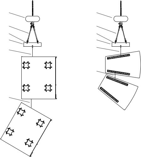
A basic two-cabinet flying system is shown in Figure 2.1a, illustrating the integral components that make up a typical Xi-A loudspeaker array, where the enclosures are oriented with the rigging hardware on the top and bottom of the enclosures. A similar two cabinet system is shown in Figure 2.1b where the enclosures are oriented with the rigging hardware on the sides of the enclosures. The top cabinets are the starting points for constructing the arrays in both examples.
These cabinets are first secured to a grid through the use of two grid straps per cabinet. (The GS-1B grid straps are recommended.) The Xi-A enclosures are equipped with two pieces of track, which have multiple positions where the grid straps may be attached. The linear positioning of the attachment points along the track (front-to-back) determines the vertical angling of the enclosure. The remaining ends of the grid straps are then secured to cross members of a grid. The relative positioning of the straps along the cross members of the grid (front to back) determine the relative horizontal splay angle between two adjacent columns of enclosures. A second row of enclosures may be added below the original two by utilizing linking straps that attach from the lower track pieces of the top enclosures to the upper track pieces of the bottom enclosures. (LS-1B, LS-2B and LS-3B linking straps, each a different length, are recommended.) Additional cabinets may be hung in succession in this fashion, as long as the load on any of the enclosures or rigging straps does not exceed their working-load-limit rating. The loudspeaker/array/grid assembly is then raised into position by a motorized chain hoist (or hoists) of sufficient load rating. Note that the weight of such an array can be quite substantial and the building structural supports to which the hoists are attached must be capable of supporting such a load with a sufficient safety factor. In permanent installations, the chain hoists are often eliminated, with the grid assembly being secured directly to the building structure. The reader is referred to Chapters IV and V of this manual for a detailed discussion of the structural strength ratings of the Xi-A loudspeakers and L- track rigging accessories, and information on how to safely suspend Xi-A loudspeaker systems overhead.
3 |
ELECTRO-VOICE® Xi-A Rigging Manual |
2.2 The Rigging Hardware
The Xi-A flying system utilizes the highest-tech aircraft-type hardware available for securing heavy loads. Four pieces of heavy-duty, aircraft-type, “L-Track” rigging hardware, specially machined extrusions of very-high-strength, aluminum-alloy material, are mounted in each enclosure. The track pieces are secured to high-strength, aluminum-alloy brackets that are an integral part of the Xi-A flying enclosure. Enclosure dimensions and rigging track locations are shown in Figure 2.2 for all of the Xi-A loudspeaker systems. For attachment to the track, the GS-1B grid-strap assembly, the LS-1B, LS-2B and LS-3B linking strap assemblies, the RS-1B double-stud, swivel-ring fitting assembly and the RS-2B single-stud, swivel-ring fitting assembly are available from Sound Manufacturing, Inc. (See Appendix A for details.) These assemblies, shown in Figure 2.3, have been specifically designed for optimal implementation of the Electro-Voice L-track flying systems. The GS-1B includes a double-stud, swivel-ring fitting on one end for attachment to the enclosure and a safety hook on the other end. The safety hook may be attached to 5/8-inch shackles, or may be secured directly to the grid through a 7/8-inch diameter hole in the grid bar-stock material. The LS-1B, LS-2B and LS-3B have double-stud swivel-ring fillings on both ends for linking two Xi- A enclosures together. The GS-1B, LS-1B and LS-2B rigging straps utilize polyester webbing strap material. Polyester webbing was chosen for its tremendous strength and because of its dynamic flexing capabilities. The force from any sudden jolt or shift in the load is absorbed by the strap rather than transmitted directly to the loudspeaker enclosure. In addition, polyester webbing is a flexible material that is easy to handle.
Hoist Motor |
Hoist Motor |
Wire Rope Sling |
Wire Rope Sling |
5/8” Shackle |
5/8” Shackle |
Grid |
Grid |
GS-1B |
GS-1B |
|
LS-1B
LS-3B
Figure 2.1a: Rigging Hardware on the |
Figure 2.1b: Rigging Hardware on the |
Top and Bottom of the Enclosures |
Sides of the Enclosures |
ELECTRO-VOICE® Xi-A Rigging Manual |
4 |

|
|
|
|
|
|
|
|
|
Notes: |
All Linear Dimensions in Inches All Angles in Degrees |
All Weights in Pounds Rigging Attachment Points Every 1.0 Inches Along Track |
Front & Rear Rigging Locations Shown for Double-Stud Fittings Single-Stud Fitting Locations Shifted Linearly +/-0.5 Inches |
Rigging Location, and Center of Gravity |
|
|
|
|
Enclosure Dimensions |
|
Center of |
Rigging Track |
|
Weight, |
||||||
|
|
|
|
|
|
|||||||||
|
|
|
|
Gravity |
|
|
||||||||
|
|
|
|
|
|
|
|
|
|
|
|
|||
|
|
Dim |
Dim |
Dim |
Dim |
Dim |
Dim |
Dim |
Dim |
Dim |
Dim |
Weight |
|
|
|
|
"A" |
"B" |
"C" |
"D" |
"E" |
"F" |
"G" |
"H" |
"I" |
"J" |
|
||
Type |
System |
|
Dimensions, |
|||||||||||
Total |
Total |
Side |
Front |
Rear |
Trap. |
From |
From |
Rear |
Front |
|
||||
|
|
|
||||||||||||
|
|
|
|
|||||||||||
|
|
Height |
Depth |
Depth |
Width |
Width |
Angle |
Bottom |
Back |
Point |
Point |
|
|
|
2-Way Small Enclosure |
Xi-1122A/64F |
23.000 |
14.043 |
13.234 |
14.936 |
7.844 |
15° |
11.625 |
7.475 |
2.544 |
8.544 |
59 |
|
|
2-Way Small/Med. Enclosure |
Xi-1152A/64F |
29.875 |
16.281 |
15.210 |
17.901 |
9.750 |
15° |
13.875 |
7.875 |
2.544 |
9.544 |
80 |
|
|
2-Way Small/Med. Enclosure |
Xi-1152A/94F |
29.875 |
16.281 |
15.210 |
17.901 |
9.750 |
15° |
13.875 |
7.875 |
2.544 |
9.544 |
80 |
|
|
3-Way Medium Enclosure |
Xi-1123A/106F |
31.541 |
18.636 |
17.573 |
18.046 |
12.480 |
9° |
16.063 |
8.125 |
2.806 |
10.806 |
115 |
|
|
3-Way Medium Enclosure |
Xi-2123A/106F |
39.653 |
18.636 |
17.573 |
18.046 |
12.480 |
9° |
20.063 |
8.125 |
2.806 |
10.806 |
140 |
Xi-A |
|
3-Way Large Enclosure |
Xi-1153A/64F |
36.000 |
29.875 |
28.867 |
23.072 |
13.928 |
9° |
17.969 |
14.815 |
2.806 |
18.806 |
195 |
||
3-Way Large Enclosure |
Xi-1183A/64F |
36.000 |
29.875 |
28.867 |
23.072 |
13.928 |
9° |
17.969 |
14.815 |
2.806 |
18.806 |
195 |
||
3-Way Extra-Large Enclosure |
Xi-2153A/64F |
48.539 |
29.875 |
28.867 |
23.072 |
13.928 |
9° |
24.270 |
15.438 |
2.806 |
18.806 |
240 |
2.2: |
|
|
||||||||||||||
Subwoofer, Non-Flying |
Xi-1191A |
36.000 |
29.875 |
28.867 |
23.072 |
13.928 |
9° |
16.813 |
16.081 |
N/A |
N/A |
150 |
|
|
Subwoofer, Flying |
Xi-1191AF |
36.000 |
29.875 |
28.867 |
23.072 |
13.928 |
9° |
16.813 |
16.081 |
2.806 |
18.806 |
150 |
Figure |
|
Bass Box, Non-Flying |
Xi-2181A |
36.000 |
29.875 |
28.867 |
23.072 |
13.928 |
9° |
18.000 |
16.125 |
N/A |
N/A |
184 |
||
|
||||||||||||||
Bass Box, Flying |
Xi-2181AF |
36.000 |
29.875 |
28.867 |
23.072 |
13.928 |
9° |
18.000 |
16.125 |
2.806 |
18.806 |
184 |
|
|
2-Way Mid-High Long-Throw |
Xi-2122MHA/42F |
36.000 |
29.875 |
28.867 |
23.072 |
13.928 |
9° |
18.000 |
13.875 |
2.806 |
18.806 |
190 |
|
|
2-Way Mid-High Half-Height |
Xi-1122MHA/64F |
23.462 |
29.875 |
28.867 |
23.072 |
13.928 |
9° |
11.313 |
14.500 |
2.806 |
18.806 |
136 |
|
|
ELECTRO-VOICE® Xi-A Rigging Manual
5
 Loading...