


Sys tems |
VariplexTM-XL
3-Way Screen System
· THX® approved*
· Patented high-frequency system · Vari-Intense Technology for
smooth, even coverage
· Compact design for use in large to small rooms
· Ring Mode Decoupling(RMDTM) provides greater Intelligiblity
· Digital Dynamics CapableTM
· Factory pre-assembled mid/high unit
Description
The Electro-Voice VariplexTM-XL is designed specifically for use in ultra-high-fi- delity cinema applications. The system is THX® approved* and offers Electro-Voice patented technologies. The VariplexTM-XL is a full three-way configuration that addresses many performance issues not addressed in other three-way designs. The VariplexTM-XL employs ElectroVoice’s patented 2 Vari Intense- (VI) variable-intensity low distortion horn system. This design offers two fundamental advantages. The variable horn throat impedance provides uniform sound pressure levels over the entire auditorium. Conventional horn systems attempt to do the same by aiming the center of the high-frequency/ mid-frequency horn toward the rear of the room. This conventional approach wastes fully one-half of the system energy and headroom, and radiates that wasted energy onto the ceiling and walls, thus producing reflections that further degrade overall intelligibility and system clarity. The patented variableintensity approach, on the other hand, compensates for the natural phenomenon of
sound reduction with distance and produces
______________________
1 THX is a registered trademake of Lucasfilm Ltd.
* The Variplex-XL is THX approved for, screen to last row distances, greater than 80 feet
2 U.S. Patent 5,020,630, Loudspeakers & Horn Therefor.
extremely uniform coverage for the entire seating area. The same level of fidelity in the front, middle and the back of the room is achieved while substantially reducing reflected energy and consequently greatly improving tonal quality and intelligibility. The advantages are twice the headroom and greatly improved fidelity.
The VariplexTM-XL is also unique in that its three-way design utilizes a bass/mid-bass/ high-frequency approach rather than a conventional bass mid-range/high-frequency design. This mid-bass/high-frequency approach produces superior vocal clarity. Also incorporated into the VariplexTM-XL is Electro-Voice’s RMD TM technology. RMDTM,or Ring Mode Decoupling, employees mechanical and acoustical equalization to resolve system resonances (or ringing modes) and frees electrical equalizers to perform the job they were originally intended to perform, that being room equalization and correction of the spectral characteristics inherent in the tranducers themselves. Prior designs have frequently attempted to "resolve” loudspeaker design issues with electrical equalizers. RMDTM substantially improves system transient detail and further
refines system clarity.
The unique performance enhancements and system capabilities are ideally suited to the high dynamic-range demands of digital material. When the pre-assembled HPK- VariplexTM-XL is used in conjunction with Electro-Voice’s THX ® approved subwoofers, the combination defines a new standard for realism and total system accuracy.
Low Frequency Assembly Instructions
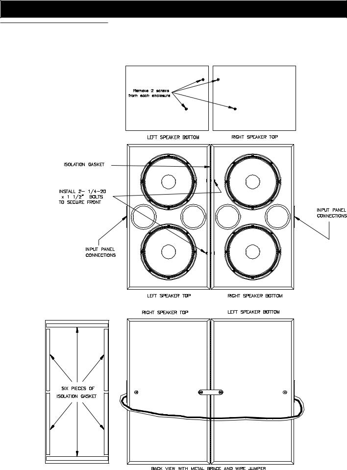
Refer to Figures l and 2 for the following The Low Frequency Unit comes shipped as two pieces (2-TL606MXL's).
1.Turn one of the low frequency units upside down and the other is right side up, arrange as illustrated in figure 1.
2.Remove the isolation gasket stips from the low frequency accesory bag (shipped with the HPK-VariplexTM-XL. Attach the strips to the up-side down speaker as shown in figure 1.
3.Remove the locking brace the low frequency acessory bag and attach it to the back of the unit right side up.
Variplex™-XL 3-Way Screen System
Figure 1—Low Frequency Speaker
Assembly
Variplex™ XL 3-Way Screen System

Variplex™-XL 3-Way Screen System
Figure 2—Low Frequency Wiring Configuration
4.Slide to two units together, with the backs almost touching and the front slightly appart. Engage the brace to the other speaker and tighten the bolt. Pull the front of the units together. Pass the 1/4-20 x 1 1/2 inch bolts through the holes opposite the T-nuts in each of the enclosures front baffle inside edge. (see figure 1) Tighten bolts unitl a 1/16 inch remains between the two enclosures.
5.Now that the Low frequency units are attached, the input panels can be connected. (See Figure 2 for referance) There are three wiring configurations possible. The speakers maybe wired in Series with one amp channel input or wired in Parallel with one amp channel input. Finally they may be wired seperately, each speaker on one amp channel. (NOTE: Use red jumper plugs but, do not us wire jumpers between J1 and J2 when using this particular configuration.)
Series wiring configuration: Connect J1 to J1 and J2 to J2, using supplied wire jumper.
Select the supplied white jumper plug and the yellow jumper plug. The white jumper plug is to be installed on the speaker which has T1 and T2 connected to the amplifier source. The yellow jumper is installed on the other speaker, for a nominal impedance of 12 ohms.
Parallel wiring configuration: Connect J1 to J1 and J2 to J2, using supplied wire jumper. Select the two supplied red jumper plugs and install one in each of the input panels.
The amplifier source may be connected to either input panel at T1 and T2, for a nominal impedance of 2.8 ohms.
Seperate wiring configuration: Do not con-
nect J1 to J1 amd J2 to J2. Select the two supplied red jumper plugs and install one in each of the input panels. The individual amplifier channels may be connected to each of the input panels at T1 and T2 for indivdual nominal impedances of 6 ohms.
System Screen Way-3 XL Variplex™
 Loading...