


Owner’s Manual
UCC 1 USB-CAN CONVERTER

I M P O R T A N T S A F E T Y I N S T R U C T I O N S
The lightning flash with arrowhead symbol, within an equilateral triangle is intended to alert the user to the 
 presence of uninsulated “dangerous voltage” within the
  product’s enclosure that may be of sufficient magnitude to constitute a risk of electric shock to persons.
The exclamation point within an equilateral triangle is intended to alert the user to the presence of important operating and maintance (servicing) instructions in the literature accompanying the appliance.
1.Read these instructions.
2.Keep these instructions.
3.Heed all warnings. 4.Follow all instructions.
5.Do not use this apparatus near water. Do not expose this apparatus to dripping or splahing and ensure that no objects filled with liquids, such as vases, are placed on this apparatus.
6.Clean only with a dry cloth.
7.Do not block any of the ventilation openings. Install in accordance with the manufactures instru ctions.
8.Do not install near any heat sources such as radiators, heat registers, stoves, or other apparatus (including amplifiers) that produce heat.
9.Only use attachments/accessories specified by the manufacturer.
10. Refer all servicing to qualified service personnel. Servicing is required when the apparatus has been damaged in any way, such as power-supply cord or plug is damaged, liquid has been spilled or objects have fallen into the apparatus,
For US and CANADA only:
Do not defeat the safety purpose of the grounding-type plug. A grounding type plug has two blades and a third grounding prong. The wide blade or the third prong are provided for your safety. When the provided plug does not fit into your outlet, consult an electrican for replacement of the absolete outlet.
I M P O R T A N T S E R V I C E I N S T R U C T I O N S
CAUTION: These servicing instructions are for use by qualified personnel only. To reduce the risk of electric shock, do not perform any servicing other than that contained in the Operating Instructions unless you are qualified to do so. Refer all servicing to qualified service personnel.
1. Security regulations as stated in the EN 60065 (VDE 0860 / IEC 65) and the CSA E65 - 94 have to be o beyed when servicing the appliance.
2. Use of a mains separator transformer is mandatory during maintenance while the appliance is opened, needs to be operated and is connected to the mains
3. Switch off the power before retrofitting any extensions, changing the mains voltage or the output voltage.
4. The minimum distance between parts carrying mains voltage and any accessible metal piece (metal enclosure), respectively between the mains poles has to be 3 mm and needs to be minded at all times.
The minimum distance between parts carrying mains voltage and any switches or breakers that are not connected to the mains (secondary parts) has to be 6 mm and needs to be minded at all times.
5. Replacing special components that are marked in the circuit diagram using the security symbol (Note) is only permissible when using original parts.
6. Altering the circuitry without prior consent or advice is not legitimate.
7. |
Any work security regulations that are applicable at the location where the appliance is being serviced have to be strictly |
|
|
obeyed. This applies also to any regulations about the work place itself. |
|
8. |
All instructions concerning the handling of MOS - circuits have to be observed. |
|
Note: |
S A F E T Y C O M P O N E N T ( H A S T O B E R E P L A C E D W I T H O R I G I N A L P A R T O N L Y ) |
|
Contents |
|
|
1. |
Description.................................................................................................................. |
17 |
2. |
Controls and Connections............................................................................................ |
18 |
3. |
Installation .................................................................................................................. |
19 |
3.1 |
Unpacking............................................................................................................... |
19 |
3.2 |
Rack-Mounting ....................................................................................................... |
19 |
4. |
Initial Operation .......................................................................................................... |
20 |
4.1 |
PC Connection and CAN Driver Installation............................................................ |
20 |
4.2 |
Installing IRIS ......................................................................................................... |
20 |
4.3 |
CAN-Bus Connection.............................................................................................. |
20 |
4.4 |
ISOLATED / GROUNDED Switch......................................................................... |
22 |
5. |
Monitor Bus ................................................................................................................ |
23 |
6. |
Technical Information ................................................................................................. |
23 |
6.1 |
The UCC1 USB-CAN Converter ............................................................................. |
23 |
6.2 |
The CAN-Bus Standard........................................................................................... |
24 |
6.3 |
Maximum Cable Length on the CAN-Bus ............................................................... |
25 |
7. |
Specifications.............................................................................................................. |
27 |
1.Description
The UCC1 USB-CAN CONVERTER is a bi-directional USB-to-CAN interface converter and is therefore the perfect solution for interconnecting Electro-Voice appliances with serial CAN-busses and PC or Notebook computers.
The UCC1 is a standalone unit with interface drivers for CAN and USB, audio monitoring output, USB and CAN controllers as well as microphone controllers for converting commands and data between PC and CAN-bus-units. The isolated CAN-bus interface reduces ground-loop interference noise to an absolute minimum. The UCC1 receives its operational power via USB from the connected PC, so that no external power supply unit is needed.
This owner’s manual illustrates installation and initial operation of the UCC1 when used together with Electro-Voice P-Series Remote Amplifiers. Please, carefully read and mind all instructions and precautions. Keep this owner’s manual at a save place for further reference.
Characteristics
∙Data rate up to 500 kbit/s
∙Galvanic separation of the CAN-bus, switchable
∙100 network devices possible
∙Monitor-bus in network cabling; output signal via XLR-type connector
∙Power supply via USB from the connected PC; separate power supply unit is not needed
17
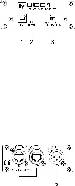
2.Controls and Connections
Fig. 1: UCC1 front panel
1.USB connector
This connector is for the connection to the USB-port on your PC. The interface complies with the USB 1.1 specifications and offers data transfer as well as operation voltage supply for the UCC1.
2.STATUS indicator
The STATUS LED indicates the actual operational state of the UCC1. The indicator lights when the UCC1 has been connected to the PC, the dedicated driver software has been installed, and the PC has recognized the unit. The LED blinks during data accesses.
3.CAN ISOLATED / GROUNDED switch
Setting this switch to ISOLATED galvanically isolates the CAN-port of the UCC1 from the rest of the circuitry, effectively eliminating ground-loop interference noise. Setting the switch to GROUNDED galvanically connects the CAN-bus to the USB-port ground and thus to the PC.
Fig 2: UCC1 rear view
4.CAN BUS IN / OUT connectors
These two sockets are for connecting EV-appliances that are furnished with serial CAN-bus. Both connectors are connected in parallel for convenient carrying through CAN-bus data.
5.MONITOR connector
The MONITOR connector provides audio signal output for the monitor bus of EV P-Series Remote Amps. The monitor bus allows listening to the audio signal of any amplifier within the system, without the need for additional wiring.
18
 Loading...