

Electrolux AOS062GTP1 Installation Manual
Lenghtwise oven
Touch Level
SERVICE MANUAL
Code: 0411400000
Issue: 1
Date: 25/05/2010
Service Manual
LENGHTWISE OVENS
TOUCH Level
CONTENTS:
PROJECT REF:
AUTHORS:
CONTRIBUTION BY:
DOCUMENT HISTORY:
This document contains the information about parameters that can be read
and/or modified by means of user interface, service utilities…
Oven range ONE lengthwise Touch level
M.Gerolami
S.Gant
F.Ornella
Rel. Date: File: Author: Note:
1 25/05/2010 - M.Gerolami
file: 0411400000 TOUCH service manual EN ©Copyright 2010 by Electrolux Professional
Issued by Customer Support Oven Platform
P.1/52

SERVICE MANUAL
Oven Lenghtwise – Touch Level Code: 0411400000
INDEX
1 IDENTIFICATION OF THE APPLIANCE (MODEL / SERIAL NUMBER).......................................... 4
1.1 P
RODUCT NUMBER CODE-
1.2 S
ERIAL NUMBER
..................................................................................................................... 4
PNC................................................................................................. 4
2 FUNCTIONAL SCHEME / WIRING CONNECTIONS POWER MAIN BOARD ................................... 5
3 FUNCTIONAL DIAGRAM / USER BOARD CONNECTIONS............................................................ 8
4 TOUCH SCREEN: MAIN WINDOW/ENVIRONMENT .................................................................. 10
4.1 M
4.2 D
4.3 D
4.4 M
4.5 I
4.6 A
AIN MENU
RAWER UTILITIES & INFORMATION BAR
RAWER COOKING UTILITIES
ESSAGE DIALOGS
NFORMATION AREA (WARNING, ALARMS AND UTILITY
DVANCED SERVICE AND PARAMETERS ENVIRONMENT
.......................................................................................................................... 11
.................................................................................. 12
.................................................................................................. 13
................................................................................................................. 14
)............................................................... 15
................................................................ 16
5 “SETTING” ENVIRONMENT ...................................................................................................... 17
5.1 L
EVEL 1: MAIN USER SETTINGS
5.2 L
EVEL 2:
5.3 L
EVEL 3 (ADVANCED):
USER
PARAMETERS
SERVICE
................................................................................................ 18
................................................................................................. 19
PARAMETERS
.......................................................................... 20
6 CYCLES, UTILITY E MAIN PARAMETERS .................................................................................... 21
7 “SERVICE UTILITIES” ENVIRONMNET........................................................................................ 23
7.1 C
OOKING PROGRAMS DOWNLOAD
7.2 U
PLOAD COOKING PROGRAMS FROM
7.3 U
PGRADE SOFTWARE TOUCH USER
7.4 A
DVANCED PROGRAMMING ENVIRONMENT
7.5 T
OUCH SCREEN TEST
.............................................................................................................. 29
............................................................................................ 24
USB.................................................................................. 25
........................................................................................... 26
................................................................................ 28
8 “DATA MONITOR” ENVIRONMENT ............................................................................................ 30
9 CALIBRATION ........................................................................................................................... 33
9.1 C
AVITY OFFSET CALIBRATION
.................................................................................................. 33
10 SOFTWARE E USER TOUCH AND MAIN POWER SPARE PART ..................................................... 34
10.1 S
10.2 M
10.3 U
file: 0411400000 TOUCH service manual EN ©Copyright 2010 by Electrolux Professional
Issued by Customer Support Oven Platform
OFTWARE USER UPGRADE
AIN POWER COMPONENT REPLACEMENT
SER TOUCH COMPONENT REPLACEMENT
................................................................................................... 34
............................................................................... 35
................................................................................ 36
P.2/52

SERVICE MANUAL
Oven Lenghtwise – Touch Level Code: 0411400000
11 GAS SYSTEM ............................................................................................................................. 37
11.1 M
11.2 S
11.3 O
11.4 U
11.5 F
AIN COMPONENTS
ETTINGS AND PARAMETER GAS BURNER ADJUSTEMENTS
FFSET CALIBRATION OF THE GAS VALVE
SE OF MANOMETER (FOR OFFSET PRESSURE MEASURE
UNCTIONAL DIAGRAM
............................................................................................................. 37
................................................................................ 39
......................................................................................................... 41
........................................................... 37
) ............................................................ 40
12 ELECTRIC OVEN: FUNCTIONAL CONTACTORS DIAGRAM............................................................ 42
13 BOILER FUNCTIONALITY / SUPPLY WATER CHARACTERISTICS ................................................ 44
13.1 W
ATER CHARACTERISTIC AND TREATMENT
............................................................................. 45
14 “CLEANING” ENVIRONMENT ..................................................................................................... 46
14.1 G
REEN UTILITIES
................................................................................................................. 47
15 LAMBDA PROBE FUNCTIONALITY AND HUMIDITY MEASURE.................................................... 48
15.1
BASE INFORMATIONS
15.2
LAMBDA PROBE
.......................................................................................................... 48
.................................................................................................................. 48
15.3 L
AMBDA PROBE CONNECTORS
............................................................................................... 49
16 ALARM AND WARNING CODES .................................................................................................. 50
16.1 A
16.2 W
LARM TABLE (THE ALARM STOPS THE OVEN
ARNING TABLE (THE WARNING DOESN’T STOP THE OVEN
) ......................................................................... 50
)....................................................... 51
17 ATTACCHED DOCUMENTS AND FILE ......................................................................................... 52
17.1 M
17.2 T
17.3 U
17.4 I
17.5 S
17.6 T
17.7 G
17.8 P
AIN TOUCH WINDOW AND ENVIRONMENT PRESENTATION
ECHNICAL BULLETIN: WATER CHARACTERISTICS
PGRADE SOFTWARE TOUCH INSTRUCTION
NSTALLATION SOFTWARE TOUCH IN A SPARE PART USER: INSTRUCTION
OFTWARE COMPATIBLE TABLE
OUCH USER SOFTWARE RELEASE
AS ADJUSTEMENTS AND PARAMETER
ARAMETERS LIST
............................................................................................................... 52
;............................................................................................ 52
;......................................................................................... 52
; ................................................................................... 52
; ................................................................... 52
;............................................................................ 52
; ...................................................... 52
;..................................... 52
file: 0411400000 TOUCH service manual EN ©Copyright 2010 by Electrolux Professional
Issued by Customer Support Oven Platform
P.3/52
SERVICE MANUAL
Oven Lenghtwise – Touch Level Code: 0411400000
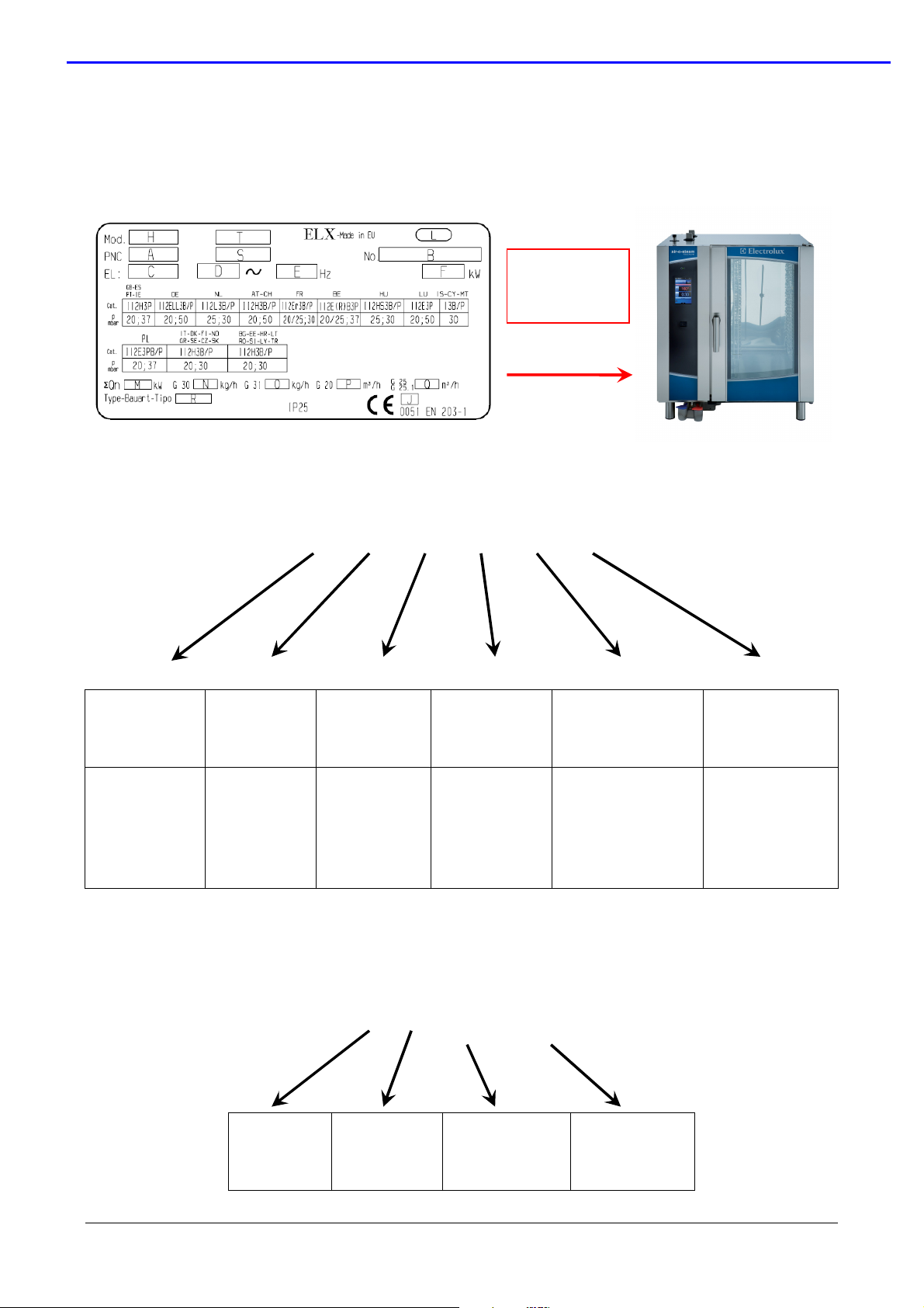
1 Identification of the appliance (model / serial number)
Each appliance is identified by a Product Number Code (PNC) and a serial number (see data
label in the left side of the oven).
BOTTOM PART
OF THE LEFT
SIDE OF THE
OVEN
1.1 Product Number Code- PNC
FACTORY
CODE
9F=Ovens Platf.
BRAND LEVEL VERSION MODEL
26=Electrolux
23=Zanussi
1.2 Serial Number
9F 2X 7 XX X
0= 6 GRIDS 1/1
7 = TOUCH
8 = LEVEL B
9 = LEVEL C
2X=ELECTRIC
7X=GAS
1= 6 GRIDS 2/1
2= 10 GRIDS 1/1
3= 10 GRIDS 2/1
4= 20 GRIDS 1/1
5= 20 GRIDS 2/1
s/n 0 xx 04 xxx
XX
STATUS
LEVEL
Bill of Material
product update
YEAR
0=2010
1=2011
WEEK
FACTORY
04: Ovens
PROGRESSIVE
NUMBER
file: 0411400000 TOUCH service manual EN ©Copyright 2010 by Electrolux Professional
Issued by Customer Support Oven Platform
P.4/52
SERVICE MANUAL
Oven Lenghtwise – Touch Level Code: 0411400000
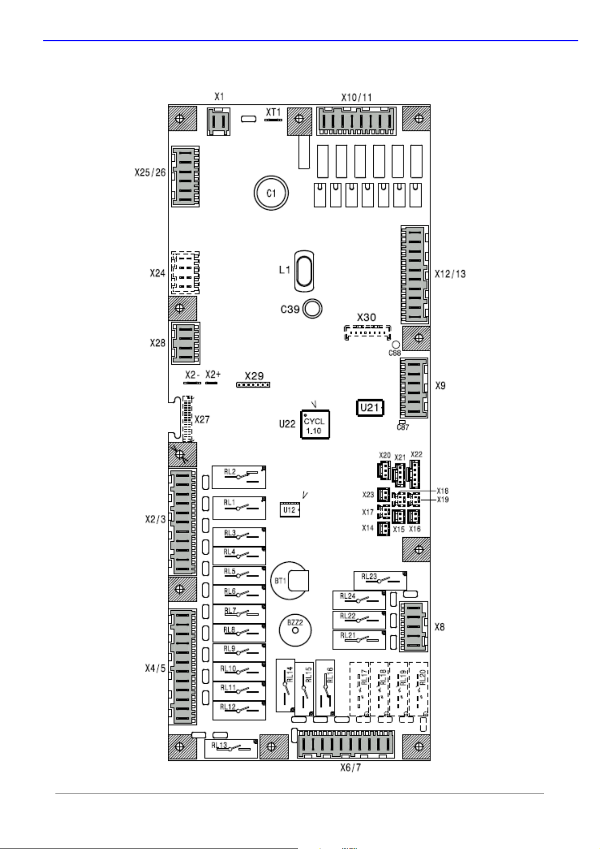
2 Functional scheme / wiring connections Power main board
file: 0411400000 TOUCH service manual EN ©Copyright 2010 by Electrolux Professional
Issued by Customer Support Oven Platform
P.5/52
SERVICE MANUAL
Oven Lenghtwise – Touch Level Code: 0411400000
CONNECTORS
DESCRIPTION
X1 supply voltage main power (24 Vac)
X2+ X2- supply voltage user Touch
X2/3 power supply cavity motors, cooling fans, cavity flap motor, switching
feeder lambda probe
X4/5 Power supply to coils of cavity/boiler heating element contactors or
cavity/boiler burner gas valves, steam condensing valve, humidifier valve,
cavity lamps
X6/7 Power supply to boiler water filling valves, boiler drain valve
X8 Power supply to cleaning system
X9 Output of PWM signal and 12 Vdc for burner fans
X10/11 High voltage digital input, i.e. thermal protection of the cavity fan motors
and command signal of the burner fans from the ignition devices
X12/13 Low voltage digital input, i.e. cleaning system water pressure switch, cavity
limiter, boiler limiter, door micro switch and micro switch of the cavity flap
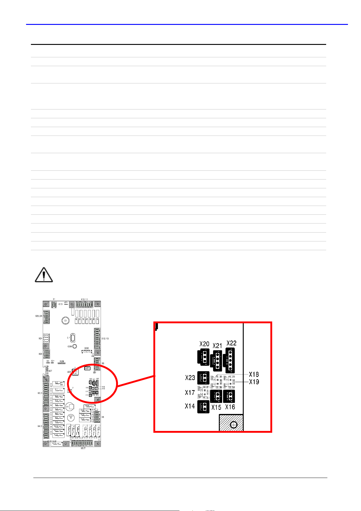
X14 Connection of bypass probe
X15 Connection of cavity probe
X16 Connection of boiler probe
X17 Connection of single point meat probe
X18 Connection of second cavity probe
X19 Connection of second boiler probe
X20, X21, X22 Connections of multi point probe
X23 Connection of lambda probe
X25/26 Connections of water level probes
X28 RS485 connection
For the probe connections not used (X17, X18, X19) use a jumper.
file: 0411400000 TOUCH service manual EN ©Copyright 2010 by Electrolux Professional
Issued by Customer Support Oven Platform
P.6/52

SERVICE MANUAL
Oven Lenghtwise – Touch Level Code: 0411400000
RELE’ DESCRIPTION
Touch Electric oven
RL 1/do1 FAN MOTOR POWER SUPPLY
RL 2/do2 HALF/FULL SPEED FAN MOTOR
RL 3/do3 COOLING FAN/S
RL 4/do4 SAFETY CONTACTOR (KS OR KS1&KS2) /LAMBDA FEEDER
RL 5/do5 N/A
RL 6/do6 CAVITY VENT VALVE
RL 7/do7 K2/K6 CONTACTOR/S (FOR CAVITY)
RL 8/do8 K4/K8 CONTACTOR/S (FOR BOILER)
RL 9/do9 K1/K5 CONTACTOR/S (FOR CAVITY)
RL 10/do10 K3/K7 CONTACTOR/S (FOR BOILER)
RL 11/do11 CAVITY UMIDIFIER SOLENOID VALVE
RL 12/do12 STEAM CONDENSER SOLENOID VALVE
RL 13/do13 CAVITY LAMPS
RL 14/do14 BOILER SLOW WATER FILLING
RL 15/do15 BOILER FAST WATER FILLING
RL 16/do16 BOILER AUTOMATIC DRAIN VALVE
RL 17/do17 N/A
RL 18/do18 N/A
RL 19/do19 N/A
RL 20 /do20 N/A
RL 21/do21 DETERGENT PUMP
RL 22/do22 RINSE PUMP
RL 23/do23 WATER SOLENOID VALVE (CLEANING SYSTEM)
RL 24/do24 N/A
Touch Gas oven
RL 1/do1 FAN MOTOR POWER SUPPLY
RL 2/do2 HALF/FULL SPEED FAN MOTOR
RL 3/do3 COOLING FAN/S
RL 4/do4 LAMBDA SWITCHING FEEDER
RL 5/do5 N/A
RL 6/do6 CAVITY VENT VALVE
RL 7/do7 CAVITY IGNITION DEVICE RESET
RL 8/do8 BOILER IGNITION DEVICE RESET
RL 9/do9 CAVITY IGNITION DEVICE POWER SUPPLY
RL 10/do10 BOILER IGNITION DEVICE POWER SUPPLY
RL 11/do11 CAVITY UMIDIFIER SOLENOID VALVE
RL 12/do12 STEAM CONDENSER SOLENOID VALVE
RL 13/do13 CAVITY LAMPS
RL 14/do14 BOILER SLOW WATER FILLING
RL 15/do15 BOILER FAST WATER FILLING
RL 16/do16 BOILER AUTOMATIC DRAIN VALVE
RL 17/do17 N/A
RL 18/do18 N/A
RL 19/do19 N/A
RL 20/do20 N/A
RL 21/do21 DETERGENT PUMP
RL 22/do22 RINSE PUMP
RL 23/do23 WATER SOLENOID VALVE (CLEANING SYSTEM)
RL 24/do24 N/A
file: 0411400000 TOUCH service manual EN ©Copyright 2010 by Electrolux Professional
Issued by Customer Support Oven Platform
P.7/52
SERVICE MANUAL
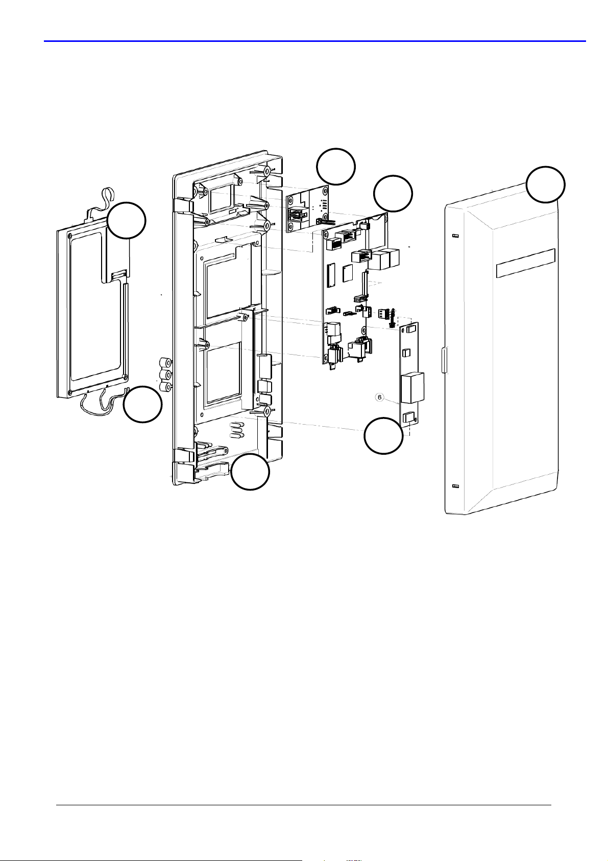
1
. Display LCD
;
1
2
3
4
5
6
7
Oven Lenghtwise – Touch Level Code: 0411400000
3 Functional diagram / user board connections
file: 0411400000 TOUCH service manual EN ©Copyright 2010 by Electrolux Professional
Issued by Customer Support Oven Platform
2. Thermoplastic protective box;
3. ON / OFF switch;
4. Electronic board;
5. Inverter for lamp;
6. Termoplastic protective cover;
7. Spacer / bumper to fix user in the control panel.
P.8/52
SERVICE MANUAL
Oven Lenghtwise – Touch Level Code: 0411400000
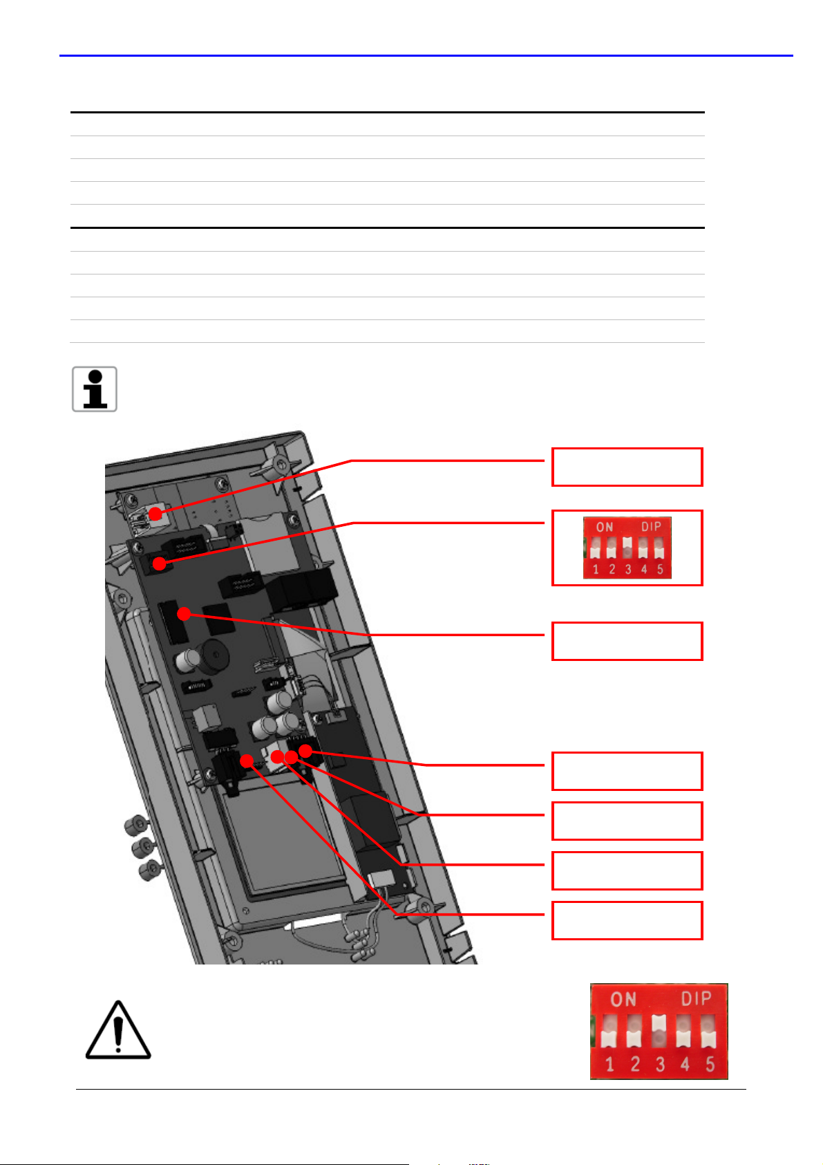
CONNECTORS DESCRIPTION
MAIN SWITCH Main power supply (24 Vac)
POWER SUPPLY
USB PORT
RS485 connections with main board
USB connections.
LED DESCRIPTION & status
LD1 SIGNAL LED, blinking.
LD2 Communication Led with main board, blinking
LD3 Communication Led with main board, blinking
LD7 Led, ON when the oven start
The blinking frequency of the LD2 e LD3 shows the status of the communication
between the electronic user and power.
DON’T CHANGE THE POSITION OF THE RED SWITCH DS1
IN THE TOUCH USER INTERFACE!
MAIN SWITCH
LD1 SIGNAL LED
POWER SUPPLY
LD2 e LD3
USB PORT
LD7
file: 0411400000 TOUCH service manual EN ©Copyright 2010 by Electrolux Professional
Issued by Customer Support Oven Platform
P.9/52
SERVICE MANUAL
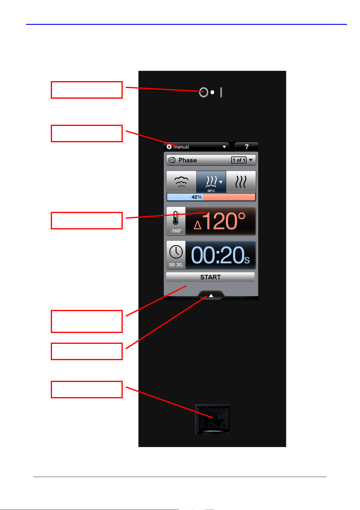
ON / OFF
button
MAIN MENU
INFORMATION BAR
ACTIV
E SCREEN
USB PORT
Oven Lenghtwise – Touch Level Code: 0411400000
4 Touch Screen: main window/environment
INFORMATION
AREA
file: 0411400000 TOUCH service manual EN ©Copyright 2010 by Electrolux Professional
Issued by Customer Support Oven Platform
P.10/52
SERVICE MANUAL
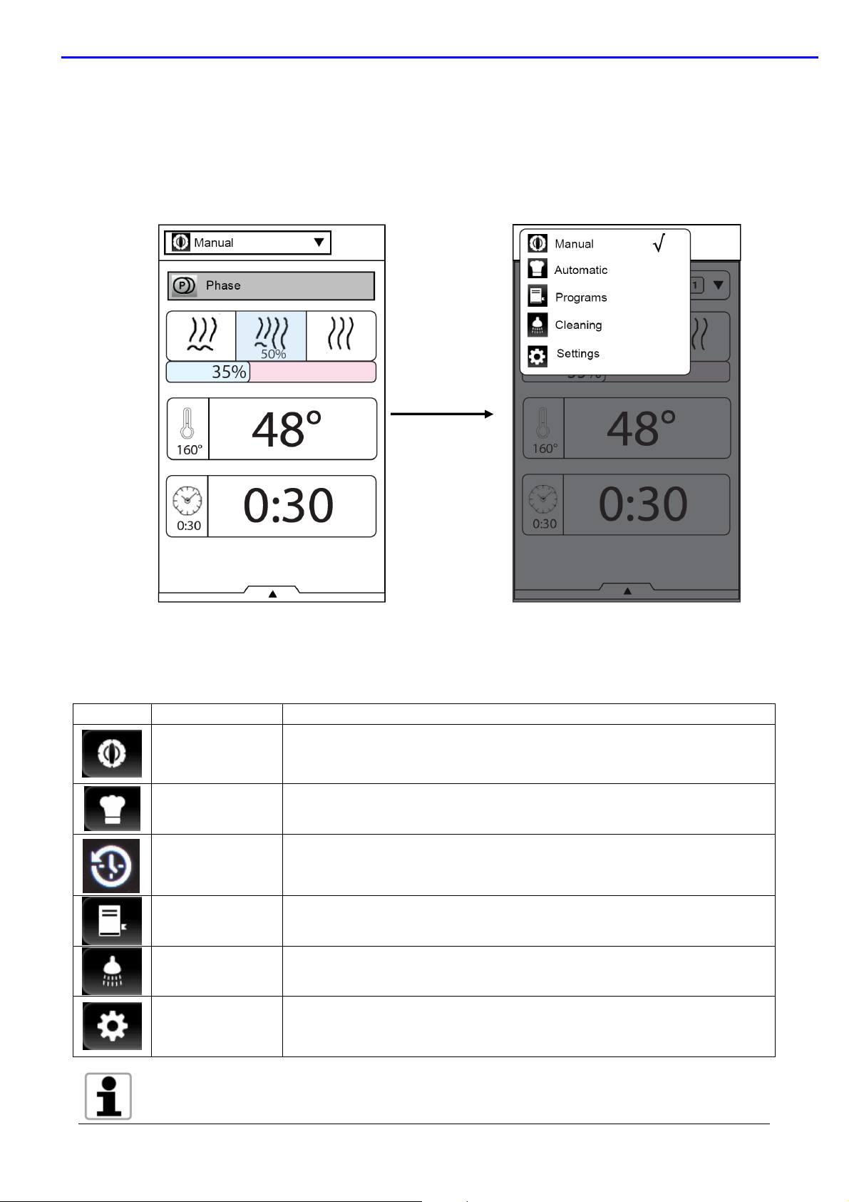
4.1 Main menu
The main menu is almost visible and active at the top of the screen (not during a cooking or
cleaning cycle). The active screen is highlighted with the mark √
Oven Lenghtwise – Touch Level Code: 0411400000
Press the corresponding icon to switch to a new work environment.
MAIN MENU: SELECTION LIST
ICON
NAME DESCRIPTION
Manual Manual cooking screen
Automatic Automatic cooking screen
Environment with data about status of the oven (service
Data Monitor
Programs Programs cooking cycle screen (saved by customer)
Cleaning Cleaning cycle and green function screen
function)
Visible when the parameter DATM nr97 is set a 1
Setting Setting parameter and “service” utilities
For the manual, automatic and programs cooking screen, see the handbook for the description of
each utilities and functions.
file: 0411400000 TOUCH service manual EN ©Copyright 2010 by Electrolux Professional
Issued by Customer Support Oven Platform
P.11/52
SERVICE MANUAL
120°
Oven Lenghtwise – Touch Level Code: 0411400000
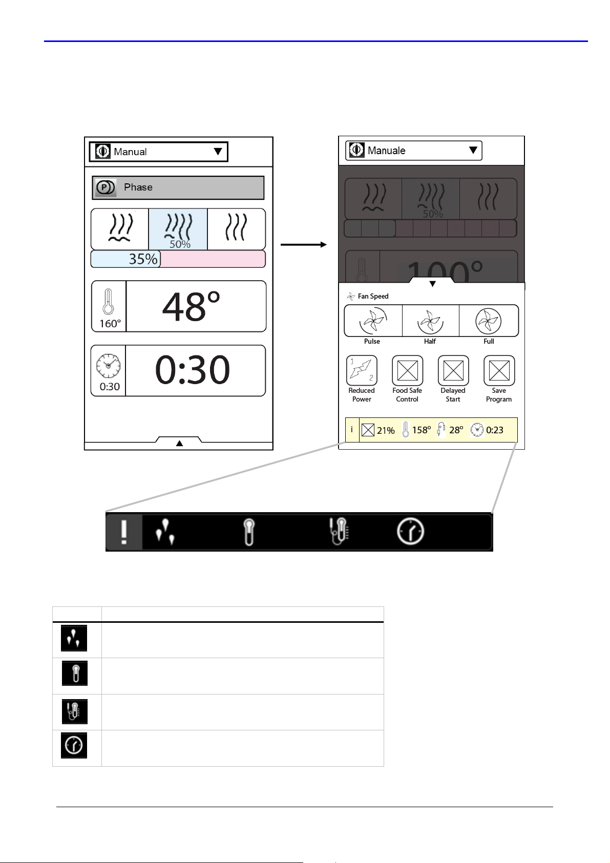
4.2 Drawer utilities & information bar
The main information about the status of the oven are visible in the drawer utilities in the
bottom of the screen (in the “manual” and “programs” environment).
ICON
21% 120° 119°
“information bar”
DESCRIPTION
Cavity humidity (%)
Cavity temperature
Meat probe temperature
(the minimum of the 6 measured points)
Clock
20:15
file: 0411400000 TOUCH service manual EN ©Copyright 2010 by Electrolux Professional
Issued by Customer Support Oven Platform
P.12/52
SERVICE MANUAL
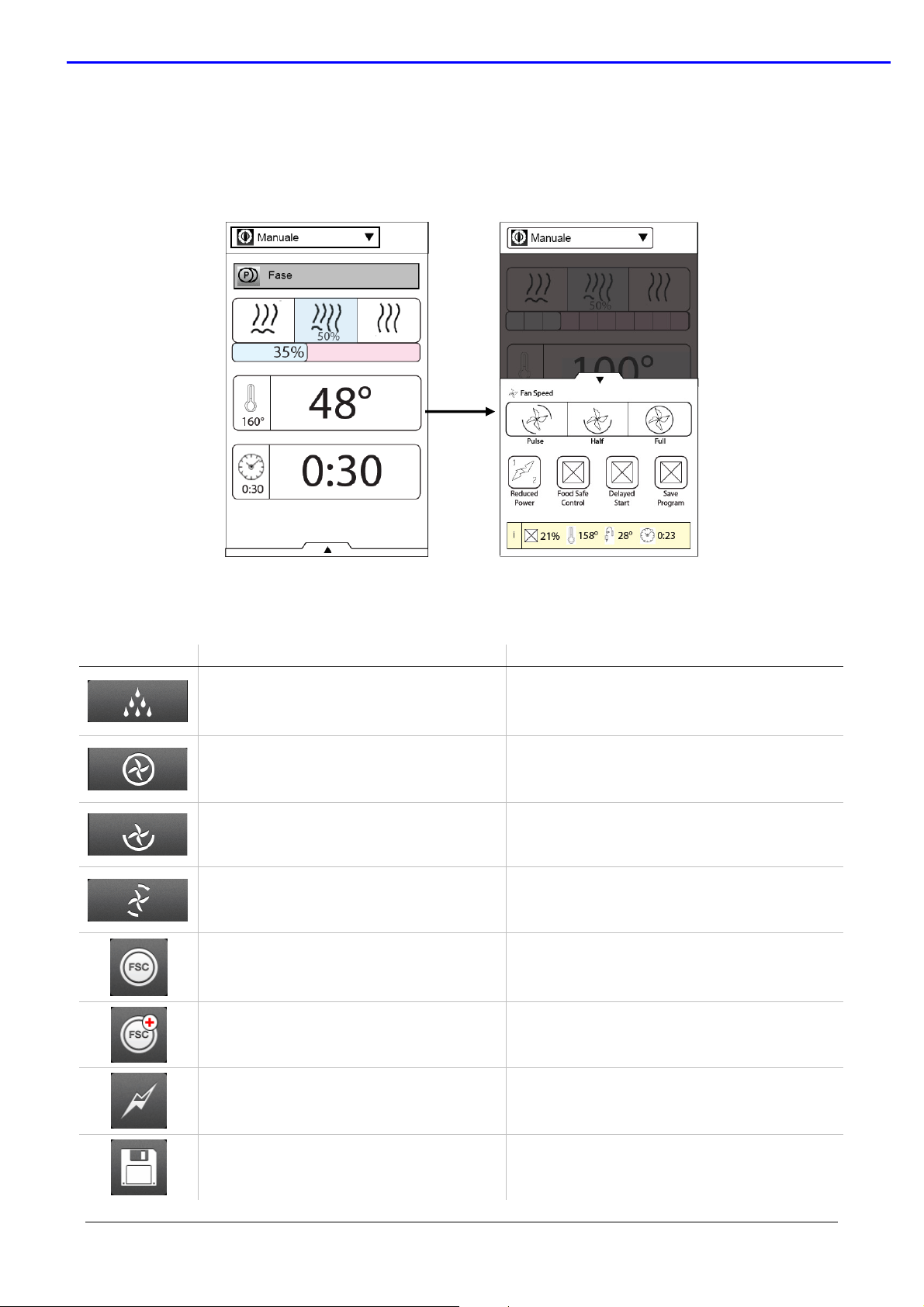
4.3 Drawer cooking utilities
Press the drawer icon in the bottom of the screen to see the special cooking utilities (in the
“manual” and “programs” environment.)
Press the relevant icon to activate the utilities.
Oven Lenghtwise – Touch Level Code: 0411400000
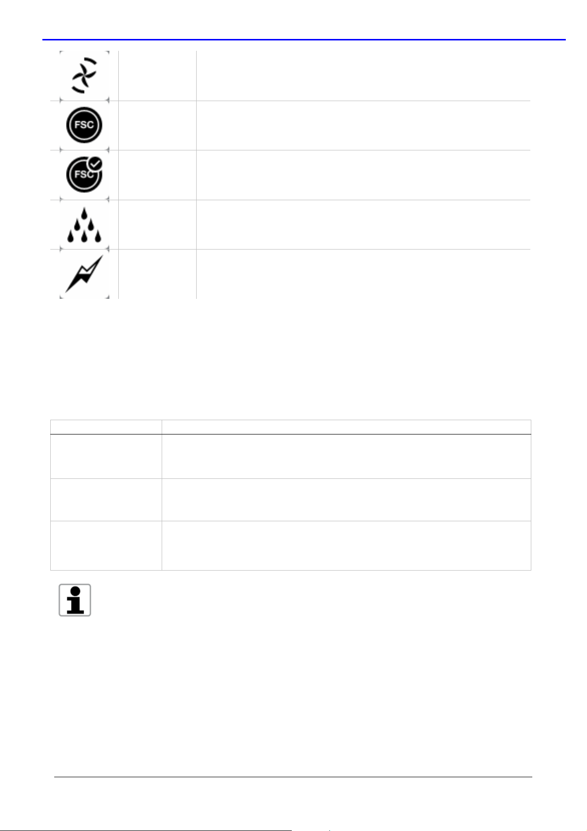
ICON
Manual cavity water injection: time
Full fan speed
Half fan speed Cooking cycle with half fan speed
Pulse fan speed
Food Save Control (FSC) standard
risk
Food Save Control (FSC) high risk
NAME DESCRIPTION
Only for convection cooking cycle.
Range: 10…120sec.
Cooking cycle with full fan speed
(default selection)
Cooking cycle with pulse fan speed: fan
ON when the cavity heating is ON, OFF
when the cavity heating is OFF
Food save control for not manipulated
food
Food save control for manipulated food
or for food with high risk (es. pork or
fish)
Reduced power
Save cooking program
file: 0411400000 TOUCH service manual EN ©Copyright 2010 by Electrolux Professional
Issued by Customer Support Oven Platform
cavity/ boiler heating element with
reduced power
Save cooking program in the
“programs” environment
P.13/52
SERVICE MANUAL
Oven Lenghtwise – Touch Level Code: 0411400000
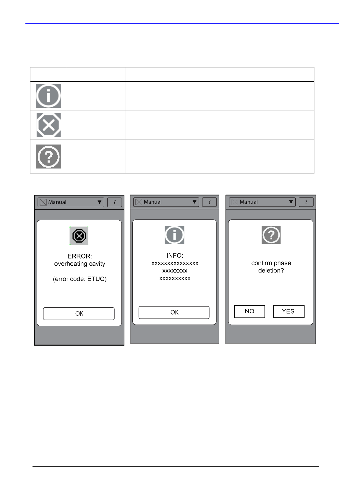
4.4 Message dialogs
During the use of the oven the screen can show different messages:
ICON POP UP DESCRIPTION
Information
dialog
To display information that the user has requested or
should know.
Allarm /
warning dialog
For warning issue or alarm that the user must know. In
some case the warning can contain a OK button
Question dialog Used for question like YES/NO
file: 0411400000 TOUCH service manual EN ©Copyright 2010 by Electrolux Professional
Issued by Customer Support Oven Platform
P.14/52
SERVICE MANUAL
Oven Lenghtwise – Touch Level Code: 0411400000
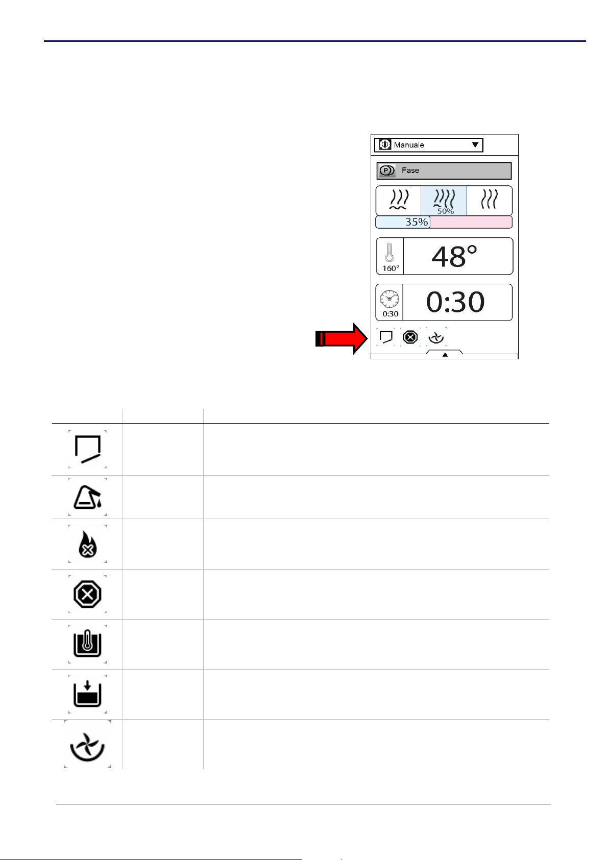
4.5 Information area (warning, alarms and utility)
In the cleaning and cooking environment (manual, programs and automatic) it’s active in the
bottom part of the screen an area where some information are visible:
COOKING UTILITY ON (icon);
WARNING (blinking icon);
ALARM (blinking icon).
Press the icon for:
To disable the relevant cooking utility;
To visualize a message dialog about
alarm/warning icon.
INFORMATION AREA: TABLE OF THE ICONS
ICON TYPE DESCRIPTION
Warning Door oven open
Warning “Descaling” warning of the boiler
Allarm
Allarm Press the icon to visualize the type of alarm.
Warning Preheating of the boiler ON
Warning Water fill of the boiler ON
Utility ON
Burner’s allarm. Press the icon to visualize the message dialog
with description.
Half speed of the fan during cooking cycle
file: 0411400000 TOUCH service manual EN ©Copyright 2010 by Electrolux Professional
Issued by Customer Support Oven Platform
P.15/52
SERVICE MANUAL
Oven Lenghtwise – Touch Level Code: 0411400000
Utility ON
Utility ON
Pulse fan speed during cooking cycle
FSC standard utility ON
Utility ON
FSC high risk utility ON
Utility ON
Manual water spray utility ON
Utility ON
Half power utility ON
4.6 Advanced service and parameters environment
There are 3 different environments for the Service and the advanced programming:
ENVIRONMENT DESCRIPTION
Settings
Data monitor
Service Utilities
For each environment see the referent chapter
For to programming the USER and SERVICE parameters.
(selected by main menu)
Data about status of the oven (service function)
Visible when the parameter DATM nr97 is set a 1
Download / upload of the cooking programs and software Touch
screen. (visible using the USB port)
file: 0411400000 TOUCH service manual EN ©Copyright 2010 by Electrolux Professional
Issued by Customer Support Oven Platform
P.16/52
 Loading...