

Electrolux AOS061GAPQ Installation Manual
air-o-steam® ELECTRIC COMBI OVENS
6 GN 1/1
260450 260462 260456
260451 260463 260457
°
**
°
**
°
**
400 230 200
2. TABLE 1: TECHNICAL DATA
INSTRUCTIONS FOR INSTALLATION AND USE
Table of contents Page
- Installation diagram .......................................................... 2
- Appliance identification ................................................... 9
I. MAIN FEATURES ............................................................. 10
1. Description of appliance ............................................ 10
2. Table 1: Technical data ................................................. 11
3. Precautions .................................................................. 12
4. Safeguarding the environment ................................... 13
4.1 Packaging .............................................................. 13
4.2 Use ......................................................................... 13
4.3 Cleaning ................................................................. 13
4.4 Disposal ................................................................. 13
II. INSTRUCTIONS FOR INSTALLATION ........................... 14
1. Place of Installation .................................................... 14
1.1 Ventilation ................................................................. 14
1.2 Reference standards................................................ 14
1.3 Unpackaging ............................................................ 14
1.4 Immediately inspect for shipping damage ............... 14
2. Positioning .................................................................... 14
3. Combusted gas discharge .......................................... 14
3.1 Foreword .................................................................. 14
Installation of accessories ............................... 15
3.2
3.3 Warnings regarding the fluimg system .................. 15
4. Electrical connection .................................................. 15
4.1 Installing the power supply cable ........................... 16
5. Water mains connection ............................................. 16
5.1 Water supply characteristics .................................. 16
5.2 Water drain system ................................................ 16
6. Gas connection ........................................................... 17
6.1 Warning .................................................................. 17
6.2 Nominal heat output ............................................... 17
6.2 Checking the supply pressure ............................... 17
7. Safety devices ............................................................. 17
8. Operation check .......................................................... 17
9. Servicing ....................................................................... 17
10. Troubleshooting ........................................................... 18
11. Layout of main components ..................................... 18
III. INSTRUCTIONS FOR USE ............................................ 19
1. Opening the oven door ............................................... 19
1.1 6- and 10-grid models ............................................ 19
1.2 20-GRID models .................................................... 19
2. Closing the oven door ................................................ 19
2.1 6- and 10-GRID models ......................................... 19
2.2 20-GRID models .................................................... 19
3. Description of the control panel ................................ 20
3.1 Introduction ............................................................ 20
3.2 Main controls .......................................................... 20
3.3 Main cooking modes .............................................. 20
3.4 Special cooking modes .......................................... 20
3.5 Additional functions ................................................ 21
USING THE OVEN ................................................................. 22
4. Introduction ................................................................. 22
4.1 Switching the oven on ............................................ 22
4.2 Selecting the controls ............................................ 22
4.3 Manual controls ...................................................... 22
4.4 Automatic controls ................................................. 26
5. Information and error codes ...................................... 29
6. SWITCHING off in the event of a fault ....................... 30
7. Care and maintenance ................................................ 30
7.1 Periodical maintenance of the BOILER ................. 31
7.2 Replacing CONSUMABLE components ................ 32
7.3 Special cleaning instructions ................................. 32
- CONTROL PANEL FIGURES .......................................... 105
USA
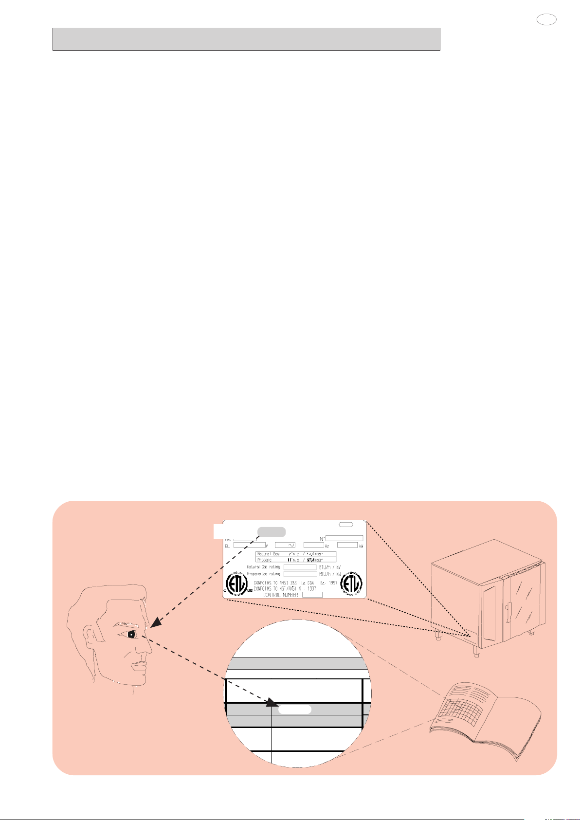
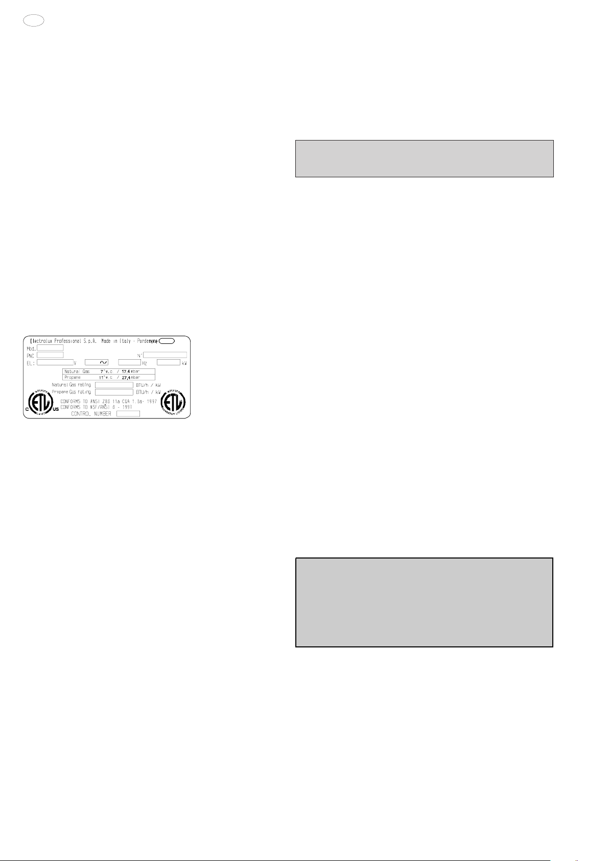
- APPLIANCE IDENTIFICATION
5938 026 00
Rating plate
PNC 9PDX 260462 05
260462
9

USA
I. MAIN FEATURES
1. DESCRIPTION OF APPLIANCE
This booklet describes a number of appliance models.
For more detailed information about the model in your possession,
refer to "Technical Data" table 1.
The appliance has the following features:
• Digital temperature controlle.
• Thermostatic probe for measuring the core temperature of products (core temperature probe).
• Automatic flush to drain every two hour to prevent the build-up of
lime-scale in the boiler.
• Periodic draining and automatic washing of the boiler to prevent
the build-up of lime-scale.
• Boiler lime-scale level indicator (see corresponding paragraph).
• Oven chamber automatic fast steam drain device for gratins.
• Air-break (anti-backup drain) device to prevent backflows from
the drain system from entering the oven.
• Halogen lighting in the cooking chamber.
• Double-action door opening safety mechanism designed to
protect the user from scalding steam.
• Double-glazed oven door for reduced heat dispersion into the
kitchen and low temperatures on the exterior of the oven.
• Self-diagnostics system indicating oven faults using error codes
(see "Information and error codes ").
10
5938 026 00
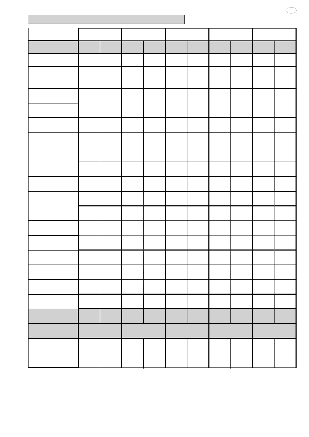
2. TABLE 1: TECHNICAL DATA
Boil
Boil
USA
GRID S
P NC *
CONVECTOR °
BOILER **
SUPPLY VOLTAGE
Total W atts
Maximum load capacities
(food)
Net w eight
Shipping we ight
Shipping width
Shipping height
Shipping depth
6 GN 1/1 10 GN 1/1 10 GN 2/1 20 GN 1/1 20 GN 2/1
260860 260870 260862 260872 260864 260874 260866 260876 260868 260878
° ° ° ° ° ° ° ° ° °
** ** ** ** ** ** ** ** ** **
208V 2ph
60Hz
6amps
120V 1ph
60Hz
10amp
208V 2ph
60Hz
6amps
120V 1ph
60Hz
10amps
208V 2ph
60Hz
6amps
120V 1ph
60Hz
10amps
208V 2ph
60Hz
10amps
120V 1ph
60Hz
16amps
208V 2ph
60Hz
15amps
0,25 kW 0,25 kW 0,3 kW 0,3 kW 1 k W 1 kW 0,5 kW 0,5 kW 2 kW 2 kW
66 lbs.
(30 kg)
253.53 lbs.
(115 kg)
295.42 lbs.
(134 kg)
37 1/64"inch
(940 mm)
40 15/16" inch
(1040 mm )
38 9/16"inch
(980 mm)
66 lbs.
(30 kg)
253.53 lbs.
(115 kg)
295.42 lbs.
(134 kg)
37 1/64"inch
(940 mm)
40 15/16" inch
(1040 mm )
38 9/16"inch
(980 mm)
110 lbs.
(50 kg)
319.67 lbs
(145 kg)
363.76 lbs.
(165 kg)
37 1/64"inch
(940 mm)
49 5/8"inch
(1260 mm)
38 9/16"inch
(980 mm)
110 lbs.
(50 kg)
319.67 lbs
(145 kg)
363.76 lbs.
(165 kg)
37 1/64"inch
(940 mm)
49 5/8"inch
(1260 mm)
38 9/16"inch
(980 mm)
220 lbs.
(100 kg)
504.86 lbs
(229 kg)
538 lbs
(244 kg)
50"inch
(1270 mm)
52 3/8"inch
(1330 mm)
44 7/8"inch
(1140 mm)
220 lbs.
(100 kg)
504.86 lbs
(229 kg)
538 lbs
(244 kg)
50"inch
(1270 mm)
52 3/8"inch
(1330 mm)
44 7/8"inch
(1140 mm)
220 lbs.
(100 kg)
533.52 lbs.
(242 kg)
639.34 lbs.
(290 kg)
37 1/64"inch
( 94 0 mm)
79 1/2"inch
(2020 mm)
42 1/2"inch
(1080 mm)
220 lbs.
(100 kg)
533.52 lbs.
(242 kg)
639.34 lbs.
(290 kg)
37 1/64"inch
(94 0 mm)
79 1/2"inch
(2020 mm)
42 1/2"inch
(1080 mm)
440 lbs.
(200 kg)
551.16 lbs
(250 kg)
573 lbs
(260 kg)
47 5/8"inch
(1210 mm)
70 7/8"inch
(1800 mm)
41 3/4"inch
(1060 mm)
120V 1ph
60Hz
20amps
440 lbs.
(200 kg)
551.16 lbs
(250 kg)
573 lbs
(260 kg)
47 5/8"inch
(1210 mm)
70 7/8"inch
(1800 mm)
41 3/4"inch
(1060 mm)
ISO 7/1 ga s
connectionDiameter
Nominal hea t output
NATURAL
er unit nominal
hea t output
NATURAL
Convector unit nominal
heat output
NATURAL
Nominal hea t output
PROPANE
er unit nominal
hea t output
PROPANE
Convector unit nominal
heat output
PROPANE
Gas type
Construction type
Diagram of fume s
discharge system
NATURAL pre ssure
1/2 " M 1/2" M 1/2" M 1/2" M 1/2 " M 1/2" M 1" M 1" M 1" M 1" M
68303.6
btu/h
(20 kW)
40982.1
btu/h
(12 kW)
40982.1
btu/h
(12 kW)
61473.2
btu/h
(18 kW)
35859.4
btu/h
(10.5 kW)
35859.4
btu/h
(10.5 kW)
NA TURA L
PROPA NE
A3
B13
68303.6
btu/h
(20 kW)
40982.1
btu/h
(12 kW)
40982.1
btu/h
(12 kW)
61473.2
btu/h
(18 kW)
35859.4
btu/h
(10.5 kW)
35859.4
btu/h
(10.5 kW)
NATURAL
PROPANE
A3
B13
136607.2
btu/h
(40 kW)
78549.1
btu/h
(23 kW)
78549.1
btu/h
(23 kW)
126361.6
btu/h
(37 kW)
71718.8
btu/h
(21 kW)
71718.8
btu/h
(21 kW)
NATURAL
PROPANE
A3
B13
136607.2
btu/h
(40 kW)
78549.1
btu/h
(23 kW)
78549.1
btu/h
(23 kW)
126361.6
btu/h
(37 kW)
71718.8
btu/h
(21 kW)
71718.8
btu/h
(21 kW)
NATURAL
PROPANE
A3
B13
177589.3
btu/h
(52 kW)
102455.4
btu/h
(30 kW)
105870.5
btu/h
(31 kW)
160513.4
btu/h
(47 kW)
88794.7
btu/h
(26 kW)
95625.0
btu/h
(28 kW)
NATURAL
PROPANE
A3
B13
177589.3
btu/h
(52 kW)
102455.4
btu/h
(30 kW)
105870.5
btu/h
(31 kW)
160513.4
btu/h
(47 kW)
88794.7
btu/h
(26 kW)
95625.0
btu/h
(28 kW)
NATURAL
PROPANE
A3
B13
232232.2
btu/h
(68 kW)
102455.4
btu/h
(30 kW)
160513.4
btu/h
(47 kW)
208325.9
btu/h
(61 kW)
88794.7
btu/h
(26 kW)
143437.5
btu/h
(42 kW)
NATURAL
PROPANE
A3
B13
232232.2
btu/h
(68 kW)
102455.4
btu/h
(30 kW)
160513.4
btu/h
(47 kW)
208325.9
btu/h
(61 kW)
88794.7
btu/h
(26 kW)
143437.5
btu/h
(42 kW)
NATURAL
PROPANE
A3
B13
379084.9
btu/h
(111 kW)
218571.5
btu/h
(64 kW)
218571.5
btu/h
(64 kW)
334687.5
btu/h
(98 kW)
191250.0
btu/h
(56 kW)
191250.0
btu/h
(56 kW)
NATURAL
PROPANE
A3
B13
379084.9
btu/h
(111 kW)
218571.5
btu/h
(64 kW)
218571.5
btu/h
(64 kW)
334687.5
btu/h
(98 kW)
191250.0
btu/h
(56 kW)
191250.0
btu/h
(56 kW)
NATURAL
PROPANE
A3
B13
1a-1b-1c 1a-1b-1c 1a-1b-1c 1a-1b-1c1a-1b-1c
7"w c
(17,4mbar)
7"w c
(17,4mbar)
7"w c
(17,4mbar)
7"w c
(17,4mbar)
7"w c
(17,4mbar)
7"w c
(17,4mbar)
7"w c
(17,4mbar)
7"w c
(17,4mbar)
7"w c
(17,4mbar)
7"w c
(17,4mbar)
PROPANE pressure
11"w c
(27,4mbar)
11"w c
(27,4mbar)
11"w c
(27,4mbar)
Noise emission data: Noise emissions generated by the appliances described in this booklet do not exceed 70 dB (A).
Your appliance model is indicated in the box marked PNC on
*
the Identification dataplate affixed to the bottom left hand side of
5938 026 00
the oven.
11"w c
(27,4mbar)
11
11"w c
(27,4mbar)
11"w c
(27,4mbar)
11"w c
(27,4mbar)
11"w c
(27,4mbar)
11"w c
(27,4mbar)
11"w c
(27,4mbar)
USA
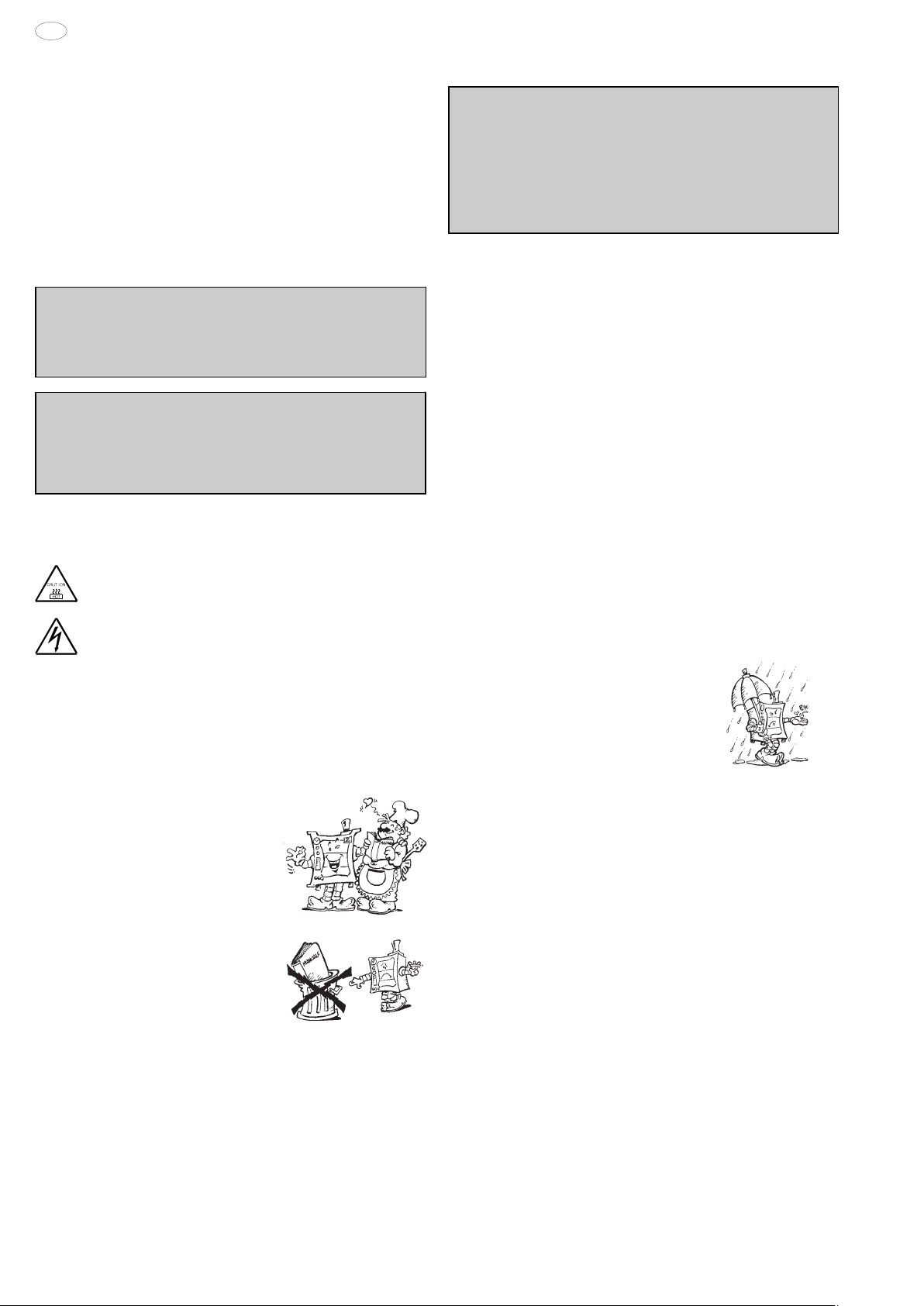
3. PRECAUTIONS
• The following terms alert you to potentially dangerous conditions
to the operator, service personnel or to the equipment.
• Danger! This term warns of immediate hazards which will result in
severe injury or death.
• Warning! This term refers to a potential hazard or unsafe
practice which could result in injury or death.
• Notice. This term refers to information that needs special
attention or must be fully understood, even though not dangerous.
• Keep the appliance area free and clear from combustibles.
Warning
For your safety, do not store or use gasoline or other
flammable, vapors and liquids in the vicinity of this or any other
appliance.
Keep area around appliances free and clear of combustibles
Warning!
Failure to properly vent the oven can be hazardous to the
health of the operator; and will result in operational problems,
unsatisfactory baking, and possible damage to the equipment.
Damage sustained as a direct result of improper ventilation will
not be covered by the Manufacturer's warranty.
NOTICE: INTENDED FOR COMMERCIAL USE ONLY. NOT
FOR HOUSEHOLD USE.
Fire hazard.
CAUTION HOT SURFACES
CAUTION RISK ELECTRIC SHOCK
Important: The installation instructions contained herein
are for the use of qualified installation and service
personnel only. Installation or service by other than
qualified personnel may result in damage to the appliance
and/or injury to the operator. FAILURE TO COMPLY
WITH INSTALLATION INSTRUCTION OR IMPROPER
INSTALLATION WILL VOID WARRANTY AND
RESPONSIBLITIES OF THE MANUFACTURE.
• Our appliances have been studied and optimized to give the
highest performance. This appliance is intended for industrial use
only and is specifically designed to cook food. Any other use will be
considered “improper use” and will void the warranty and
manufacturer liability.
WARNING: ANY POTENTIAL USER OF THE EQUIPMENT
SHOULD BE TRAINED IN SAFE AND CORRECT OPERATIONG
PROCEDURES.
WARNING: BEFORE SERVICING, DISCONNET THE
ELECTRICAL SERVICE AND PLACE A RED TAG AT THE
DISCONNECT SWITCH TO INDICATED WORK IS BEING DONE
ON THAT CIRCUIT.
NOTICE: Using any parts other than OEM original spare parts
relieves the manufacturer of all warranty and liability.
NOTICE: Manufacturer reserves the right to change specifications
at any time without notice.
Failure to comply with the above requirement may jeopardise
the safety of the appliance and invalidate the guarantee.
WARNING: DO NOT SPRAY THE OUTSIDE OF THE
APPLIANCE WITH WATER OR CLEAN WITH A WATER JET.
CLEANING WITH A WATER JET CAN IMPREGNAT
CHLORIDES INTO THE STAINLESS STEEL, CAUSING THE
ONSET OF CORROSION.
CAUTION: Do not locate unit adjacent to any high heat or
grease producing piece of equipment, such as a range top,
griddle, fryer, etc., that could allow radiant heat to raise the
exterior temperature of the Air-O-Steam Oven.
• Carefully read this instruction booklet, as it contains important
advice for safe installation, operation and maintenance.
• Keep this instruction booklet in a safe place for future reference.
• The installation of this unit must conform to local codes or, in the
absence of local codes, to all National Codes governing plumbing,
sanitation, safety and good trade practices.
WARNING: The equipment warranty is not valid unless the
appliance is installed, started and demonstrated under the
supervision of a factory trained installer.
WARNING: The unit must be installed by Personnel who are
qualified to work with electricity and plumbing. Improper installation
can cause injury to personnel and/or damage to the equipment.
The unit must be installed in accordance with applicable codes.
WARNING: DO NOT USE PRODUCTS CONTAINING
CHLORINE (BLEACH, HYDROCHLORIC ACID ETC.) EVEN
DILUTED, TO CLEAN STEEL SURFACES.
WARNING: DO NOT USE CORROSIVE SUBSTANCES (E.G.
MURIATIC ACID) TO CLEAN THE FLOOR UNDER THE
APPLIANCE.
12
5938 026 00

4. SAFEGUARDING THE ENVIRONMENT
4.1 PACKAGING
• All the packaging materials used are environmentally safe and
friendly. They may be stored without fear or danger. They may be
recycled or burned in a special waste incineration plant. Recyclable
plastic components are marked as follows:
polyethylene : external wrapping film, instructions
PE booklet bag and gas injectors bag
polypropylene: top packaging panels and straps
pp
expanded polystyrene: protective surround elements
PS
4.2 USE
• The appliance has been designed and perfected under laboratory
testing conditions to offer exceptional levels of performance.
However, to minimise energy consumption (electricity, gas and
water), do not leave the appliance in operation for long periods
without food in the oven chamber and avoid conditions that
reduce efficiency (e.g. door open). We also recommend preheating
the appliance immediately prior to use.
USA
4.3 CLEANING
• To minimise the emission of pollutants into the environment,
clean the appliance (externally and, where necessary, internally)
with products that are at least 90% biodegradable.
4.4 DISPOSAL
• Appliances that have reached the end of their service life should
be suitably disposed of.
• The appliance is made from more than 90% recyclable materials
(stainless steel, iron, aluminium, galvanised sheet steel, etc.).
These materials may therefore be scrapped in accordance with
local waste disposal regulations at a conventional recycling plant.
• Make the appliance unusable by cutting off the power cord. Also
remove any compartment or interior closure device fitted on the
appliance to prevent persons from becoming trapped inside.
5938 026 00
13

USA
II. INSTRUCTIONS FOR INSTALLATION
Important
perform the operations described in this chapter. Since the
appliance must be switched on to make certain
adjustments, exercise the utmost care when working in the
vicinity of live electrical parts.
: The oven outer panels must be removed to
1. PLACE OF INSTALLATION
1.1 VENTILATION
The necessity for a properly designed and installed ventilation
system cannot be over emphasized. The ventilation system will
allow the unit to function properly while removing unwanted vapors
and products of combustion from the operating area.
The appliance must be vented with a properly designed mechanically
driven exhaust hood. The hood should be sized to completely
cover the equipment plus an overhang of a least 6"/15.3cm on all
sides not adjacent to a wall. The capacity of the should be sized
appropriately and provisions for adequate makeup air.
Refer to your local ventilation codes. In the absence of local codes,
refer to the National ventilation code titled, “Standard for the
Installation of Equipment for the Removal of Smoke and Grease
Laden Vapors from Commercial Cooking Equipment”, NFPA-96Latest Edition.
It is recommended that the ventilation system and duct work be
checked at prevailing intervals as specified by the hood manufactured
• The appliance must only be installed in adequately ventilated
premises.
NOTICE: Proper ventilation is the owner's is responsibility. Any
problem due to improper ventilation will not be covered by the
warranty.
1.2 REFERENCE STANDARDS
Note: The electric supply installation must satisfy the requirements
of the appropriate statutory authority, such as the National
Electrical Code (NEC) ANSI/NFPA70, (U.S.A..): the Canadian
Electrical Code, CSA C22.2; or other applicable regulations.
Note: The electric supply connection must meet all national and
local electrical code requirements.
Note: The installation of this unit must conform to local codes or,
in the absence of local codes, to all National Codes governing
plumbing, sanitation, safety and good trade practices, and to the
National Gas Code ANSI Z223.1.
• Local codes regarding installation vary greatle from one area to
another. This equipment is to be installed to comply with the
applicable federal, state or local codes.
The installation instructions contained herein are for the use of
qualified installation and service personnel only. Installation or
service by other than qualified personnel may result in damage to
the appliance and/or injury to the operator.
FAILURE TO COMPLY WITH INSTALLATION INSTRUCTION
OR IMPROPER INSTALLATION WILL VOID WARRANTY AND
RESPONSIBLITIES OF THE MANUFACTURE.
The National Fire Protection Association, Inc states in its NFPA
96 latest edition that local codes are the "authority having
jurisdiction" when it comes to installation requirements for
equipment. Therefore, installations should comply with all local
codes.
1.3 UNPACKAGING
• Remove the appliance from the packaging and take away the
protective film that covers the appliance's external panels carefully to avoid leaving any trace of glue. If necessary remove the
glue using an a non-corrosive solvent, rinsing it off and drying
carefully.
• Dispose of packaging material in compliance with the regulations
in force in the country where the product is to be used.
1.4 IMMEDIATELY INSPECT FOR SHIPPING DAMAGE
The container should be examined for damage before and during
unloading. The freight carrier has assumed responsibility for its
safe transit and delivery. If damaged equipment is received,
either apparent or concealed, a claim must be made with the
delivering carrier. Apparent damage or loss must be noted on the
freight bill at the time of delivery. The freight bill must then be
signed by the carrier representative (Driver). If the bill is not
signed, the carrier may refuse the claim. The supply can supply
the necessary forms. A request for inspection must be made to
the carrier within 15 days if there is concealed damage or loss that
is not apparent until after the equipment is uncrated. The carrier
should arrange an inspection. Be certain to hold all contents plus
all packing material. Under no circumstances should a damaged
appliance be returned to the manufacturer without prior notice
and written authorization.
2. POSITIONING
• Refer to the installation diagrams at the beginning of this
booklet for the space requirements and connection dimensions of
the appliance.
• Clearance of approximately 23.62" (50cm) must be left between
the appliance’s left side panel and adjacent structures in order to
provide space for maintenance operations when needed; the
right side panel and the rear panel of the appliance must be at
least 1.97" (5cm) from adjacent structures.
• Place the appliance in the required position and level the oven
with a slight pitch toward the rear to help drain water from
chamber using the appropriate bullet feet.
• The appliance is not suitable for built-in installation.
Warning: The oven must be installed on an even (level) nonflammable flooring and any adjacent walls must be non-flammable.
Recommended minimum clearance are specified in this manaul.
Important
Make sure steam from the oven’s drain or adjacent
appliances does not enter the aeration vents under the
appliance, designed to cool internal components
located at the bottom of the appliance.
:
3. COMBUSTED GAS DISCHARGE
3.1 FOREWORD
In relation to the combustion technology utilised, gas fired steam/
convection ovens are classified in accordance with their
"Construction Type". For each of these types of appliances
applicable regulations stipulate a specific type of combusted gas
discharge system.
Consequently, before installing the discharge system:
a) identify the "Construction type" of your model in Table 1
(technical data) or by checking the appliance identification
dataplate;
b) choose the diagram with the type of construction among
those shown as follows (fig. 1a-1b-1c), depending on how you
intend to exhaust the appliance fumes from the place of installation
(e.g. discharge under extraction hood, direct to the outside, or in
a central flue).
5938 026 00
14
USA
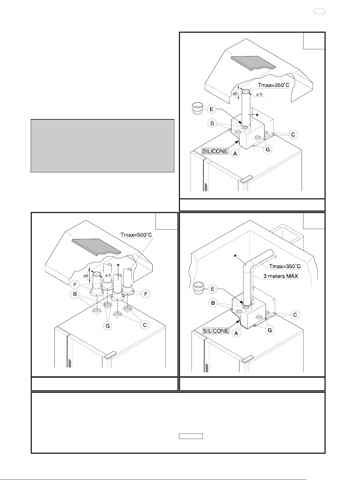
3.2 WARNINGS REGARDING THE FLUING SYSTEM
Before installation check, on the basis of the contents of the
reference standard, to ensure that the volume aspirated by the
fumes exhausting system is greater than the volume of combusted
gas produced by the appliance (see point 1.1).
If the solution of combusted gas discharge under an extractor
hood is chosen, observe the distance (shown in the figure)
between the top of the discharge pipe and the lowest point of the
hood filters. This distance is defined on the basis of discharge
pipe diameter "D".
In the case of discharge direction to the outside or into a central
flue (Fig. "1c"), the discharge ducts must NOT present an overall
length in excess of 762"(3 metres), must NOT have any reductions
in diameter, and must be subjected to periodic inspection and,
when necessary, cleaning.
Warning:
high temperatures, check the heat resistant properties of
extension ducts if fitted and the filters in the extractor hood
to ensure the materials are compatible with the temperature
conditions. In addition, periodically check the condition of
the filters which, if excessively fouled with fat and dirt, will
reduce the efficiency of the suction system and may catch
fire.
Since combusted gas (see figure) can reach very
3.3 INSTALLATION OF ACCESSORIES
Accessories can be easily installed by following the figures below
together with the relative key.
The screw holes for fixing accessories "A" and "F" are 0.14"(3.5
mm) in diameter and they must be drilled in-situ on the oven cover
in correspondence with the punch marks.
CONSTRUCTION TYPE
B13
DISCHARGE WITH SHROUD UNDER EXTRACTOR HOOD
1b
CONSTRUCTION TYPE
A3
1a
CONSTRUCTION TYPE
B13
1c
DIRECT UNDUCTED DISCHARGE UNDER EXTRACTOR HOOD
LEGENDA:
A: Cam / draught damper accessory
(to be ordered from manufacturer)
B: Boiler combusted gas discharge
C: Oven chamber convector combusted gas discharge
E: Adapter ring for commercial ducts
(to be ordered from manufacturer)
5938 026 00
DISCHARGE TO THE OUTSIDE OR CENTRAL FLUE WITH SHROUD
F: Conical connections for single outlet (supplied)
(always install)
G: Fixing screws (supplied);
*: Commercial extension pipes (not supplied)
SILICONE :
Apply silicone sealant between contact surfaces
15
USA
4. ELECTRICAL CONNECTION
• A fused disconnect switch or main circuit breaker (customer
furnished) MUST be installed in the electric supply line for the
appliance. It is recommended that this switch/circuit breaker
have lockout/tagout capability. Before making any electrical
connections to this appliance, check that the power supply is
adequate for the voltage, amperage, and phase requirements
on the rating plate.
• A safety cutout switch of suitable capacity with a contact
breaking distance of at least 3 mm must be fitted upstream of
the appliance.
The cutout switch must be installed near the appliance in the
permanent electrical system of the premises.
• The appliance must be electrically grounded in accordance
with local codes, or in the absence of local codes, with the
National Electrical Code, ANSI/NFPA 70, or the Canadian
Electrical Code, CSA C22.2, as applicable.
The grounding conductor must therefore be connected to the
terminal marked Gon the connection terminal board. The
appliance must also be connected to an earth grounding
system.
This connection is made using the stop screw marked E
located on the outside of the appliance near the power cable
inlet.
The grounding wire must have a minimum cross-section of
8 AWG (10 mm
4.1 INSTALLING THE POWER SUPPLY CABLE
To access the power supply cable connection terminal board,
proceed as follows:
Model 6 - 10 - 20 GN
• Remove the left side panel.
• Connect the power supply cable to the terminal board accord-
ing to the instructions given in the wiring diagram and fasten the
power supply cable by means of strain-relief fitting (not furnished
with the oven).
Failure to comply with safety rules and regulations relieves
the manufacturer of all liability.
The manufacturer requires when stacking units each appliance
have its own branch circuit protection. An air-o-steam® unit
stacked with an air-o-chill® unit should have a separate protection
for the upper and lower units.
2
).
RATING PLATE
Before fitting the filters allow the water to flow out for sufficient
time to flush any solid particles from the piping.
5.1 WATER SUPPLY CONNECTIONS
5.1.1 WATER INLET "N".
Attention
The water supply pipe (not supplied) must have a 3/4" dia (20
mm) pipe and must be without elbow fittings.
The steam condensation system must be connected to a cold
quality water supply in keeping with local plumbing codes, with
the following characteristics:
- total hardness: up to 400ppm (40°fH) .
- pressure: 22 to 36 psi (150-250 kPa); higher pressure
values result in increased water consumption.
Note:
To check correct water installation, make sure the rotating wash
arm (CLEANING SYSTEM) does not turn below 100 rpm (120
max).
5.1.2 WATER INLET "B".
(water pipe supplied)
The steam production system must be connected to a quality
water supply in keeping with local plumbing codes, with the
following characteristics:
- total hardness:
build-up of lime-scale inside the boiler.
On request the oven is supplied with an optional water softener
with automatic regeneration which must be installed on inlet line
"B". This device can also be fitted with an optional resin sanitizer
kit.
- pressure: 22 to 36 psi (150-250 kPa); higher pressure
values result in increased water consumption.
- chlorine ion concentration (Cl -): not more than ~10 ppm
(acceptable value) to avoid damaging the oven's internal steel
parts.
- pH: over 7.
The oven can be equipped with an optional special filtration unit
which is installed on inlet line "B". This unit also acts as a water
softener, reducing water hardness to less than
(optimum value).
- electrical conductivity: 50 to 2000 µS/cm (68°F)(20°C).
Important: The use of water treatment systems featuring
technology that differs from that of the systems supplied by the
manufacturer is prohibited and will automatically invalidate the
warranty.
The use of dosing systems designed to prevent the buildup of lime-scale in pipes (i.e. polyphosphate dosing
systems) is also prohibited since such systems may impair
the performance of the appliance.
5 - 50ppm (0.5 - 5 °fH) to reduce the
50ppm (5 °fH)
5. WATER MAINS CONNECTION
(Refer to the installation diagrams at the beginning of this booklet).
This equipment is to be installed to comply with the applicable
Federal, State, Local plumbing codes, or the Basic Plumbing
Code of the Building Officials and Code Administrators
International Inc. (BOCA) and Food Service Sanitation Manual
of the Food and Drug Administration (FDA).
The appliance is fitted with two separate water inlets ("B" and "N").
The water lines supplying both inlets must be fitted with a
mechanical filter and shut-off valve (keeping with local plumbing
codes).
5.2 WATER DRAIN SYSTEM
The oven is supplied with an air-break system to prevent any
backflow from the drainage system from reaching the oven’s internal circuits and the cooking chamber. The presence of this
system means that the drain pipe can be connected directly to
the mains drainage system or routed to a floor gulley with grating.
The flexible drainage hose or rigid pipe can be directed to the
side or rear of the appliance if the oven is not positioned against
a wall; this line must not be directed towards the front of the
appliance to prevent interference with roll-in grid racks. The drainage pipe internal diameter must be no smaller than the oven
16
5938 026 00
 Loading...