

Electrolux AOS061ECR2 Instructions For Installation And Use Manual

27
GB
5938 033 01
INSTRUCTIONS FOR INSTALLATION AND USE (for the United Kingdom)
Contents Page
- APPLIANCE IDENTIFICATION
ELECTRIC STEAM/CONVECTION AND CONVECTION OVENS
- CONTROL PANEL FIGURES .......................................... 247
260450-260510 260462 260456
26045
260451-260511 260463 260457
2604
°
**
°
**
°
**
400
230
200
6GN1/1
(AOS061E)
Made in E E C.
IP25
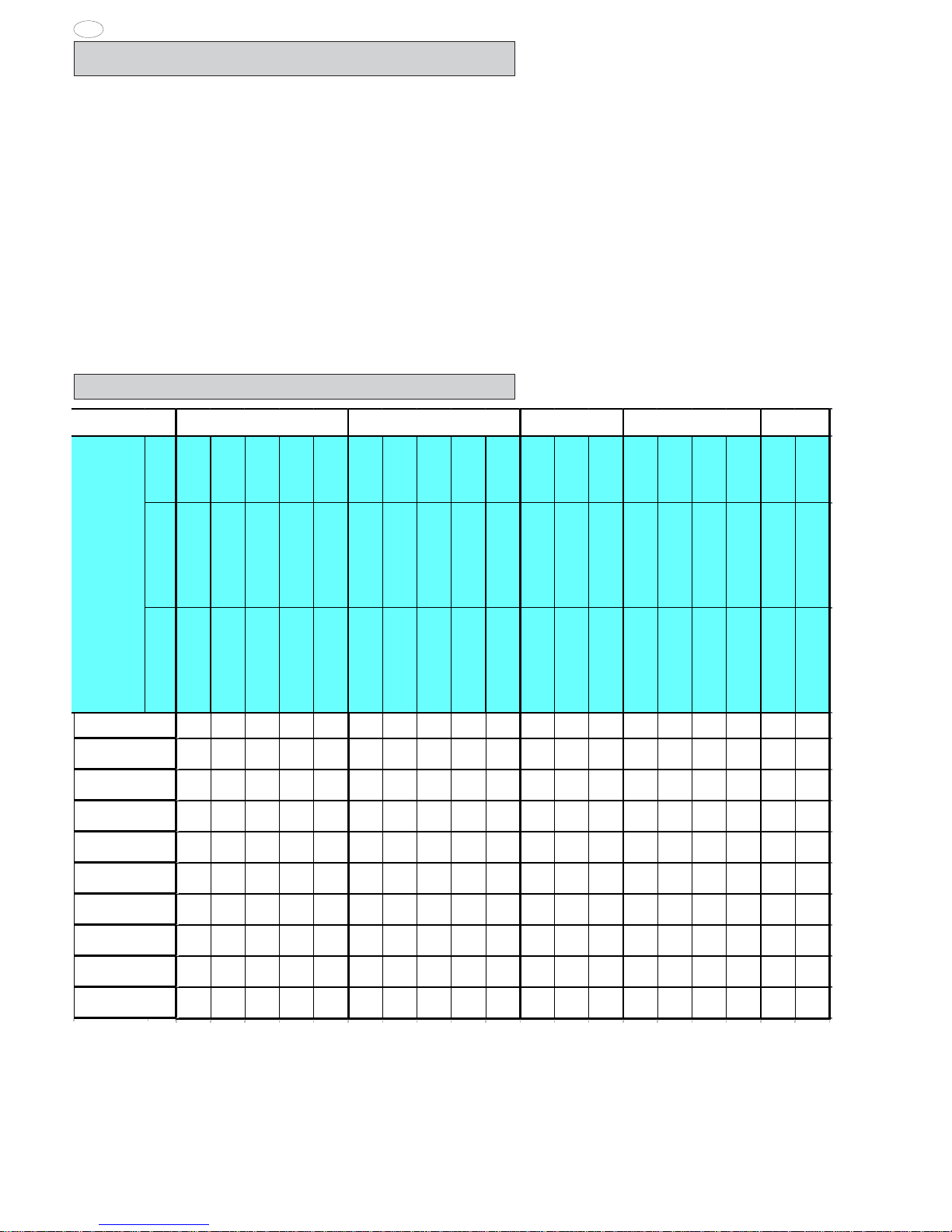
2. TABLE 1: TECHNICAL DATA
PNC 9PDX 260462 05
260462
Identification dataplate
- Installation diagrams ........................................................ 4
- Appliance identification .................................................. 27
I. MAIN FEATURES ............................................................. 28
1. Description of appliance ............................................. 28
2. Table 1: Technical data ................................................. 28
3. Precautions .................................................................. 29
4. Safeguarding the environment ................................... 29
4.1 Packaging ..............................................................29
4.2 Use ......................................................................... 29
4.3 Cleaning ................................................................ 2 9
4.4 Disposal ................................................................. 29
II. INSTRUCTIONS FOR INSTALLATION ............................ 30
1. Place of installation ..................................................... 30
1.1 Reference standards ............................................... 30
2. Positioning ..................................................................... 30
3. Electrical connection ................................................... 30
3.1 Installing the power supply cable .......................... 30
4. Water mains connection ............................................. 30
4.1 Water supply characteristics .................................. 30
4.2 Water drain system ................................................ 31
5. Safety devices ............................................................. 31
6. Operation check .......................................................... 31
7. Servicing ....................................................................... 32
8. Troubleshooting ............................................................ 32
9. Layout of main components ........................................ 32
III. INSTRUCTIONS FOR USE ............................................. 33
1. Opening the oven door ................................................ 33
1.1 6- and 10-grid models ........................................... 33
1.2 20-grid models ....................................................... 33
2. Closing the oven door ................................................. 33
2.1 6- and 10-grid models ........................................... 33
2.2 20-grid models ....................................................... 33
3. Description of the control panel ................................. 34
3.1 Introduction ............................................................ 3 4
3.2 Main controls ......................................................... 34
3.3 Main cooking modes ............................................. 34
3.4 Special cooking modes ......................................... 34
3.5 Additional functions ............................................... 35
USING THE OVEN ................................................................. 36
4. Operating level A, B and C ...................................... 36
4.1 Switching the oven on ........................................... 36
4.2 Selecting the controls ............................................ 3 6
4.3 Manual controls ..................................................... 36
4.4 Automatic controls ................................................. 40
5. Information and error codes ....................................... 43
6. Switching off in the event of a fault ............................ 44
7. Care and maintenance ................................................ 44
7.1 Periodic maintenance of the boiler ........................ 45
7.2 Replacing consumable components ..................... 4 6
7.3 Special cleaning instructions ................................. 4 6
28
GB
5938 033 01
Noise emission data: Noise emissions generated by the appliances described in this booklet do not exceed 70 dB (A).
*
Your appliance model is indicated in the box marked PNC on
the Identification dataplate affixed to the bottom left hand side of
the oven.
^ FUNCTIONAL LEVEL (C = Convect, Convection).
I. MAIN FEATURES
2. TABLE 1: TECHNICAL DATA
1. DESCRIPTION OF APPLIANCE
This booklet describes a number of appliance models.
For more detailed information about the model in your possession,
refer to "Technical Data" table 1.
The appliance has the following features:
• Digital temperature indicator.
• Thermostatic probe for measuring the core temperature of products (core temperature probe).
• Continuous monitoring of cooking parameters throughout the
entire cooking cycle.
• Periodic draining and automatic washing of the boiler to prevent
the build-up of lime-scale (only available on certain models).
• Boiler lime-scale level indicator (see corresponding
paragraph)(only available on certain models).
• Oven chamber automatic fast steam drain device for gratins.
• Air-break anti-backup drain device to prevent backflows from the
drainage system from entering the oven (only available on certain
models).
• Oven chamber lighting.
• Double-action door opening safety mechanism designed to
protect the user from scalding steam (only available on certain
models).
• Double-glazed oven door for reduced heat dispersion into the
kitchen and low temperatures on the exterior of the oven.
• Daily oven chamber cleaning cycle (CLEANING SYSTEM)(only
available on certain models).
• Self-diagnostics system indicating oven faults using error codes
(see "Information and error codes ").
267000
267010
237000
237010
647000
647070
267020
237020
267030
267002
267012
237002
237012
647002
647072
267022
237022
267032
267003
237003
647003
267063
267033
237033
267004
267014
237004
237014
647004
647074
267024
237024
267005
237005
647005
268000
268010
238000
238010
648000
648070
268020
238020
268030
268002
268012
238002
238012
648002
648072
268022
238022
268032
268003
238003
648003
268033
238003
268004
268014
238004
238014
648004
648074
268024
238024
268005
238005
648005
269000
269010
239000
239010
649000
649070
269020
239020
269002
269012
239002
239012
649002
649072
269022
239022
269003
239003
649003
269004
269014
239004
239014
649004
649074
269024
239024
269005
239005
649005
°
**
°
°
**
°
° **°
**
°
°
**
°
° **°
**
°
° **°
**
°
°
**
°
°
**
°
400
3 N~
400
3 N~
230
3 ~
230
3 ~
200
3 ~
400
3 N~
400
3 N~
230
3 ~
230
3 ~
200
3 ~
400
3 N~
400
3 N~
200
3 ~
400
3 N~
400
3 N~
230
3 ~
230
3 ~
400
3 N~
400
3 N~
50/60 50/60 50 /60 50/61 50/60 50/60 50/60 50/60 50/60 50/60 50/60 50/60 50/60 50/6050/60 50/60 50/60 50/60 50/60
10,1 10,1 10,1 10,1 10,1 17,5 17,5 17,5 17,5 17,5 25 25 25 34,5 34,5 34,5 34,5 50 50
25 25 32 32 40 32 32 50 50 63 63 63 100 63 63 125 125 100 100
5x2,5 5x2,5 4x4 4x4 4x4 5x4 5x4 4x10 4x10 4x10 5x10 5x10 5x16 5x10 5x10 4x25 4x25 5x16 5x16
0,19 0,19 0,19 0,19 0,19 0,19 0,19 0,19 0,19 0,19 0,75 0,75 0,75 0,38 0,38 0,38 0 ,38 1,5 1,5
9 9 9 17 17 17 24 24 24 20 48
9,69,69,69,69,61717171717242424343434344848
30 30 30 30 30 50 50 50 50 50 100 100 100 100 100 10 0 100 200 200
20 GN 2/1 6G N 1/1 10GN1/1 20 GN1/110 GN 2/1
A ^
B ^
C ^
PNC *
G RID S
CONVECTOR °
BOILE R **
POWER SUPPLY
VOLTAGE (VOLT)
FREQUENCY (Hz)
Max. elect ri cal p ower
input (Kw)
Main s fuses
(3 x 500V)
Power supply cable
cross-section (mm
2
)
Fan motor power rating
(Kw)
Steam unit power rating
(Kw)
Convection unit power
rating (Kw)
Max. food load (kg)
A ^
267000
267010
237000
237010
647000
647070
267020
237020
267030
267072
237002
237012
647002
647072
267022
237022
267032
267003
237003
647003
267063
267033
237033
267004
267014
237004
237014
647004
647074
267024
237024
267005
237005
647005
B ^
238000
238010
268200
268210
268300
238200
238210
648000
648070
268020
238020
268220
238220
268030
268230
238002
238012
268202
268212
268302
238202
238212
648002
648072
268022
238022
268222
238222
268032
268232
268003
238003
268203
238203
268303
648003
268033
268233
238003
238004
238014
268204
268214
268304
238204
238214
648004
648074
268024
238024
268224
238224
268005
238005
268205
268305
238205
648005
C ^
239000
239010
269200
269210
269300
269330
239200
239210
649000
649070
269020
239020
269220
239220
239002
239012
269202
269212
269302
269332
239202
239212
649002
649072
269022
239022
269222
239222
269003
239003
269203
269303
239203
649003
269204
269214
269304
239204
239214
649004
649074
269024
239024
269224
239224
269005
239005
269205
269305
239205
649005
20 GN 2/1 n° GRIGLIE 6GN 1/1 10 GN1/1 20GN1/110 GN 2/1
PNC *
29
GB
5938 033 01
3. PRECAUTIONS
• Before installing or using the appliance read this instruction
booklet carefully because it contains important information
concerning safety, operation and maintenance.
• Keep this instruction booklet in a safe place for future
consultation by other users or purchasers in the event that the
appliance is resold.
Important: Installation and maintenance of the appliance
and its conversion to a different gas supply must only be
performed by a qualified installer authorised by the
manufacturer.
• This appliance is intended for collective use and is expressly
designed for cooking food. Any other use is deemed improper.
The appliance must only be used by trained staff.
• This appliance is not intended for use by people (including
children) with limited physical, sensory or mental abilities or
without experience and knowledge of it, unless they are
supervised or instructed in its use by a person responsible for
their safety.
• Switch off the appliance if it breaks down or malfunctions.
• Only contact the technical service centre authorised by the
manufacturer for repairs and only use original spare parts.
Failure to comply with the above requirement may jeopardise
the safety of the appliance and invalidate the guarantee.
• Do not wash the appliance with water jets.
• Do not use products containing chlorine (bleach, hydrochloric
acid etc.) even diluted, to clean steel surfaces.
• Do not use corrosive substances (e.g. muriatic acid) to clean the
floor under the appliance.
• For more information, refer to the section on "Care and
maintenance".
4. SAFEGUARDING THE ENVIRONMENT
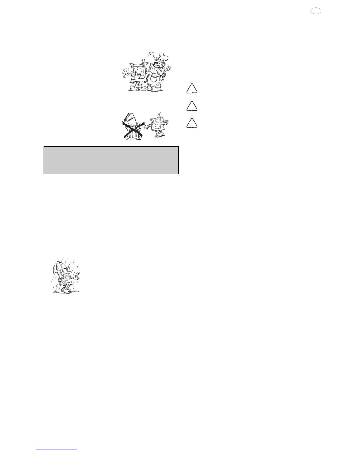
4.1 PACKAGING
• All the packaging materials used are environmentally friendly.
They may be stored at no risk or burnt at an authorised incineration
plant. Plastic materials suitable for recycling are marked with the
following symbols:
polyethylene : external wrapping film, instructions
PE booklet bag and gas injectors bag
polypropylene: top packaging panels and straps
pp
expanded polystyrene: protective surround elements
PS
4.2 USE
• The appliance has been designed and perfected under laboratory
testing conditions to offer exceptional levels of performance.
However, to minimise energy consumption (electricity, gas and
water), do not leave the appliance in operation for long periods
without food in the oven chamber and avoid conditions that
reduce efficiency (e.g. door open). We also recommend
preheating the appliance immediately prior to use.
4.3 CLEANING
• To minimise the emission of pollutants into the environment,
clean the appliance (externally and, where necessary, internally)
with products that are at least 90% biodegradable.
4.4 DISPOSAL
• The appliance must be disposed of properly at the end of its
service life.
• The appliance is made from more than 90% recyclable materials
(stainless steel, iron, aluminium, galvanised sheet steel, etc.).
These materials may therefore be scrapped in accordance with
local waste disposal regulations at a conventional recycling
plant.
• Make the appliance unusable by cutting off the power cord. Also
remove any compartment or interior closure device fitted on the
appliance to prevent persons from becoming trapped inside.
The symbol L on the product indicates that this product
should not be treated as domestic waste, but must be correctly
disposed of in order to prevent possible negative consequences
for the environment and the human health.
Regarding the recycling of this product, please contact the sales
agent or dealer of your product, your after-sales service or the
appropriate waste disposal service.
30
GB
5938 033 01
3.1 INSTALLING THE POWER SUPPLY CABLE
To access the power supply cable connection terminal board,
proceed as follows:
Model 6 - 10 - 20 GN
• Remove the left side panel.
• Connect the power supply cable to the terminal board according to the instructions given in the wiring diagram and fasten the
power supply cable by means of the cable clamp.
The manufacturer declines all responsibility if the applicable
safety regulations are disregarded.
4. WATER MAINS CONNECTION
(Refer to the installation diagrams at the beginning of this booklet).
When connecting the appliance to the water system with
flexible tubes they must be new and not used.
The appliance is fitted with two separate water inlets ("B" and "N").
The water lines supplying both inlets must be fitted with a
mechanical filter and shut-off cock.
Before fitting the filters allow the water to flow out for sufficient time
to flush any solid particles from the piping.
Pressure between 150 and 450 kPa (1.5-4.5 bar).
WATER INLET “N”
Attention (water inlet N)
If the supply pipes provided with the appliance are not long
enough for installation, use longer ones with int. diameter at
least ø 20 mm and free of elbow unions.
Note:
To check correct water installation, make sure the rotating wash
arm (CLEANING SYSTEM) does not turn below 100 rpm (120
max).
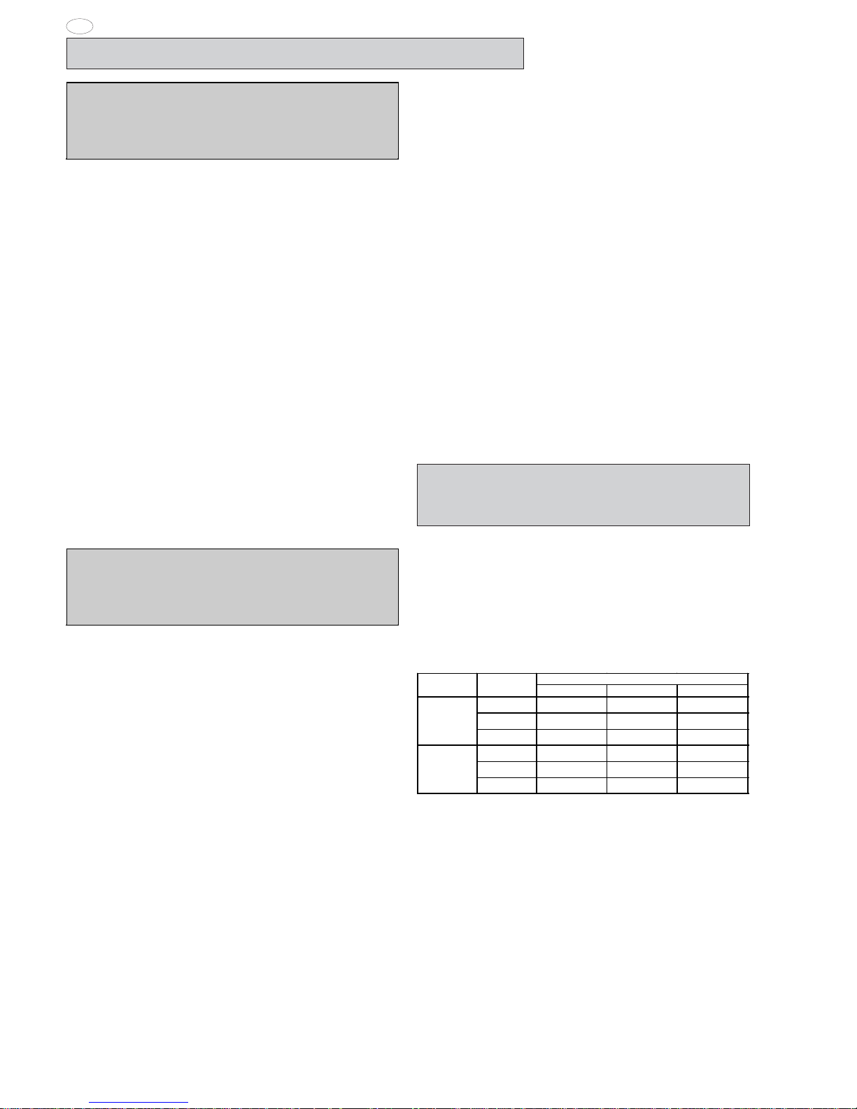
4.1 WATER SUPPLY CHARACTERISTICS
The appliance must be supplied with drinking water having
specific characteristics given in this section.
HARDNESS FILTER
°f pp m °dH
Water
in le t
Appl. Hardness
A ^ 0,5 - 5 5 - 50 0,28 - 2,8
B ^ 0,5 - 5 5 - 50 0,28 - 2,8
C ^ m ax 5 m ax 50 m ax 2,8
A ^ m ax 5 m ax 50 m ax 2,8
B ^ m ax 40 m ax 400 m ax 22
C ^ m ax 5 m ax 50 m ax 2,8
N
B
^ OPERATING LEVEL (C = Convect, Convection).
The hardness values given in the table are for reducing scaling
inside the steam generator and possible cooking compartment
washing system.
If the available water does not have these hardness characteristics
a water softener must be installed.
Therefore the Automatic Water Softener with automatic
regeneration for installing on the inlet line, can be requested as
an accessory; it has a Resin Sterilizer kit (also by request).
HARDNESS AND CHLORIDE FILTERS
The chloride concentration (Cl-) (ppm - mg/l) values with pH
(>7) and Conductivity (µS/cm) (measured at 20°C) must be
such as to not damage the steel structures inside the oven (only
water inlet B).
Therefore the characteristics of the available water must be
identified in the graph given at the end of this handbook (page
251), if necessary installing at the inlet the type of filter indicated
in the relevant area of the values.
II. INSTRUCTIONS FOR INSTALLATION
Important: The oven outer panels must be removed to
perform the operations described in this chapter. Since the
appliance must be switched on to make certain
adjustments, exercise the utmost care when working in the
vicinity of live electrical parts.
1. PLACE OF INSTALLATION
• The appliance must only be installed in adequately ventilated
premises.
1.1 REFERENCE STANDARDS
• Install the appliance according to the prescriptions of current
safety standards.
2. POSITIONING
• Unpack the appliance and carefully remove the protective film
from the outer panels to avoid leaving any trace of adhesive. Use
a suitable solvent to remove any adhesive residues.
• Dispose of the packaging as instructed in the chapter on
"Safeguarding the environment"
• Refer to the installation diagrams at the beginning of this
booklet for the space requirements and connection dimensions
of the appliance.
• Clearance of approximately 50 cm must be left between the
appliance’s left side panel and adjacent structures in order to
provide space for maintenance operations when needed; the
right side panel and the rear panel of the appliance must be at
least 10 cm from adjacent structures.
• Place the appliance in the required position and adjust the
height of the work surface using the adjustable feet.
• The appliance is not suitable for built-in installation.
Important:
Make sure steam from the oven’s drain or adjacent
appliances does not enter the aeration vents under the
appliance, designed to cool internal components
located at the bottom of the appliance.
3. ELECTRICAL CONNECTION
The appliance must be connected to the mains power supply
in compliance with current regulations.
• Before connecting the appliance to the mains supply, make
sure that the voltage and frequency shown on the appliance
identification dataplate correspond with those of the power
supply.
• The appliance must be permanently connected to the mains
power supply with an H05 RN-F type cable. The power supply
cable must be protected by a metal or rigid plastic conduit. If the
appliance is connected by way of an existing lead, do not insert
the cable conduit into the appliance and make particularly sure
that the conduit has no sharp edges.
• A safety cutout switch of suitable capacity with a contact
breaking distance of at least 3 mm must be fitted upstream of
the appliance.
The cutout switch must be installed near the appliance in the
permanent electrical system of the premises.
• Appliance maximum leakage current is 1 mA/kW
• The appliance must be suitably earthed. The earthing conductor
must therefore be connected to the terminal marked Gon the
connection terminal board. The appliance must also be
connected to an earth bonding system.
This connection is made using the stop screw marked E
located on the outside of the appliance near the power cable
inlet.
The bonding wire must have a minimum cross-section of
10 mm
2
.

31
GB
5938 033 01
The filters indicated are:
- No filter for chloride (Cl-) in the conforming area (Normal)
- Nanofilter
as an accessory on request, called Water Filter.
- Osmotizer.
Make sure the water coming out the filter is inside the optimum
area (Normal).
These filters also have the function of reducing the water
hardness to optimum values (below 5°f), and therefore also act
as a water softener.
ATTENTION: Periodical checking according to the filter
manufacturer’s instructions is important to maintain its efficiency
and avoid the risk of corrosion in the appliance.
Level C ovens are convection ovens. If water having
characteristics outside those specified is used to create humidity
inside the oven, there will be the risk corrosion of the compartment
and that present inside it.
Carry out regular maintenance of the water softeners and filters
to ensure their optimum efficiency.
To avoid damage to the appliance, after every periodical
regeneration do a filter cleaning cycle without introducing water
in the oven.
The manufacturer declines any liability in case of incorrect
maintenance.
Important:
The use of dosing systems designed to prevent the buildup of lime-scale in pipes (i.e. polyphosphate dosing
systems) is prohibited since such systems may impair the
performance of the appliance.
For UK and COMMONWEALTH only:
In accordance with "the water supply (Water Fittings)
Regulations 1999", it is mandatory that this appliance when
installed to the mains water supply has fitted an approved
"double check valve" connected upstream of the appliance.
Failure to comply with these regulations may lead to the
appliance being disconnected.
4.2 WATER DRAIN SYSTEM
- OVEN level A -
The oven is supplied with an air-break system to prevent any
backflow from the drainage system from reaching the oven’s
internal circuits and the cooking chamber. The presence of this
system means that the drain pipe can be connected directly to
the mains drainage system or routed to a floor gulley with grating.
The flexible drainage hose or rigid pipe can be directed to the
side or rear of the appliance if the oven is not positioned against
a wall; this line must not be directed towards the front of the
appliance to prevent interference with roll-in grid racks. The drainage pipe internal diameter must be no smaller than the oven
drain outlet (1” 1/4), no longer than 1 metre and must resist
temperatures of up to at least 100°C. Avoid restrictions in the
case of flexible hose pipes, do not fit elbows on metal pipes
anywhere along the drainage line. Also avoid horizontal sections in which water might collect (minimum gradient 5%).
C - Oven drain
C1 - Safety outlet
Important:
- Do not obstruct the safety outlet C1.
- Do not connect the safety outlet C1 to the drainage system.
Note:
If water comes out of the AIR-BREAK (safety outlet C1) this means
the drain C is blocked. Any elimination of the obstruction must
be carried out by specialised technical personnel.
- OVEN level B and C -
Connect drain fitting “C” to a drain pipe of the same diameter
which is between 0.5 and 3 metres in length and is resistant to
temperatures of at least 100°C. The drain pipe must be siphoned
(height 80 mm) to an open drain “O” (“Air-Break”) or floor grating
(see Fig. 12b) in order to prevent any back-flow from the sewage
system from reaching the piping inside the oven or oven chamber.
Check the hoses and elbows on metal pipes for kinks or pinching
along the entire drain line and make sure the drain line has a
minimum gradient of 5° to prevent water from collecting inside
the
system.
Important: The drain system must be installed so that any
vapours from the open drain do not enter the aeration vents
under the appliance.
OK
min 5°
C
AIR-BREAK
T max = 100°C
max 3m
0,08 m
min 0,5m
O
C
AIR-BREAK
O
KO
5. SAFETY DEVICES
The appliance is fitted with the following safety devices:
- Fuses (see electrical circuit diagram) located behind the control
panel.
To change a fuse unscrew and remove the retainer cap and
replace the blown fuse with an identically rated component; the
fuse rating value is specified on the relative dataplate.
min 0,04m

32
GB
5938 033 01
- Oven chamber safety thermostat with manual reset, located
behind the control panel; when this device trips, convection
heating power is disconnected.
The thermostat must be reset exclusively by specialised technical personnel after the cause of the trip has been eliminated.
- Automatic reset thermal protection inside the fan unit: this
device trips in the event of overheating of the fan motor; this cutout protects the appliance by disconnecting the power supply.
6. OPERATION CHECK
- Switch on the appliance in accordance with the following
section "Instructions for use".
- With the aid of the Instruction Booklet, explain operation,
routine maintenance, and cleaning to the user.
Important:
- Exercise due care since certain areas of the oven exterior
become hot during use.
- Do not cover the exhaust outlets on top of the appliance.
- With oven hot, check the correct working of the door closing
mechanism. If necessary, adjust closing by adjusting the position
of the catch.
7. SERVICING
All components requiring routine maintenance may be easily
reached by opening the control panel, removing the left side
panel, or removing the rear panel.
8. TROUBLESHOOTING
Faults may occur even during normal use of the appliance.
Oven chamber heating not started or inefficient. Possible
causes:
- Oven chamber temperature limit switch tripped
- Damaged heating elements
- Damaged heating element contactor coil
- Damaged thermostat probe showing error “EPt1”.
- Damaged controller
- Fuse “F2” blown, see circuit diagram.
Steam production not started or inefficient.
Possible causes:
- Damaged heating elements
- Damaged heating element contactor coil
- Damaged controller
- Fuse “F2” blown
- No mains water supply
- Faulty boiler drainage outlet closing device
- Damaged water inlet solenoid valves (do not open)
Oven chamber temperature reading incorrect
Possible causes:
- Damaged electronic controller
- Thermostat probe damaged, dirty or interrupted, see error
“EPt1”.
Oven switches off
Possible cause:
- Fuse “F2” has blown due to damage of control circuit
components.
Oven chamber lamp fault
WARNING: Switch off the appliance before changing oven
chamber lamps.
9. LAYOUT OF MAIN COMPONENTS
(All work inside the appliance must be carried out exclusively
by a trained installer authorised by the manufacturer)
Removing the control panel provides access to the following
components:
- Electronic circuit boards
- Oven chamber temperature limit thermostat
- Fuses
- Door microswitch
- Oven chamber lamp transformer
- Geared motor for the oven chamber pressure relief butterfly
valve.
To gain access to all other components remove the appliance’s
left and rear side panels.
 Loading...