Electro-Harmonix Switchblade Pro Instructions

SWITCHBLADE PRO
Congratulations on your purchase of the Switchblade Pro, our deluxe switching box featuring true mechanical bypass, soft switching, high quality and low noise buffers, volume controls for all input signals, high headroom, and a multitude of different possible configurations for all of your signal routing needs.
CONTROLS
9V Power Jack – The SWITCHBLADE PRO operates with a standard 9VDC AC Adaptor capable of delivering at least 170mA to the 9V power jack, such as the EHX9.6DC-200. The AC Adapter must have a center negative plug. The SWITCHBLADE PRO has a current draw of 165mA at 9VDC.
INPUT Jack – This ¼” jack is the audio input of the SWITCHBLADE PRO. The input impedance is 2.2MΩ. This input will accept any audio source that is instrument or line level up to 4.2Vp-p without clipping.
SEND A Jack – This ¼” jack is an audio output of the SWITCHBLADE PRO. Connect this to the input of the effect(s) you want in FX loop A or send it to the input of an amplifier. The output impedance is 220Ω.
RETURN A Jack – This ¼” jack is an audio input of the SWITCHBLADE PRO. Connect this jack to the output of the effect(s) you want in FX loop A. This jack can also accept another instrument output. The input impedance is 90kΩ.
SEND B Jack – This ¼” jack is an audio output of the SWITCHBLADE PRO. Connect this to the input of the effect(s) you want in FX loop B or send it to the input of an amplifier. The output impedance is 220Ω.
RETURN B Jack – This ¼” jack is an audio input of the SWITCHBLADE PRO. Connect this jack to the output of the effect(s) you want in FX loop B. This jack can also accept another instrument output. The input impedance is 90kΩ.
A LEVEL Knob – Controls the volume of signal going into the RETURN A jack. Unity gain is achieved with the knob at 12:00. Turning this knob fully clockwise achieves a gain of 6dB.
DRY LEVEL Knob – Controls the volume of signal going into the INPUT jack. Unity gain is achieved with the knob at 12:00. Turning this knob fully clockwise achieves a gain of 6dB.
B LEVEL Knob – Controls the volume of signal going into the RETURN B jack. Unity gain is achieved with the knob at 12:00. Turning this knob fully clockwise achieves a gain of 6dB.
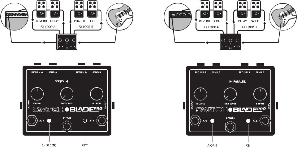
SERIES/PARALLEL Switch – This switch works in conjunction with the A/B and A+B footswitches to determine how the input signal is routed through the A and B FX loops. In SERIES mode, the FX loops are cascaded into one another with the A/B footswitch determining which FX loop is first. See Fig. 1.
Fig. 1. Series Mode
Switchblade Pro series signal flow with FX loop A selected and A+B engaged
In PARALLEL mode, the input signal is routed to the A and B FX loops simultaneously. With the A+B footswitch engaged, both signals will be mixed together at the output. With the A+B footswitch disengaged, only FX loop A or B will be engaged which is determined by the A/B footswitch. See Fig. 2.
Fig. 2. Parallel Mode
Switchblade Pro parallel signal flow with A+B engaged (A/B setting irrelevant)
If using the SWITCHBLADE PRO to switch between two amplifiers, set the SERIES/PARALLEL switch to PARALLEL in order to utilize both amps at the same time.
BYPASS FOOTSWITCH – This soft footswitch engages the SWITCHBLADE PRO, routing the signal on the INPUT jack to the SEND jacks. The signal routing is via relay and true mechanical bypass.
A/B FOOTSWITCH – This soft footswitch selects between FX loop A (RED) and FX loop B (GREEN). With the SERIES/PARALLEL switch set to SERIES mode and the A+B footswitch engaged (both FX loops on), the A/B footswitch determines which FX loop is first in the signal chain.
A+B FOOTSWITCH – This soft footswitch engages both FX loops A and B, regardless of configuration (e.g. two effects loops, two amps via the SEND jacks, two instruments via the RETURN jacks, etc.).
PHASE A & B SWITCHES – These internal slide switches allow the signals at the SEND A and SEND B jacks to be flipped 180°. This is for use with effects whose output signals are out of phase with the input signal. To access these switches, remove the four screws on the bottom of the SWITCHBLADE PRO and remove the lid. Be careful not to touch any components other than the PHASE A/B switches for danger of shocking sensitive components.

CONFIGURATIONS
The SWITCHBLADE PRO offers many different possible configurations to satisfy your various effects pedal, amp, and instrument routing needs. Here are a few examples.
SERIES EFFECTS
Shown below are two effects chains that can be used individually as clean (delay and reverb) and dirty (overdrive and phaser) sounds, but can also be used in series (FX loop B FX loop A) when engaging the A+B footswitch.
CONFIGURATIONS (cont.)
PARALLEL EFFECTS
This is an example of two effects chains that you may want to use in parallel. The synth pedal is feeding the delay in FX loop B while the compressor is feeding the reverb pedal in FX loop A. With the SERIES/PARALLEL toggle switch set to PARALLEL, each FX loop is independent and does not affect the other. The outputs of each FX loop are summed and sent to the guitar amp.
 Loading...