


OPERATOR’S MANUAL
with Illustrated Parts List
SOFT SERVE
TWIST FREEZER
Model
GES-103
184560 — 1/18
H.C. Duke & Son, LLC. |
P/N 184560 January 2018 |
Printed In U.S.A. |
|
|
|

Operator’s Manual
for the
Soft Serve Twist Freezer
Model GES-103
All contents © Copyright 2018 H.C. Duke & Son, LCC, 2116 Eighth Avenue, East Moline, Illinois 61244

Twin Twist Soft Serve Freezer Model GES-103
SAFETY FIRST!
Follow these four steps to safety ....
1. Recognize Safety Information ....Look for this safety alert symbol throughout this manual.
When you see this symbol on your freezer or in this manual, be alert to the potential for personal injury. Follow recommended precautions and safe operating practices.
2. Understand Signal Words .... |
|||||||||||||
|
|
|
|
|
|
|
|
|
|
|
The signal words — DANGER, WARNING and |
||
|
|
|
|
|
|
|
|
|
|
|
|||
|
DANGER |
CAUTION — are used with the safety alert symbol |
|||||||||||
|
(DANGER decals on the freezer may or may not |
||||||||||||
|
|
|
|
|
|
|
|
|
|
|
have the safety alert symbol, but the message is the |
||
|
|
|
|
|
|
|
|
|
|
|
same). Decals with the words DANGER, WARNING, |
||
|
|
|
|
|
|
|
|
|
|
|
or CAUTION appear on the freezer. DANGER |
||
WARNING |
identifies the most serious hazard. Decals with the |
||||||||||||
words DANGER or WARNING are typically near |
|||||||||||||
|
|
|
|
|
|
|
|
|
|
|
|||
|
|
|
|
|
|
|
|
|
|
|
specific hazards on the freezer. General precautions |
||
|
|
|
|
|
|
|
|
|
|
|
are listed on CAUTION safety decals. |
||
CAUTION |
In this manual, CAUTION messages with the safety |
||||||||||||
|
|
|
|
|
|
|
|
|
|
|
alert symbol |
call attention to safety messages. |
|
|
|
|
|
|
|
|
|
|
|
|
|||
3. Follow Safety Instructions .... |
|||||||||||||
|
|
|
|
|
|
|
|
|
|
|
Read and understand all safety messages in this |
||
|
|
|
|
|
|
|
|
|
|
|
|||
|
|
|
|
|
|
|
|
|
|
|
manual and on your freezer. Take notice of the location |
||
|
|
|
|
|
|
|
|
|
|
|
of all decals on the freezer and keep the safety decals |
||
|
|
|
|
Safety |
|
||||||||
|
|
|
|
|
in good condition. Check them periodically and replace |
||||||||
|
|
|
|
First! |
|
||||||||
|
|
|
|
|
missing, damaged, or illegible safety decals. The |
||||||||
|
|
|
|
|
|
|
|
|
|
|
|||
|
|
|
|
|
|
|
|
|
|
|
safety decals must remain in place and be legible for |
||
|
|
|
|
|
|
|
|
|
|
|
the life of the freezer. If you need new decals, use the |
||
|
|
|
|
|
|
|
|
|
|
|
|||
|
|
|
|
|
|
|
|
|
|
|
information and illustrations on pages iv and v of this |
||
|
|
|
|
|
|
|
|
|
|
|
manual to identify the decal and call or write to H.C. |
||
|
|
|
|
|
|
|
|
|
|
|
Duke & Son, LLC. |
|
|
|
|
|
|
|
|
|
|
|
|
|
|
||
|
|
|
|
|
|
|
|
|
|
|
DO NOT attempt to operate the GES-103 Twin Twist |
||
|
|
|
|
|
|
|
|
|
|
|
Soft Serve Freezer until you read and understand all |
||
|
|
|
|
|
|
|
|
|
|
|
|||
|
|
|
|
|
|
|
|
|
|
|
safety messages and the operating instructions in this |
||
|
|
|
|
|
|
|
|
|
|
|
manual. |
|
|
ii |
184560 |
Twin Twist Soft Serve Freezer Model GES-103
SAFETY FIRST!
4. Definitions ....
Trained person (or Operator): A person who has been trained in the basic operation of the freezer. This person is knowledged in operation of machine startup, stopping, filling, and basic cleaning, disassembly, washing, and sanitation of the freezer.
Freezer Technician: A person who has been trained by a factory representative, or an experienced and qualified service person, to perform more complicated operations such as freezer installation, maintenance repairs, component replacement , is aware of hazards associated with electricity, moving parts, and takes necessary steps to protect against injury to themselves and other people.
5. Operate Safely ....
IMPORTANT: Store Managers,owners, and supervisors must be aware of staff capabilities and that they do not perform freezer operations outside their level of knowledge or responsibility.
DO NOT allow untrained personnel to maintain or service this freezer. Failure to follow this instruction may result in severe personal injury. DO NOT operate the freezer until all service and access covers are
secured with screws. DO NOT attempt to repair the freezer until the main power supply has been disconnected. Some freezers have more than one disconnect switch. Contact your IDQ authorized service representative or H.C. Duke & Son, LLC Service Department for original equipment parts.
6.Caution ....
•This Freezer is to be operated by trained persons. The Dispense feature, if used by public in self-serve applications, shall be monitored by trained persons able to assist people with physical, sensory or mental
impaired capabilities.
•Children should not be allowed to play around this equipment.
•Do not store explosive substances such as aerosol cans with a flammable propellant in freezer.
•This appliance is not designed for outdoor weather conditions and shall not be exposed to rain.
•Do not wash machine with power sprayer. Do not install machine next to a power sprayer where splash of freezer can occur.
•Machine is designed for use in areas of normal atmosphere. It is not to be used in areas subject to explosion-proof standards.
184560 |
iii |

Twin Twist Soft Serve Freezer Model GES-103
Safety Decal Locations
Do not attempt to operate the freezer until all safety precautions and operating instructions in this manual are read and understood.
Take notice of all warning, caution, instruction and information decals (or labels) on the freezer as shown in the figure on the next page. The labels have been put there to help maintain a safe working environment.
The labels have been designed to withstand washing and cleaning. All labels must remain legible for the life of the freezer. Check labels periodically to be sure they can be recognized as warning labels.
If it is necessary to replace any label, please contact H.C. Duke & Son, LLC When ready to order you will need to determine the (1) part number, (2) type of label, (3) location of label, and (4) quantity required, and include a return shipping address.
For factory service assistance, contact H. C. Duke & Son, LLC, Service Department by phone or FAX:
Phone: (309) 755-4553
(800) 755-4545 FAX: (309) 755-9858
E-mail: service@hcduke.com
(The decals on the next page are numbered 1, 2, 3, and 4. Those numbers correspond to the numbers in the table below. The table provides the part number, description, and quantity for each decal.)
No. |
Part |
No. Description |
|
|
|
1...................... |
HC165025 |
...................Decal-Beater Warning (1) |
2...................... |
HC165246 .................. |
Decal-Pressurized System (3) |
3...................... |
HC165126................... |
Decal-Panel Removal Warning (1) |
4...................... |
HC165048................... |
Decal-Warning Rotating Parts (2) |
iv |
184560 |

Twin Twist Soft Serve Freezer Model GES-103
Safety Decal Locations
1 P/N HC165025
3 P/N HC165126
Hazardous rotating beater shaft. Do not operate unit with dispense head removed.
Before removing dispense head:
1. Turn all control switches to "OFF", and
2. Disconnect all power supplies. Unit may have more than one power supply.
Pressurized system. Depressurize unit
before dismantling mix transfer system.
 4 P/N HC165048 2 P/N HC165246
184560 |
v |

Twin Twist Soft Serve Freezer Model GES-103
|
Table of Contents |
|
Safety Decal Locations...................................................... |
iv |
|
1 |
Introduction................................................................ |
1 |
2 |
Note to Installer.......................................................... |
1 |
|
2.1 Uncrating and Inspection................................................ |
2 |
|
2.2 Installation...................................................................... |
3 |
|
2.3 Electrical Requirements................................................. |
3 |
|
2.4 Electrical Connections................................................... |
4 |
3 |
Specifications............................................................. |
5 |
|
3.1 Particulars...................................................................... |
5 |
|
3.2 Dimensions..................................................................... |
6 |
|
3.3 Data Plate....................................................................... |
6 |
|
3.4 Reference Information.................................................... |
7 |
|
3.5 Installation Date.............................................................. |
7 |
|
3.6 WEEE (Waste Electrical and Electronic Equipment)....... |
7 |
|
3.7 Equipment Videos........................................................... |
7 |
4 |
Virtual Quality Management System............................ |
8 |
5 |
Part Names and Functions........................................ |
10 |
6 |
Operator Controls..................................................... |
16 |
7 |
Operator Display Menus............................................ |
18 |
8 |
Disassembly and Cleaning........................................ |
22 |
|
8.1 Cleaning Accessories..................................................... |
23 |
|
8.2 Disassembly Instructions................................................ |
24 |
|
8.3 Cleaning Instructions...................................................... |
26 |
|
8.3.1 Cleaning and Lubricating - MTS Assembly........... |
29 |
9 |
Assembly.................................................................. |
30 |
10 |
Start-up Instructions................................................. |
34 |
|
10.1 Sanitizing..................................................................... |
34 |
|
10.2 Priming......................................................................... |
35 |
|
10.3 Dispensing Product...................................................... |
36 |
11 |
Closing Procedures................................................... |
37 |
|
11.1 Draining Product.......................................................... |
37 |
12 |
General Information.................................................. |
40 |
|
12.1 Dairy Queen® Mix.......................................................... |
40 |
|
12.2 Checking the Frozen DQ® Product................................ |
40 |
|
12.3 Product Temperature.................................................... |
40 |
|
12.4 Overrun........................................................................ |
41 |
|
12.5 Overrun Adjustment...................................................... |
41 |
|
12.6 Rerun........................................................................... |
42 |
|
12.7 Overrun Chart............................................................... |
42 |
13 |
Routine Maintenance................................................ |
43 |
14 |
Troubleshooting........................................................ |
49 |
|
14.1 MTS Troubleshooting Tables......................................... |
54 |
15 |
VQM Error Codes...................................................... |
56 |
vi |
184560 |

Twin Twist Soft Serve Freezer Model GES-103 |
|
Part II |
|
Replacement Parts |
|
Figure 1 Head Assembly............................................. |
1 |
Figure 2 Beater Shaft Assembly.................................. |
2 |
Figure 3 Cabinet Parts................................................ |
3 |
Figure 4 MTS—RMT Hose Assembly........................... |
4 |
Figure 5 Mix Drawer................................................... |
5 |
Figure 6 Mix Transfer System — RMT.......................... |
6 |
Figure 7 Switch Box.................................................... |
8 |
Figure 8 Spigot Switch Assemblies............................. |
10 |
Figure 9 Capacitor & Relay Box.................................. |
10 |
Figure 10 AC Side/Back View...................................... |
11 |
Figure 11 WC Side/Back View..................................... |
12 |
Figure 12 Panel Breakdown........................................ |
13 |
Figure 13 Panel Hardware & Decals............................ |
14 |
Figure 14 Gear Reducer•............................................ |
15 |
Figure 15 Evaporator Mix Tube Assembly................... |
16 |
Figure 16 Air Cooled Remote Condenser.................... |
17 |
Accessories............................................................... |
18 |
O-Ring Chart.............................................................. |
19 |
184560 |
vii |
Twin Twist Soft Serve Freezer Model GES-103
1Introduction
The GES-103 Freezer is designed to |
Be sure all personnel responsible for |
|||
produce DQ frozen soft serve ice cream |
equipment operation completely read and |
|||
or DQ yogurt, with a product serving |
understand this manual before operating |
|||
temperature of 18 to 19ºF (-8 to -7ºC). |
the freezer. When properly operated and |
|||
If such products are prepared from |
maintained, your freezer will produce a |
|||
powdered concentrate, they should |
consistent quality product. |
|||
be precooled to 40°F (4°C) prior to |
If you require technical assistance, please |
|||
introduction to the freezer. Use of other |
||||
contact your local authorized H.C. Duke & |
||||
products in this machine is considered |
||||
Son, LLC service company: |
||||
misuse (see Warranty.) |
||||
|
|
|
||
This manual has been prepared to assist |
Name ______________________ |
|||
in the training of personnel on the proper |
Address_____________________ |
|||
operation and general maintenance of |
||||
____________________________ |
||||
your Duke freezer. |
||||
Your freezer will not compensate for or |
Phone_______________________ |
|||
correct any assembly or priming errors |
or H.C. Duke & Son, LLC Service Dept. |
|||
made during the initial start-up. Therefore |
for factory service assistance. |
|||
it is extremely important to follow the |
|
Phone: (309) 755-4553 |
||
assembly and priming procedures |
|
|||
detailed in this manual. |
|
(800) 755-4545 |
||
|
|
|||
|
|
Fax number: (309) 755-9858 |
||
|
|
E-mail: |
service@hcduke.com |
|
2Note to Installer
This freezer must be installed and serviced by a service technician in accordance with the installation instructions.
After installation the warranty registration card must be completed and returned to validate warranty.
184560 |
1 |

Twin Twist Soft Serve Freezer Model GES-103
2.1Uncrating and Inspection
CAUTION |
note the damage on the carrier’s freight |
|
Be sure to properly support |
bill and notify the carrier’s local agent |
|
the machine when removing |
immediately. Also note on the freight bill |
|
bolts and installing legs or |
||
1. Remove the carton from the pallet, |
||
casters. |
||
|
and move the machine as close as |
|
When the unit is received and while |
possible to the permanent location. |
|
the carrier is still present, inspect the |
2. Remove the shipping bolts on the |
|
shipping carton for any damage that |
||
bottom of the freezer (figure 2-1) and |
||
may have occurred in transit. If the |
||
install either the legs or casters (figure |
||
SHOCKWATCH® label indicates red and/ |
||
2-2). |
||
or the carton is broken, torn, or punctured |
||
|
Figure 2-1 Machine bolted to Shipping Base
|
REAR |
|
OF UNIT |
|
CASTER |
CASTER |
WITHOUT |
WITH BRAKE |
BRAKE |
|
NOTE: Screw casters or |
|
legs all the way in coupling, |
Figure 2-2 Installing Mounting Legs or Casters |
then adjust out to level side |
to side with 1/4 inc (6mm) |
|
|
slope to the front. |
— continued
2 |
184560 |

Twin Twist Soft Serve Freezer Model GES-103
2.2Installation
CAUTION |
|
not subjected to hot exhaust air from |
|
|
other equipment. Anything blocking |
||
All materials and connections |
|
||
must conform to local |
|
ventilation, (e.g. cone dispenser), will |
|
requirements and be in |
|
reduce the efficiency of the freezer. |
|
compliance with the National |
4. |
Water cooled double models will |
|
Electrical Code (NEC). |
|||
|
|
require a 1/2” MPT water inlet and |
|
1. This freezer is designed for indoor use |
|
water waste connection. Both water |
|
|
condensers are tied together so that |
||
and must be protected from outdoor |
|
one water inlet and one water waste |
|
weather conditions. |
|
is all that is required. The connections |
|
2. Where codes permit, we recommend |
|
are found on the bottom under the |
|
|
compressor mounting area and are |
||
that the freezer be installed on casters |
|
||
|
clearly tagged - “Water Inlet” and |
||
and have flexible water and electrical |
|
||
|
“Water Waste”. A manual shut-off |
||
connections for service and cleaning |
|
||
|
valve should be installed in the water |
||
ability. |
|
||
|
inlet line at the time of installation. |
||
|
|
||
IMPORTANT: |
|
The water pressure must be between |
|
|
35-140 psig (241-965kPa) for proper |
||
Unit requires air ventilation. The |
|
||
|
operation. |
||
minimum air space at the sides must |
|
||
|
|
||
be 6 inches (15.2cm) and 1 in.(2.5cm) |
5. Place the freezer in the final location |
||
in the rear or 6 inches in the rear and |
|||
|
and level the machine by adjusting |
||
1 inch on the sides. Top must have |
|
||
|
the legs or casters so that the unit |
||
29 inches clearance. Failure to follow |
|
||
|
is level side-to-side, and the front |
||
minimum air clearances will void |
|
||
|
is approximately ¼” lower than the |
||
warranty. |
|
||
|
rear, to allow proper drainage of the |
||
|
|
||
|
|
freezing cylinder. |
|
3. All models require 6 inches (15.3 cm) |
6. |
Water Cooled Do not allow freezer to |
|
minimum air space at rear, 1in(2.54 |
|||
|
be in ambient where air temperature |
||
cm) on sides or 6 inch (15.3 cm) on |
|
||
|
goes below 0°C (32°F),the freezing |
||
each side and 1inch (2.54cm) at rear. |
|
||
|
temperature of water. |
||
Space above freezer is to be 29 inch |
|
||
|
|
||
(79.7 cm) and is to be provided with |
7. |
Water consumption increases if |
|
an 6 in (15.3 cm) air deflector at rear |
|
temperature of entering water is |
|
if boxed on 3 sides. Insure freezer is |
|
above 20°C (65°F) |
|
2.3 |
ElectricalRequirements |
|
|
|
|
|
|
|
|
|
|
CAUTION |
2. Supply voltage must be within + 10% |
|
|
|
To prevent accidental |
of voltage indicated on the nameplate. |
|
|
|
electrical shock, a positive |
Also, on three-phase systems, |
|
|
|
earth ground is required. |
voltage between phases must be |
|
|
|
|
balanced within 2%. (More than a |
|
|
|
|
6 volt difference between any two |
|
|
|
1. Always verify electrical specifications |
voltage measurements at 208-230 |
|
|
|
volts indicates a possible imbalance.) |
||
|
|
on the data plate of each individual |
Request your local power company to |
|
|
|
freezer. Data plate specifications will |
correct any voltage problem. |
|
|
|
always supersede the information in |
3. An easily accessible main power |
|
|
|
this manual. (See Figure 3-2) |
||
|
|
|
disconnect must be provided for all |
|
|
|
|
poles of the wiring to the freezer. |
|
184560 |
3 |
Twin Twist Soft Serve Freezer Model GES-103
2.4ElectricalConnections
CAUTION |
4. Electrical connections are made in |
|
the junction boxes located mid-level |
||
To prevent accidental |
||
behind the right side panel. |
||
electrical shock, a positive |
||
|
||
earth ground is required. |
Important |
|
|
||
|
Set switch next to the connection |
|
Important! |
box “UP” for 220-230v or “DOWN” |
|
for 208-219V. Failure to set switch to |
||
A positive earth ground is required |
||
proper voltage will cause damage to |
||
for electronic VQM system to operate |
||
the electrical components and will void |
||
correctly. |
||
all warranties. |
||
|
||
1. Double freezers with two compressors |
5. Use a flexible connection when |
|
require one power supply for each |
||
permissible. |
||
side of the freezer. Each side of the |
||
|
||
freezer operates independently. |
6. Beater Shaft Rotation Freezers are |
|
|
||
2. Check the data plate for fuse |
designed for clockwise rotation when |
|
viewed from front of freezer. 1ph |
||
size, wire ampacity, and electrical |
||
machines are prewired for proper |
||
specifications. (See Figure 3-2) |
||
rotation. On 3 phase machines, |
||
|
||
3. Refer to the wiring diagram provided |
phase wires to freezer should be |
|
for proper power connections. |
connected to produce proper beater |
|
|
rotation. This is to be done by a |
|
|
freezer technician. |
WARNING
Warning: When installing the machine, insert an all pole disconnect, adequately sized according to freezer nameplate marking with electrical contact spacing of 3mm minimum. This should be within sight of the freezer.
4 |
184560 |

Twin Twist Soft Serve Freezer Model GES-103
3Specifications
3.1Particulars
Always check and verify voltage and amperage on the data plate located on the back panel of each freezer.
GES-103 |
|
|
|
Width-in./cm |
26.125/66.36 |
|
|
Height-in./cm |
69.875/177.48 |
|
|
Depth-in./cm |
38.25/97.16 |
|
|
Weight-lbs./kg |
850/386 |
|
|
Compressor (2) |
2.5 H.P. /19000 BTUH |
||
|
2.2 |
kw |
(Motor) |
|
3.2 |
kw |
(Cooling) |
Compressor Cabinet (1) |
1/6HP/1000BTUH |
|
|
|
125w |
(Motor) |
|
|
190w |
(Cooling) |
|
Beater Motor (2) |
2 H.P/1.5 |
kw |
|
Refrigerant |
404a |
|
|
Charge* |
3.75 lb/1.7 kg |
|
|
Mix Capacity |
6 - 5gal. Bags |
|
|
Cylinder (2) |
5 Qts./4.7 Liters |
|
|
ACR |
|
|
|
Noise: The Steady acoustic pressure level, for both air cooled and water cooled freezers, is less than 70dB(A).
Water Cooled units: Water consumption increases if temperature of entering water is above 20°C (65°F)
*Approximate for each side. See nameplate for actual charge.
184560 |
5 |

Twin Twist Soft Serve Freezer Model GES-103
3.2Dimensions
The dimensions of the GES-103 are provided in Figure 3-1, below.
26.125" |
|
|
38.25" |
|
|
||
|
|
|
|||||
|
|
|
97.16 cm |
|
|
||
|
66.36 cm |
|
|
AIR OUT |
|
||
TOP OF UNIT MUST BE KEPT |
|
|
|||||
CLEAR TO ALLOW AIR EXHAUST |
|
|
|
|
|
||
ELECTRICAL SERVICE CONNECTION
65.5" 166.37 cm
69.875" 177.48 cm
AIR IN |
AIR IN |
AIR IN |
IN OUT
1/2 FPT WATER IN/OUT |
4.3125" |
ALL CONNECTIONS ARE MADE |
(WATER COOLED ONLY) |
10.95 cm |
THROUGH BOTTOM OF FREEZER |
Figure 3-1
3.3 Data Plate
1 |
2 |
3 |
The data plate provides important information that the operator should record and have available for parts ordering, warranty inquiries, and service requests.
 5
5  4
4
Figure 3-2 Data Plate
6 |
184560 |

Twin Twist Soft Serve Freezer Model GES-103
3.4ReferenceInformation
Write in
Reference
Information HERE!
Fill in the following information below as soon as you receive the GES-103. (The item numbers—encircled, below— correspond with the callout numbers above.)
|
IMPORTANT: Complete for reference: |
|
1.) Model Number: _________________ |
||
|
||
|
2.) Serial Number: _________________ |
|
|
3.) Electrical Spec: Voltage___________ |
|
|
Phase _______ Hertz____________ |
|
|
4.) Maximum Fuse Size:_____________ |
|
|
5.) Minimum Circuit Ampacity:_________ |
3.5InstallationDate
Installation Date_______________________
Installed by___________________________
Address ___________________________
___________________________
Phone ___________________________
3.6WEEE (Waste Electrical and Electronic Equipment)
In conformity with EU 2002/96/EC, this freezer, at the end of life cycle, is not to be discarded with normal urban waste. Instead, it is the user’s
responsibility to dispose of this product by returning it to a collection point designated for the recycling of electrical, electronic components and separation of reclaimable, recyclable materials. Contact your local distributor or authority for correct disposal.
3.7EquipmentVideos
To view videos on setting up and priming the GES freezer visit:
http://www.electrofreeze.com/GES_Videos.aspx
184560 |
7 |

Twin Twist Soft Serve Freezer Model GES-103
4Virtual Quality Management System (VQM) Terminology
Beater Run: |
This D.O.B. timer used to delay the beater motor after |
|
the refrigeration shuts down. Beater Run Range: 0 to 10 |
|
seconds |
Demand Run Comp: The D.O.B. timer used to delay the compressor when product is being drawn. Demand Run Comp. Range: 0 to 12 seconds
Differential/ Hyst: Symbolizes the differential setting. Differential range: 7 to 20°F i.e. if your cut in is at 18°F and your Differential is at 10°F your unit will cut out at 8°F
Dual Diff: The differential used when product is being drawn out of the center spigot. Dual Differential range: 7 to 20°F
Idle: When the unit is cycling on temperature and no product is being dispensed
Idle Run Comp: Delay on break (D.O.B.) timer used for the compressor when the unit is in idle mode/no product being drawn. Idle Run Comp. Range: 0 to 20 seconds
Lock outs: Allows the function of a specific feature/button to be temporarily disabled to deter un-necessary usage of that feature.
Main P.C. Board: Main Control board for the unit, housed behind the trim strip panel. This board has many connectors on it and is responsible for the main operations of the unit.
Membrane Switch: The black Electro Freeze decal visible on the front of the unit, which houses the hidden operator, technician, soft, and hard keys used to navigate the menus
Relay Board A control board located in the main electrical control box. This Board contains no software, only solid state control relays to operate system components.
Single Diff: The differential used when product is being drawn out of one barrel. Single Hysteresis range: 7 to 20°F
8 |
184560 |

Twin Twist Soft Serve Freezer Model GES-103
4Virtual Quality Management System (VQM) Terminology (continued)
Slope/Demand Slope: Utilizes a function within the system to watch the temperature change as the unit freezes a barrel. If utilizing the slope feature and the unit sees a lack of temperature change during freeze down, the unit will cycle off. This will prevent a freeze up condition due to a long run time. Demand Slope range: 0 to -0.2
Temp. Comp.: Temperature compensation, utilized when the slope feature is turned on. It prevents the system from seeing the
slope temperature curve until a determined temperature is reached. Once that temperature has been reached then the system will examine the curve and shut down if
necessary. Temp. Comp. Range: -10 to 22°F
Temperature Offset: A function that allows temperature adjustment to the operator. Adjustable from 1-9 and 5 being neutral/no change, Lower than 5= colder and greater than 5=warmer
Transducer: An electronic control used to measure the cylinder pressure for mix pump operation.
U.I./ User Interface: The board that lies directly behind the membrane switch on the front panel. This board houses the LED screen that displays the menus and operations. The membrane switch is connected to this board via a ribbon cable. This board also has its own software.
184560 |
9 |
Twin Twist Soft Serve Freezer Model GES-103
5Part Names and Functions
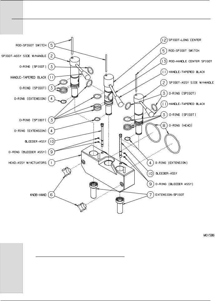
Figure 5-1 Head Assembly
10 |
184560 |
Twin Twist Soft Serve Freezer Model GES-103
5Part Names and Functions (continued)
The following descriptions apply to figure 5-1. The number preceding the part name corresponds to the number in the figure.
1.) |
HEAD: |
10.) |
PLUG-AIR BLEED (BLEEDER |
|
|
Encloses the freezing cylinder and |
|
ASSY.): |
|
|
provides an opening for product to be |
|
Seals the air bleed opening in the |
|
|
dispensed. NOTE: Beater motors will |
|
head when closed. Allows excess |
|
|
not operate with the head removed |
|
air to be removed from the cylinder |
|
|
from the freezer. |
|
when priming. |
|
2.) |
SPIGOT - ASSEMBLY SIDE WITH |
11.) |
HANDLE-TAPERED BLACK |
|
|
HANDLE (STAINLESS STEEL): |
|
(PLASTIC): |
|
|
Seals the product opening in the head |
|
Black plastic handle that fits onto |
|
|
when closed. Allows product to flow |
|
the stainless steel handle. |
|
|
when open. |
12.) SPIGOT-LONG CENTER |
||
|
|
|||
3.) |
O-RING - SPIGOT: |
|
WITHOUT HANDLE (STAINLESS |
|
|
Seals the spigot in the head. Must be |
|
STEEL): |
|
|
lubricated to seal and slide properly. |
|
Seals the product opening in the |
|
4.) |
O-RING - SPIGOT EXTENSION: |
|
dispense head when closed. Allows |
|
|
product to flow when open. |
|||
|
Holds the extension on to the spigot. |
13.) ROD-HANDLE CENTER SPIGOT |
||
5.) |
ROD - SPIGOT: |
|||
|
(STAINLESS STEEL): |
|||
|
Starts the freezer when dispensing. |
|
Opens and closes the spigot to |
|
|
Must be in place before freezer will |
|
start and stop the flow of product |
|
|
operate. |
|
from the freezer. |
|
6.) |
KNOB-HAND: |
|
|
|
|
Secures the head to the freezing |
|
|
|
|
cylinder. |
|
|
|
7.) |
EXTENSION - SPIGOT: |
|
|
|
|
(ACCESSORY) |
|
|
|
|
Extends the product opening down to |
|
|
|
|
shape the product as it is dispensed. |
|
|
|
8.) |
O-RING - HEAD: |
|
|
|
|
Seals the head to the freezing |
|
|
|
|
cylinder. Must be lubricated. |
|
|
|
9.) |
O-RING-AIR BLEED PLUG: |
|
|
|
|
Seals the air bleed plug in the head. |
|
|
|
184560 |
11 |
Twin Twist Soft Serve Freezer Model GES-103
5Part Names and Functions (continued)
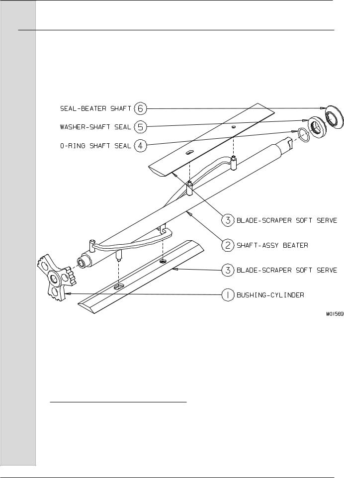
Figure 5-2 Beater Shaft Assembly
12 |
184560 |

Twin Twist Soft Serve Freezer Model GES-103
5Part Names and Functions (continued)
The following descriptions apply to figure 5-2. The number preceding the part name corresponds to the number in the figure.
1.) |
BUSHING - CYLINDER: |
5.) |
WASHER - SHAFT SEAL: |
|
Holds the beater in place at the front |
|
Holds the shaft seal o-ring. Lightly |
|
of the cylinder. |
|
lubricate the side opposite the cup |
2.) |
SHAFT - BEATER: |
|
seal. |
|
|
||
|
Rotates in the freezing cylinder, |
6.) |
SEAL(CUP) - BEATER SHAFT: |
|
blending air and mix as it ejects |
|
Seals the opening between the |
|
product. |
|
freezing cylinder and the beater |
3.) |
BLADE - SCRAPER: |
|
shaft. Do not lubricate rubber cup |
|
portion. |
||
|
Scrapes the frozen product from the |
|
|
|
|
|
|
|
freezing cylinder wall |
|
|
4.) |
O-RING - SHAFT SEAL: |
|
|
|
Seals the beater shaft to the shaft |
|
|
|
seal. Is inserted into the shaft seal |
|
|
|
washer. Must be lubricated. |
|
|
184560 |
13 |

Twin Twist Soft Serve Freezer Model GES-103
5Part Names and Functions (continued)
|
|
RETAINER-AIR LINE |
CLAMP-SOFT HOSE |
|
|
AIR TUBE |
8 |
6 |
9 |
|
|
|
||
11 |
AIR METER |
7 |
|
|
|
|
|
|
|
COVER-MTS
MIX FLOW
PORT-AIR/MIX INLET |
HOSE-ASSY MIX BRAIDED |
15 |
10 |
MIX |
FLOW |
|
MIX |
FLOW |
|
AIR CURTAINSWITCH |
20 |
|
|
|
ARM-SWING CLAMP |
5 |
FLOW |
FLOW |
|
SHOE-SPRING |
18 |
|||
MIX |
MIX |
|||
|
|
|||
KNOB-HAND |
4 |
|
|
|
MIX DRAWER |
19 |
|
|
21 |
AIR CURTAIN |
|
|
|
|
|
17 |
14 |
16 |
|
|
CLAMP-RATCHET |
DUCKBILL-INLET |
ADAPTER-MIX BAG |
Figure 5-3 Mix Transfer System (MTS)
11
COVER-MTS
12 |
HOSE-TRANSFER RED LINE |
1 |
SUPPORT-ROLLER BEARING |
2 |
ROLLER SHOE |
3 |
ROLLER-ASSY COMPLETE |
13 TUBE-MIX INLET
M02079rev4
14 |
184560 |

Twin Twist Soft Serve Freezer Model GES-103
5Part Names and Functions (continued)
The following descriptions apply to figure 5-3. The number preceding the part name corresponds to the number in the figure.
1.) |
SUPPORT - ROLLER BEARING: |
13.) |
TUBE - ASSEMBLY MIX INLET: |
|
|
Holds roller assembly in place. |
|
Carries mix from mix container to |
|
2.) |
SHOE - ROLLER: |
|
MTS. |
|
14.) |
DUCKBILL: |
|||
|
Provides an opening to insert the |
|||
|
mix transfer hose. Squeezes transfer |
|
A rubber check valve that prevents |
|
|
hose against rollers. |
|
mix from falling back into the mix |
|
3.) |
ROLLER ASSEMBLY COMPLETE: |
|
container. |
|
15.) |
PORT - AIR/MIX: |
|||
|
Squeezes mix/air through tubing to |
|||
|
freezing cylinder. |
|
Blends air and mix as it flows into the |
|
4.) |
KNOB - HAND: |
|
transfer hose. |
|
16.) |
ADAPTER - MIX BAG: |
|||
|
Locks roller shoe in position. |
|||
5.) |
ARM - SWING CLAMP: |
|
Connects the mix inlet tube to the |
|
|
mix bag. |
|||
|
Swings hand knob into position over |
17.) |
CLAMP-HOSE RATCHET: |
|
|
roller shoe. |
|||
6.) |
RETAINER - AIR TUBE: |
|
Plastic clamp for connecting bag |
|
|
adapters to hose. |
|||
|
Holds air meter tube in the “up” |
18.) |
SHOE - SPRING: |
|
|
position. |
|||
7.) |
AIR METER: |
|
Holds clamp in place. |
|
19.) |
MIX DRAWER: |
|||
|
Regulates the amount of air being |
|||
|
drawn into the system. |
|
Storage area for mix bags. |
|
8.) |
TUBE - AIR: |
20.) |
AIR CURTAIN SWITCH: |
|
|
Provides connection for the air |
|
Detects if air curtain is in position for |
|
|
meter. |
|
cleaning. |
|
9.) |
CLAMP - ASSY. SOFT HOSE 5/8”: |
21.) |
AIR CURTAIN: |
|
|
Prevents mating parts from leaking. |
|
Located inside cabinet door. Used |
|
10.) |
HOSE - ASSY. MIX BRAIDED: |
|
when cleaning MTS pumps with mix |
|
|
in shelves. Automatically refrigerates |
|||
|
Connecting tube between the Mix |
|
cabinet when positioned in front of |
|
|
Transfer System and the cylinder |
|
shelves. |
|
|
inlet. |
|
|
|
11.) |
COVER - MTS: |
|
|
|
|
Protection against moving parts. |
|
|
|
|
Cover must be in place for the MTS |
|
|
|
|
to operate. |
|
|
|
12.) |
HOSE - TRANSFER RED: |
|
|
|
|
Special “red-lined” hose that is |
|
|
|
|
squeezed by rollers to transfer mix to |
|
|
|
|
freezer. |
|
|
184560 |
15 |
Twin Twist Soft Serve Freezer Model GES-103
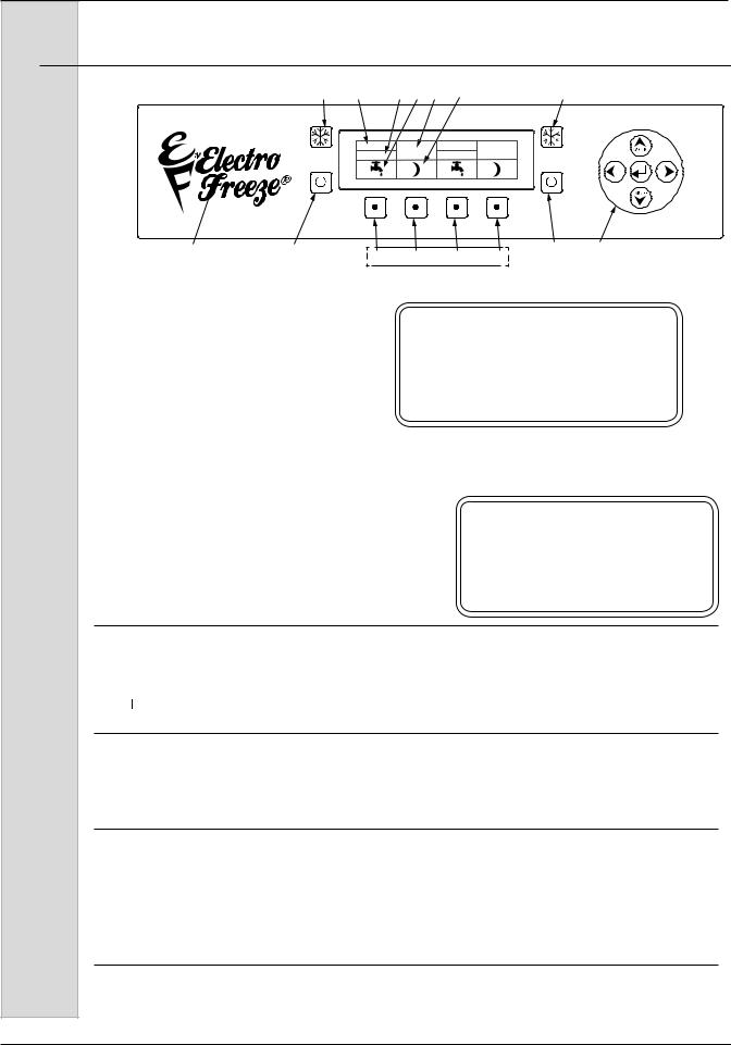
6Operator Controls
4 |
5 |
6 |
7 |
8 |
9 |
4 |
|
LEFT |
|
|
|
RIGHT |
|
|
OFF |
|
|
|
OFF |
|
|
Figure 6-1 10 |
2 |
|
|
|
|
|
|
|
3 |
|
|
L1 |
L2 |
R1 |
R2 |
2 |
||||
|
|
|
|
|
1 |
|
|
|
|
|
The following paragraphs describe the |
|
|
CAUTION |
|
||||||
|
|
|
|
|||||||
operator controls. Refer to Fig. 6-1 for |
|
|
|
|
||||||
numbered items in description. |
|
Note the |
|
|
Test operation of the head |
|||||
left side controls operates the left side |
|
|
switch prior to placing the |
|||||||
|
|
freezer in service. See Section |
||||||||
cylinder and hopper. Operation for right |
|
|
||||||||
|
|
11, Routine Maintenance, |
||||||||
side controls is the same. The display |
|
|
||||||||
|
|
Monthly. |
|
|||||||
window has three levels of display: |
|
|
|
|||||||
|
|
|
|
|
|
|||||
Operators Menu, Technician Menu, and |
|
|
|
|
|
|
||||
Factory Menu. The last two menus |
NOTE: The dispense head must be in |
|||||||||
are restricted and reserved for use by |
||||||||||
qualified personnel. |
|
|
|
place before the freezer will operate. |
||||||
|
|
|
|
|
|
|
|
IMPORTANT |
||
To view videos on the GES freezer visit: |
|
|
DISPENSING HEAD MUST BE |
|||||||
http://www.electrofreeze.com/GES_Videos.aspx |
|
INSTALLED FOR BEATER |
||||||||
|
MOTOR(S) TO OPERATE. |
|||||||||
DO NOT INTERCHANGE HEADS FROM OTHER FREEZERS.
1. Function Buttons (Four)
Pressing any of these buttons will activate the icon directly above in the display screen. Left side (L1 & L2), Right Side (R1& R2).
2.  OFF Key
When this symbol is pressed, the left side of unit will shut off. The beater motor and compressor will not operate.
3. Navigation Pad (Up/Down = Cabinet ON/OFF)
Used to navigate the menu structure as well as turning the cabinet on/off.
UP Arrow - Energizes Cabinet refrigeration only when freezer is in OFF position. DWN Arrow - De-energizes Cabinet refrigeration only when CAB Refrig is ON. See Troubleshooting section for Operator accessible controls.
4.  Freeze Symbol
When this symbol is pressed, the unit will enter the automatic freeze mode. Both the hopper and cylinder compressors will energize to refrigerate product to settings in program. Use this button for DAY mode operation to maintain product in “ready to serve” state.
16 |
184560 |

Twin Twist Soft Serve Freezer Model GES-103
6Operator Controls (continued)
5. Left or Right side Control Indicator
Left indicates controls for left side cylinder and hopper. “Right” Indicates controls for right side of freezer cylinder and hopper.
6. Mode of Operation Indicator
There are three primary modes of operation:
a.OFF –This is the indicator when power is applied to freezer and when (OFF) button is pressed. In this mode, the refrigeration and beater motor will not operate.
b.FRZ – This is the indicator when Freeze button is pressed. In this mode, the freezer is in automatic freeze mode and both the beater motor and refrigeration will activate as needed. Use this position for dispensing product from freezer. Hopper will also be refrigerated as needed to maintain product below 41°F.
Important: Do not use the  freeze position with water or sanitizer in the cylinder or hopper. The freezer will be damaged.
c. Night – This is the indicator when Night button is pressed. In this mode, an energy-saving feature will activate and reduce product refrigeration. The freezer will automatically cycle to maintain temperatures in the cylinder and hopper below 41°F and keep product from deteriorating. Use this position when the freezer will not be in use for periods of more than one hour.
7.  Wash or Clean Mode
Press the function button directly below icon to activate clean mode.
8. Information Window
This window is normally blank when unit is functioning properly. This window will give you indication when mix in hopper is low and other error messages. Refer to Troubleshooting Section of manual for details on error messages.
9. Night Mode Operation
As pictured, the Soft Key located below the image of the Moon will allow the machine to be switched into NIGHT refrigeration mode. This feature is used at the closing of the day’s business to hold the product at safe storage temperatures but not in a frozen state.
10. Hidden Operator Menu Key
Press this key to enter the operator menu to adjust the freezers settings.
184560 |
17 |

Twin Twist Soft Serve Freezer Model GES-103
6Operator Controls (continued)
12 Power Switch See Figure 6-3
In the “ON” position, power is supplied to the beater motors. Use this position to operate the freezer. Select the ”OFF” position for disassembly and cleaning. See Operators Display Menu for use of this switch in recording cleaning cycles.
Figure 6-3
7Operator Display Menus
4 |
5 |
6 |
7 |
8 |
9 |
4 |
|
LEFT |
|
|
|
RIGHT |
|
|
OFF |
|
|
|
OFF |
|
10 |
2 |
|
|
|
|
|
|
|
3 |
|
L1 |
L2 |
R1 |
R2 |
2 |
||||
|
|
|
|
|
|
||||
Figure 7-1 |
|
|
|
|
1 |
|
|
|
|
|
|
|
|
|
|
|
|
|
|
To Enter the Operator Menu, push and hold the hidden key (11) under the F for 3 seconds (figure 7-1).
Figure 7-2
The operator menu will show up on the screen (figure 7-2). The cursor will highlight the selected sub-menu (i.e. Basic Setting, Actual Temps, etc.), use the Arrow Buttons to move the cursor up or down to the desired sub-menu. Once the desired menu is highlighted, in
this example we will use Basic Settings, press the select ( ) button to enter the sub-menu. Product Type and Temperature Offset will be shown for left and right barrel. Use the Arrow Buttons to move the cursor to highlight the value to be changed, once highlighted press the select button and the cursor will now be blinking. While the cursor is blinking the value may now be changed using the left or right Arrow Buttons, once you have reached the desired
setting press select ( ) one more time, the cursor will now stop blinking, this indicates that the value change has been stored. Follow these steps to change any other desired settings, once complete you may use the far right Function button to exit the operator menu or just wait
and the menu will time out and return to the Home screen.
18 |
184560 |

Twin Twist Soft Serve Freezer Model GES-103
7Operator Display Menus (continued)
Below is a list of the menu categories that are displayed upon entering the
Operator’s menu.
Operator’s Menu Options
•Basic Settings
•Actual Temps
•Event Log
•Error Log
•Lockouts
•Screen Settings
•Date/Time
•Last Clean
•Software Version
The following information explains more about each of the menu options.
Basic Settings: |
Information Shown |
|
|
|
Product Type: |
Alt 1 (Preset for DQ Product) |
|
|
Temperature Offset 1-9 |
5 |
is Neutral |
|
Cabinet Temp. |
6 |
is Default setting |
Actual Temps: |
Information Shown |
|
|
Cabinet Temperature |
|
|
Cylinder Temperature: Left or Right Cylinder |
|
Event Log: Allows the operator to look at logged events i.e. power switch cycle, low mix, etc. The log will display the last 50 events with the newest event at the top.
Error Log: Allows the operator to look at logged errors i.e. Barrel refrigeration timeout, low/high refrigeration pressure, etc. The log will display the last 50 events with the newest event at the top.
Statistics: Shows the number of starts that the compressor/compressors, switches and beater motors have seen. Also displays the cumulative run time in hours for compressors and beater motors.
Information Shown |
|
|
|
|
On Time |
Left & Right Barrel |
|
|
|
Freeze Mode |
Left & Right Barrel |
|
|
|
Standby Mode |
Left & Right Barrel |
|
|
|
Off |
Left |
& |
Right |
Barrel |
Last PWR Fail |
|
|
|
|
All PWR Fail Time |
|
|
|
|
All PWR Fails |
|
|
|
|
Spigot |
Left |
& |
Right |
Barrel |
184560 |
19 |

Twin Twist Soft Serve Freezer Model GES-103
7Operator Display Menus (continued)
Statistics Cont.
Center Spigot |
|
Spigot Hours |
Left & Right Barrel |
C Spigot Hours |
|
Comp. Starts |
Left & Right Barrel |
Comp. Hours |
Left & Right Barrel |
Beater Starts |
Left & Right Barrel |
Beater Hours |
Left & Right Barrel |
Cab Comp. Starts |
|
Cab Comp. Hours |
|
Pump Starts |
Left & Right Barrel |
Pump Hours |
Left & Right Barrel |
Lockouts: Allows the operator to lock out the clean, freeze, and night function so that on the home screen when the button is pressed the unit will not react.
Information Shown |
|
Y or N |
Freeze Mode |
|
|
Clean Mode |
|
Y or N |
Standby Mode |
Y or N |
|
Cab Only Mode |
Y or N |
|
Cones |
Left |
5 |
Screen Settings: Operator can turn on or off the following functions:
Display Cabinet TemperatureY or N
(Will or will not display Cabinet temp. on home screen)
Alternate Moon |
Y or N |
Beep Function |
Y or N |
(unit will or will not beep when a button is pressed) Hide Clock Error Y or N
Date/Time: Allows user to set the Real Time Clock and current date in the unit.
Last Clean: Displays the Last time the unit has been cleaned
Software Versions: Has current software version numbers for both the U.I. and
Main board |
|
|
|
|
Main ——— |
|
|
|
|
U.I. ———— |
|
|
|
|
Model |
|
GES |
|
|
Cyl |
Count |
2 |
|
|
Compressors |
2 |
|
|
|
Hopper |
|
Y |
or |
N |
Cabinet |
|
Y |
or |
N |
Product |
Table |
GES |
or |
SLX |
Cabinet Temperature Map for user adjustment. User will only see 1 through 9 but the table below shows the differences with each number change. 6 is default setting
20 |
184560 |
 Loading...