

ELECTRO FREEZE COMPACT Series, CS705-M2 Operator's Manual
OPERATOR’S MANUAL
with Illustrated Parts List
COMPACT SERIES
SHAKE FREEZER
Model CS705-M2
184592-01 - 7/17
H. C. Duke & Son, LLC P/N 184592-01 - July 2017 Printed in U.S.A.


Operator’s Manual
for the
Electro Freeze Model CS705-M2
Compact Series
Soft Serve Freezer
All contents © Copyright 2016 H.C. Duke & Son, LLC, 2116 Eighth Avenue, East Moline, Illinois 61244
i
ELECTRO FREEZE Shake Model CS705-M2
SAFETY FIRST!
Follow these four steps to safety ....
1. Recognize Safety Information ....Look for this
safety alert symbol throughout this manual.
When you see this symbol on your freezer or in this
manual, be alert to the potential for personal injury. Follow
recommended precautions and safe operating practices.
2. Understand Signal Words ....
The signal words — DANGER, WARNING and CAUTION —
DANGER
WARNING
CAUTION
are used with the safety alert symbol (DANGER decals on
the freezer may or may not have the safety alert symbol, but
the message is the same). Decals with the words DANGER,
WARNING or CAUTION appear on the freezer. DANGER
identies the most serious hazard. Decals with the words
DANGER or WARNING are typically near specic hazards
on the freezer. General precautions are listed on CAUTION
safety decals.
In this manual, CAUTION messages with the safety
alert symbol
call attention to safety messages.
3. Follow Safety Instructions ....
Read and understand all safety messages in this manual.
Read and understand the decal safety messages on your
freezer. Take notice of the location of all decals on the
freezer and keep the safety decals in good condition. Check
them periodically and replace missing, damaged or illegible
safety decals. The safety decals must remain in place and
legible for the life of the freezer. If you need new decals, use
the information and illustrations on pages iv and v of this
manual to identify the decal and order replacement parts.
DO NOT attempt to operate the CS705-M2 freezer until you
read and understand all safety messages and the operating
instructions in this manual.
184592-01ii
ELECTRO FREEZE Shake Model CS705-M2
SAFETY FIRST!
4. Definitions ....
Trained person (or Operator): A person who has been trained in the basic operation of
the freezer. This person is knowledgeable in the operation of machine startup, stopping,
lling, and basic cleaning, disassembly, washing, and sanitation of the freezer.
Freezer Technician: A person who has been trained by a factory representative, or
an experienced and qualied service person, to perform more complicated operations
such as freezer installation, maintenance repairs, component replacement , is aware of
hazards associated with electricity, moving parts, and takes necessary steps to protect
against injury to themselves and other people.
5. Operate Safely ....
IMPORTANT: Store Managers,owners, and supervisors must be aware of staff
capabilities and that they do not perform freezer operations outside their level of
knowledge or responsibility.
DO NOT allow untrained personnel to maintain or service
this machine. Failure to follow this instruction may result in
severe personal injury. DO NOT operate the freezer unless
all service panels and access doors are secured with screws.
DO NOT attempt to maintain or repair the freezer until the
main power supply has been disconnected. Contact your
local Electro Freeze Distributor for authorized service.
6. Caution ....
• This Freezer is to be operated by trained persons. The Dispense
feature, if used by public in self-serve applications, shall be monitored
by trained persons able to assist people with physical, sensory or mental
impaired capabilities.
• Children should not be allowed to play around this equipment.
• Do not store explosive substances such as aerosol cans with a ammable propellant
in freezer.
• This appliance is not designed for outdoor weather conditions and shall not be
exposed to rain.
• Do not wash machine with power sprayer. Do not install machine next to a power
sprayer where splash of freezer can occur.
• Machine is designed for use in areas of normal atmosphere. It is not to be used in
areas subject to explosion-proof standards.
184592-01 iii
ELECTRO FREEZE Shake Model CS705-M2
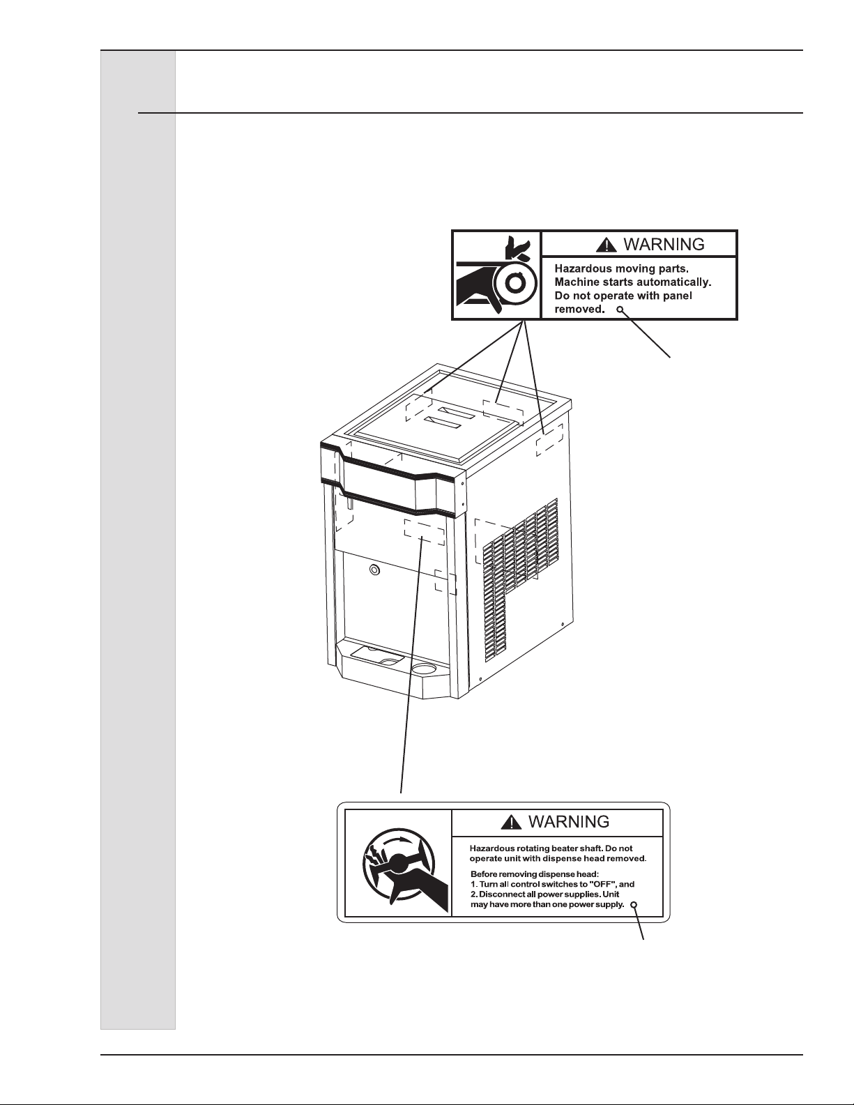
Safety Decal Locations
Do not attempt to operate the freezer
until all safety precautions and operating
instructions in this manual are read and
understood.
Take notice of all warning, caution,
instruction and information decals (or
labels) on the freezer as shown in the
gure on the following page. The labels
have been put there to help maintain a
safe working environment.
The labels have been designed to
withstand washing and cleaning. All
labels must remain legible for the life of
the freezer. Check labels periodically
to be sure they can be recognized as
warning labels.
If it is necessary to replace any label,
please contact your local authorized
Electro Freeze Distributor or H. C. Duke &
Son. When ready to order you will need to
determine the (1) part number, (2) type of
label, (3) location of label, and (4) quantity
required, and include a return shipping
address.
You may contact your local authorized
Electro Freeze Distributor, as follows:
Name:
Address:
Phone:
or — for factory service assistance —
contact H. C. Duke & Son, LLC. Electro
Freeze Service Department by phone or
FAX:
Phone: 309-755-4553
800-755-4545
FAX: 309-755-9858
E-mail: service@electrofreeze.com
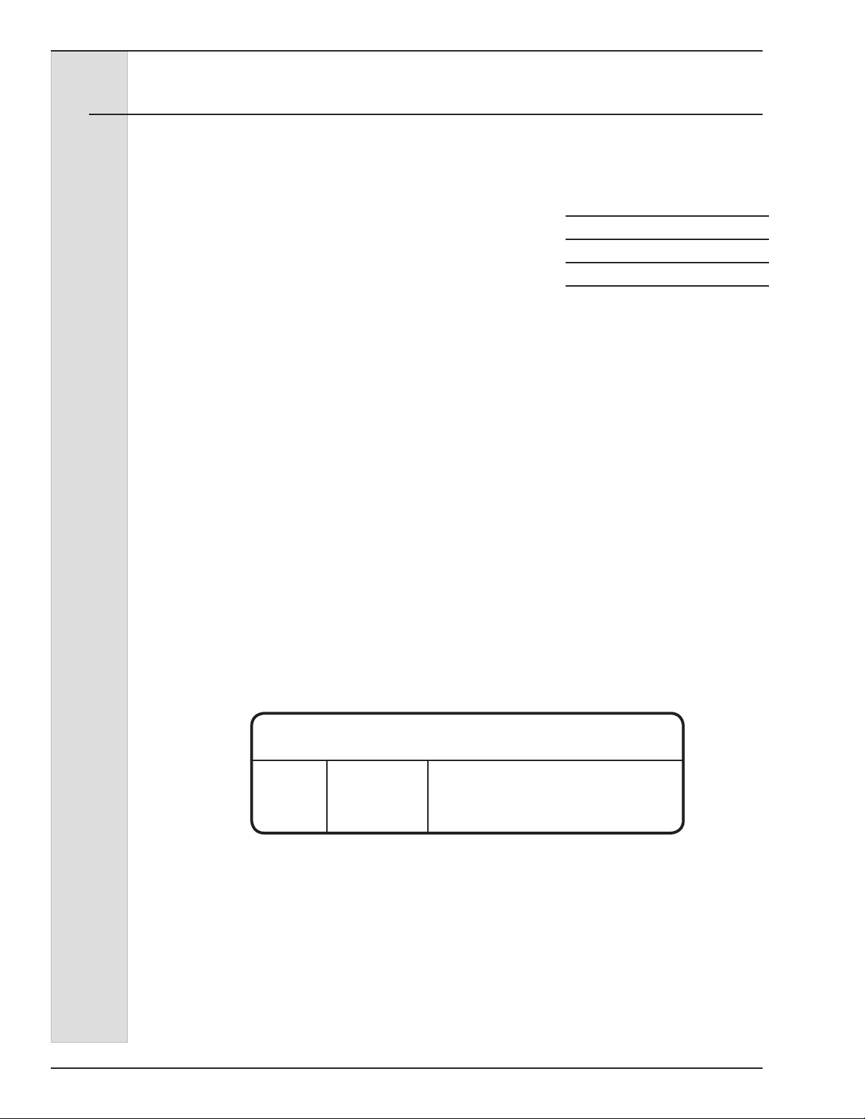
(The decals on the next page are
numbered 1 and 2. Those numbers
correspond to the numbers in the table
below. The table provides the part
number, description, and quantity for each
decal.)
No. Part No. Description (Qty)
1 HC165126 Decal — Panel Removal Warning (3)
2 HC165025 Decal — Beater Warning (1)
184592-01iv
ELECTRO FREEZE Shake Model CS705-M2
Safety Decal Locations
1 P/N HC165126
Hazardous moving parts.
Machine starts automatically.
Do not operate with panel
removed.
2 P/N HC165025
Hazardous rotating beater shaft. Do not
operate unit with dispense head removed.
Before removing dispense head:
1. Turn all control switched to “OFF”, and
2. Disconnect all power supplies. Unit
may have more than one power supply.
184592-01 v

ELECTRO FREEZE Shake Model CS705-M2
Table of Contents
SECTION DESCRIPTION PAGE
SAFETY ...........................................................................................ii
PART I
1. INTRODUCTION .............................................................................1
2. NOTE TO INSTALLER ...................................................................1
3. ELECTRICAL REQUIREMENTS ................................ 2
4. SPECIFICATIONS ...........................................................................2
4.1 Particulars. ......................................................................................2
4.2 Data Plate ........................................................................................3
4.3 Reference Information .....................................................................3
4.4 Installation Date ..............................................................................3
4.5 Dimensions. ..................................................................................... 4
5. PART NAMES AND FUNCTIONS .............................................5
6. OPERATOR CONTROLS & INDICATORS ................... 7
6.1 Selector Switch ...............................................................................7
6.2 Day-Night Switch .............................................................................7
6.3 “ADD MIX” Indicator Light ................................................................7
6.4 Mix Float ..........................................................................................8
6.5 Mix Feed Tube & Regulator ..............................................................8
7. DISASSEMBLY AND CLEANING .............................................9
7.1 Accessories ....................................................................................9
7.2 Disassembly Instructions ...............................................................10
7.3 Cleaning Instructions ....................................................................11
8. ASSEMBLY .......................................................................................13
9. START-UP INSTRUCTIONS .....................................................15
9.1 Sanitizing ......................................................................................15
9.2 Priming ...........................................................16
vi
184592-01vi

ELECTRO FREEZE Shake Model CS705-M2
Table of Contents - continued
SECTION DESCRIPTION PAGE
10. CLOSING PROCEDURES .............................................. 18
10.1 Night Switch Operation ................................................................. 18
10.2 Draining Product From Freezer ..................................................... 19
11. SOFT SERVE INFORMATION ........................... 20
11.1 Overrun ........................................................................................ 20
11.2 Rerun ............................................................................................20
12. ROUTINE MAINTENANCE ............................................ 21
13. TROUBLESHOOTING TABLE .......................... 24
PART II
MODEL CS705-M2 REPLACEMENT PARTS WITH ILLUSTRATIONS
*
* Refer to Part II Table of Contents for help with locating part numbers and illustrations.
vii
184592-01 vii


1 Introduction
ELECTRO FREEZE Shake Model CS705-M2
The CS705-M2 Freezer is designed to
produce soft serve ice cream, ice milk,
yogurt, and similar frozen dairy products,
with a product serving temperature
range of 15° to 25ºF (-9° to -4°C). If such
products are prepared from powdered
concentrate, they should be precooled
to 40ºF (4°C) prior to introduction to
the freezer. Use of other products in
this machine is considered misuse (see
Warranty).
This manual has been prepared to assist
you in the proper operation and general
maintenance of the Electro Freeze Model
CS705-M2 freezer.
Make sure all personnel responsible for
equipment operation completely read and
understand this manual before operating
the freezer. When properly operated and
maintained the freezer will produce a
consistent quality product.
If you require technical assistance, please
contact your local authorized Electro
Freeze Distributor, as follows:
Name: ________________________
Address: ______________________
Phone: ________________________
For factory service
assistance — contact H.C. Duke & Son,
LLC, Electro Freeze Service Department
as follows.
Phone: 309-755-4553
800-755-4545
FAX: 309-755-9858
E-mail: service@hcduke.com
2 Note to Installer
This freezer must be installed and
serviced by an Electro Freeze Distributor
or authorized service technician
in accordance with the installation
instructions in this manual.
Verify the weight of the freezer. Ensure
a counter or table of sufcient strength
is used to hold this weight and prevent
excessive vibration.
Air cooled models require a minimum of
3-inches (7.6 cm) air space on both sides
and back of the freezer for adequate
ventilation.
If this freezer is to be used in a selfservice application, it is recommended
that the machine be tted with a self-
service kit. Contact your Electro Freeze
Distributor or H. C. Duke & Son, LLC for
this kit.
Test the operation of the head safety
switch prior to placing the freezer
in service. See Section 12, Routine
Maintenance, Monthly.
After installation the warranty registration
card must be completed and returned to
validate the warranty.
184592-01 1
ELECTRO FREEZE Shake Model CS705-M2
2.1 Uncrating and Inspection
CAUTION
Be sure to properly support
the machine when removing
bolts and installing legs or
casters.
When the unit is received and while
the carrier is still present, inspect the
shipping carton for any damage that
may have occurred in transit. If the
SHOCKWATCH® label indicates red and/
or the carton is broken, torn, or punctured
note the damage on the carrier’s freight
bill and notify the carrier’s local agent
immediately. Also note on the freight bill.
2.2 Installation
CAUTION
All materials and connections
must conform to local
requirements and be in
compliance with the National
Electrical Code (NEC).
CAUTION
Tip Hazard. Front side of
freezer must remain positioned
on door side of cart. DO NOT
reverse position of freezer on
cart.
1. Remove the carton from the pallet,
and move the machine as close as
possible to the permanent location.
2. Remove the shipping bolts on the
bottom of the freezer and remove the
freezer from the pallet.
CAUTION
Use caution when moving the
freezer to avoid a tip hazard.
3. A minimum 3-inch (7.6 cm) air space
is required on both sides and back of
the freezer for adequate ventilation.
4. Test the operation of the head and
ex shaft cover safety switches prior
to placing the freezer in service. See
Section 12, Routine Maintenance,
Monthly.
1. This freezer is designed for indoor use
and must be protected from outdoor
weather conditions.
2. This freezer requires a potable water
connection for the rinse line. The
water inlet is located at the back of
the freezer next to the power supply. A
3/8” MPT water inlet connector will be
needed.
184592-012
ELECTRO FREEZE Shake Model CS705-M2
2.3 Electrical Requirements
CAUTION
All materials and connections
must conform to local
requirements and be in
compliance with the National
Electric Code (NEC).
CAUTION
To prevent accidental electrical
shock, a receptacle with
a positive earth ground is
required.
1. Always verify electrical specications
on the data plate (gure 4-1) of
each individual freezer. Data plate
specications will always supersede
the information in this manual.
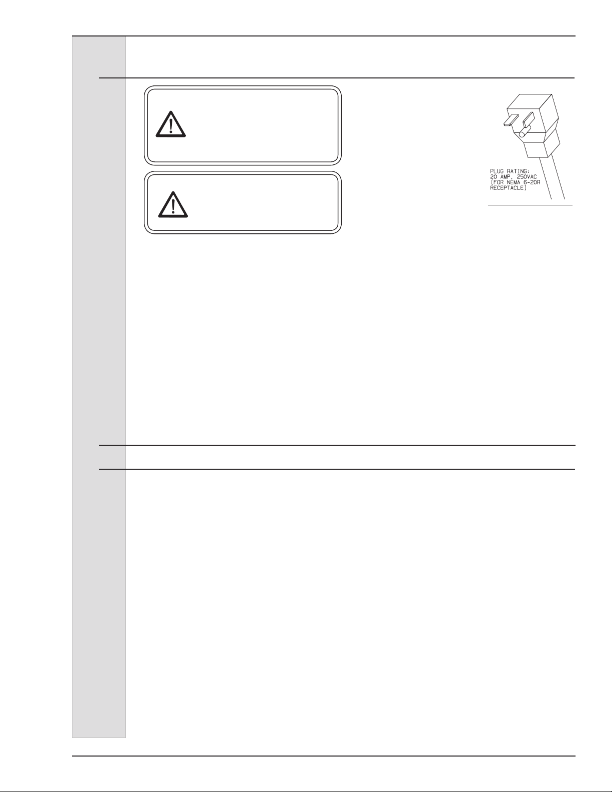
2. This freezer requires a protected 20
amp 230 volt circuit. Connect the
freezer to a circuit separate from any
other electrical equipment. The power
cord on this freezer connects to a
NEMA 6-20R receptacle. See Figure
3-1.
3. Supply voltage
must be within
±10% of voltage
indicated on
the nameplate.
Request your
local power
company
to correct
Figure 2-1
any voltage
problem.
4. The control transformer in the
electrical box is factory wired to 208
volts (red) wire tap for 208V nominal
power supply. If power supply is
between 230-240 volts use 240V
(orange) wire tap on transformer.
5. Beater Shaft Rotation - Freezers are
designed for clockwise rotation when
viewed from front of freezer. 1ph
machines are pre-wired for proper
rotation. On 3phase machines,
phase wires to freezer should be
connected to produce proper beater
rotation. This is to be done by a
freezer technician.
3 Specifications
3.1 Particulars
Width (in/cm) 18.4/46.7
Height (in/cm) 58.9/149.7
Depth (in/cm) 28.1/71.4
Weight (lbs/kg) 250/113.4
Voltage* 208-230/60/1
Min. Circuit Ampacity 20.0
Compressor 1 HP/8000 (BTUH)
.75 kw (Motor)
2.3 kw (Cooling)
Beater Motor 1/2 HP/.37 kw
Refrigerant R-404a
Charge 32.0 oz/.91 kg
Cooling Air
Hopper 20 qts/18.8 liters
Cylinder 7 qts/7.1 liters
*Contact factory for other voltages.
Noise: The Steady acoustic pressure level, for both air cooled and
water cooled freezers, is less than 70dB(A).
184592-01 3
ELECTRO FREEZE Shake Model CS705-M2
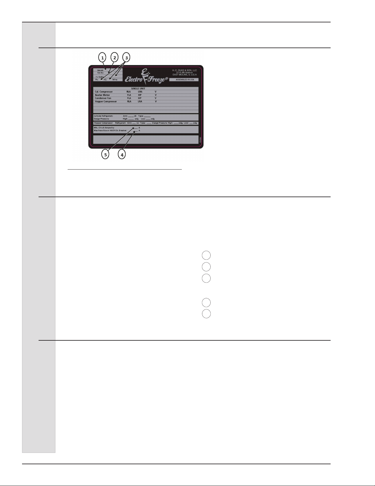
3.2 Data Plate
Figure 4-1
3.3 Reference Information
The data plate provides important
information that the operator should
record and have available for parts
ordering, warranty inquiries and service
requests.
Write in Reference
Information HERE!
3.4 Installation Date
Fill in the date of installation, and the name, address, and phone number of the
installer in the space provided below. This information will be needed when ordering
parts or service for the CS705-M2 Freezer.
Date of installation: _____________________________________
Installed by: _____________________________________
Address: _____________________________________
_____________________________________
Phone: _____________________________________
Fill in the following information as soon as
you receive the Electro Freeze CS705-M2.
(The item numbers — encircled, below —
correspond with the call-out numbers in
gure 4-1.)
1 Model Number: ________________
2 Serial Number: _________________
3 Electrical Spec: Voltage _______
Phase _______ Hertz ___________
4 Maximum Fuse Size: __________
5 Minimum Circuit Ampacity: ______
184592-014
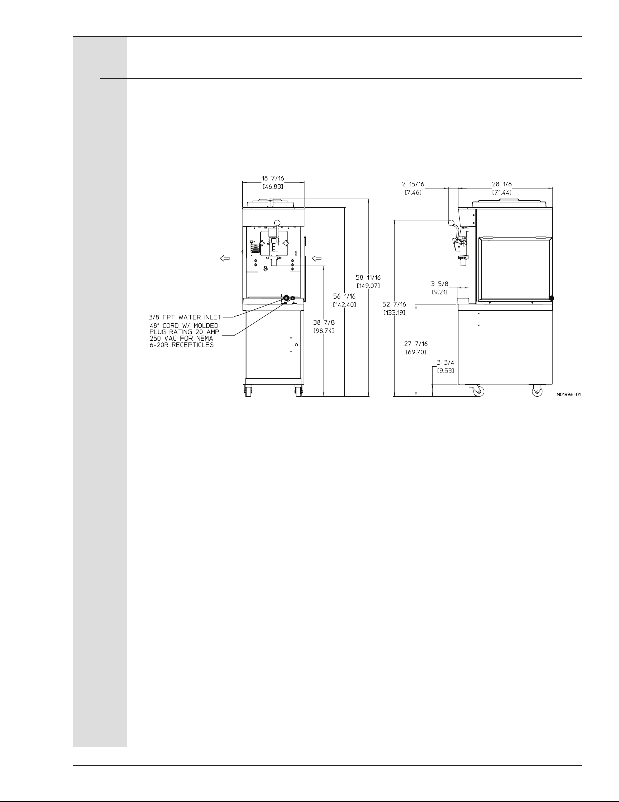
3.5 Dimensions
The dimensions of the CS705-M2
Freezer are provided in gure 4-2, below.
ELECTRO FREEZE Shake Model CS705-M2
AIR OUT
AIR IN
Figure 4-2 Electro Freeze Model CS705-M2 Dimensions
184592-01 5
ELECTRO FREEZE Shake Model CS705-M2
4 Part Names and Functions
184592-016

ELECTRO FREEZE Shake Model CS705-M2
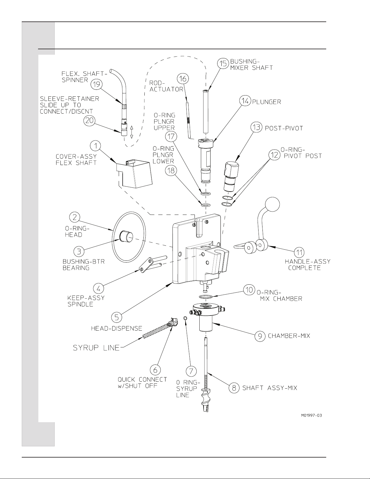
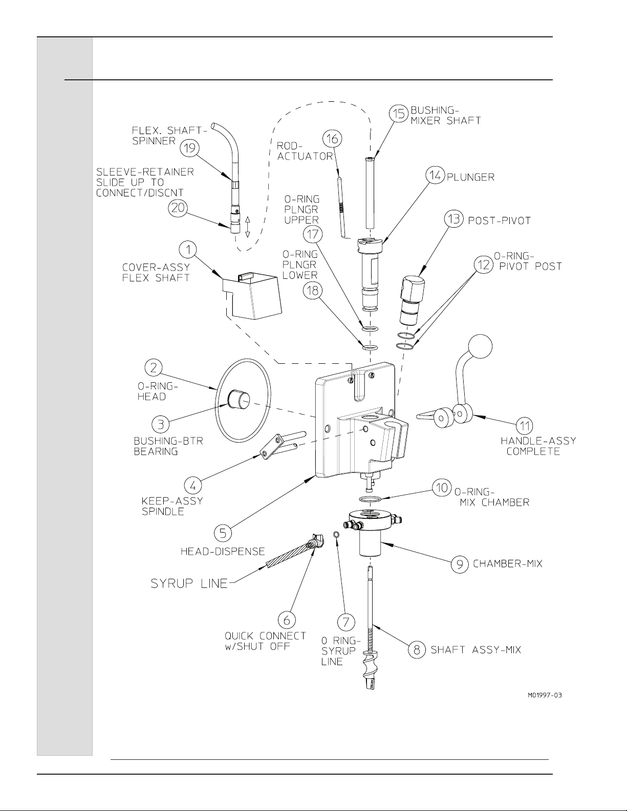
4 Part Names and Functions
The following part names and descriptions refer to gure 4-1.
1.) COVER - ASSY FLEX SHAFT:
Protects from accidental contact with
rotating shaft. Must be in place to
operate.
2.) O-RING - HEAD:
Seals the head to the freezing cylinder.
Must be lubricated.
3.) BUSHING - BEATER BEARING:
Holds the beater in place at the front
of the cylinder. Must be inserted
into the head and lubricated
before assembly.
4.) KEEPER - ASSY SPINDLE:
Secures the handle to the head.
5.) HEAD - DISPENSE:
Encloses the freezing cylinder and
provides an opening for product to
be dispensed.
6.) QUICK CONNECT WITH SHUT
OFF:
Allows syrup line to be removed from
the mix chamber.
7.) O-RING - SYRUP LINE:
Prevents syrup from leaking.
14.) PLUNGER - DISPENSING:
Seals the product opening in the head
when closed. Allows product to ow
when open.
15.) BUSHING - MIXER SHAFT:
Holds the mixing shaft in place.
Prevents wear on plunger.
16.) ROD - ACTUATOR:
Starts the freezer when dispensing.
Must be in place before product can
be dispensed.
17.) O-RING - PLUNGER-UPPER
18.) O-RING - PLUNGER-LOWER:
Seals the plunger in the head.
Must be lubricated to seal and slide
properly.
19.) SHAFT - FLEXIBLE W/CASING
16-1/2:
Spins the mix shaft.
20.) CONNECT - ASSY DRIVE:
Quick connector used to connect or
disconnect the exible shaft from the
mix shaft.
8.) SHAFT - ASSY MIX:
Mixes avor into shake mix.
9.) CHAMBER - MIX:
Delivers syrup to the shake mix.
10.) O-RING - CHAMBER:
Prevents mix from leaking. Lightly
lubricate.
11.) HANDLE - ASSY COMPLETE:
Opens and closes the plunger to start
and stop the ow of product from the
freezer.
12.) O-RING - PIVOT POST:
Holds the pivot post in place. Lightly
lubricate.
13.) POST - PIVOT:
Holds the handle in place.
184592-01 7

ELECTRO FREEZE Shake Model CS705-M2
4 Part Names and Functions
Figure 4-2 Beater Shaft Assembly
The following part names and descriptions
refer to gure 4-2.
1.) SHAFT-BEATER:
Rotates in the freezing cylinder,
blending air and mix and ejecting
product.
2.) BLADE-SCRAPER:
Scrapes the frozen product from
the freezing cylinder wall.
3.) SEAL (CUP) - BEATER SHAFT:
Seals the opening between the
freezing cylinder and the beater.
DO NOT LUBRICATE.
4.) WASHER - SHAFT SEAL:
Holds the shaft seals together.
Must be lubricated.
184592-018

ELECTRO FREEZE Shake Model CS705-M2
O-Ring
Insert-Assy. Mix
Feed
4 Part Names and Functions - continued
O-RING
TUBE-MIX FEED
INSERT - ASSY.
MIX FEED
O-RING
Figure 4-3 Mix Feed Tube
The following part names and descriptions refer to gure 4-3.
1.) TUBE-MIX FEED:
Meters the correct amount of mix
and air into the freezing cylinder from
the hopper.
2.) INSERT-ASSEMBLY MIX FEED
(Regulator):
Regulates mix ow. Open position for
day operation and closed position for
night.
3.) O-RING-INSERT ASSEMBLY:
Holds the insert in place in the mix
tube. Must be lubricated.
4.) O-RING-MIX FEED ASSEMBLY:
Seals the opening between the hopper
and mix feed tube. O-rings do not need
lubrication.
184592-01 9
ELECTRO FREEZE Shake Model CS705-M2
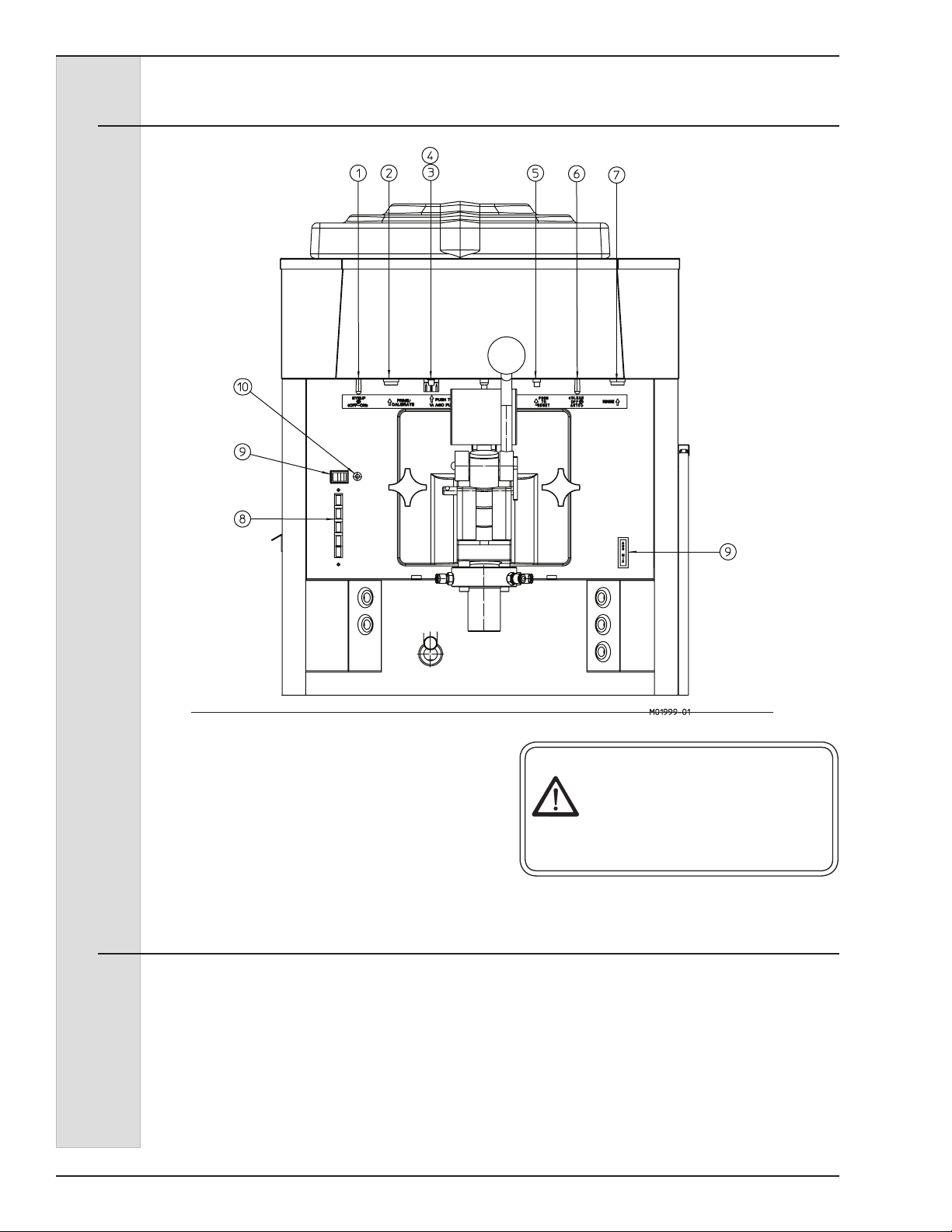
5 Operator Controls
Figure 5-1
The following paragraphs describe
the operator controls and indicators.
Refer to gure 5-1 for location of these
controls and indicators on the freezer.
NOTE: The head, actuator rod, and metal
cover must be in place before the beater
will operate.
5.1 Syrup Pump Switch (1)
This two-position switch controls the
operating mode of your freezer.
a. “ON” (right) — This position
operates the syrup motor. Always use
this mode when operating the syrup
system.
b. “OFF” (left) — In this position the
syrup motors do not run.
—continued
CAUTION
Test operation of the head switch
prior to placing the freezer in
service. See Section 12, Routine
Maintenance, Monthly.
184592-0110

ELECTRO FREEZE Shake Model CS705-M2
5 Operator Controls — continued
5.2 Prime / Calibrate (2)
This push button switch is used for
priming and calibrating the avor syrups.
With the syrup switch in the “ON” position,
the selector switch (5) in “AUTO” and
a avor selection (8) made, pressing
this button will activate the pump for
that avor to ush and prime the avor
delivery line and to allow calibration of the
syrup ow.
5.3 Reset - Circuit Breaker Spinner Motor (3)
This control protects the spinner motor
against failure from an overload condition
by automatically shutting it down. To
restart wait 2-3 minutes, then depress the
reset button.
If the circuit breaker trips frequently,
your spinner mechanism and circuitry
should be checked. Contact your
Electro Freeze Distributor.
5.4 Syrup Pump Fuse (4)
This holds the AGC fuse for the syrup &
malt pumps.
5.5 Reset — Circuit Breaker Beater Motor (5)
This control protects the beater motor
against failure from an overload condition
by automatically shutting down the
freezer. To restart properly, turn the
SELECTOR switch (5) to “OFF”, wait 2-3
minutes, then depress the reset button
and turn the SELECTOR switch back to
the “AUTO” or “CLEAN” position.
Important:
If the circuit breaker trips frequently,
your freezer should be checked for
proper product temperature, overrun
and voltage. Contact your Electro
Freeze Distributor.
Important:
5.6 Selector Switch (6)
This three-position switch controls the
operating mode of your freezer.
a. “CLEAN” (left) — This position
operates the beater only (no
refrigeration). Always use this mode
when performing cleaning and
sanitizing operations.
b. “OFF” (center) — In this position
the beater motor and refrigeration
system will not operate.
184592-01 11
Important:
Do not use the “FREEZE” position with
water or sanitizer in the cylinder — the
freezer will be damaged.
c. “AUTO” (right) — This position
activates both the beater motor and
refrigeration unit. This is the normal
operating position which will maintain
a cylinder temperature of 26° to 28°F
(-3° to -2°C).

ELECTRO FREEZE Shake Model CS705-M2
5 Operator Controls — continued
5.7 Rinse Switch (7)
This momentary switch activates the rinse
water solenoid valve and the spinner
motor to rinse the mixing chamber
between avor changes to eliminate avor
carryover.
5.8 Flavor Selection Buttons (8)
T
hese push buttons are used to select the
avor of shake to be dispensed. Press
the button for the desired avor. Selection
of another button will cancel the previous
selection. ‘Vanilla’ provides product
from the cylinder only, with no added
avoring. When ‘Chocolate’, Strawberry’,
‘Banana’ , or ‘Special’ are selected, that
corresponding pump will operate when
product is dispensed.
5.9 Malt Switch (9)
When the malt switch is turned on the
malt pump will operate when the handle is
pulled.
5.10 Malt Light (10)
This light indicates when the Malt switch
is turned on.
5.11 Indicator Light - “ADD MIX” (11)
This light indicates the mix in the mix
hopper is at a low level and should be
relled as soon as possible. Always
maintain at least 2 inches (5.1 cm) of mix
in the hopper. For best operating results
keep hopper full.
5.12 Mix Float (not shown)
When this oat is mounted on the oat
stem inside the hopper it automatically
senses the mix level. It activates the “Add
Mix” light.
184592-0112

ELECTRO FREEZE Shake Model CS705-M2
6 Disassembly and Cleaning
CAUTION
To avoid electrical shock or
contact with moving parts,
make sure all switches are in
the “OFF” position and that
the main power supply is
disconnected.
It is important that the freezer be
disassembled, washed, lubricated and
sanitized before operation.
6.1 Cleaning Accessories
The following accessories shipped with the freezer are necessary for cleaning, sanitizing,
and disassembly/assembly:
1. BRUSH - HC158010. 6-inch diameter
used to clean the cylinder.
2. HANDLE - HC158012. 36-inch handle
used with brush p/n HC15010.
3. BRUSH - HC158077. 9/16-inch in
diameter with 36-inch handle used to clean
drain tube.
4. BRUSH - DOUBLE END - HC158003.
1-1/8-inch diameter and 7/16-inch diameter
used for cleaning mix feed tube and general
cleaning.
5. TOOL - O-RING REMOVAL.
HC169374. Aids in removing O-rings from
plunger, head, air relief plug, and spindle.
6. LUBRICANT - COMPOUND 7
(SEVEN) HC158066. Approved lubricant for
moving parts, peristolic tubes and O-rings.
7. BRUSH - HC158026. 1-inch in
diameter 12 inches long used to clean the
hopper walls.
The cleaning and sanitizing instructions
explained in this manual are required to
maintain a clean, sanitary freezer. The
freezer should be disassembled, cleaned,
reassembled, lubricated and sanitized to
ensure the best possible product quality
and freezer operation.
Persons assembling, cleaning, or
sanitizing the freezer must wash and
sanitize hands and forearms with an
approved sanitizer.
8. WASH BOTTLE - HC196103. used to
ush the plunger and hopper walls.
9. BRUSH - HC158028. 3/8 inch
diameter x 1/2-inch 21 inch handle used to
clean mix chamber ports and syrup hoses.
9. BEAKER - 150 ML HC196109. Used
in syrup calibration. (not shown)
10. KIT - O-RING. Contains all O-rings
and seals needing replacement on a regular
basis. (not shown)
HC158066 LUBRICANT-COMPOUND 7 (SEVEN)
5.3 OZ TUBE
Figure 6-1 Accessories
184592-01 13
ELECTRO FREEZE Shake Model CS705-M2
6.2 Disassembly Instructions
Figure 6-2 Dispense Head Assembly
184592-0114
 Loading...