

ELECTRO FREEZE CS700-FG Operator's Manual
OPERATOR’S MANUAL
with Illustrated Parts List
COMPACT SERIES
SHAKE FREEZER
Model CS700-FG
185231 - 2/14
H. C. Duke & Son, LLC P/N 185231 - November 2015 Printed in U.S.A.


Operator’s Manual
for the
Electro Freeze Model CS700-FG
Compact Series
Shake Freezer
All contents © Copyright 2015 H.C. Duke & Son, LLC, 2116 Eighth Avenue, East Moline, Illinois 61244
i
ELECTRO FREEZE Shake Model CS700-FG
SAFETY FIRST!
Follow these four steps to safety ....
1. Recognize Safety Information ....Look for this
safety alert symbol throughout this manual.
When you see this symbol on your freezer or in
this manual, be alert to the potential for personal
injury. Follow recommended precautions and safe
operating practices.
2. Understand Signal Words ....
The signal words — DANGER, WARNING
DANGER
WARNING
CAUTION
and CAUTION — are used with the safety alert
symbol (DANGER decals on the freezer may or
may not have the safety alert symbol, but the
message is the same). Decals with the words
DANGER, WARNING or CAUTION appear on
the freezer. DANGER identies the most serious
hazard. Decals with the words DANGER or
WARNING are typically near specic hazards
on the freezer. General precautions are listed on
CAUTION safety decals.
In this manual, CAUTION messages with the
safety alert symbol call attention to safety
messages.
ii
ELECTRO FREEZE Shake Model CS700-FG
SAFETY FIRST!
3. Follow Safety Instructions ....
Read and understand all safety messages in
this manual. Read and understand the decal
safety messages on your freezer. Take notice
of the location of all decals on the freezer and
keep the safety decals in good condition. Check
them periodically and replace missing, damaged
or illegible safety decals. The safety decals
must remain in place and legible for the life of
the freezer. If you need new decals, use the
information and illustrations on pages iv and v
of this manual to identify the decal and order
replacement parts.
DO NOT attempt to operate the CS700 freezer
until you read and understand all safety messages
and the operating instructions in this manual.
4. Operate Safely ....
DO NOT allow untrained personnel to maintain
or service this machine. Failure to follow this
instruction may result in severe personal injury. DO
NOT operate the freezer unless all service panels
and access doors are secured with screws. DO
NOT attempt to maintain or repair the freezer until
the main power supply has been disconnected.
Contact your local Electro Freeze Distributor for
authorized service.
iii
ELECTRO FREEZE Shake Model CS700-FG
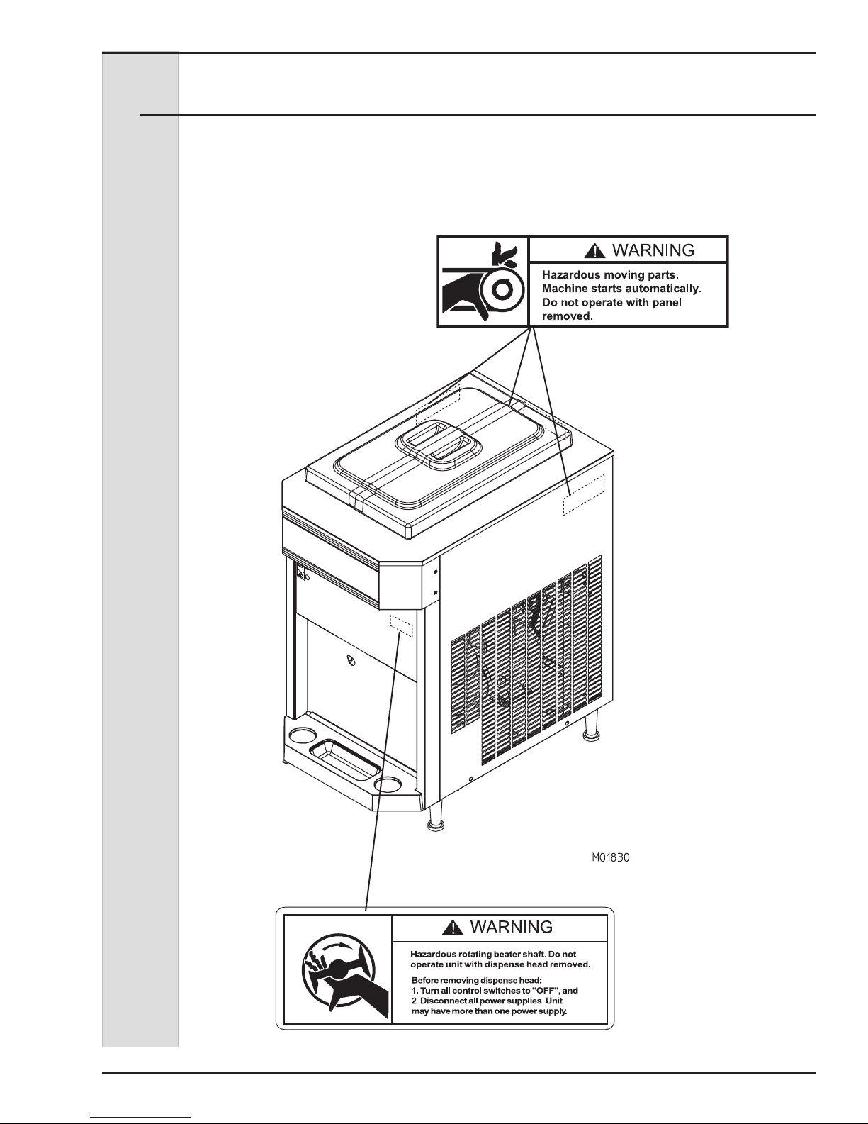
Safety Decal Locations
Do not attempt to operate the freezer
until all safety precautions and operating
instructions in this manual are read and
understood.
Take notice of all warning, caution,
instruction and information decals (or
labels) on the freezer as shown in the
gure on the following page. The labels
have been put there to help maintain a
safe working environment.
The labels have been designed to
withstand washing and cleaning. All
labels must remain legible for the life of
the freezer. Check labels periodically
to be sure they can be recognized as
warning labels.
If it is necessary to replace any label,
please contact your local authorized
Electro Freeze Distributor or H. C. Duke &
Son. When ready to order you will need to
determine the (1) part number, (2) type of
label, (3) location of label, and (4) quantity
required, and include a return shipping
address.
You may contact your local authorized
Electro Freeze Distributor, as follows:
Name:
Address:
Phone:
or — for factory service assistance —
contact H. C. Duke & Son, LLC. Electro
Freeze Service Department by phone or
FAX:
Phone: 309-755-4553
800-755-4545
FAX: 309-755-9858
E-mail: service@electrofreeze.com
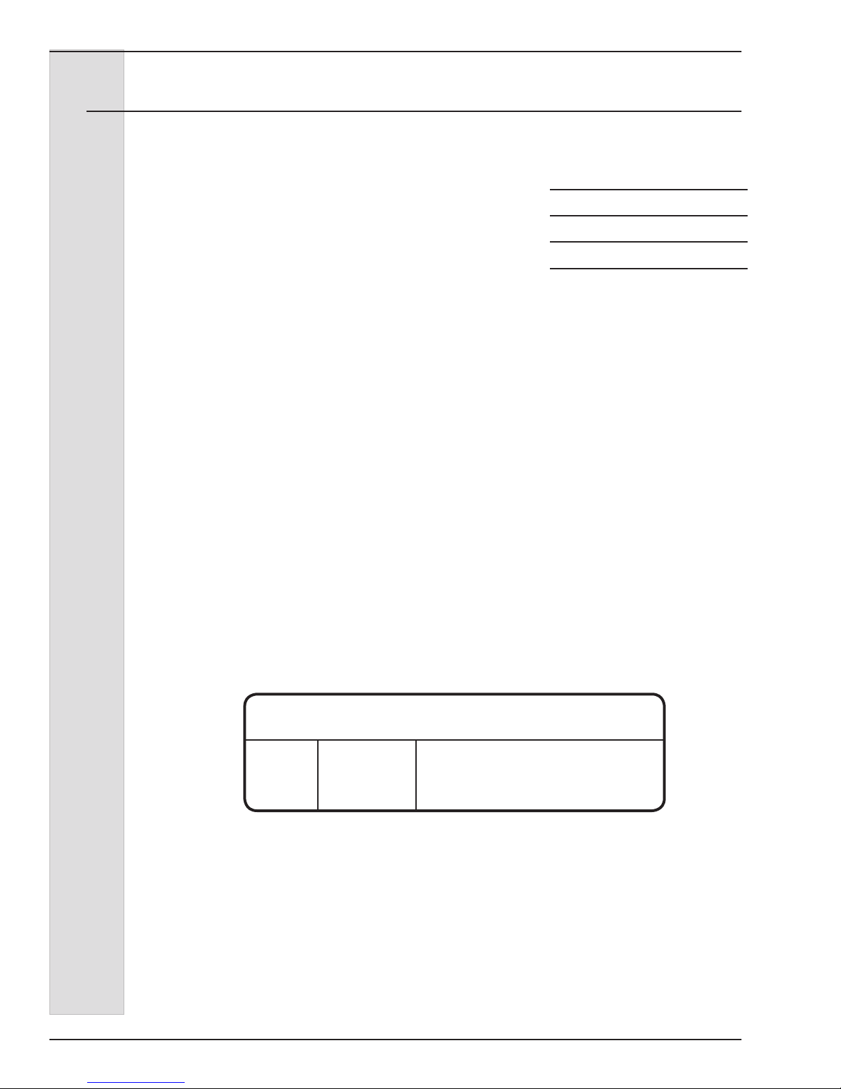
(The decals on the next page are
numbered 1 and 2. Those numbers
correspond to the numbers in the table
below. The table provides the part
number, description, and quantity for each
decal.)
No. Part No. Description (Qty)
1 HC165126 Decal — Panel Removal Warning (3)
2 HC165025 Decal — Beater Warning (1)
iv
ELECTRO FREEZE Shake Model CS700-FG
Safety Decal Locations
1 P/N HC165126
2 P/N HC165025
v

ELECTRO FREEZE Shake Model CS700-FG
Table of Contents
SECTION DESCRIPTION PAGE
SAFETY ...........................................................................................ii
SAFETY DECALS LOCATIONS ............................................ iv
PART I
1. INTRODUCTION .............................................................................1
2. NOTE TO INSTALLER ...................................................................1
2.1. Electrical Requirements .................................................................2
3. SPECIFICATIONS ...........................................................................2
3.1 Particulars. ......................................................................................2
3.2 ...................................................................................Data Plate
3
3.3 Reference Information .....................................................................3
3.4 Installation Date ..............................................................................4
3.5 Dimensions. .....................................................................................5
4. PART NAMES AND FUNCTIONS .............................................6
5. OPERATOR CONTROLS & INDICATORS .................. 10
5.1 Selector Switch .............................................................................11
5.2 Reset -Circuit Breaker ...................................................................11
5.3 Indicator Light “ADD MIX” .............................................................11
5.4 Indicator Light “MIX OUT” ..............................................................11
5.5 Mix Float ........................................................................................11
6. DISASSEMBLY AND CLEANING ...........................................12
6.1 Accessories ..................................................................................12
6.2 Disassembly Instructions ...............................................................13
6.3 Cleaning Instructions ....................................................................15
7. ASSEMBLY .......................................................................................17
8. START-UP INSTRUCTIONS .....................................................20
8.1 Sanitizing ......................................................................................20
8.2 Priming .........................................................................................21
vi

ELECTRO FREEZE Shake Model CS700-FG
Table of Contents - continued
SECTION DESCRIPTION PAGE
9. CLOSING PROCEDURES ........................................................ 22
9.1 End of Day Operation ....................................................................... 22
9.2 Draining Product From Freezer ........................................................ 23
10. PRODUCT INFORMATION ............................... 24
10.1 Overrun ........................................................................................ 24
10.2 Rerun ............................................................................................24
11. SPINDLE MIXER (OPTIONAL) .......................... 25
11.1 Preparation .................................................................................. 25
11.2 Cleaning and Sanitizing - Spindle Mixer ........................................ 25
11.2.1 Daily Cleaning ...................................................................25
11.2.2 Daily Sanitizing ..................................................................26
11.3 Operation-Spindle Motor ...............................................................26
12. ROUTINE MAINTENANCE ............................................ 27
13. TROUBLESHOOTING TABLE .......................... 31
PART II
MODEL CS700 REPLACEMENT PARTS WITH ILLUSTRATIONS *
* Refer to Part II Table of Contents for help with locating part numbers and illustrations.
vii


ELECTRO FREEZE Shake Model CS700-FG
1 Introduction
This freezer is designed to produce
milkshakes with a temperature range of
24° to 30°F (-4° to -1°C). If such products
are prepared from powdered concentrate,
they should be precooled to 38°F (3°C)
prior to introduction to the freezer. Use
of other products in this machine is
considered misuse (see Warranty).
This manual has been prepared to assist
you in the proper operation and general
maintenance of the H.C. Duke & Son,
LLC. Model CS700 Freezer.
Your freezer will not compensate for or
correct any assembly or priming errors
made during the initial start-up. Therefore,
it is important to follow the assembly
and priming procedures detailed in this
manual.
Make sure all personnel responsible for
equipment operation completely read and
understand this manual before operating
the freezer. When properly operated and
maintained, the freezer will produce a
consistent quality product.
If you require technical assistance, please
contact the factory service department at
H.C. Duke & Son, LLC. as follows:
Name _________________________
Address________________________
_______________________________
Phone__________________________
Phone: (309) 755-4553
(800) 755-4545
Fax: (309) 755-9858
E-mail: service@hcduke.com
2 Note to Installer
This freezer must be installed and
serviced by an Electro Freeze Distributor
or authorized service technician
in accordance with the installation
instructions in this manual.
Verify the weight of the freezer. Ensure
a counter or table of sufcient strength
is used to hold this weight and prevent
excessive vibration.
Air cooled models require a minimum of
3-inches (7.6 cm) air space on both sides
and back of the freezer for adequate
ventilation.
Freezer is equipped with a deector plate
that will need to be mounted. Facing
the front of the freezer the plate will
be mounted on the screws on the left
side panel. The deector is required to
prevent air from recirculating back to the
freezer. Failure to install deector will void
warranty.
If this freezer is to be used in a selfservice application, it is recommended
that the machine be tted with a self-
service kit. Contact your Electro Freeze
Distributor or H. C. Duke & Son, LLC. for
this kit.
Test the operation of the head switch
prior to placing the freezer in service.
See Section 11, Routine Maintenance,
Monthly.
After installation the warranty registration
card must be completed and returned to
validate the warranty.
185231-17
1

ELECTRO FREEZE Shake Model CS700-FG
2.1 Electrical Requirements
CAUTION
All materials and
connections must conform
to local requirements and
be in compliance with the
National Electric Code (NEC).
CAUTION
To prevent accidental
electrical shock, a receptacle
with a positive earth ground
is required.
1. Always verify electrical
specications on the data plate (gure
3-2) of each individual freezer. Data plate
specications will always supersede the
information in this manual.
2. This freezer requires a protected
20 amp 230 volt circuit. Connect the
freezer to a circuit separate from any
other electrical equipment. The power
cord on this freezer connects to a NEMA
6-20R receptacle. See Figure 2-1.
3. Supply voltage must be within
±10% of voltage indicated on the
nameplate. Request your local power
company to correct any voltage problem.
4. The transformer in the electrical
box is factory wired for 240 volts. This
connection maybe used for all voltages
above 200 volts. If the power supply
is less than 200 volts, move the L2
transformer wire connector to the 208 volt
connector.
Figure 2-1
3 Specifications
3.1 Particulars
Width (in/cm) 18.4/46.7
Height (in/cm) 35.2/89.4
Depth (in/cm) 28.1/71.4
Weight (lbs/kg) 220/99.8
Voltage* 208-230/60/1
Min.Circuit Ampacity 20.0
Compressor 1 HP/8000 (BTUH)
.75 kw (Motor)
2.3 kw (Cooling)
Beater Motor 1/2 HP/.37 kw
Refrigerant R-404a
2
Charge 32.0 oz/.91 kg
Cooling Air
Hopper 20 qts/18.8 liters
Cylinder 7 qts/7.1 liters
*Contact factory for other voltages.
185231-17
ELECTRO FREEZE Shake Model CS700-FG
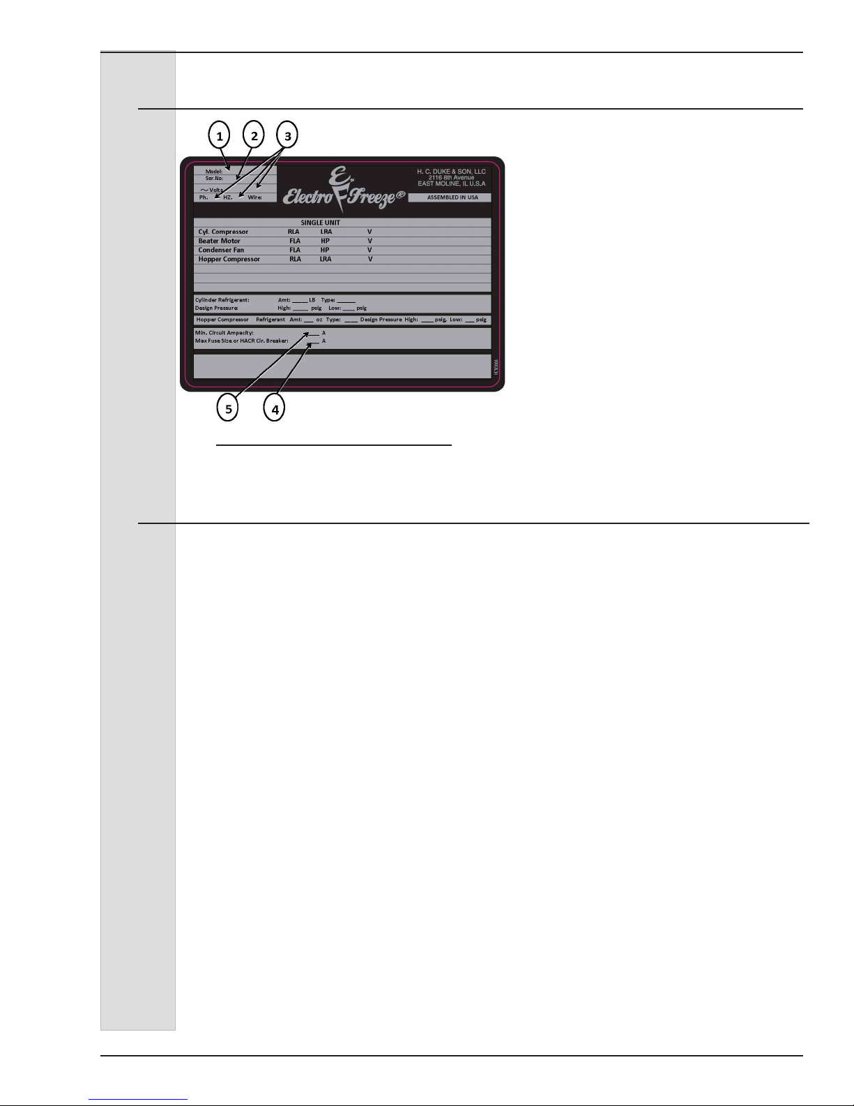
3.2 Data Plate
Figure 3-1
The data plate provides important
information that the operator should
record and have available for parts
ordering, warranty inquiries and service
requests.
3.3 Reference Information
Write in Reference
Information HERE!
Fill in the following information as soon as
you receive the Electro Freeze CS700-FG.
(The item numbers — encircled, below —
correspond with the callout numbers in
gure 4-1.)
1.) Model Number: _________________
2.) Serial Number:__________________
3.) Electrical Spec: Voltage ________
4.) Phase _______ Hertz _________
5.) Maximum Fuse Size: ____________
6.) Minimum Circuit Ampacity: _______
185231-17
3

ELECTRO FREEZE Shake Model CS700-FG
3.4 Installation Date
Fill in the date of installation, and the name, address, and phone number of the
installer in the space provided below. This information will be needed when ordering
parts or service for the CS700-FG Freezer.
Date of installation: _____________________________________
Installed by: _____________________________________
Address: _____________________________________
_____________________________________
Phone: _____________________________________
4
185231-17
ELECTRO FREEZE Shake Model CS700-FG
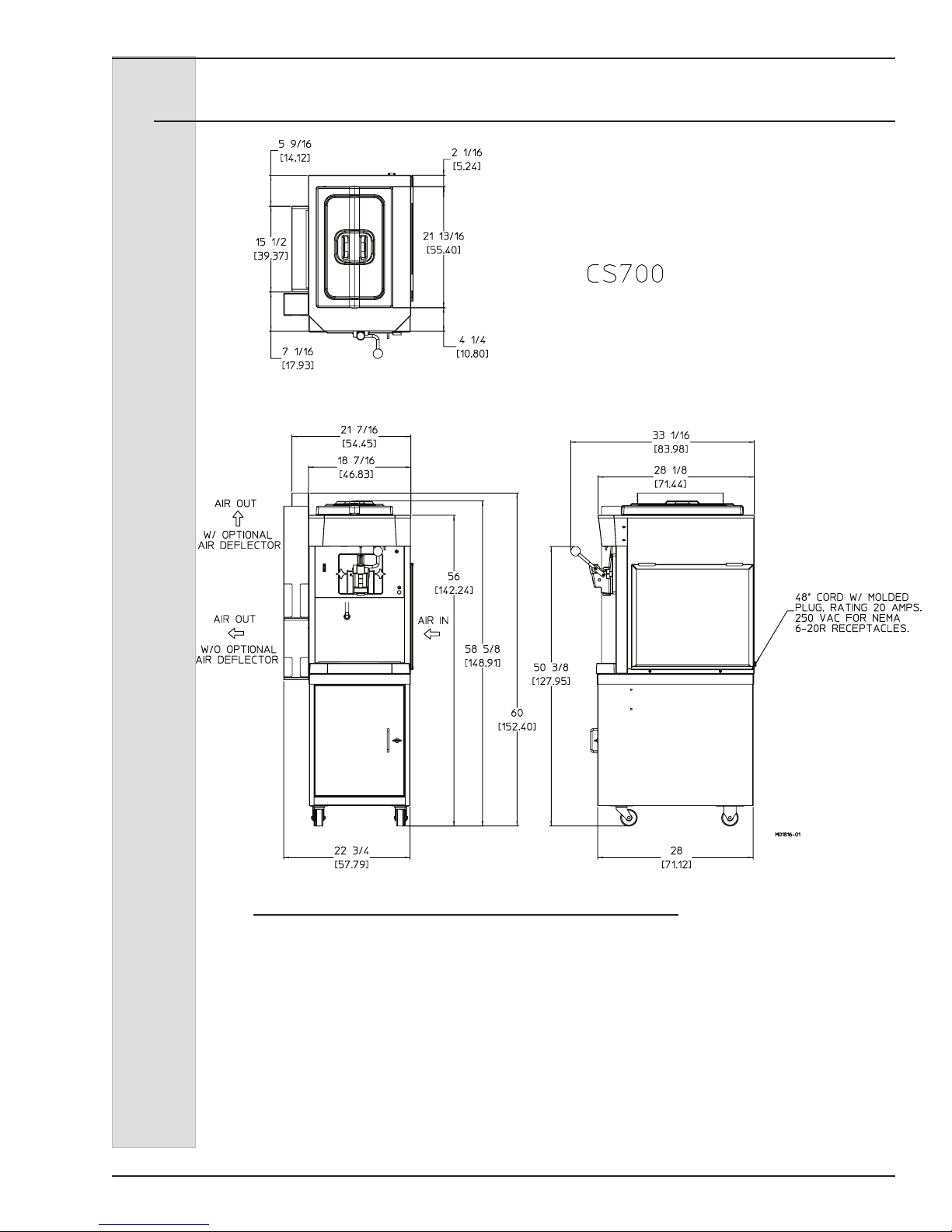
3.5 Dimensions
Figure 3-2 Electro Freeze Model CS700 Dimensions
185231-17
5
ELECTRO FREEZE Shake Model CS700-FG
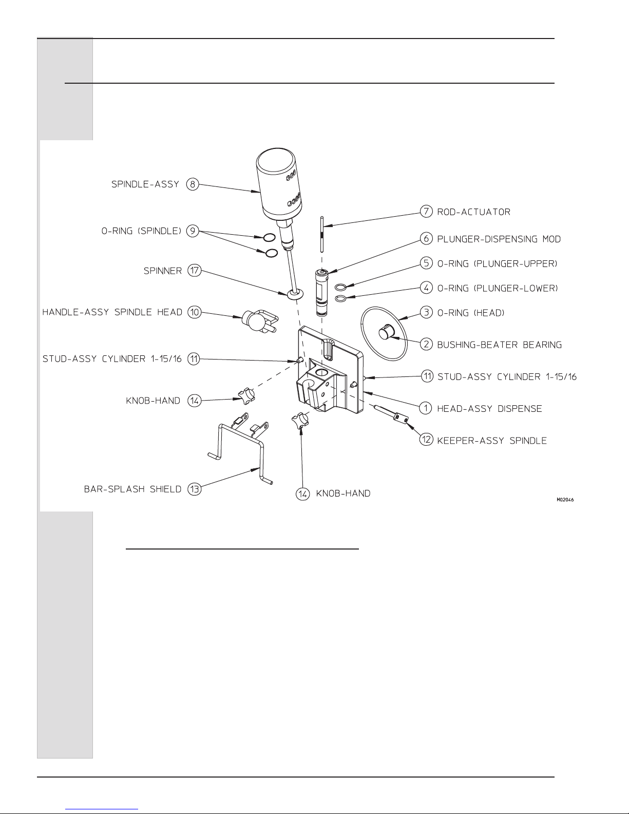
4 Part Names and Functions
Figure 4-1 Head Assembly
6
185231-17

ELECTRO FREEZE Shake Model CS700-FG
4 Part Names and Functions — continued
The following part names and descriptions refer to gure 4-1.
1.) HEAD - ASSY. DISPENSE: Encloses
the freezing cylinder and provides an
opening for product to be dispensed.
2.) BUSHING - BEATER BEARING:
Holds the beater in place at the front of
the cylinder. Must be inserted into the
head and lubricated before assembly.
3.) O-RING - HEAD: Seals the head
to the freezing cylinder. Must be
lubricated.
4.) O-RING - PLUNGER LOWER: Seals
the plunger in the head. Must be
lubricated to seal and slide properly.
5.) O-RING - PLUNGER UPPER: Seals
the plunger in the head. Must be
lubricated to seal and slide properly.
6.) PLUNGER: Seals the product opening
in the head when closed. Allows product
to ow when open.
7.) ROD - ACTUATOR: Starts the freezer
when dispensing. Must be in place
before freezer will operate.
8.) SPINDLE - ASSY.: Mixes the shake
as it is dispensed.
9.) O-RING - SPINDLE: Holds the spindle
or pivot post in place.
10.) HANDLE - DISPENSE: Opens and
closes the plunger to start and stop the
ow of product from the freezer.
11.) STUD - ASSY.: Hand knobs screw on
studs to hold head assembly in place.
12.) KEEPER: Secures the handle to the
head.
13.) BAR-SLASH SHIELD:
splash shield to the dispense head.
14.) KNOB - HAND: Secures the head to
the freezing cylinder.
185231-17
Attaches the
7
ELECTRO FREEZE Shake Model CS700-FG
T
4. Part Names and Functions — continued
4
WASHER - BEATER SHAFT
3
SEAL CUP- BEATER SHAFT
BEATER - ASSY.
1
SHAKE SHORT
2
BLADE - SHAKE SCRAPER
SEAL CUP- BEATER SHAF
3
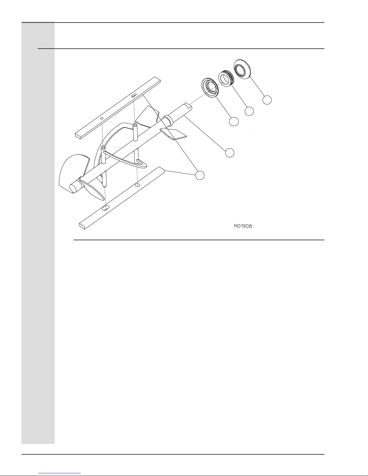
Figure 4-2 Beater Shaft
The following part names and descriptions refer to gure 4-2.
1.) SHAFT-BEATER:
Rotates in the
freezing cylinder, blending air and
mix and ejecting product.
2.) BLADE-SCRAPER:
Scrapes the
frozen product from the freezing
cylinder wall.
3.) SEAL (CUP) - BEATER SHAFT:
Seals the opening between the
freezing cylinder and the beater. DO
NOT LUBRICATE.
4.) WASHER - SHAFT SEAL:
Holds
the shaft seals together. Must be
lubricated.
8
185231-17
ELECTRO FREEZE Shake Model CS700-FG
4. Part Names and Functions — continued
O-Ring
Tube-Mix Feed
Insert-Assy. Mix
Feed
O-Ring
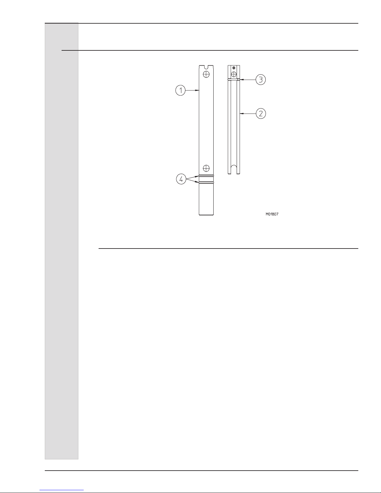
Figure 4-3 Mix Feed Tube
The following part names and descriptions refer to gure 4-3.
1.) TUBE-MIX FEED: Meters the correct
amount of mix and air into the freezing
cylinder from the hopper.
2.) INSERT- MIX FEED: Meters the correct
amount of mix and air into the freezing
cylinder from the hopper.
3.) O-RING - MIX FEED TUBE: Seals the
opening between the mix feed tube and
mix feed tube insert.
4.) O-RING-MIX FEED TUBE: Seals
the opening between the hopper and
mix feed tube. O-rings do not need
lubrication.
185231-17
9
ELECTRO FREEZE Shake Model CS700-FG
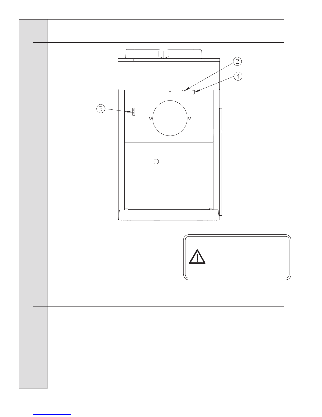
5 Operator Controls
Figure 5-1
The following paragraphs describe the
operator controls and indicators. Refer to
gure 5-1 for location of these controls
and indicators on the freezer.
NOTE: The head and actuator rod must
be in place before the beater will operate.
5.1 Selector Switch (1)
This three-position switch controls the
operating mode of your freezer.
a. “CLEAN” (left) — This
position operates the beater only (no
refrigeration). Always use this mode
when performing cleaning and sanitizing
operations.
b. “OFF” (center) — In this
position the beater motor and refrigeration
system will not operate.
CAUTION
Test operation of the head
switch prior to placing
the freezer in service.
See Section 11, Routine
Maintenance, Monthly.
Important:
Do not use the “AUTO” position with
water or sanitizer in the cylinder — the
freezer will be damaged.
c. “AUTO” (right) — This
position activates both the beater motor
and refrigeration unit. This is the normal
operating position which will maintain a
cylinder temperature of 26° to 28°F (-3° to
-2°C).
—continued
10
185231-17

ELECTRO FREEZE Shake Model CS700-FG
5 Operator Controls — continued
5.2 Reset — Circuit Breaker (2)
This control protects the beater motor
against failure from an overload condition
by automatically shutting down the
freezer. To restart properly, turn the
SELECTOR switch to “OFF”, wait 2-3
minutes, then depress the reset button
and turn the SELECTOR switch back to
the “AUTO” or “CLEAN” position.
Important:
If the circuit breaker trips frequently,
your freezer should be checked for
proper product temperature, overrun
and voltage. Contact your Electro
Freeze Distributor.
5.3 Outlet Spindle (3)
This 220v receptacle provided in the
electrical box accepts the spindle cord.
5.4 Indicator- Light — “ADD MIX” (4)
This light indicates the mix in the mix
hopper is at a low level and should be
relled as soon as possible. Always
maintain at least 2 inches (5.1 cm) of mix
in the hopper. For best operating results
keep hopper full.
5.5 Spindle Auxiliary Switch (5)
This push-button, when depressed, will
activate the spindle motor for additional
mixing of shake or during cleaning.
5.6 Mix Float (not shown)
When this oat is mounted on the
oat stem inside the mix hopper it
automatically senses the mix level. It
activates the “Add Mix” light.
185231-17
11
 Loading...