

Page 1
Bedienungsanleitung
Formatkreissäge
t
Operating Instructions
Format Circular Saw
p
Mode d’emploi
Scie circulaire à format
C
Istruzioni per l’uso
Sega circolare per squadratura
lL
Betjeningsvejledning
Formatrundsav
A
Használati utasítás
Szabványkörfűrész
Bf
Upute za uporabu
Stacionarna kružna pila
4
Uputstva za upotrebu
Stacionarna kružna testera
j
Návod k obsluze
Formátovací kotoučová pila
W
Návod na obsluhu
Formátovacia kotúčová píla
Art.-Nr.: 43.406.81 I.-Nr.: 01017
RT-CC
315 UD
Anleitung_RT_CC_315_UD_SPK1:_ 29.12.2008 15:32 Uhr Seite 1
Page 2
2
1
2
l
20
11
16
2
21
13
28
2219
28
k
3
6
18
a
b
c
d
29
30
26
14
9
25
26
27
11
12
10
6
he
f
g
j
31
i
4
5
7
8
13
20
23
24
21
14 15 161817
1
22
15
24
19
2
3
Anleitung_RT_CC_315_UD_SPK1:_ 29.12.2008 15:32 Uhr Seite 2
Page 3
3
5
3 4
7 8
6
26
l
A
21
l
a
A
k
b,c,d
25
22
22
e
h,j
g,h,i,j
f,h,i
h,j
21
e
25
6
Anleitung_RT_CC_315_UD_SPK1:_ 29.12.2008 15:32 Uhr Seite 3
Page 4
4
9 10
13 14
12
11
1.
2.
24
B
15
15
15
15
C
C
B
B
B
C
Anleitung_RT_CC_315_UD_SPK1:_ 29.12.2008 15:32 Uhr Seite 4
Page 5
5
17
15 16
D
15
D
15
D
15
18
19 20
18
28
19
27
17
19
28
E
18
F
Anleitung_RT_CC_315_UD_SPK1:_ 29.12.2008 15:32 Uhr Seite 5
Page 6
6
23
21 22
25 26
24
G
G
23
23
12
30
29
12
L
K
30
1
19
17
J
26
I
H
Anleitung_RT_CC_315_UD_SPK1:_ 29.12.2008 15:33 Uhr Seite 6
Page 7
7
29
27 28
31 32
30
3
L
4
E
2
E
3
2
2
12
A
3
B
B
K
C
12
12
5
D
5
Anleitung_RT_CC_315_UD_SPK1:_ 29.12.2008 15:33 Uhr Seite 7
Page 8
8
35
33 34
37 38
36
B
45°
13
14
G
13
H G
13
11
11
11
2
15
F
3
G
10
K
I
J
Anleitung_RT_CC_315_UD_SPK1:_ 29.12.2008 15:33 Uhr Seite 8
Page 9
9
41
39 40
43 44
42
F
F
M
L
N
16
12
15
13
L 16
16
F
15
16
a
1
15
14
M
N
L
Anleitung_RT_CC_315_UD_SPK1:_ 29.12.2008 15:33 Uhr Seite 9
Page 10
10
47
45 46
49 50
48
c
d
13 a
j
g g
I
n
m
c
8
12
3
10
k
i
b
e
2
2
4
q
f
Anleitung_RT_CC_315_UD_SPK1:_ 29.12.2008 15:33 Uhr Seite 10
Page 11
11
53
51 52
55 56
54
7
9
9
8
+
-
15
1
o
o
p
p
Anleitung_RT_CC_315_UD_SPK1:_ 29.12.2008 15:33 Uhr Seite 11
Page 12
12
59
57 58
61 62
60
8a
B
3
3
3
A
8b
3
6
c
11
15
Anleitung_RT_CC_315_UD_SPK1:_ 29.12.2008 15:33 Uhr Seite 12
Page 13
13
63 64
15
12
16
11
12
15
Anleitung_RT_CC_315_UD_SPK1:_ 29.12.2008 15:33 Uhr Seite 13
Page 14

14
D
Achtung!
Beim Benutzen von Geräten müssen einige
Sicherheitsvorkehrungen eingehalten werden, um
Verletzungen und Schäden zu verhindern. Lesen Sie
diese Bedienungsanleitung/ Sicherheitshinweise
deshalb sorgfältig durch. Bewahren Sie diese gut auf,
damit Ihnen die Informationen jederzeit zur
Verfügung stehen. Falls Sie das Gerät an andere
Personen übergeben sollten, händigen Sie diese
Bedienungsanleitung/ Sicherheitshinweise bitte mit
aus. Wir übernehmen keine Haftung für Unfälle oder
Schäden, die durch Nichtbeachten dieser Anleitung
und den Sicherheitshinweisen entstehen.
1. Sicherheitshinweise
Die entsprechenden Sicherheitshinweise finden Sie
im beiliegenden Heftchen!
WARNUNG
Lesen Sie alle Sicherheitshinweise und
Anweisungen. Versäumnisse bei der Einhaltung der
Sicherheitshinweise und Anweisungen können
elektrischen Schlag, Brand und/oder schwere
Verletzungen verursachen zur Folge haben.
Bewahren Sie alle Sicherheitshinweise und
Anweisungen für die Zukunft auf.
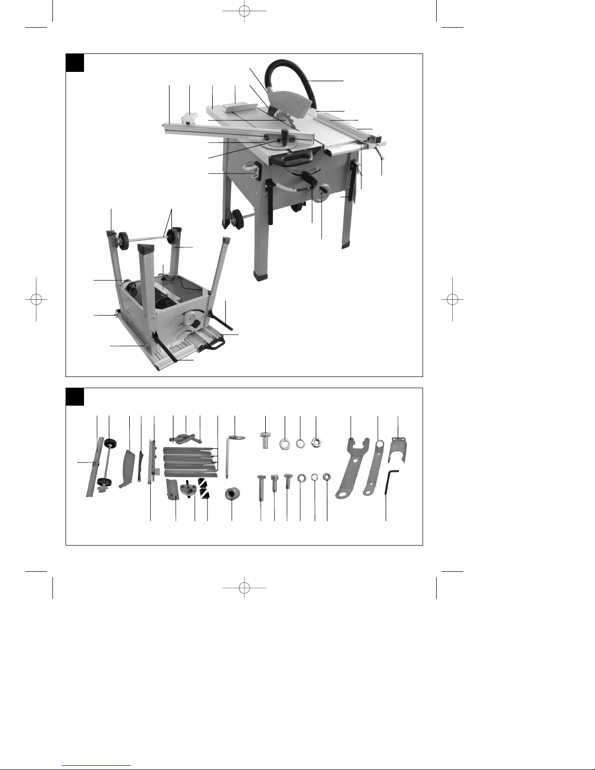
2. Gerätebeschreibung / Montagewerkzeug / Montagematerial /
Lieferumfang (Bild 1-2)
2.1 Gerätebeschreibung
1. Sägetisch
2. Anschlagschiene für Parallelanschlag
3. Parallelanschlag
4. Klemmhebel für Parallelanschlag
5. Führungsschiene für Parallelanschlag
6. Schiebestock
7. Handkurbel für Sägeblatthöhe
8. Feststellgriff für Sägeblattneigung
9. Ein-/Aus-/Not-Aus-Schalter
10. Klemmgriff für Queranschlag
11. Queranschlag
12. Sägeblatt
13. Anschlagschiene für Queranschlag
14. Verschiebbarer Endanschlag
15. Schiebetisch
16. Besäumungs-Hilfsblech
17. Spaltkeil
18. Sägeblattschutz
19. Absaugschlauch
20. Gummifüße
21. Fahrgestell
22. Standbeine
23. Spänekasten
24. Fahrgriffe
25. Haken für Werkzeug
26. Halterung für Absaugschlauch
27. Absaugadapter
28. Schlauchschellen für Absaugschlauch
2.2 Montagewerkzeug
29. Flanschschlüssel
30. Schraubenschlüssel
31. Inbusschlüssel
2.3 Montagematerial
a 16 x Schraube für Standbeine (M10 x 20mm)
b 16 x Beilagscheibe für Standbeine (M10)
c 16 x Sprengring für Standbeine (M10)
d 16 x Mutter für Standbeine (M10)
e 4 x Schraube für Fahrgestell (M8 x 35mm)
f 2 x Inbus-Schraube für Halterung
Absaugschlauch (M8 x 20mm)
g 4 x Schraube für Befestigungswinkel (M8 x
20mm)
h 14 x Beilagscheibe (M8)
i 4 x Sprengring (M8)
j 8 x Mutter (M8)
k 4 x Metallwinkel
l 4 x Distanzstück
2.4 Lieferumfang
Formatkreissäge
Parallelanschlag (3) mit Anschlagschiene (2)
Schiebestock (6)
Queranschlag (11)
Anschlagschiene für Queranschlag (13)
Besäumungs-Hilfsblech (16)
Sägeblattschutz (18)
Absaugschlauch (19) mit 2 Schlauchschellen
(28)
4 x Gummifüße (20)
Fahrgestell (21)
4 x Standbeine (22)
Halterung für Absaugschlauch (26)
Montagewerkzeug (siehe Punkt 2.2)
Montagematerial (siehe Punkt 2.3)
3. Bestimmungsgemäße Verwendung
Die Tischkreissäge dient zum Längs- und
Querschneiden (nur mit Queranschlag) von Hölzern
entsprechend der Maschinengröße.
Rundhölzer aller Art dürfen nicht geschnitten
werden.
Anleitung_RT_CC_315_UD_SPK1:_ 29.12.2008 15:33 Uhr Seite 14
Page 15
15
D
Die Maschine darf nur nach ihrer Bestimmung
verwendet werden. Jede weitere darüber
hinausgehende Verwendung ist nicht
bestimmungsgemäß. Für daraus hervorgerufene
Schäden oder Verletzungen aller Art haftet der
Benutzer/Bediener und nicht der Hersteller.
Bitte beachten Sie, dass unsere Geräte
bestimmungsgemäß nicht für den gewerblichen,
handwerklichen oder industriellen Einsatz konstruiert
wurden. Wir übernehmen keine Gewährleistung,
wenn das Gerät in Gewerbe-, Handwerks- oder
Industriebetrieben sowie bei gleichzusetzenden
Tätigkeiten eingesetzt wird.
4. Technische Daten
Wechselstrommotor 400V 3 ~ 50Hz
Leistung P 1800 Watt S1 2200 Watt S6 40%
Leerlaufdrehzahl n
0
2750 min
-1
Hartmetallsägeblatt Ø 315 x Ø 30 x 3,6 mm
Anzahl der Zähne 24
Größe Haupttisch 800 x 350 mm
Größe Schiebetisch 1000 x 300 mm
Schiebelänge max. 600 mm
Schnitthöhe max. 73 mm / 0°
49 mm / 45°
Höhenverstellung stufenlos 0 - 73 mm
Sägeblatt schwenkbar stufenlos 0° - 45°
Absauganschluss Ø 100 mm
Gewicht: 52 kg
Betriebsart S1: Dauerbetrieb
Betriebsart S6 40%: Durchlaufbetrieb mit
Aussetzbelastung (Spieldauer 10 min). Um den
Motor nicht unzulässig zu erwärmen darf der Motor
40% der Spieldauer mit der angegebenen
Nennleistung betrieben werden und muss
anschließend 60% der Spieldauer ohne Last
weiterlaufen.
Geräuschemissionswerte
Betrieb Leerlauf
Schalldruckpegel L
pA
90,6 dB 78,1 dB
Schalleistungspegel L
WA
105,1 dB 92,5 dB
Die angegebenen Werte sind Emissionswerte und
müssen damit nicht zugleich auch sichere
Arbeitsplatzwerte darstellen. Obwohl es eine
Korrelation zwischen Emissions- und
Immissionspegeln gibt, kann daraus nicht zuverlässig
abgeleitet werden, ob zusätzliche
Vorsichtsmaßnahmen notwendig sind oder nicht.
Faktoren, welche den derzeitigen am Arbeitsplatz
vorhandenen Immissionspegel beeinflussen können,
beinhalten die Dauer der Einwirkungen, die Eigenart
des Arbeitsraumes, andere Geräuschquellen usw.,
z.B. die Anzahl der Maschinen und anderen
benachbarten Vorgängen.
Die zuverlässigen Arbeitsplatzwerte können ebenso
von Land zu Land variieren. Diese Information soll
jedoch den Anwender befähigen, eine bessere
Abschätzung von Gefährdung und Risiko
vorzunehmen.
5. Vor Inbetriebnahme
Dieses Gerät darf nur von einer Fachkraft oder
einer anderen, ähnlich qualifizierten Person
montiert werden.
Überzeugen Sie sich vor dem Anschließen, dass
die Daten auf dem Typenschild mit den
Netzdaten übereinstimmen.
Überprüfen Sie regelmäßig den Mikroschalter
des Schiebetisches auf korrekte Funktion! Die
Säge darf nur bei korrekt montiertem
Schiebetisch betrieben werden.
Tischkreissäge auspacken und auf eventuelle
Transportbeschädigungen überprüfen.
Vor Inbetriebnahme müssen alle Abdeckungen
und Sicherheitsvorrichtungen ordnungsgemäß
montiert sein.
Das Sägeblatt muss frei laufen können.
Bei bereits bearbeitetem Holz auf Fremdkörper
wie z.B. Nägel oder Schrauben usw. achten.
Bevor Sie den Ein-/Aus-/Not-Aus-Schalter (9)
betätigen, vergewissern Sie sich, ob das
Sägeblatt richtig montiert ist und bewegliche
Teile leichtgängig sind.
Überprüfen Sie den Lieferumfang auf
Vollständigkeit (siehe Punkt 2.4).
5.1 Montage
Achtung! Vor allen Wartungs- Umrüst- und
Montagearbeiten an der Kreissäge ist der
Netzstecker zu ziehen.
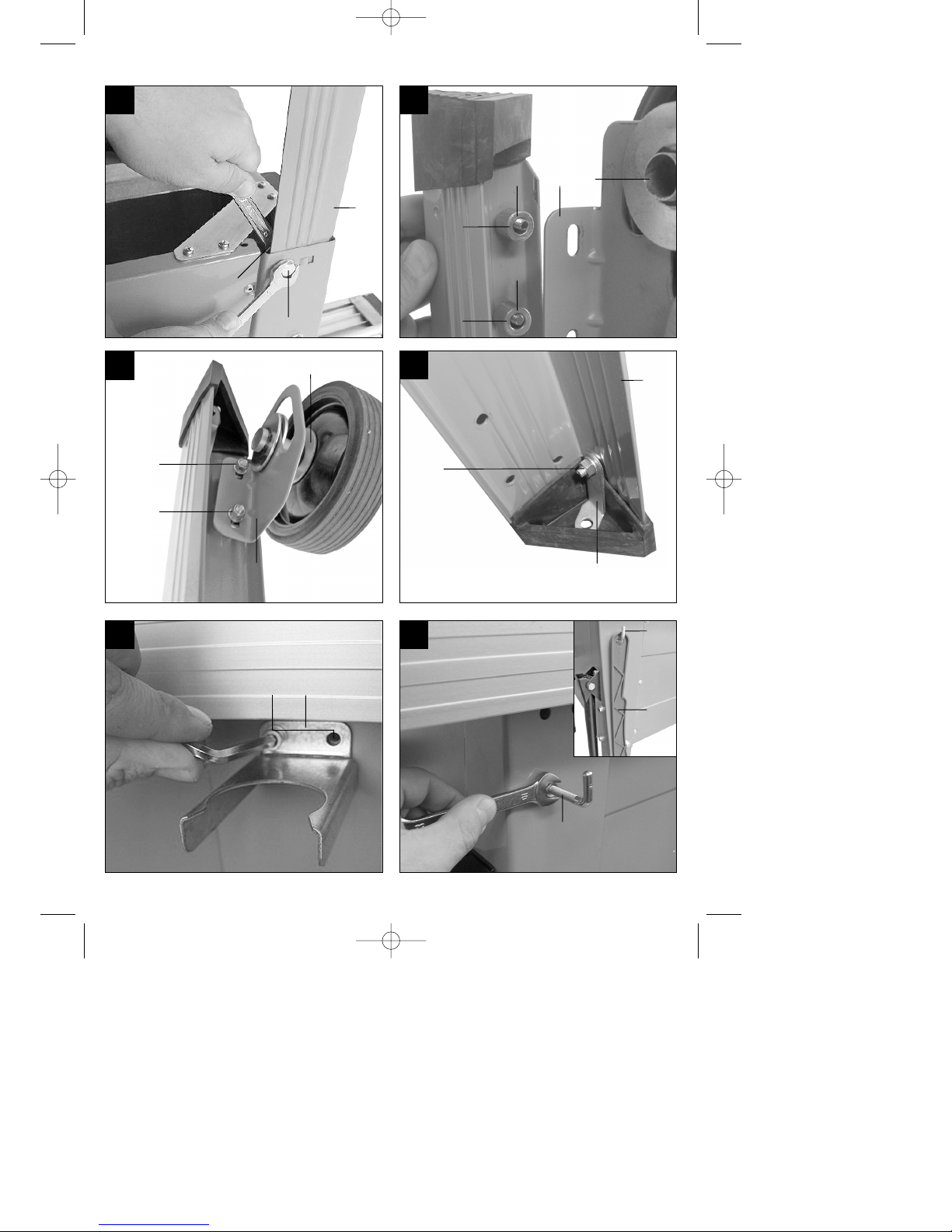
5.1.1 Säge aufbauen, Untergestell und Fahrgestell
montieren (Bild 1-8)
Säge mit dem Tisch nach unten auf eine ebene
Unterlage legen.
Anleitung_RT_CC_315_UD_SPK1:_ 29.12.2008 15:33 Uhr Seite 15
Page 16

16
D
Die vier Standbeine (22) mit jeweils vier
Schrauben, Beilagscheiben, Sprengringen und
Muttern (a, b, c, d) von innen an den
Maschinenkörper schrauben. Bein Einstecken
der Standbeine darauf achten, dass die Laschen
der Standbeine zur Form der dafür
vorgesehenen Aufnahmen passen (Bild 3).
Die vier Gummifüße (20) auf die Standbeine (22)
aufstecken.
Das Fahrgestell (21) mit jeweils 2 Schrauben,
Beilagscheiben und Muttern (e, h, j) innen an die
Standbeine (22) schrauben. Dabei müssen die 4
Distanzstücke (l) zwischen den Standbeinen (22)
und den Befestigungswinkeln (A) des
Fahrgestells (21) eingefügt werden. Bei der
Montage darauf achten, dass die Rundungen der
Befestigungswinkel (A) nach unten zeigen.
(Bild 4-5)
Schrauben Sie die Metallwinkel (k) mit den
Schrauben, Beilagscheiben, Sprengringen und
Muttern (g, h, i, j) an den Standbeinen (22) fest
(Bild 6).
Säge umdrehen und auf den Boden stellen.
Halterung für den Absaugschlauch (26) mit den
Schrauben, Beilagscheiben und Muttern (f, h, j)
am Maschinenkörper festschrauben und Haken
für Werkzeug (25) anziehen. Hängen Sie den
Schiebestock (6) am Haken für Werkzeug (25)
auf (siehe Bild 7 - 8).
Die Maschine muss standsicher aufgestellt wer-
den, d. h. die Säge muss mit den Metallwinkeln,
die sich an allen vier Standbeinen (Bild 6) befinden, sicher am Boden festgeschraubt werden.
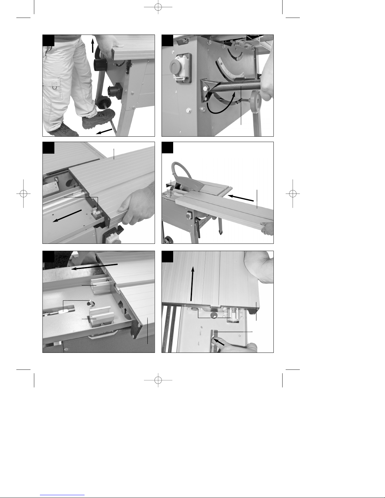
5.1.2 Verwenden des Fahrgestelles
(Bild 9-10/Pos. 21)
Zum Ausklappen des Fahrgestells die Säge an
der Rückseite leicht anheben (Bild 9/1.) und das
Fahrgestell (21) nach vorne ziehen (Bild 9/2.).
Die Tischkreissäge in dieser Position wieder
absenken.
Die Tischkreissäge steht nun auf den Rädern
und kann mit Hilfe der Fahrgriffe (24) von einer
Person transportiert werden (Bild 10).
Achtung: Säge niemals am Schiebetisch
anheben!
Achtung: Nach dem Transport muss das
Fahrgestell (21) sofort wieder eingeklappt
werden, um einen sicheren Stand der Säge zu
Gewährleisten.
Dazu Räder in umgekehrter Reihenfolge wieder
in Ausgangsposition bringen.
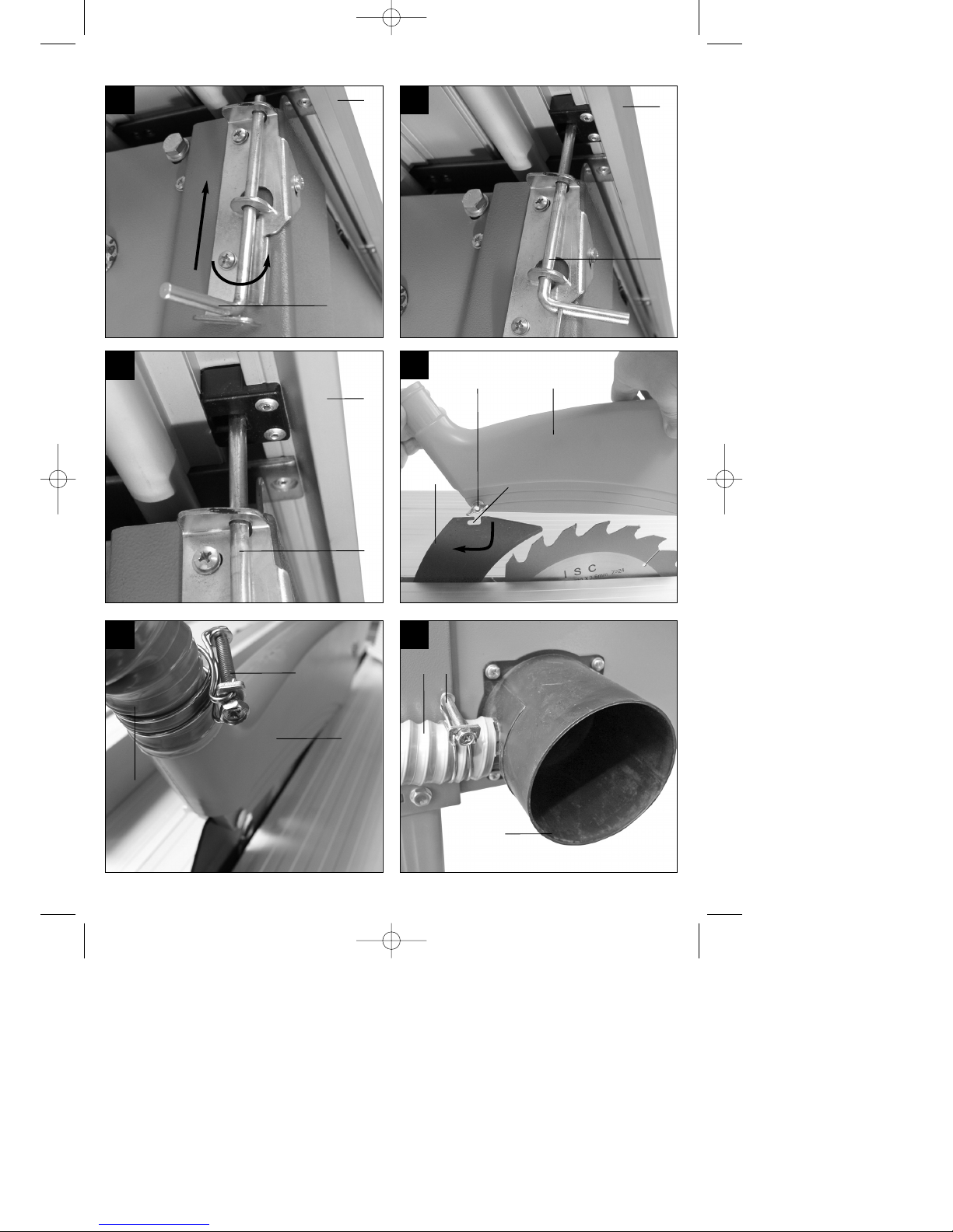
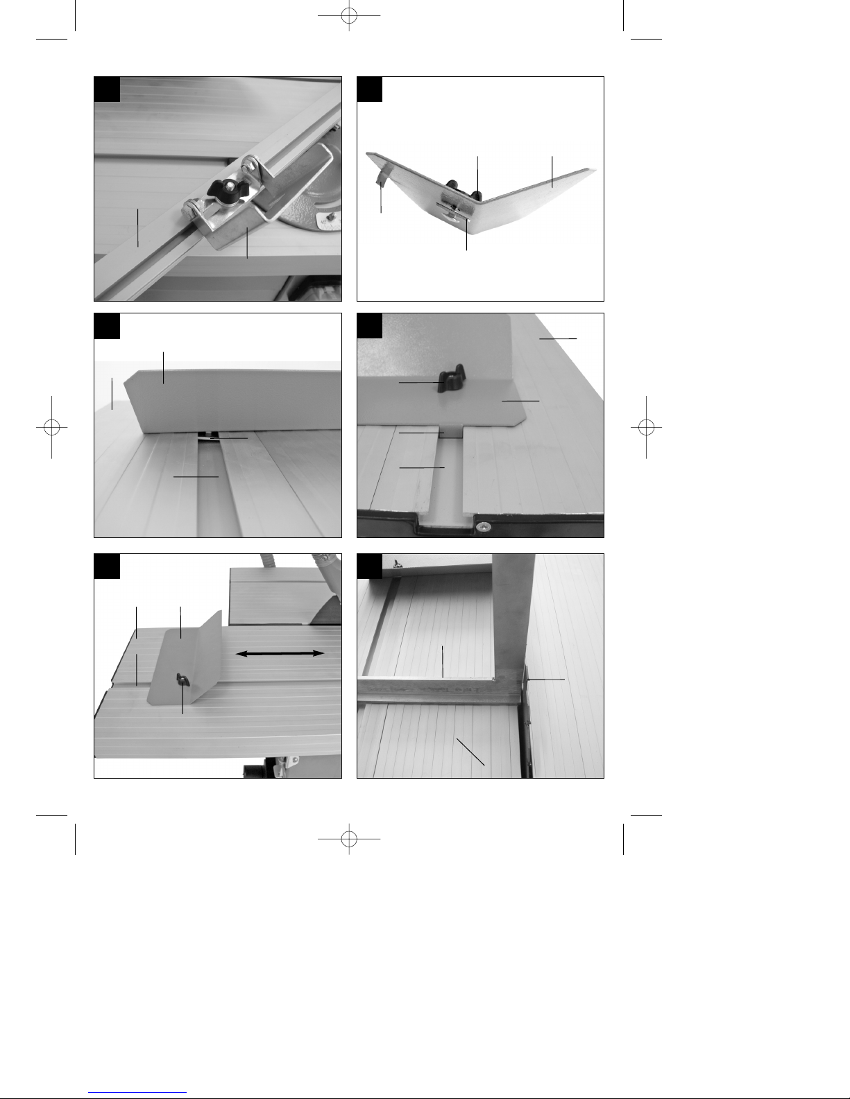
5.1.3 Schiebetisch montieren / demontieren /
arretieren (Bild 11-17/Pos. 3)
Schiebetisch (15) vorsichtig in die Gleitführungen
(B) einführen nach vorne schieben, bis der
Verriegelungshaken (C) einrastet. (Bild 11 - 13).
Zum demontieren des Schiebetisches (15) den
Schiebetisch (15) nach vorne ziehen, bis der
Verriegelungshaken (C) sichtbar ist.
Mit einer Hand von oben auf den
Verriegelungshaken (C) drücken und mit der
anderen Hand gleichzeitig den Schiebetisch (15)
nach vorne aus der Gleitführung (B)
herausziehen (Bild 14)!
Zum arretieren des Schiebetisches (15) diesen
so weit nach hinten schieben, dass sich der
Hebel für Tischarretierung (D) unterhalb der
dafür vorgesehenen Aussparung an der
Unterseite des Schiebetisches (15) befindet.
Hebel für Tischarretierung (D) nach oben
Schieben und durch Rechtsdrehung arretieren
(Bild 15 – 17).
Kontrollieren Sie ob der Hebel für
Tischarretierung (D) ordentlich eingerastet und
der Schiebetisch (15) arretiert ist.
Zum Lösen des Schiebetisches (15)
Tischarretierung (D) durch Lösen des Hebels
entsperren.
5.1.4 Sägeblattschutz montieren / demontieren
(Bild 18/Pos. 18)
Sägeblattschutz (18) auf den Spaltkeil (17)
aufsetzen, so dass die Schraube (E) durch das
Loch (F) des Spaltkeils (17) passt.
Schraube (E) nicht zu fest anziehen; der
Sägeblattschutz (18) muss frei beweglich
bleiben.
Achtung!
Vor Sägebeginn muss der Sägeblattschutz (18)
auf das Sägegut abgesenkt werden.
5.1.5 Absaugschlauch montieren
(Bild 19-21/Pos. 19)
Absaugschlauch (19) auf den Absaugadapter
(27) und den Absaugstutzen des
Sägeblattschutzes (18) stecken und mit den
Schlauchschellen für Absaugschlauch (28)
sichern.
Absaugschlauch (19) an Halterung für
Absaugschlauch (26) befestigen.
Am Ausgang des Absaugadapters (27) ist eine
geeignete Absauganlage anzuschließen.
Die Demontage erfolgt in umgekehrter
Reihenfolge.
Anleitung_RT_CC_315_UD_SPK1:_ 29.12.2008 15:33 Uhr Seite 16
Page 17

17
D
5.2 Spänekasten öffnen / Spaltkeil einstellen /
Sägeblatt wechseln (Bild 22-23)
5.2.1 Spänekasten öffnen (Bild 22/Pos. 23)
Sägeblattschutz (18) demontieren (siehe Punkt
5.1.4).
Schiebetisch (15) demontieren (siehe Punkt
5.1.3).
Zum Öffnen des Spänekastens (23) die beiden
Schrauben (G) entfernen und den Spänekasten
(23) aufklappen. Tip: Zum leichteren entfernen
der Schrauben (G) einen Winkel von ca. 30°
einstellen (siehe 6.1.3).
Die Montage erfolgt in umgekehrter Reihenfolge.
Achten Sie beim Schließen des Spänekastens
(23) darauf, dass der Schaltstift (H) in die dafür
vorgesehene Öffnung am Mikroschalter (I)
gleitet.
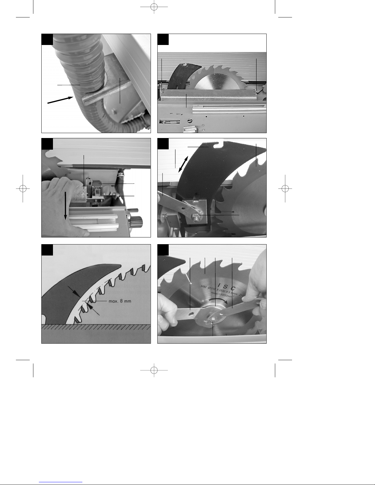
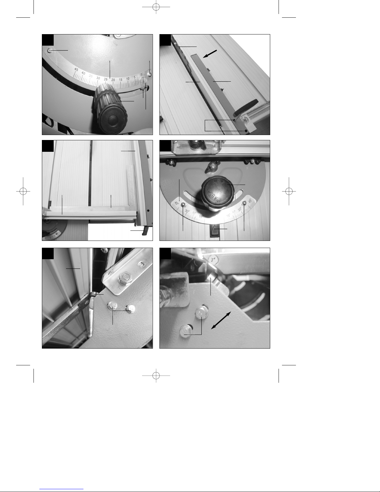
5.2.2 Spaltkeil einstellen (Bild 24-25/Pos. 17)
Achtung! Netzstecker ziehen
Sägeblatt (12) auf maximale Schnitttiefe
einstellen und arretieren (siehe 6.1.2)
Spänekasten (23) öffnen (siehe 5.2.1).
Die Mutter (J) mit dem Schraubenschlüssel (30)
lockern.
Spaltkeil (17) nach oben ziehen, bis der Abstand
zwischen Sägetisch (1) und Oberkante Spaltkeil
(17) maximal ist (Bild 24).
Der Abstand zwischen Sägeblatt (12) und
Spaltkeil (17) darf maximal 8 mm betragen (Bild
24-25).
Die Mutter (J) wieder festziehen und
Spänekasten (23) wieder montieren (siehe
5.2.1).
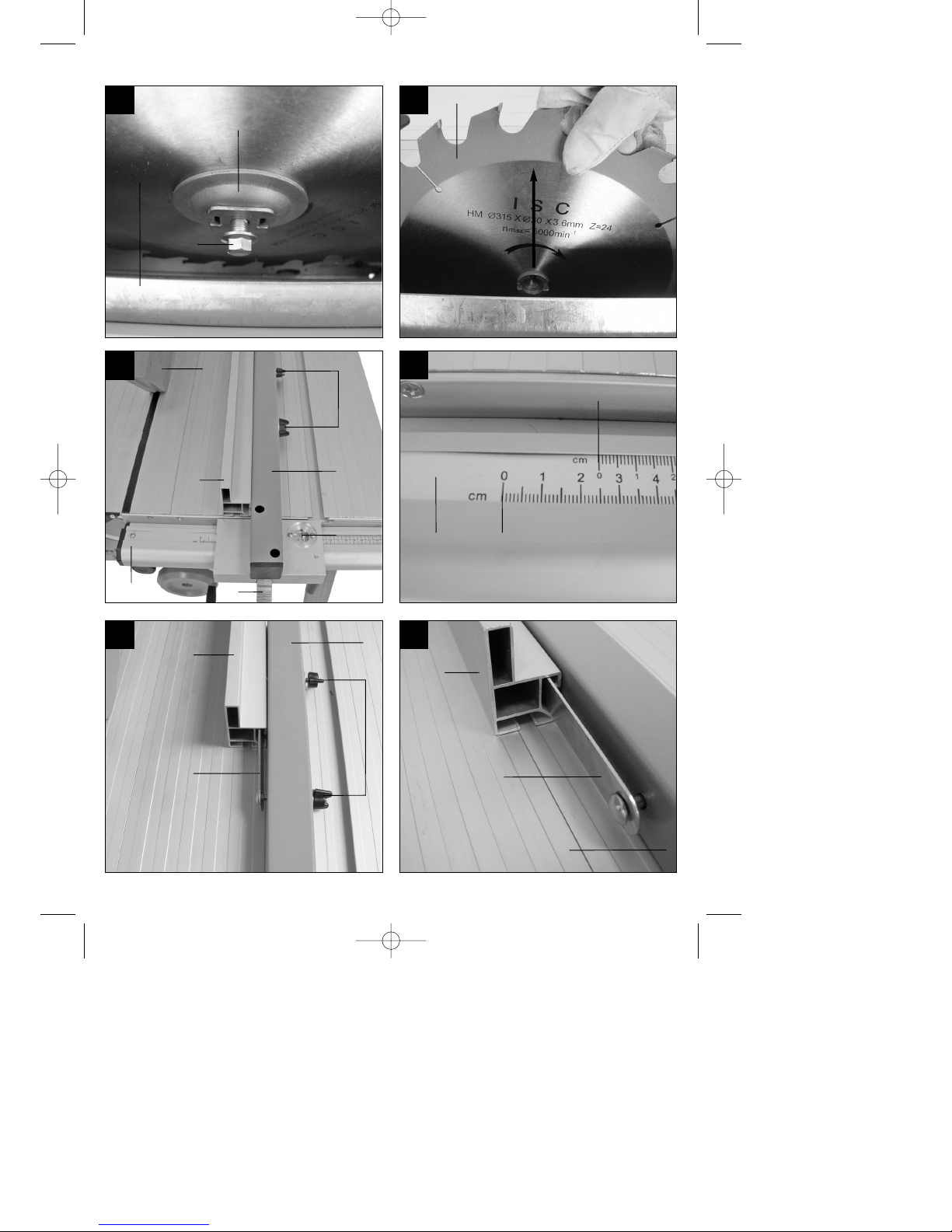
5.2.3 Sägeblatt wechseln (Bild 26-28/Pos. 12)
Achtung! Netzstecker ziehen. Tragen Sie
beim Umgang mit Sägeblättern stets
Schutzhandschuhe.
Sägeblatt (12) auf maximale Schnitttiefe
einstellen (siehe 6.1.2).
Spänekasten (23) öffnen (siehe Punkt 5.2.1).
Spaltkeil (17) demontieren (siehe Punkt 5.2.2).
Flanschschlüssel (29) am Sägeblattflansch (K)
ansetzen.
Flanschschraube (L) mit dem
Schraubenschlüssel (30) in Laufrichtung des
Sägeblattes (12) herausdrehen (Bild 26).
Flanschschraube (L) und Sägeblattflansch (K)
abnehmen (Bild 27).
Sägeblatt (12) von Innenflansch abnehmen und
nach oben herausziehen (Bild 28).
Sägeblattflansche vor der Montage des neuen
Sägeblattes (12) sorgfältig reinigen.
Das neue Sägeblatt (12) in umgekehrter
Reihenfolge wieder einsetzen und festziehen.
Achtung! Laufrichtung beachten, die
Schnittschräge der Zähne muss in Laufrichtung,
d.h. nach vorne zeigen (siehe Pfeil auf dem
Spänekasten).
Spaltkeil (17) wieder montieren und einstellen
(siehe Punkt 5.2.2).
Spänekasten (23) schließen (siehe Punkt 5.2.1).
Sägeblattschutz (18) und Schiebetisch (15)
wieder montieren und einstellen
(siehe Punkt 5.1.3-5.1.4).
Bevor Sie mit der Säge wieder arbeiten, ist die
Funktionsfähigkeit der Schutzeinrichtungen zu
prüfen.
5.3 Anschläge
5.3.1 Parallelanschlag
5.3.1.1 Anschlaghöhe (Bild 29 – 33)
Die Anschlagschiene (2) des Parallelanschlages
(3) besitzt zwei verschieden hohe
Führungsflächen.
Je nach Dicke der zu schneidenden Materialien
muss die Anschlagschiene (2) nach Abb. 29, für
dickes Material und nach Abb. 33 für dünnes
Material verwendet werden.
5.3.1.2Anschlagschiene drehen
(Bild 31-33/Pos. 2)
Lockern Sie zum Drehen der Anschlagschiene
(2) zuerst die Flügelmuttern (B).
Nun kann die Anschlagschiene (2) von der
Führungsschiene (E) abgezogen und mit der
entsprechenden Führung wieder über diese
geschoben werden.
Ziehen Sie die Flügelmuttern (B) wieder an.
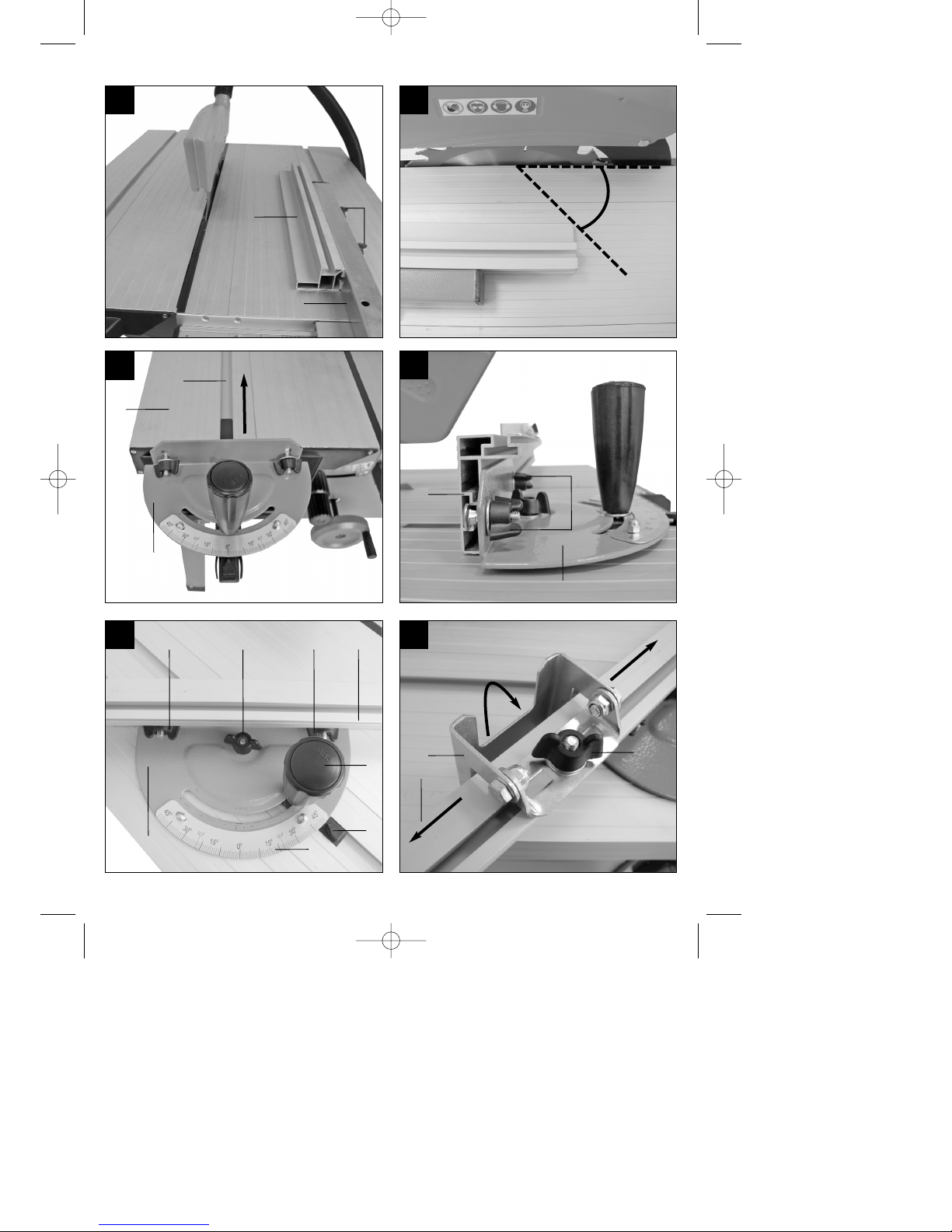
5.3.1.3 Schnittbreite (Bild 29 - 30)
Beim Längsschneiden von Holzteilen muss der
Parallelanschlag (3) verwendet werden.
Der Parallelanschlag (3) sollte auf der rechten
Seite des Sägeblattes (12) montiert werden.
Den Parallelanschlag (3) von oben auf die
Führungsschiene für Parallelanschlag (5) setzen
(Bild 29).
Auf der Führungsschiene für Parallelanschlag (5)
befinden sich 2 Skalen (C/D), welche den
Abstand zwischen Anschlagschiene (2) und
Sägeblatt (12) anzeigen (Bild 30).
Wählen Sie abhängig davon, ob die
Anschlagschiene (2) für die Bearbeitung von
dickem oder dünnem Material gedreht ist die
passende Skala:
Anleitung_RT_CC_315_UD_SPK1:_ 29.12.2008 15:33 Uhr Seite 17
Page 18
Hohe Anschlagschiene (dickes Material):
Skala D
Niedrige Anschlagschiene (dünnes Material):
Skala C
Parallelanschlag (3) auf das gewünschte Maß
am Schauglas (A) einstellen und mit dem
Klemmhebel für Parallelanschlag (4) fixieren.
5.3.1.4 Anschlaglänge einstellen (Bild 29, 34)
Um das Klemmen des Schnittgutes zu
vermeiden, ist die Anschlagschiene (2) in
Längsrichtung verschiebbar.
Faustregel: Das hintere Ende des Anschlages
stößt an eine gedachte Linie, die etwa bei der
Sägeblattmitte beginnt und unter 45° nach hinten
verläuft.
Benötigte Schnittbreite einstellen.
Flügelmuttern (B) lockern und Anschlagschiene
(2) so weit vorschieben, bis die gedachte 45°
Linie berührt wird.
Flügelmuttern (B) wieder festziehen.
5.3.2 Queranschlag
5.3.2.1 Montage Queranschlag (Bild 35 - 37)
Klemmgriff für Queranschlag (10) und
Flügelmutter (H) lockern.
Queranschlag (11) in die Nut (F) des
Schiebetisches (15) schieben (Bild 35, 37).
Flügelmuttern (G) lockern und Anschlagschiene
für Queranschlag (13) über die Schraubenköpfe
an der Rückseite des Queranschlages (11)
führen (Bild 36).
5.3.2.2 Anschlaghöhe (Bild 36)
Die Anschlagschiene für Queranschlag (13)
besitzt zwei verschieden hohe Führungsflächen.
Je nach Dicke der zu schneidenden Materialien
muss die Anschlagschiene gedreht werden.
Wählen Sie die entsprechende Anschlaghöhe
und montieren Sie sie wie in den Punkten 5.3.1.1
bzw. 5.3.1.2 für den Parallelanschlag
beschrieben.
5.3.2.3 Winkeleinstellung Queranschlag (Bild 37)
Klemmgriff für Queranschlag (10) und
Flügelmutter (H) lockern.
Queranschlag (11) drehen, bis der Zeiger (I) auf
das gewünschte Winkelmaß an der Skala (J)
zeigt.
Klemmgriff für Queranschlag (10) und
Flügelmutter (H) wieder anziehen.
5.3.2.4Längseinstellung des Parallelanschlages
auf dem Schiebetisch (Bild 37)
Klemmgriff für Queranschlag (10) und
Flügelmutter (H) lockern.
Queranschlag (11) in die gewünschte Position
schieben.
Klemmgriff für Queranschlag (10) und
Flügelmutter (H) wieder anziehen.
5.3.2.5Einstellen der Anschlagschiene für
Queranschlag (Bild 37)
Flügelmuttern (G) lockern.
Anschlagschiene für Queranschlag (13) quer
verschieben bis die gewünschte Position erreicht
ist.
Flügelmuttern (G) wieder anziehen.
Achtung!
Anschlagschiene für Queranschlag (13) nicht zu
weit in Richtung Sägeblatt (12) schieben.
Der Abstand zwischen Anschlagschiene für
Queranschlag (13) und Sägeblatt (12) sollte ca.
2 cm betragen.
5.3.3 Verschiebbarer Endanschlag (Bild 38-39)
Um das Ablängen mehrerer gleich langer
Werkstücke zu vereinfachen, ist die
Anschlagschiene für Queranschlag (13) mit
einem Verschiebbaren Endanschlag (14)
ausgestattet.
Lösen Sie die Flügelmutter (K), schieben sie den
Verschiebbaren Endanschlag (14) in die
gewünschte Position auf der Anschlagschiene
für Queranschlag (13) und ziehen Sie die
Flügelmutter (K) wieder an.
Der Verschiebbare Endanschlag (14) kann nach
oben geklappt werden, um z.B. zuerst die
Kanten des Werkstücks gerade abzuschneiden,
das Werkstück zu drehen und dann mit dem
herunter geklappten Endanschlag (14) auf die
passende Länge zu schneiden.
Der Verschiebbare Endanschlag (14) kann von
der Anschlagschiene für Queranschlag (13)
abgenommen werden, indem die Flügelmutter
(K) gelockert und der Verschiebbare
Endanschlag (14) von der Anschlagschiene für
Queranschlag (13) abgezogen wird.
Die Montage erfolgt in umgekehrter Reihenfolge.
5.3.4 Besäumungs-Hilfsblech (Bild 40-43)
Das Besäumungs-Hilfsblech (16) dient als
Endanschlag beim Besäumen.
Montieren Sie das Besäumungs-Hilfsblech (16)
entsprechend den Abbildungen 40 – 43 am
Schiebetisch (15).
Achten Sie darauf, dass das Metallplättchen (N)
und die Führungsnase (M) in der Nut (F) des
18
D
Anleitung_RT_CC_315_UD_SPK1:_ 29.12.2008 15:33 Uhr Seite 18
Page 19

Schiebetisches (15) sitzen.
Schieben Sie das Besäumungs-Hilfsblech (16) in
die gewünschte Position, und fixieren Sie es,
indem Sie die Flügelmutter (L) anziehen.
5.4 Justieren der Säge
Achtung! Da es sich bei dieser Säge um ein
Präzisionswerkzeug handelt, kann es nach Montage
bzw. Aufstellung erforderlich sein, die Säge
nachzujustieren. Gehen Sie hierbei bitte nach
folgender Anleitung vor.
5.4.1. Justierung Sägeblatt (Bild 44-45)
Richten Sie das Sägeblatt (12) mittels
Anschlagwinkel (a) und Feststellgriff für
Sägeblattneigung (8) so aus, dass es in einem
Winkel von 90° zum Sägetisch (1) steht. Überprüfen
Sie, ob der Zeiger (b) auf 0° steht. Wenn nicht, lösen
Sie die beiden Schrauben (c) und justieren die Skala
(d) so, dass der Zeiger (b) auf 0° zeigt. Fixieren Sie
die Skala (d) anschließend wieder mit den beiden
Schrauben. Kleinere Abweichungen können auch
dadurch korrigiert werden, dass Sie die Schraube (e)
lockern und den Zeiger (b) verstellen.
5.4.2. Justierung Parallelanschlag (Bild 46-47)
Schieben Sie den Parallelanschlag (3) nach links, bis
die Anschlagschiene für Parallelanschlag (2) das
Sägeblatt (12) berührt, und arretieren ihn dann mit
dem Klemmhebel für Parallelanschlag (4).
Überprüfen Sie, ob die Anschlagschiene für
Parallelanschlag (2) parallel zum Sägeblatt (12)
verläuft. Wenn nicht, lösen Sie die beiden InbusSchrauben (f) und richten den Parallelanschlag (3)
so aus, dass die Anschlagschiene für
Parallelanschlag (2) parallel zum Sägeblatt (12)
verläuft. Fixieren Sie den Parallelanschlag (3)
anschließend wieder mit den beiden InbusSchrauben (f).
5.4.3. Justierung Queranschlag (Bild 47-48)
Lösen Sie den Klemmgriff für Queranschlag (10) und
richten Sie die Anschlagschiene für Queranschlag
(13) mittels Anschlagwinkel (A), wie in Bild 47
gezeigt, im 90°-Winkel zur Anschlagschiene für
Parallelanschlag (2) aus. Überprüfen Sie, ob der
Zeiger (i) auf 0° zeigt. Wenn nicht, lösen Sie die
beiden Schrauben (g) und justieren die Skala (j) so,
dass der Zeiger (i) auf 0° zeigt. Fixieren Sie die
Skala (j) anschließend wieder mit den beiden
Schrauben (g).
5.4.4. Justierung Schiebetisch (Bild 48-53)
Überprüfen Sie, wie in Bild 51 gezeigt, ob der
Schiebetisch (15) plan zum Sägetisch (1) ist. Wenn
nicht, lösen Sie die beiden Schrauben (o) bzw. (p) an
der Vorder- und Rückseite und richten den
Schiebetisch (15) plan zum Sägetisch (1) aus.
Fixieren Sie den Schiebetisch (15) anschließend
wieder mit den vier Schrauben (o bzw. p). Der
Sägetisch (1) verfügt über zwei Kugellager (k/m), die
das Gleiten des Tisches unterstützen. Überprüfen
Sie an Vorder- und Rückseite der Säge, ob die
Kugellager die Führungsschiene (q) berühren. Wenn
nicht, lösen Sie die Schrauben (l) bzw. (n) und
richten Sie die Kugellager (k/m) so aus, dass sie die
Führungsschiene (q) berühren. Fixieren Sie die
Kugellager (k/m) anschließend wieder mit den
beiden Schrauben (l/n).
6. Bedienung
Achtung!!
Nach jeder neuen Einstellung empfehlen wir
einen Probeschnitt, um die eingestellten Maße
zu überprüfen.
Nach den Einschalten der Säge abwarten, bis
das Sägeblatt seine maximale Drehzahl erreicht
hat, bevor Sie den Schnitt durchführen.
Achtung beim Einschneiden!
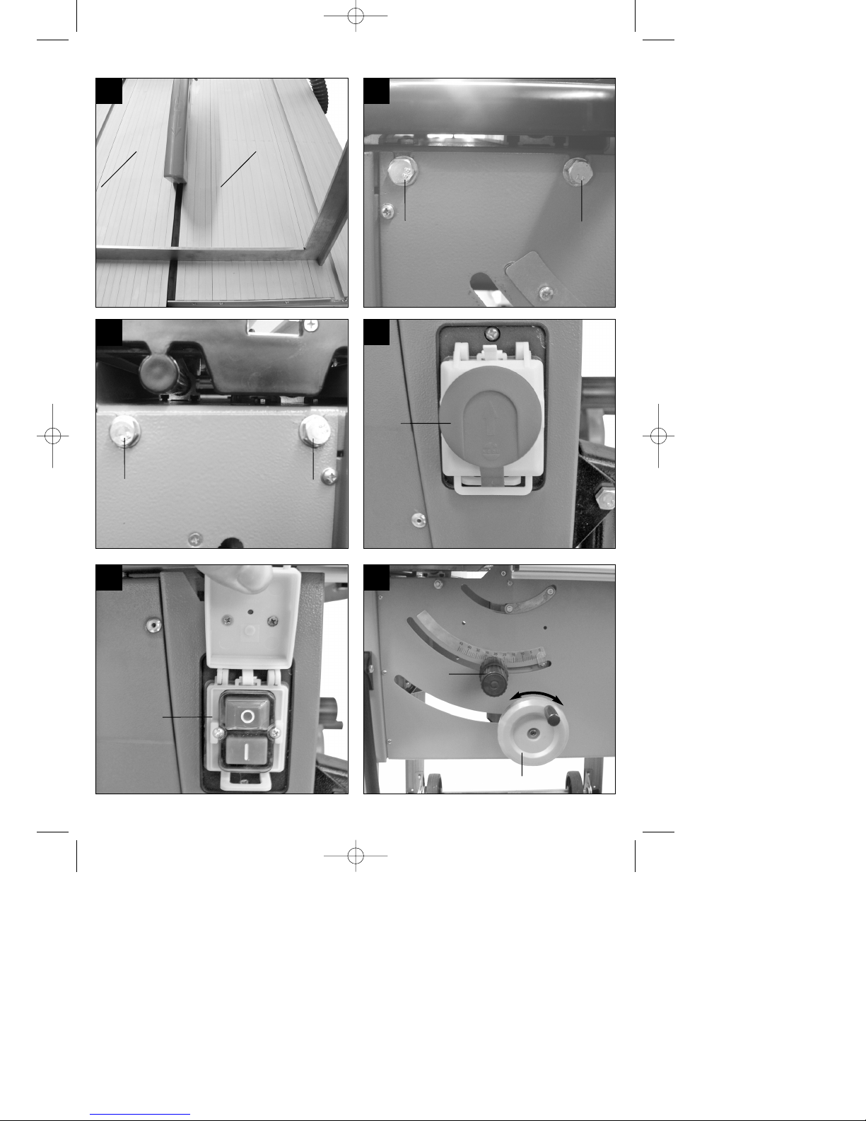
6.1 Bedienelemente
6.1.1 Ein-/Aus-/Not-Aus-Schalter
(Bild 54-55/Pos. 9)
Klappen Sie die Abdeckung des Ein-/Aus-/Not-
Aus-Schalters (9) nach oben.
Durch Drücken der grünen Taste „1“ kann die
Säge eingeschaltet werden.
Um die Säge wieder auszuschalten, muss die
rote Taste „0“ gedrückt werden.
Achtung!
Die Säge ist mit einer Not-Aus Funktion ausgestattet.
Drücken Sie zum schnellen und einfachen
Ausschalten der Maschine auf die Klappe des Ein/Aus-/Not-Aus-Schalters (Bild 54/Pos. 9).
6.1.2 Einstellen der Schnitttiefe (Bild 56)
Durch Drehen der Handkurbel für Sägeblatthöhe
(7), kann das Sägeblatt (12) auf die gewünschte
Schnitttiefe eingestellt werden.
Drehen sie die Handkurbel für Sägeblatthöhe (9):
Entgegen dem Uhrzeigersinn:
größere Schnitttiefe
Im Uhrzeigersinn:
kleinere Schnitttiefe
19
D
Anleitung_RT_CC_315_UD_SPK1:_ 29.12.2008 15:33 Uhr Seite 19
Page 20

Achtung!
Nehmen Sie diese Einstellung nur bei
ausgeschalteter Maschine vor.
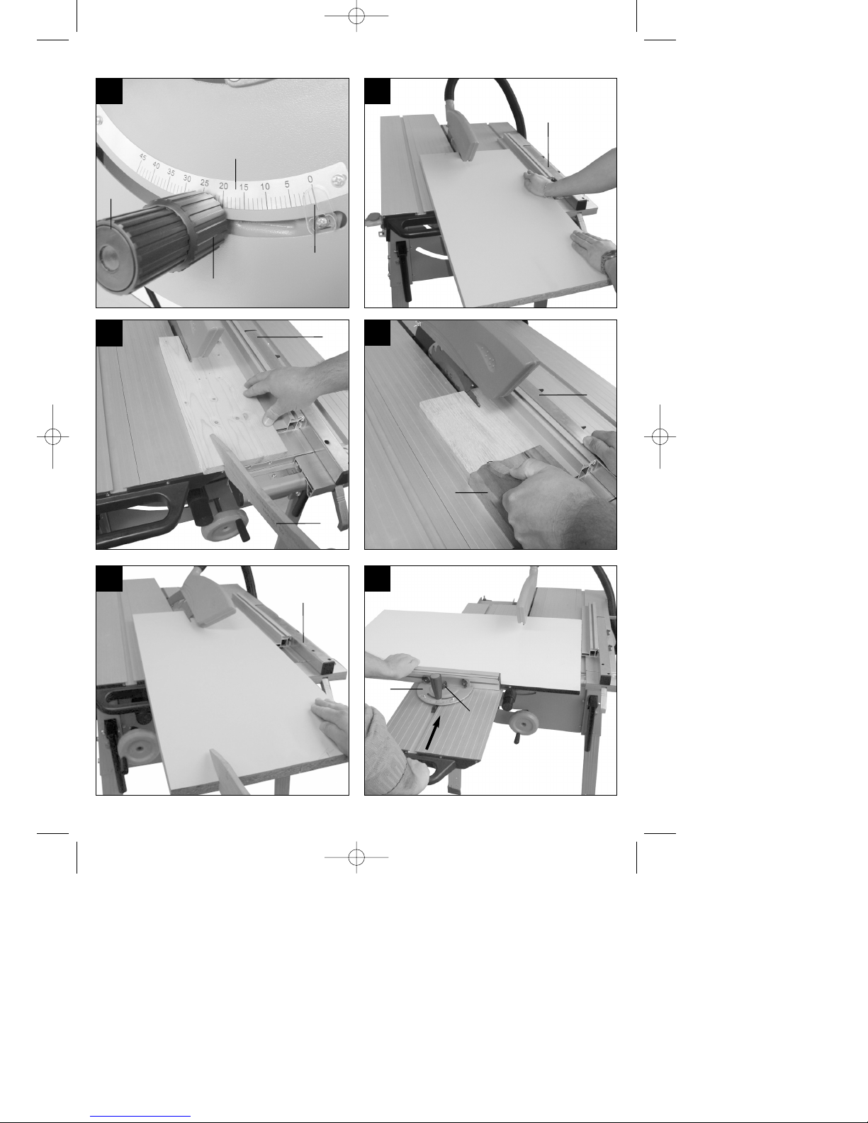
6.1.3 Einstellen der Sägeblattneigung (Bild 57)
Durch drehen des Feststellgriffes für
Sägeblattneigung (8) kann die Sägeblattneigung
eingestellt werden.
Lösen Sie die Feststellung des Griffes, durch
Linksdrehung des vorderen Griffteils (8a).
Nun können Sie durch Drehung des hinteren
Griffteils (8b) die Neigung des Sägeblatts verändern.
Der eingestellte Winkel wird durch den Zeiger (A) an
der Skala (B) angezeigt.
Arretieren Sie das Sägeblatt (12) in seiner Position,
indem Sie den vorderen Griffteil (8a) durch
Rechtsdrehung anziehen.
Achtung!
Nehmen Sie diese Einstellung nur bei
ausgeschalteter Maschine vor.
6.2 Ausführen von Längsschnitten
6.2.1 Schneiden normal großer Werkstücke
(Bild 1, 58)
Hierbei wird ein Werkstück in seiner Längsrichtung
durchschnitten. Zur Durchführung von
Längsschnitten muss der Schiebetisch (15) an der
Rückseite der Maschine mit der Tischarretierung
(siehe Punkt 5.1.3) verriegelt werden. Eine Kante
des Werkstücks wird gegen den Parallelanschlag (3)
gedrückt, während die flache Seite auf dem
Sägetisch (1) aufliegt.
Der Sägeblattschutz (18) muss immer auf dem
Werkstück aufliegen. Die Arbeitsstellung beim
Längsschnitt darf nie in einer Linie mit dem
Schnittverlauf sein.
Parallelanschlag (3) entsprechend der
Werkstückhöhe und der gewünschten Breite
einstellen. (siehe 5.3.1).
Säge einschalten (siehe 6.1.1)
Hände mit geschlossenen Fingern flach auf das
Werkstück legen und Werkstück am
Parallelanschlag (3) entlang in das Sägeblatt
(12) schieben.
Seitliche Führung mit der linken oder rechten
Hand (je nach Position des Parallelanschlages)
nur bis zu Schutzhaubenvorderkante.
Werkstück immer bis zum Ende des Spaltkeils
(17) durchschieben.
Der Schnittabfall bleibt auf dem Sägetisch (1)
liegen, bis sich das Sägeblatt (12) wieder in
Ruhestellung befindet.
6.2.2 Schneiden schmaler Werkstücke (Bild 59)
Längsschnitte von Werkstücken mit einer Breite
von weniger als 120 mm müssen unbedingt
unter Zuhilfenahme eines Schiebestockes (6)
durchgeführt werden.
Schiebestock im Lieferumfang enthalten.
Verschlissenen bzw. beschädigten Schiebestock
umgehend austauschen.
6.2.3 Schneiden sehr schmaler Werkstücke
(Bild 60)
Für Längsschnitte von sehr schmalen
Werkstücken mit einer Breite von 30 mm und
weniger ist unbedingt ein Schiebeholz (C) zu
verwenden.
Dabei ist die niedrige Führungsfläche des
Parallelanschlages zu bevorzugen.
Schiebeholz nicht im Lieferumfang enthalten!
(Erhältlich im einschlägigen Fachhandel)
Verschlissenes Schiebeholz rechtzeitig ersetzen.
6.2.4 Ausführen von Schrägschnitten (Bild 61)
Schrägschnitte werden grundsätzlich unter der
Verwendung des Parallelschlages (3) durchgeführt.
Sägeblatt (12) auf das gewünschte Winkelmaß
einstellen (siehe 6.1.3).
Parallelanschlag (3) je nach Werkstückbreite und
-höhe einstellen (siehe 5.3.1).
Schnitt entsprechend der Werkstückbreite
durchführen (siehe 6.2.1 – 6.2.3).
6.3 Arbeiten mit dem Schiebetisch
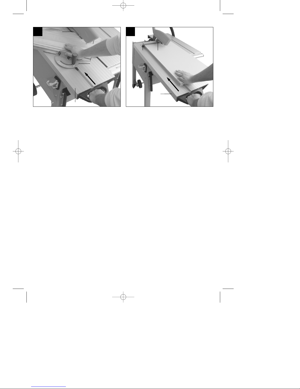
6.3.1 Ausführen von Querschnitten (Bild 62-63)
Schiebetisch (15) nach vorne ziehen.
Queranschlag (11) auf das gewünschte
Winkelmaß einstellen und auf dem Schiebetisch
(15) festklemmen (siehe 5.3.2).
Werkstück fest gegen den Queranschlag (11)
drücken und Schiebetisch (15) langsam in
Richtung Sägeblatt (12) schieben.
Schiebetisch (15) immer so weit vorschieben bis
das Werkstück vollständig durchgeschnitten ist.
Säge wieder Ausschalten. Achtung: Sägeabfall
erst entfernen, wenn das Sägeblatt (12) stillsteht.
20
D
Anleitung_RT_CC_315_UD_SPK1:_ 29.12.2008 15:33 Uhr Seite 20
Page 21

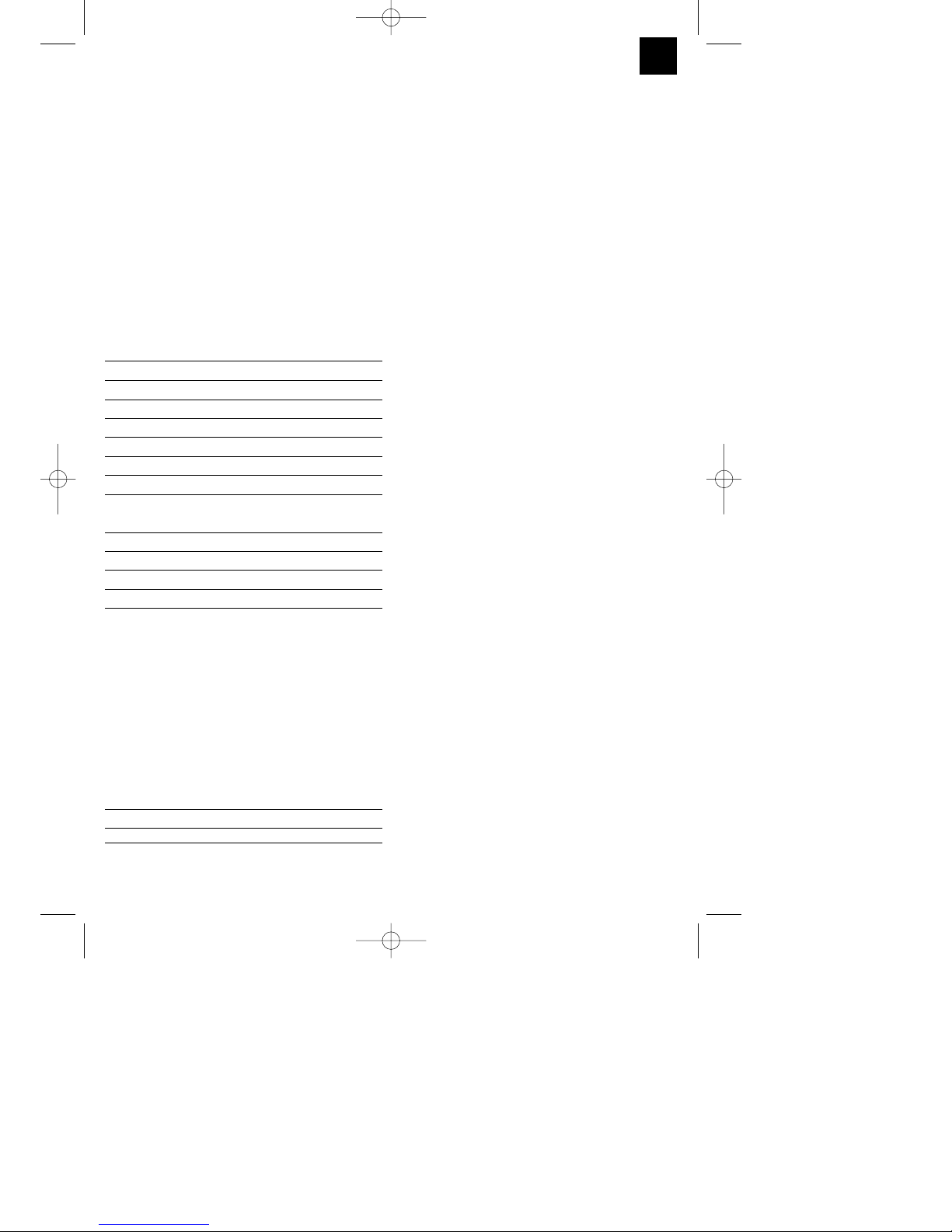
6.3.2 Besäumen mit dem Schiebetisch (Bild 64)
Beim Besäumen wird ein Brett von der Rinde und
Borke befreit und Parallel geschnitten.
Schiebetisch (15) nach vorne ziehen.
Das Werkstück auf den Schiebetisch legen und
fest gegen das Besäumungs-Hilfsblech (16)
drücken.
Den Schiebetisch (15) mit dem Werkstück dem
Sägeblatt (12) zuführen und Schnitt ausführen.
7. Reinigung, Wartung und
Ersatzteilbestellung
Ziehen Sie vor allen Reinigungsarbeiten den
Netzstecker.
7.1 Reinigung
Halten Sie Schutzvorrichtungen, Luftschlitze und
Motorengehäuse so staub- und schmutzfrei wie
möglich. Reiben Sie das Gerät mit einem
sauberen Tuch ab oder blasen Sie es mit
Druckluft bei niedrigem Druck aus.
Wir empfehlen, dass Sie das Gerät direkt nach
jeder Benutzung reinigen.
Reinigen Sie das Gerät regelmäßig mit einem
feuchten Tuch und etwas Schmierseife.
Verwenden Sie keine Reinigungs- oder
Lösungsmittel; diese könnten die Kunststoffteile
des Gerätes angreifen. Achten Sie darauf, dass
kein Wasser in das Geräteinnere gelangen kann.
7.2 Wartung
Im Geräteinneren befinden sich keine weiteren zu
wartenden Teile.
7.3 Ersatzteilbestellung:
Bei der Ersatzteilbestellung sollten folgende
Angaben gemacht werden;
Typ des Gerätes
Artikelnummer des Gerätes
Ident-Nummer des Gerätes
Ersatzteilnummer des erforderlichen Ersatzteils
Aktuelle Preise und Infos finden Sie unter
www.isc-gmbh.info
8. Entsorgung und Wiederverwertung
Das Gerät befindet sich in einer Verpackung um
Transportschäden zu verhindern. Diese Verpackung
ist Rohstoff und ist somit wieder verwendbar oder
kann dem Rohstoffkreislauf zurückgeführt werden.
Das Gerät und dessen Zubehör bestehen aus
verschiedenen Materialien, wie z.B. Metall und
Kunststoffe. Führen Sie defekte Bauteile der
Sondermüllentsorgung zu. Fragen Sie im
Fachgeschäft oder in der Gemeindeverwaltung nach!
21
D
Anleitung_RT_CC_315_UD_SPK1:_ 29.12.2008 15:33 Uhr Seite 21
Page 22

Important!
When using equipment, a few safety precautions
must be observed to avoid injuries and damage.
Please read the complete operating manual with due
care. Keep this manual in a safe place, so that the
information is available at all times. If you give the
equipment to any other person, give them these
operating instructions as well.
We accept no liability for damage or accidents which
arise due to non-observance of these instructions
and the safety information.
1. Safety information
Please refer to the booklet included in delivery for the
safety instructions.
CAUTION!
Read all safety regulations and instructions.
Any errors made in following the safety regulations
and instructions may result in an electric shock, fire
and/or serious injury.
Keep all safety regulations and instructions in a
safe place for future use.
2. Layout and items supplied /
Installation tools / Assembly
material / Supplied package
(Fig. 1-2)
2.1 Layout
1. Saw bench
2. Stop rail for parallel stop
3. Parallel stop
4. Clamp lever for parallel stop
5. Guide rail for parallel stop
6. Push stick
7. Crank handle for saw blade height
8. Fixing handle for saw blade angle
9. ON/OFF/Emergency Stop switch
10. Clamp handle for cross stop
11. Cross stop
12. Saw blade
13. Stop rail for cross stop
14. Adjustable limit stop
15. Sliding table
16. Auxiliary edging plate
17. Splitter
18. Saw blade guard
19. Extraction hose
20. Rubber legs
21. Chassis
22. Legs
23. Chip box
24. Push handles
25. Hook for tool
26. Mounting for extractor hose
27. Extractor adapter
28. Hose clips for extractor hose
2.2 Installation tools
29. Flange wrench
30. Wrench
31. Allen key
2.3 Assembly material
a 16 x Screws for legs (M10 x 20 mm)
b 16 x Washers for legs (M10)
c 16 x Spring rings for legs (M10)
d 16 x Nuts for legs (M10)
e 4 x Screws for chassis (M8 x 35 mm)
f 2 x Allen bolts for extractor hose holder (M8 x 20
mm)
g 4 x Screws for angle bracket (M8 x 20 mm)
h 14 x Washers (M8)
i 4 x Spring rings (M8)
j 8 x Nuts (M8)
k 4 x Metal brackets
l 4 x Spacers
2.4 Supplied package
Format circular saw
Parallel stop (3) with stop rail (2)
Push stick (6)
Cross stop (11)
Stop rail for cross stop (13)
Auxiliary edging plate (16)
Saw blade guard (18)
Extractor hose (19) with 2 hose clips (28)
4x Rubber feet (20)
Chassis (21)
4x Legs (22)
Mounting for extractor hose (26)
Installation tools (see point 2.2)
Assembly material (see point 2.3)
3. Proper use
The bench-type circular saw is designed for the
slitting and cross-cutting (only with the cross stop) of
timber, commensurate with the machine’s size. The
machine is not to be used for cutting any type of
round wood.
GB
22
Anleitung_RT_CC_315_UD_SPK1:_ 29.12.2008 15:33 Uhr Seite 22
Page 23

The machine is to be used only for its prescribed
purpose. Any other use is deemed to be a case of
misuse. The user / operator and not the
manufacturer will be liable for any damage or injuries
of any kind caused as a result of this.
Please note that our equipment has not been
designed for use in commercial, trade or industrial
applications. Our warranty will be voided if the
machine is used in commercial, trade or industrial
businesses or for equivalent purposes.
4. Technical data
AC motor 400V 3 ~ 50Hz
Power P 1800 W S1 2200 W S6 40%
Idle speed n
0
2750 rpm
Carbide saw blade Ø 315 x Ø 30 x 3.6 mm
Number of teeth 24
Main table dimensions 800 x 350 mm
Sliding table dimensions 1000 x 300 mm
Sliding length max. 600 mm
Cutting height max. 73 mm / 0°
49 mm / 45°
Infinite height adjustment 0 - 73 mm
Infinitely adjustable saw blade angle 0° - 45°
Dust extraction connector Ø 100 mm
Weight: 52 kg
Operating mode S1: Continuous operation
Operating mode S6 40%: Continuous operation
with idling (cycle time 10 minutes). To ensure that the
motor does not become excessively hot it may only
be operated for 40% of the cycle at the specified
rating and must then be allowed to idle for 60% of the
cycle.
Noise emission values
Operation Idle speed
LpAsound pressure level 90.6 dB 78.1 dB
LWAsound power level 105.1 dB 92.5 dB
The quoted values are emission values and not
necessarily reliable workplace values. Although there
is a correlation between emission and immission
levels it is impossible to draw any certain conclusions
as to the need for additional precautions. Factors with
a potential influence on the actual immission level at
the workplace include the duration of impact, the type
of room, and other sources of noise etc., e.g. the
number of machines and other neighboring
operations. Reliable workplace values may also vary
from country to country. With this information the user
should at least be able to make a better assessment
of the dangers and risks involved.
5. Before starting the equipment
This machine may only be assembled by trained
personnel or other personnel with similar
qualifications.
Before you connect the equipment to the mains
supply make sure that the data on the rating plate
are identical to the mains data.
Inspect the microswitch of the sliding table
regularly to ensure it works correctly. You are
allowed to operate the saw only when the sliding
table is correctly mounted.
Unpack the bench-type circular saw and check it
for damage which may have occurred in transit.
All covers and safety devices have to be properly
fitted before the machine is switched on.
It must be possible for the blade to run freely.
When working with wood that has been
processed before, watch out for foreign bodies
such as nails or screws, etc.
Before you actuate the On/Off/Emergency switch
(9), make sure that the saw blade is correctly
fitted and that the machine’s moving parts run
smoothly.
Check the supplied package to ensure it is
complete (see point 2.4).
5.1 Assembly
Important. Pull out the power plug before
carrying out any maintenance, resetting or
assembly work on the cutting-off machine!
GB
23
Anleitung_RT_CC_315_UD_SPK1:_ 29.12.2008 15:33 Uhr Seite 23
Page 24

5.1.1 Saw assembly, assembling the base frame
and chassis (Fig. 1-8)
Place the saw with the table facing down on a flat
surface.
Secure the four legs (22) from the inside to the
machine body using four screws, washers, spring
rings and nuts (a, b, c, d) in each. When you
insert the legs make sure that the lugs of the legs
fit the shape of the mounts provided (Fig. 3).
Mount the four rubber feet (20) on the legs (22).
Secure the chassis (21) on the inside to the legs
(22) using two screws, washers and nuts (e, h, j)
in each. In doing so, the 4 spacers (l) must be
inserted between the legs (22) and the angle
brackets (A) on the chassis (21). Whilst carrying
out the assembly work, ensure that the round
surfaces on the angle brackets (A) point
downwards (Fig. 4-5).
Secure the metal brackets (k) to the legs (22)
using the screws, washers, spring rings and nuts
(g, h, i, j).(Fig. 6)
Turn the saw upside down and place it on the
floor.
Secure the holder for the extractor hose (26) to
the machine body using the screws, washers and
nuts (f, h, j) and tighten the hook for the tool (25).
Attach the push stick (6) to the hook for the tool
(25) (see Fig. 7 – 8).
The machine must be stable, in other words the
saw must be secured firmly to the floor using the
metal brackets on all four legs (Fig. 6).
5.1.2 Using the chassis (Fig. 9-10/Item 21)
To extend the chassis, raise the saw slightly at
the rear (Fig. 9/1) and pull the chassis (21)
forwards (Fig. 9/2).
Then lower the saw again, keeping it in this same
position.
The saw is now standing on the wheels and can
be transported by one person with the aid of the
handles (24).(Fig 10)
Important: Never lift the saw by the sliding table.
Important: After transportation, the chassis (21)
must immediately be retracted in order to ensure
that the saw is standing securely.
To do this, return the wheels to their starting
position by following the sequence in reverse.
5.1.3 assemble / dismantle / lock the sliding table
(Fig. 11-17/Item 3)
Carefully insert the sliding table (15) in the
slideways (B) and push it forwards to the point
where the locking hook (C) latches home. (Fig. 11
- 13).
To dismantle the sliding table (15), pull the sliding
table (15) forward until the latching hook (C)
becomes visible.
Press down on the latching hook (C) with one
hand and at the same time use the other hand to
pull the sliding table (15) forward and out of the
slideway (B) (Fig. 14).
To lock the sliding table (15), slide it backward
until the lever for the table lock (D) is under the
recess on the underside of the sliding table (15)
provided for it. Push the lever to lock the table (D)
upwards and lock it by turning it clockwise (Fig.
15 – 17).
Check whether the lever for locking the table (D)
is engaged correctly and the sliding table (15) is
locked.
To release the sliding table (15), unlock the table
lock (D) by releasing the lever.
5.1.4 Fitting / removing the saw blade guard (Fig.
18/Item 18)
Mount the saw blade guard (18) on the splitter
(17) so that the screw (E) fits through the hole (F)
in the splitter (17).
Do not tighten the screw (E) too far – the saw
blade guard (18) must be able to move freely.
Important.
The saw blade guard (18) must always be
lowered over the workpiece before you begin to
cut.
5.1.5 Fitting the extractor hose (Fig. 19-21/Item
19)
Fit the extractor hose (19) to the extractor adapter
(27) and the extractor port on the saw blade
guard (18) and secure it with the hose clips for
the extractor hose (28).
Secure the extractor hose (19) to the holder for
the extractor hose (26).
A suitable extractor system has to be connected
to the outlet of the extractor adapter (27).
To dismantle, proceed in reverse order.
GB
24
Anleitung_RT_CC_315_UD_SPK1:_ 29.12.2008 15:33 Uhr Seite 24
Page 25

GB
25
5.2 Opening the chip box / Adjusting the splitter /
Replacing the saw blade (Fig. 22 – 23)
5.2.1 Opening the chip box (Fig. 22/Item 23)
Remove the saw blade guide (18) (see point
5.1.4).
Remove the sliding table (15) (see point 5.1.3).
To open the chip box (23), remove the two screws
(G) and flip open the chip box (23). Tip: You will
find it easier to remove the screws (G) if you set
an angle of approx. 30° (see 6.1.3).
To assemble, proceed in reverse order.
When closing the chip box (23) ensure that the
control pin (H) slides into the opening provided for
it on the microswitch (I).
5.2.2 Adjusting the splitter (Fig. 24-25/item 17)
Important. Pull out the power plug.
Set the saw blade (12) to maximum cutting depth
and lock it (see 6.1.2).
Open the chip box (23) (see 5.2.1).
Undo the nut (J) using the wrench (30).
Pull up the splitter (17) upwards until the gap
between the saw table (1) and the upper edge of
the splitter (17) is at its maximum (Fig. 24).
The distance between the splitter (12) and the
saw blade (17) may again be max. 8 mm (see Fig.
24 – 25).
Tighten the nut (J) again and fit the chip box (23)
again (see 5.2.1).
5.2.3 Replacing the saw blade (Fig. 26-28/item
12)
Important. Pull out the power plug. Wear
protective gloves at all times when handling
saw blades.
Set the saw blade (12) to maximum cutting depth
(see 6.1.2).
Open the chip box (23) (see point 5.2.1).
Remove the splitter (17) (see point 5.2.2).
Place the flange wrench (29) on the saw blade
flange (K).
Undo the flange screw (L) turning the wrench (30)
towards the saw blade (12) (Fig. 26).
Remove the flange screw (L) and saw blade
flange (K) (Fig. 27).
Remove the saw blade (12) from the inner flange
and pull it out in an upwards direction (Fig. 28).
Clean the saw blade flange thoroughly before
fitting the new saw blade (12).
Fit and fasten the new saw blade (12) in reverse
order.
Important. Note the running direction. The
cutting angle of the teeth must point in running
direction, i.e. forwards (see the arrow on the chip
box).
Fit and adjust the splitter (17) (see point 5.2.2).
Close the chip box (23) (see point 5.2.1).
Refit and set the saw blade guard (18) and the
sliding table (15) (see point 5.1.3 – 5.1.4)
Check to make sure that all safety devices are
properly mounted and in good working condition
before you begin working with the saw again.
5.3 Stops
5.3.1 Parallel stop
5.3.1.1 Stop height (Fig. 29 – 33)
The stop rail (2) for the parallel stop (3) has two
different guide faces (high and low).
For thick material you must use the stop rail (2) as
shown in Fig. 29, for thin material you must use
the stop rail as shown in Fig. 33.
5.3.1.2 Turning the stop rail (Fig. 31-33/Item 2)
First undo the wing nuts (B) to turn the stop rail
(2).
The stop rail (2) can now by pulled off the guide
rail (E) and can be pushed back over it with the
appropriate guide.
Retighten the wing nuts (B).
5.3.1.3 Cutting width (Fig. 29 – 30)
The parallel stop (3) has to be used when making
longitudinal cuts in wooden workpieces.
The parallel stop (3) should be mounted on the
right-hand side of the saw blade (12).
Place the parallel stop (3) on the guide rail for the
parallel stop (5) from above (Fig. 29).
There are 2 scales (C/D) on the guide rail for the
parallel stop (5) which show the distance between
the stop rail (2) and the saw blade (12) (Fig. 30).
Depending on this, choose the appropriate scale
to suit whether the stop rail (2) is turned for thick
or thin material:
High stop rail (thick material):
Scale D
Low stop rail (thin material):
Scale C
Set the parallel stop (3) for the required dimension
using the inspection window (A) and secure it
using the clamp lever for the parallel stop (4).
Anleitung_RT_CC_315_UD_SPK1:_ 29.12.2008 15:33 Uhr Seite 25
Page 26

5.3.1.4 Adjusting the stop length (Fig. 29, 34)
The stop rail (2) can be moved in longitudinal
direction in order to prevent the workpiece from
becoming jammed.
Rule of thumb: The rear end of the stop comes up
against an imaginary line that begins roughly at
the center of the blade and runs at an angle of
45° to the rear.
Set the required cutting width.
Slacken the wing nuts (B) and push the stop rail
(2) forward until it touches the imaginary 45° line.
Tighten the wing nuts (B) again.
5.3.2 Cross stop
5.3.2.1 Fitting the cross stop (Fig. 35 - 37)
Undo the clamp handle for the cross stop (10)
and wing nut (H).
Slide the cross stop (11) into the groove (F) in the
sliding table (15) (Fig. 35, 37).
Undo the wing nuts (G) and guide the stop rail for
the cross stop (13) over the screw heads on the
rear of the cross stop (11) (Fig. 36).
5.3.2.2 Stop height (Fig. 36)
The stop rail for the cross stop (13) supplied has
two different guide faces (high and low).
The stop rail must be turned to suit the thickness
of the materials you wish to cut.
Select the appropriate stop height and fit it as
described in points 5.3.1.1 and 5.3.1.2 for the
parallel stop.
5.3.2.3 Adjusting the angle of the cross stop (Fig.
37)
Undo the clamp handle for the cross stop (10)
and wing nut (H).
Turn the cross stop (11) until the pointer (I) points
to the angle required on the scale (J).
Tighten the clamp handle for the cross stop (10)
and wing nut (H) again.
5.3.2.4 Length adjustment of the parallel stop on
the sliding table (Fig. 37)
Undo the clamp handle for the cross stop (10)
and wing nut (H).
Slide the cross stop (11) into the required
position.
Tighten the clamp handle for the cross stop (10)
and wing nut (H) again.
5.3.2.5 Adjusting the stop rail for the cross stop
(Fig. 37)
Undo the wing nuts (G).
Slide the stop rail for the cross stop (13)
crossways until it reaches the required position.
Tighten the wing nuts (G) again.
Important.
Do not push the stop rail for the cross stop (13)
too far toward the saw blade (12).
The distance between the stop rail for the cross
stop (13) and the saw blade (12) should be
approx. 2 cm.
5.3.3 Sliding limit stop (Fig. 38-39)
To simplify cutting several workpieces of equal
length, the stop rail for the cross stop (13) is fitted
with an adjustable limit stop (14).
Undo the wing nut (K), slide the adjustable limit
stop (14) into the required position on the stop rail
for the cross stop (13) and then retighten the wing
nut (K).
The adjustable limit stop (14) can be moved away
upwards so that, for example, the edges of the
workpiece can be cut straight first, then the
workpiece can be turned and cut to the required
length with the limit stop (14) extended
downwards.
The adjustable limit stop (14) can be removed
from the stop rail for the cross stop (13) by
undoing the wing nut (K) and removing the
adjustable limit stop (14) from the stop rail for the
cross rail (13).
To assemble, proceed in reverse order.
5.3.4 Auxiliary edging plate (Fig. 40-43)
The auxiliary edging plate (16) is used as a limit
stop for edging.
Fit the auxiliary edging plate (16) to the sliding
table (15) as shown in Fig. 40 – 43).
Ensure that the metal plate (N) and the guide lug
(M) are in the groove (F) in the sliding table (15).
Slide the auxiliary edging plate (16) into the
required position and secure it by tightening the
wing nut (L).
5.4 Adjusting the saw
Important. This saw is a precision tool which may
need to be readjusted after it is assembled or put in
position. Please carry out adjustments as described
in the following instructions:
26
GB
Anleitung_RT_CC_315_UD_SPK1:_ 29.12.2008 15:33 Uhr Seite 26
Page 27

5.4.1. Adjusting the saw blade (Figure 44-45)
Use the stop angle (a) and the locking grip for the saw
blade angle (8) to adjust the saw blade (12) so that it
makes an angle of 90° relative to the saw table (1).
Check whether the pointer (b) stands at 0°. If not,
undo the two screws (c) and adjust the scale (d) so
that the pointer (b) stands at 0°. Then refasten the
scale (d) with the two screws. Small deviations can
also be corrected by slackening the screw (e) and
adjusting the pointer (b).
5.4.2. Adjusting the parallel stop (Figure 46-47)
Move the parallel stop (3) to the left until the stop rail
for the parallel stop (2) touches the saw blade (12),
then secure it in place with the clamp lever for the
parallel stop (4). Check whether the stop rail for the
parallel stop (2) is parallel with the saw blade (12). If
not, undo the two Allen screws (f) and align the
parallel stop (3) so that the stop rail for the parallel
stop (2) runs parallel to the saw blade (12). Then
refasten the parallel stop (3) with the two Allen
screws.(f)
5.4.3. Adjusting the cross stop (Figure 47-48)
Undo the locking grip for the cross stop (10) and align
the stop rail for the cross stop (13) using the stop
angle (A) as shown in Fig. 47 so that it makes an
angle of 90° relative to the parallel stop (2). Check
whether the pointer (i) stands at 0°. If not, undo the
two screws (g) and adjust the scale (j) so that the
pointer (i) stands at 0°. Then refasten the scale (j)
with the two screws (g).
5.4.4. Adjusting the sliding table (Figure 48-53)
Check whether the sliding table (15) is level with saw
table (1), as shown in Figure 51. If not, undo the two
screws (o) and (p) on the front and rear sides and
align the sliding table (15) so that it is level with the
saw table (1).
Then secure the sliding table (15) with the four
screws (o and p). The saw table (1) has two ball
bearings (k/m) which help the table to slide. Check on
the front and rear sides of the saw whether the ball
bearings touch the guide rail (q). If not, undo the
screws (l) and (n) and align the ball bearings (k/m) so
that they touch the guide rail (q). Then refasten the
ball bearings (k/m) with the two screws (l/n).
6. Operation
Important!!
After every new adjustment we recommend you
to make a trial cut in order to check the new
settings.
After switching on the saw, wait for the blade to
reach its maximum speed of rotation before
commencing with the cut.
Take extra care when starting the cut!
6.1 Control elements
6.1.1 ON/OFF/Emergency Stop switch (Fig. 54-55
/ Item 9)
Pull the cover on the ON/OFF/Emergency Stop
switch (9) upwards.
To turn the saw on, press the green button “1”.
To turn the machine off again, press the red
button “0”.
Important.
The saw has an emergency stop function. Press the
cover on the ON/OFF/Emergency Stop switch (Fig.
54/Item 9) to switch off the machine quickly and
easily.
6.1.2 Setting the cutting depth (Fig. 56)
Turn the crank handle for the saw blade height (7)
to set the saw blade (12) to the required cutting
depth.
Turn the crank handle for the saw blade height (9):
Turn anti-clockwise: larger cutting depth
Turn clockwise: smaller cutting depth
Important.
Only make this adjustment after the machine has
been switched off.
6.1.3 Setting the saw blade angle (Fig. 57)
The saw blade angle can be adjusted by turning the
locking grip for the saw blade angle (8).
Undo the grip lock by turning the front grip part (8a)
anti-clockwise. The angle of the saw blade can now
be changed by turning the rear grip part (8b). The set
angle is shown by the pointer (A) on the scale (B).
Lock the saw blade (12) in position by tightening the
front grip part (8a) by turning it clockwise.
Important.
Only make this adjustment after the machine has
been switched off.
27
GB
Anleitung_RT_CC_315_UD_SPK1:_ 29.12.2008 15:33 Uhr Seite 27
Page 28

6.2 Completing longitudinal cuts
6.2.1 Cutting workpieces of normal size (Fig. 1,
58)
Longitudinal cutting (also known as slitting) is when
you use the saw to cut along the grain of the wood.
To complete longitudinal cuts the sliding table (15)
must be locked to the rear of the machine using the
table lock (see point 5.1.3). Press one edge of the
workpiece against the parallel stop (3) while the flat
side lies on the saw table (1).
The saw blade guard (18) must always lie on the
workpiece. When you make a longitudinal cut, never
adopt a working position that is in line with the cutting
direction.
Set the parallel stop (3) in accordance with the
workpiece height and the desired width. (see
5.3.1).
Switch on the saw (see 6.1.1).
Place your hands (with fingers closed) flat on the
workpiece and push the workpiece along the
parallel stop (3) and into the blade (12).
Guide at the side with your left or right hand
(depending on the position of the parallel stop)
only as far as the front edge of the guard hood.
Always push the workpiece through to the end of
the splitter (17).
The offcut piece remains on the saw table (1) until
the blade (12) is back in its position of rest.
6.2.2 Cutting narrow workpieces (Fig. 59)
Be sure to use a push stick (6) when making
longitudinal cuts in workpieces smaller than 120
mm in width.
A push stick is supplied with the saw.
Replace a worn or damaged push stick
immediately.
6.2.3 Cutting very narrow workpieces (Fig. 60)
Be sure to use a push block (C) when making
longitudinal cuts in very narrow workpieces with a
width of 1.18 in and less.
The low guide face of the parallel stop is best
used in this case.
There is no push block supplied with the saw!
(Available from your specialist dealer)
Replace the push block without delay when it
becomes worn.
6.2.4 Completing angular cuts (Fig. 61)
Angular cuts must always be used using the parallel
stop (3).
Set the blade (12) to the desired angle (see
6.1.3).
Set the parallel stop (3) in accordance with the
workpiece width and height (see 5.3.1).
Carry out the cut in accordance with the
workpiece width (see 6.2.1 – 6.2.3).
6.3 Working with the sliding table
6.3.1 Completing cross cuts (Fig. 62-63)
Pull the sliding table (15) forward.
Set the cross stop (11) to the required angle
dimension and clamp it in place on the sliding
table (15) (see 5.3.2).
Press the workpiece firmly against the cross stop
(11) and push the sliding table (15) slowly toward
the blade (12).
Always push the sliding table (15) forward to the
point where the workpiece is cut all the way
through.
Switch off the saw again. Important: Do not
remove the offcut until the blade (12) has stopped
rotating.
6.3.2 Making edging cuts with the sliding table
(Fig. 64)
The edging process removes the inner and outer bark
from a board and cuts it parallel.
Pull the sliding table (15) forward.
Place the workpiece on the sliding table and
press it firmly against the auxiliary edging plate
(16)
Push the sliding table (15) with the workpiece
toward the blade (12) and make the cut.
7. Cleaning, maintenance and ordering
of spare parts
Always pull out the mains power plug before starting
any cleaning work.
7.1 Cleaning
Keep all safety devices, air vents and the motor
housing free of dirt and dust as far as possible.
Wipe the equipment with a clean cloth or blow it
with compressed air at low pressure.
We recommend that you clean the device
immediately each time you have finished using it.
Clean the equipment regularly with a moist cloth
and some soft soap. Do not use cleaning agents
or solvents; these could attack the plastic parts
28
GB
Anleitung_RT_CC_315_UD_SPK1:_ 29.12.2008 15:33 Uhr Seite 28
Page 29
of the equipment. Ensure that no water can seep
into the device.
7.2 Maintenance
There are no parts inside the equipment which
require additional maintenance.
7.3 Ordering replacement parts
Please quote the following data when ordering
replacement parts:
Type of machine
Article number of the machine
Identification number of the machine
Replacement part number of the part required
For our latest prices and information please go to
www.isc-gmbh.info
8. Disposal and recycling
The unit is supplied in packaging to prevent its being
damaged in transit. This packaging is raw material
and can therefore be reused or can be returned to
the raw material system.
The unit and its accessories are made of various
types of material, such as metal and plastic.
Defective components must be disposed of as
special waste. Ask your dealer or your local council.
29
GB
Anleitung_RT_CC_315_UD_SPK1:_ 29.12.2008 15:33 Uhr Seite 29
Page 30

Attention !
Lors de l’utilisation d’appareils, il faut respecter
certaines mesures de sécurité afin d’éviter des
blessures et dommages. Veuillez donc lire
attentivement ce mode d’emploi. Conservez-le bien
de façon à pouvoir disposer à tout moment de ces
informations. Si l’appareil doit être remis à d’autres
personnes, remettez-leur aussi ce mode d’emploi.
Nous déclinons toute responsabilité pour les
accidents et dommages dus au non-respect de ce
mode d’emploi et des consignes de sécurité.
1. Consignes de sécurité
Vous trouverez les consignes de sécurité
correspondantes dans le petit manuel ci-joint.
AVERTISSEMENT !
Veuillez lire toutes les consignes de sécurité et
instructions.
Tout non-respect des consignes de sécurité et
instructions peut provoquer une décharge électrique,
un incendie et/ou des blessures graves.
Conservez toutes les consignes de sécurité et
instructions pour une consultation ultérieure.
2. Description de l’appareil / Outil de
montage / Matériel de montage /
Volume de livraison (figure 1-2)
2.1 Description de l’appareil
1. Table de sciage
2. Rail de butée pour butée parallèle
3. Butée parallèle
4. Levier de serrage pour butée parallèle
5. Rail de guidage pour butée parallèle
6. Poussoir
7. Manivelle pour hauteur de lame
8. Poignée de blocage pour inclinaison de lame
9. Interrupteur marche/arrêt/arrêt d’urgence
10. Poignée de serrage pour butée transversale
11. Butée transversale
12. Lame de scie
13. Rail de butée pour butée transversale
14. Butée fin de course mobile
15. Table coulissante
16. Tôle d’aide au rognage
17. Coin à refendre
18. Capot de protection de lame de scie
19. Tuyau flexible d’aspiration
20. Pieds en caoutchouc
21. Châssis
22. Pieds d’appui
23. Bac à copeaux
24. Poignées de déplacement
25. Crochet pour outil
26. Support pour tuyau d’aspiration
27. Adaptateur d’aspiration
28. Colliers de serrage pour tuyau d’aspiration
2.2 Outil de montage
29. Clé à bride
30. Clé à vis
31. Clé à six pans creux
2.3 Matériel de montage
a 16 x vis pour pieds d’appui (M10 x 20mm)
b 16 x rondelles pour pieds d’appui (M10)
c 16 x circlips pour pieds d’appui (M10)
d 16 x écrou pour pieds d’appui (M10)
e 4 x vis pour châssis (M8 x 35mm)
f 2 x boulon à six pans creux pour support tuyau
d’aspiration (M8 x 20mm)
g 4 x vis pour équerre de fixation (M8 x 20mm)
h 14 x rondelles (M8)
i 4 x circlip (M8)
j 8 x écrou (M8)
k 4 x équerre métallique
l 4 x pièce d’écartement
2.4 Volume de livraison
Scie circulaire à format
Butée parallèle (3) avec rail de butée (2)
Poussoir (6)
Butée transversale (11)
Rail de butée pour butée transversale (13)
Tôle d’aide au rognage (16)
Capot de protection de lame de scie (18)
Tuyau d’aspiration (19) avec 2 colliers de serrage
(28)
4 x pieds en caoutchouc (20)
Châssis (21)
4 x pieds d’appui (22)
Support pour tuyau d’aspiration (26)
Outil de montage (voir point 2.2)
Matériel de montage (cf. point 2.3)
3. Utilisation conforme à l’affectation
La scie circulaire à table sert à scier en longueur et
transversalement (uniquement avec butée
transversale) des bois de tous genres en fonction de
la taille de la machine. Les bois ronds de tous genres
ne doivent pas être découpés.
F
30
Anleitung_RT_CC_315_UD_SPK1:_ 29.12.2008 15:33 Uhr Seite 30
Page 31

La machine doit exclusivement être employée
conformément à son affectation. Chaque utilisation
allant au-delà de cette affectation est considérée
comme non conforme. Pour les dommages en
résultant ou les blessures de tout genre, le
producteur décline toute responsabilité et
l’opérateur/l’exploitant est responsable.
Veillez au fait que nos appareils, conformément à
leur affectation, n’ont pas été construits, pour être
utilisés dans un environnement professionnel,
industriel ou artisanal. Nous déclinons toute
responsabilité si l’appareil est utilisé
professionnellement, artisanalement ou dans des
sociétés industrielles, tout comme pour toute activité
équivalente.
4. Données techniques
Moteur à courant alternatif 400V 3 ~ 50 Hz
Puissance P 1800 W S1 2200 W S6 40%
Vitesse de rotation de marche à vide n02750 tr/min
Lame de scie en métal dur ø 315 x ø 30 x 3,6 mm
Nombre de dents 24
Grande table principale 800 x 350 mm
Grande table coulissante 1000 x 300 mm
Longueur de décalage maxi. 600 mm
Hauteur de coupe max. 73 mm / 0°
49 mm / 45°
Réglage en hauteur en continu 0 - 73 mm
Lame de scie pivotante en continu 0° - 45°
Raccord d’aspiration Ø 100 mm
Poids : 52 kg
Mode d’exploitation S1 : fonctionnement continu
Mode d’exploitation S6 40% : marche continue
avec service discontinu (temps de marche 10 mn).
Afin de ne pas faire chauffer le moteur de façon
inadmissible, il faut le faire fonctionner pendant 40%
du temps de marche à la puissance nominale et
ensuite 60% du temps de marche sans charge.
Valeurs d’émission de bruit
Service à vide
Niveau de pression acoustique LpA90,6 dB 78,1 dB
Niveau de puissance acoustique LWA105,1 dB 92,5 dB
Les valeurs indiquées sont des valeurs d’émission et
ne doivent donc pas représenter simultanément aussi
des valeurs de poste de travail sûres. Bien qu’il y ait
une corrélation entre le niveau d’émission et celui
d’immission, on ne peut déduire avec certitude si des
mesures de précaution supplémentaires sont
nécessaires ou non. Les facteurs pouvant influencer
le niveau d’immission présent sur le moment au poste
de travail comprennent la durée des effets, la sorte
de salle de travail, les autres sources de bruit, etc.
par ex. le nombre de machines et autres processus
voisins. Les valeurs de poste de travail fiables
peuvent aussi varier d’un pays à l’autre. Cette
information est cependant destinée à rendre les
personnes utilisant l’outil capables de mieux estimer
les risques et dangers.
5. Avant la mise en service
Cet appareil doit uniquement être monté par un
spécialiste ou une autre personne qualifiée de la
même manière.
Assurez-vous, avant de connecter la machine,
que les données se trouvant sur la plaque de
signalisation correspondent bien aux données du
réseau.
Contrôlez régulièrement si le microrupteur de la
table coulissante fonctionne correctement ! La
scie doit uniquement être utilisée lorsque la table
coulissante est correctement montée.
Déballez la scie circulaire à table et contrôlez si
elle n’a pas été éventuellement endommagée par
le transport.
Avant la mise en service, les recouvrements et
dispositifs de sécurité doivent être montés dans
les règles de l’art.
La lame de scie doit pouvoir tourner sans
obstacle.
Dans le cas de bois ayant déjà été traité, veillez
aux corps étrangers, comme par ex. les clous ou
vis, etc.
Avant d’actionner l’interrupteur marche/arrêt/arrêt
d’urgence (9), assurez-vous que la lame de scie
est correctement montée et que les pièces
amovibles le sont sans obstacle.
Vérifiez l’intégralité de la livraison (voir point 2.4).
F
31
Anleitung_RT_CC_315_UD_SPK1:_ 29.12.2008 15:33 Uhr Seite 31
Page 32

5.1 Montage
Attention ! Retirez la fiche secteur avant tout
travail de maintenance, de changement
d’équipement et de montage de la scie circulaire.
5.1.1 Monter la scie, installer le support et le
châssis (fig. 1-8)
Mettez la scie avec la table vers le bas sur un
support plan.
Vissez les quatre pieds d’appui (22) à l’aide de
quatre vis, rondelles, circlips et écrous (a, b, c, d)
de l’intérieur au bâti de la machine. Attention en
enfichant les pieds d’appui à ce que les
languettes des pieds d’appui conviennent à la
forme des logements prévus à cet effet (figure 3).
Emmanchez les quatre pieds en caoutchouc (20)
sur les pieds d’appui (22).
Vissez le châssis (21) avec 2 vis, rondelles et
écrous (e, h, j) à l’intérieur aux pieds d’appui (22).
Ce faisant, il faut insérer les 4 pièces
d’écartement (l) entre les pieds d’appui (22) et les
équerres de fixation (A) du châssis (21). Veillez
lors du montage à ce que les arrondis de
l’équerre de fixation (A) pointent vers le bas. (fig.
4-5)
Vissez à fond les équerres métalliques (k) avec
les vis, les rondelles, les circlips et les écrous (g,
h, i, j) au niveau des pieds d’appui (22) (figure 6).
Retournez la scie et placez-la au sol.
Vissez à fond le support pour tuyau d’aspiration
(26) à l’aide des vis, rondelles et écrous (f, h, j) au
bâti de la machine et serrez le crochet pour outil
(25). Accrochez le poussoir (6) sur le crochet
pour outil (25) (voir figure 7 - 8)
La machine doit être placée de façon stable,
autrement dit, la scie doit être vissée à fond avec
les équerres métalliques, qui se trouvent aux
quatre pieds d’appui (figure 6).
5.1.2 Utiliser le châssis (fig. 9-10/pos. 21)
Pour ouvrir le châssis, soulevez légèrement la
scie au dos (figure 9/1.) et tirez le châssis (21)
vers l’avant (figure 9/2.).
Rabaissez la scie circulaire à table dans cette
position.
A présent, la scie circulaire à table est sur les
roues et peut être transportée par une personne à
l’aide des poignées de déplacement (24) (figure
10).
Attention : ne soulevez jamais la scie sur la table
coulissante !
Attention : après le transport, le châssis (21) doit
être tout de suite à nouveau rabattu afin de
garantir une position stable de la scie.
Pour ce faire, remettez tout dans la position de
départ, en procédant dans l’ordre inverse.
5.1.3 Monter / démonter / bloquer la table
coulissante (fig. 11-17/pos. 3)
Introduisez précautionneusement la table
coulissante (15) dans les guidages à glissement
(B), poussez-les en avant jusqu’à ce que le
crochet de verrouillage (C) s’enclenche (figures
11 - 13).
Pour démonter la table coulissante (15), tirez la
table coulissante (15) en avant jusqu’à ce que le
crochet de verrouillage (C) soit visible.
Poussez le crochet de verrouillage (C) d’en haut
d’une main et tirez simultanément de l’autre la
table coulissante (15) en avant hors du guidage
(B) (figure 14) !
Pour bloquer la table coulissante (15), poussez-la
en arrière jusqu’à ce que le levier pour blocage
de la table (D) se trouve sous l’encoche prévue à
cet effet au niveau de la face inférieure de la table
coulissante (15). Poussez le levier pour blocage
de la table (D) vers le haut et bloquez-le par
rotation à droite (figure 15 – 17).
Contrôlez si le levier pour blocage de la table (D)
s’enclenche correctement et que la table
coulissante (15) est bloquée.
Pour détacher la table coulissante (15),
déverrouillez le blocage de la table (D) en
desserrant le levier.
5.1.4 Monter / démonter le capot de protection
de lame de scie (figure 18/pos. 18)
Mettez le capot de protection de lame de scie
(18) sur le coin à refendre (17), de façon que la
vis (E) aille à travers le trou (F) du coin à refendre
(17).
Ne vissez pas la vis (E) à fond ; le capot de
protection de la lame (18) doit pouvoir bouger
librement.
Attention !
Le capot de protection de lame (18) doit être
baissé sur l’objet à scier avant de commencer le
sciage.
5.1.5 Monter le tuyau d’aspiration (figures 1921/pos. 19)
Enfichez le tuyau d’aspiration (19) sur
l’adaptateur d’aspiration (27) et la tubulure
d’aspiration du capot de protection de lame de
scie (18) et bloquez-le avec les colliers de
serrage pour tuyau d’aspiration (28).
Fixez le tuyau d’aspiration (19) au support pour
tuyau d’aspiration (26).
Il faut raccorder un système d’aspiration adéquat
à la sortie de l’adaptateur d’aspiration (27).
Le démontage doit être effectué dans l’ordre
inverse.
F
32
Anleitung_RT_CC_315_UD_SPK1:_ 29.12.2008 15:33 Uhr Seite 32
Page 33

F
33
5.2 Ouvrir la caisse à copeaux / Régler le coin à
refendre / Changer la lame de scie (figures
22-23)
5.2.1 Ouvrir la caisse à copeaux (figure 22/pos.
23)
Démontez le capot de protection de lame de scie
(18) (voir point 5.1.4).
Démontez la table coulissante (15) (voir point
5.1.3).
Pour ouvrir la caisse à copeaux (23), retirez les
deux vis (G) et ouvrez la caisse à copeaux (23).
Astuce : réglez un angle d’env. 30° pour retirer les
vis (G) plus facilement (voir 6.1.3).
Le montage se fait dans l’ordre inverse.
Veillez lors de la fermeture de la caisse à
copeaux (23) à ce que la cheville de commutation
(H) glisse dans l’ouverture prévue à cet effet au
niveau du microrupteur (I).
5.2.2 Régler le coin à refendre (figures 24-25/pos.
17)
Attention ! Tirez la fiche de contact
Réglez la lame de scie (12) sur la profondeur de
coupe maximum et bloquez-la (cf. 6.1.2)
Ouvrez la caisse à copeaux (23) (voir 5.2.1).
Desserrez l’écrou (J) avec la clé à vis (30).
Tirez le coin à refendre (17) vers le haut jusqu’à
ce que l’écart entre la table de sciage (1) et le
bord supérieur du coin à refendre (17) soit au
maximum (figure 24).
L’espace entre la lame de scie (12) et le coin à
refendre (17) doit être de 8 mm au maximum
(figures 24-25).
Resserrez à fond l’écrou (J) et remontez la caisse
à copeaux (23) (voir 5.2.1).
5.2.3 Changer de lame de scie (figures 26-28/pos.
12)
Attention ! Retirez la fiche de contact. Portez
toujours des gants de protection lorsque
vous manipulez les lames de scie.
Réglez la lame de scie (12) sur la profondeur de
coupe maximum (cf. 6.1.2).
Ouvrez la caisse à copeaux (23) (voir 5.2.1).
Démontez le coin à refendre (17) (voir point
5.2.2).
Placez la clé à bride (29) sur la bride de la lame
de scie (K).
Dévissez la vis à bride (L) avec la clé à vis (30)
dans le sens du mouvement de la lame de scie
(12) (figure 26).
Retirez la vis à bride (L) et la bride de la lame de
scie (K) (figure 27).
Retirez la lame de scie (12) de la bride intérieure
et la sortir d’en haut (figure 28).
Avant le montage de la nouvelle lame de scie
(12), les brides de lame de scie doivent être
consciencieusement nettoyées.
Placez la nouvelle lame de scie (12) en procédant
dans l’ordre inverse et serrez à fond.
Attention ! Respectez le sens de la course, le
biais de coupe des dents doit pointer dans le
sens du mouvement, c.à.d. vers l’avant (cf. flèche
sur la caisse à copeaux).
Remontez et réglez le coin à refendre (17) (voir
point 5.2.2).
Fermez la caisse à copeaux (23) (voir point
5.2.1).
Remontez le capot de protection de lame de scie
(18) et la table coulissante (15) et réglez-la (voir
point 5.1.3-5.1.4).
Avant de travailler à nouveau avec la scie, il faut
contrôler le bon fonctionnement des dispositifs de
protection.
5.3 Butées
5.3.1 Butée parallèle
5.3.1.1 Hauteur de butée (figures 29 – 33)
Le rail de butée (2) de la butée parallèle (3)
dispose de deux surfaces de guidage de hauteur
différente.
En fonction de l’épaisseur des matériaux à
découper, le rail de butée (2) devant être employé
est celui destiné au matériau épais comme en fig.
29 ou au matériau mince comme en fig. 33.
5.3.1.2 Tourner le rail de butée (figures 3133/pos. 2)
Desserrez les écrous à oreilles (B) pour tourner le
rail de butée (2).
Le rail de butée (2) peut être retiré maintenant du
rail de guidage (E) et être repoussé au-dessus de
celui-ci avec le guidage correspondant.
Resserrez les écrous à oreilles (B).
5.3.1.3 Largeur de coupe (figures 29 - 30)
Il faut utiliser la butée parallèle (3) pour découper
des pièces de bois dans le sens de la longueur.
La butée parallèle (3) doit être montée sur le côté
droit de la lame de scie (12).
Placez la butée parallèle (3) d’en haut sur le rail
de guidage pour butée parallèle (5) (figure 29).
Le rail de guidage pour butée parallèle (5)
comporte 2 échelles (C/D) qui indiquent l’écart
entre le rail de butée (2) et la lame de scie (12)
(figure 30).
Anleitung_RT_CC_315_UD_SPK1:_ 29.12.2008 15:33 Uhr Seite 33
Page 34

Sélectionnez l’échelle appropriée selon si le rail
de butée (2) est tourné pour l’usinage de
matériau épais ou fin :
Rail de butée haut (matériau épais) :
Echelle D
Rail de butée bas (matériau fin) :
Echelle C
Ajustez la butée parallèle (3) sur la cote
souhaitée au niveau du verre-regard (A) et fixezla avec le levier de serrage pour butée parallèle
(4).
5.3.1.4 Régler la longueur de butée (figures 29,
34)
Pour éviter le blocage de l’objet à couper, il faut
glisser le rail de butée (2) en longueur.
Règle générale : l’extrémité arrière de la butée
bute contre une ligne imaginaire qui commence à
peu près au milieu de la lame de scie et s’étend
vers l’arrière à 45°.
Réglez la largeur de coupe nécessaire.
Desserrez les écrous à oreilles (B) et avancez le
rail de butée (2) jusqu’à ce qu’il touche la ligne
imaginaire de 45°.
Serrez à nouveau à fond les écrous à oreilles (B).
5.3.2 Butée transversale
5.3.2.1 Montage de la butée transversale (figures
35 - 37)
Desserrez la poignée de serrage pour butée
transversale (10) et l’écrou à oreilles (H).
Poussez la butée transversale (11) dans la
rainure (F) de la table coulissante (15) (figures
35, 37).
Desserrez les écrous à oreilles (G) et amenez le
rail de butée pour butée transversale (13) audessus des têtes de vis au dos de la butée
transversale (11) (figure 36).
5.3.2.2 Hauteur de butée (figure 36)
Le rail de butée pour butée transversale (13)
dispose de deux surfaces de guidage de
différentes hauteurs.
Il faut tourner le rail de butée en fonction de
l’épaisseur des matériaux à couper.
Sélectionnez la hauteur de butée correspondante
et montez-la comme décrit aux points 5.3.1.1 ou.
5.3.1.2 pour la butée parallèle.
5.3.2.3 Réglage d’angle de la butée transversale
(figure 37)
Desserrez la poignée de serrage pour butée
transversale (10) et l’écrou à oreilles (H).
Tournez la butée transversale (11) jusqu’à ce que
l’aiguille (I) pointe sur la cote d’angle souhaitée
au niveau de l’échelle (J).
Resserrez la poignée de serrage pour butée
transversale (10) et l’écrou à oreilles (H).
5.3.2.4 Réglage de la longueur de la butée
parallèle sur la table coulissante (figure
37)
Desserrez la poignée de serrage pour butée
transversale (10) et l’écrou à oreilles (H).
Poussez la butée transversale (11) dans la
position désirée.
Resserrez la poignée de serrage pour butée
transversale (10) et l’écrou à oreilles (H).
5.3.2.5 Réglage du rail de butée pour butée
transversale (figure 37)
Desserrez les écrous à oreilles (G).
Déplacez le rail de butée pour butée transversale
(13) transversalement jusqu’à ce que la position
désirée soit atteinte.
Resserrez les écrous à oreilles (G).
Attention !
Ne poussez pas trop le rail de butée pour butée
transversale (13) en direction de la lame de scie
(12).
L’écart entre le rail de butée pour butée
transversale (13) et la lame de scie (12) doit
s’élever à env. 2 cm.
5.3.3 Butée fin de course mobile (figures 38-39)
Afin de simplifier la mise à longueur de plusieurs
pièces à usiner de même longueur, le rail de
butée pour butée transversale (13) est équipé
d’une butée fin de course (14) mobile.
Desserrez l’écrou à oreilles (K), poussez la butée
fin de course mobile (14) dans la position désirée
sur le rail de butée pour butée transversale (13) et
serrez à nouveau l’écrou à oreilles (K).
La butée fin de course mobile (14) peut être
rabattue vers le haut, pour p. ex. commencer à
couper droit les arêtes de la pièce à usiner,
tourner la pièce à usiner puis couper avec la
butée fin de course (14) rabattue à la longueur
adaptée.
La butée fin de course mobile (14) peut être
retirée du rail de butée pour butée transversale
(13) en desserrant l’écrou à oreilles (K) et en
enlevant la butée fin de course mobile du rail de
butée pour butée transversale (13).
Le montage se fait dans l’ordre inverse.
34
F
Anleitung_RT_CC_315_UD_SPK1:_ 29.12.2008 15:33 Uhr Seite 34
Page 35

5.3.4 Tôle d’aide au rognage (figure 40-43)
La tôle d’aide au rognage (16) sert de butée fin
de course lors du rognage.
Montez la tôle d’aide au rognage (16)
conformément aux illustrations 40 – 43 sur la
table coulissante (15).
Veillez à ce que les plaquettes métalliques (N) et
le crochet de guidage (M) sont dans la rainure (F)
de la table coulissante (15).
Poussez la tôle d’aide au rognage (16) dans la
position désirée et fixez-la en serrant l’écrou à
oreilles (L).
5.4 Ajustement de la scie
Attention ! Comme cette scie est un outil de
précision, il est nécessaire de la rajuster après son
montage ou sa mise en place. Pour ce faire,
procédez selon les instructions suivantes.
5.4.1. Ajustement de la lame de la scie (figures
44-45)
Dirigez la lame de scie (12) à l’aide de l’équerre de
butée (a) et la poignée de blocage pour inclinaison de
lame (8) de manière à former un angle de 90° par
rapport à la table de sciage (1). Contrôlez si l’aiguille
(b) pointe bien sur 0°. Si tel n’est pas le cas,
desserrez les deux vis (c) et ajustez l’échelle graduée
(d) de manière que l’aiguille (b) pointe sur 0°. Refixez
ensuite l’échelle graduée (d) avec les deux vis. Il est
possible de corriger également des petites
irrégularités en desserrant la vis (e) et en réglant
l’aiguille (b).
5.4.2. Ajustement de la butée parallèle (figures
46-47)
Poussez la butée parallèle (3) vers la gauche, jusqu’à
ce que le rail de butée pour butée parallèle (2) touche
la lame de scie (12) et bloquez-la ensuite avec le
levier de serrage pour butée parallèle (4). Vérifiez si
le rail de butée pour butée parallèle (2) est parallèle à
la lame de scie (12). Sinon, desserrez les deux vis à
six pans creux (f) et dirigez la butée parallèle (3) de
manière que le rail de butée pour butée parallèle (2)
s’étendent parallèlement à la lame de scie (12). Fixez
ensuite à nouveau la butée parallèle (3) avec les
deux boulons à six pans creux (f).
5.4.3. Ajustement de la butée transversale
(figures 47-48)
Desserrez la poignée de serrage pour butée
transversale (10) et ajustez le rail de butée pour butée
transversale (13) à l’aide de l’équerre de butée (A),
comme sur la figure 47, à un angle de 90° par rapport
au rail de butée pour butée parallèle (2). Contrôlez si
l’aiguille (i) pointe bien sur 0°. Si tel n’est pas le cas,
desserrez les deux vis (g) et ajustez l’échelle graduée
(j) de manière que l’aiguille (i) pointe sur 0°. Refixez
ensuite l’échelle (j) graduée avec les deux vis (g).
5.4.4. Ajustement de la table coulissante (figures
48-53)
Contrôlez, comme indiqué en figure 51, si la table
coulissante (15) est bien plane par rapport à la table
de sciage (1). Si tel n’est pas le cas, desserrez les
deux vis (o) ou (p) à l’avant et au dos et redressez la
table coulissante (15) de façon à ce qu’elle soit plane
par rapport à la table de menuisier (1).
Ensuite fixez à nouveau la table coulissante (15) avec
les quatre vis (o ou p). La table de menuisier (1) a
deux roulements à billes (k/m) qui aident à faire
glisser la table. Contrôlez à l’avant comme au dos de
la scie, si les roulements à billes touchent le rail de
guidage (q). Sinon, desserrez les vis (l) ou (n) et
dirigez les roulements à billes (k/m) de manière à
toucher le rail de guidage (q). Ensuite, fixez à
nouveau les roulements à billes (k/m) avec les deux
vis (l/n).
6. Commande
Attention !!
Après chaque nouveau réglage, nous vous
recommandons d’effectuer une coupe d’essai
pour vérifier les cotes réglées.
Après la mise en service de la scie, patientez
jusqu’à ce que la lame de scie ait atteint sa
vitesse de rotation maximale avant d’effectuer la
coupe.
Attention en entaillant !
6.1 Organes de commande
6.1.1 Interrupteur marche/arrêt/arrêt d’urgence
(figures 54-55/pos. 9)
Rabattez le recouvrement de l’interrupteur
marche/arrêt/arrêt d’urgence (9) vers le haut.
En appuyant sur la touche « 1 », la scie peut être
mise en circuit.
Pour remettre la scie hors circuit, appuyez sur la
touche rouge « 0 ».
Attention !
La scie est équipée d’une fonction d’arrêt d’urgence.
Appuyez sur la bascule de l’interrupteur
marche/arrêt/arrêt d’urgence pour mettre rapidement
et simplement la machine hors service (figure 54/pos.
9).
35
F
Anleitung_RT_CC_315_UD_SPK1:_ 29.12.2008 15:33 Uhr Seite 35
Page 36

6.1.2 Réglage de la profondeur de coupe (fig. 56)
En tournant la manivelle pour hauteur de lame
(7), vous pouvez régler la lame de scie (12) sur la
profondeur de coupe souhaitée.
Tournez la manivelle pour hauteur de lame de scie
(9) :
Dans le sens contraire de celui des aiguilles d’une
montre :
profondeur de coupe plus importante
Dans le sens des aiguilles d’une montre :
profondeur de coupe moins importante
Attention !
Procédez à ce réglage uniquement lorsque la
machine est hors circuit.
6.1.3 Réglage de l’inclinaison de lame (fig. 57)
En tournant la poignée de blocage pour inclinaison de
lame (8), vous pouvez régler l’inclinaison de lame.
Desserrez la position fixe de la poignée par une
rotation à gauche de la poignée avant (8a). A présent
vous pouvez modifier l’inclinaison de la lame de scie
par une rotation de la poignée arrière (8b). L’angle
réglé est indiqué par l’aiguille (A) au niveau de
l’échelle (B). Arrêtez la lame de la scie (12) dans sa
position, en serrant la poignée avant (8a) par une
rotation à droite.
Attention !
Procédez à ce réglage uniquement lorsque la
machine est hors circuit.
6.2 Exécuter des coupes longitudinales
6.2.1 Découper les pièces à usiner de taille
normale (figures 1, 58)
La pièce à usiner est coupée en longueur. Pour
effectuer des coupes longitudinales, la table
coulissante (15) doit être verrouillée sur la face arrière
de la machine avec le blocage de la table (voir point
5.1.3). On appuie une arête de la pièce à usiner
contre la butée parallèle (3), alors que le côté plan se
trouve sur la table de menuisier (1).
Le capot de protection de lame de scie (18) doit
toujours se trouver sur la pièce à usiner. La position
de travail de la coupe longitudinale ne doit jamais se
trouver sur une ligne avec la ligne de coupe.
Réglez la butée parallèle (3) conformément à la
hauteur de pièce à usiner et de la largeur désirée.
(voir 5.3.1).
Mettez la scie en circuit (voir 6.1.1)
Posez les mains avec les doigts à plat sur la
pièce à usiner et poussez la pièce à usiner le long
de la butée parallèle (3) dans la lame de scie
(12).
Guidage latéral avec la main gauche ou droite (en
fonction de la position de la butée parallèle)
uniquement jusqu’à l’arête avant du capot de
protection de lame de scie.
Poussez toujours la pièce à découper jusqu’à
l’extrémité du coin à refendre (17).
Les chutes de coupeuse restent sur la table de
menuisier (1) jusqu’à ce que la lame de la scie
(12) se trouve à nouveau en position de repos.
6.2.2 Découper les pièces à usiner étroites
(figure 59)
Les coupes longitudinales de pièces à usiner
ayant une largeur inférieure à 120 mm doivent
absolument être réalisées à l’aide d’un poussoir
(6).
Poussoir compris dans la livraison
Remplacez immédiatement tout poussoir usé ou
détérioré.
6.2.3 Découper des pièces à usiner très étroites
(figure 60)
Pour couper des pièces à usiner très étroites
ayant une largeur de 30 mm ou moins, il faut
absolument utiliser un bois poussoir (C).
Ce faisant, privilégiez la surface de guidage la
plus basse de la butée parallèle.
Bois poussoir non compris dans la livraison !
(disponible dans le commerce spécialisé)
Remplacez à temps tout bois poussoir usé.
6.2.4 Exécuter des coupes en biseau (figure 61)
La coupe en biseau est principalement effectuée en
utilisant la butée parallèle (3).
Réglez la lame de scie (12) sur l’angle souhaité
(cf. 6.1.3).
Réglez la butée parallèle (3) en fonction de la
largeur et de la hauteur de la pièce à usiner (voir
5.3.1).
Effectuez la coupe selon la largeur de la pièce à
usiner (cf. 6.2.1 – 6.2.3).
36
F
Anleitung_RT_CC_315_UD_SPK1:_ 29.12.2008 15:33 Uhr Seite 36
Page 37

6.3 Travailler avec la table coulissante
6.3.1 Exécuter des coupes en travers (figures 62-
63)
Tirez la table coulissante (15) en avant.
Réglez la butée transversale (11) sur la cote
d’angle désirée et fixez sur la table coulissante
(15) (voir 5.3.2).
Appuyez la pièce à usiner fermement contre la
butée transversale (11) et poussez lentement la
table coulissante (15) en direction de la lame de
scie (12).
Poussez toujours la table coulissante (15) jusqu’à
ce que la pièce à usiner soit complètement
divisée.
Mettez la scie à nouveau hors service. Attention :
retirez les déchets de sciage uniquement lorsque
la lame de scie (12) est arrêtée.
6.3.2 Rogner avec la table coulissante (figure 64)
Lors du rognage, une planche est débarrassée de
l’écorce et coupée de manière parallèle.
Tirez la table coulissante (15) en avant.
Placez la pièce à usiner sur la table coulissante et
appuyez-la fermement contre la tôle d’aide au
rognage (16).
Amenez la table coulissante (15) avec la pièce à
usiner jusqu’à la lame de scie (12) et exécutez la
coupe.
7. Nettoyage, maintenance et
commande de pièces de rechange
Retirez la fiche de contact avant tous travaux de
nettoyage.
7.1 Nettoyage
Maintenez les dispositifs de protection, les fentes
à air et le carter de moteur aussi propres (sans
poussière) que possible. Frottez l’appareil avec
un chiffon propre ou soufflez dessus avec de l’air
comprimé à basse pression.
Nous recommandons de nettoyer l’appareil
directement après chaque utilisation.
Nettoyez l’appareil régulièrement à l’aide d’un
chiffon humide et un peu de savon. N’utilisez
aucun produit de nettoyage ni détergeant ; ils
pourraient endommager les pièces en matières
plastiques de l’appareil. Veillez à ce qu’aucune
eau n’entre à l’intérieur de l’appareil.
7.2 Maintenance
Aucune pièce à l’intérieur de l’appareil n’a besoin
de maintenance.
7.3 Commande de pièces de rechange :
Pour les commandes de pièces de rechange,
veuillez indiquer les références suivantes:
Type de l’appareil
No. d’article de l’appareil
No. d’identification de l’appareil
No. de pièce de rechange de la pièce requise
Vous trouverez les prix et informations actuelles à
l’adresse www.isc-gmbh.info
8. Mise au rebut et recyclage
L’appareil se trouve dans un emballage permettant
d’éviter les dommages dus au transport. Cet
emballage est une matière première et peut donc
être réutilisé ultérieurement ou être réintroduit dans
le circuit des matières premières.
L’appareil et ses accessoires sont en matériaux
divers, comme par ex. des métaux et matières
plastiques. Eliminez les composants défectueux
dans les systèmes d’élimination des déchets
spéciaux. Renseignez-vous dans un commerce
spécialisé ou auprès de l’administration de votre
commune !
37
F
Anleitung_RT_CC_315_UD_SPK1:_ 29.12.2008 15:33 Uhr Seite 37
Page 38

Attenzione!
Nell’usare gli apparecchi si devono rispettare diverse
avvertenze di sicurezza per evitare lesioni e danni.
Quindi leggete attentamente queste istruzioni per
l’uso. Conservatele bene per avere a disposizione le
informazioni in qualsiasi momento. Se date
l’apparecchio ad altre persone consegnate loro
queste istruzioni per l’uso insieme all’apparecchio!
Non ci assumiamo alcuna responsabilità per incidenti
o danni causati dal mancato rispetto di queste
istruzioni e delle avvertenze di sicurezza.
1. Avvertenze di sicurezza
Le relative avvertenze di sicurezza si trovano
nell’opuscolo allegato.
AVVERTIMENTO!
Leggete tutte le avvertenze di sicurezza e le
istruzioni.
Dimenticanze nel rispetto delle avvertenze di
sicurezza e delle istruzioni possono causare scosse
elettriche, incendi e/o gravi lesioni.
Conservate tutte le avvertenze e le istruzioni per
eventuali necessità future.
2. Descrizione dell’apparecchio /
Utensili di montaggio / Materiale di
montaggio / Elementi forniti
(Fig. 1-2)
2.1 Descrizione dell’elettroutensile
1. Piano di lavoro
2. Battuta per guida parallela
3. Guida parallela
4. Leva di arresto per guida parallela
5. Barra di guida per guida parallela
6. Spintore
7. Manovella per l’altezza della lama
8. Manopola di arresto per l’inclinazione della lama
9. Interruttore ON/OFF/arresto di emergenza
10. Bloccaggio per guida trasversale
11. Guida trasversale
12. Lama
13. Battuta per guida trasversale
14. Battuta di fine corsa scorrevole
15. Piano scorrevole
16. Listello in lamiera di aiuto alla squadratura
17. Cuneo
18. Coprilama
19. Tubo di aspirazione
20. Appoggi di gomma
21. Carrello
22. Gambe del tavolo
23. Cassetta dei trucioli
24. Impugnature di guida
25. Gancio per utensili
26. Supporto per tubo di aspirazione
27. Adattatore di aspirazione
28. Fascette per il tubo di aspirazione
2.2 Utensili di montaggio
29. Chiave per flangia
30. Chiave per dadi
31. Brugola
2.3 Materiale di montaggio
a 16 x viti per gambe del tavolo (M10 x 20mm)
b 16 x rosette per gambe del tavolo (M10)
c 16 x anelli di sicurezza per gambe del tavolo
(M10)
d 16 x dadi per gambe del tavolo (M10)
e 4 x viti per carrello (M8 x 35mm)
f 2 x viti a esagono cavo per il supporto per tubo di
aspirazione (M8 x 20mm)
g 4 x viti per angolare di fissaggio (M8 x 20mm)
h 14 x rosette (M8)
i 4 x anelli di sicurezza (M8)
j 8 x dadi (M8)
k 4 x angolari di metallo
l 4 x distanziali
2.4 Elementi forniti
Sega circolare per squadratura
Guida parallela (3) con battuta (2)
Spintore (6)
Guida trasversale (11)
Battuta per guida trasversale (13)
Listello in lamiera di aiuto alla squadratura (16)
Coprilama (18)
Tubo di aspirazione (19) con 2 fascette (28)
4 x appoggi di gomma (20)
Carrello (21)
4 x gambe del tavolo (22)
Supporto per tubo di aspirazione (26)
Utensili di montaggio (vedi punto 2.2)
Materiale di montaggio (vedi punto 2.3)
3. Utilizzo proprio
La sega circolare da banco serve a tagliare
longitudinalmente e trasversalmente (solo con guida
trasversale) legname in conformità alle dimensioni
dell’utensile. Non si deve tagliare legname in pezzi
cilindrici di qualsiasi tipo.
I
38
Anleitung_RT_CC_315_UD_SPK1:_ 29.12.2008 15:33 Uhr Seite 38
Page 39

I
39
L’apparecchio deve venire usato solamente per lo
scopo a cui è destinato. Ogni altro tipo di uso che
esuli da quello previsto non è un uso conforme.
L’utilizzatore/l’operatore, e non il costruttore, è
responsabile dei danni e delle lesioni di ogni tipo che
ne risultino.
Tenete presente che i nostri apparecchi non sono
stati costruiti per l’impiego professionale, artigianale
o industriale. Non ci assumiamo alcuna garanzia
quando l’apparecchio viene usato in imprese
commerciali, artigianali o industriali, o in attività
equivalenti.
4. Caratteristiche tecniche
Motore a corrente alternata 400V 3 ~ 50Hz
Potenza P 1800 Watt S1 2200 Watt S6 40%
Numero di giri in folle n
0
2750 min
-1
Lama riportata in metallo duro Ø 315 x Ø 30 x 3,6 mm
Numero dei denti 24
Dimensioni tavolo principale 800 x 350 mm
Dimensioni piano scorrevole 1000 x 300 mm
Lunghezza max. di scorrimento 600 mm
Altezza max. taglio 73 mm / 0°
49 mm / 45°
Regolazione altezza in continuo 0 - 73 mm
Lama inclinabile in continuo 0° - 45°
Attacco di aspirazione Ø 100 mm
Peso: 52 kg
Modalità operativa S1: Esercizio continuo
Modalità operativa S6 40%: funzionamento
continuato con sollecitazione intermittente (durata di
ciclo 10 min). Per non surriscaldare il motore
eccessivamente esso può essere fatto funzionare
con la potenza nominale indicata per il 40% della
durata del ciclo e poi deve continuare a funzionare
senza carico per l’60% della durata del ciclo.
Valori di emissione dei rumori
Esercizio In folle
Livello di pressione acustica LpA90,6 dB 78,1 dB
Livello di potenza acustica L
WA
105,1 dB 92,5 dB
I valori indicati sono valori di emissione e non devono
rappresentare allo stesso tempo anche valori sicuri
del posto di lavoro. Nonostante esista una
correlazione tra livelli di emissione e di immissione,
da essi non si può stabilire esattamente se siano
necessarie ulteriori precauzioni. Tra i fattori che
possono influenzare il livello di immissioni presente
sul posto di lavoro ci sono la durata dell’esposizione,
il tipo di ambiente di lavoro, altre fonti di rumori, ecc.,
per es. il numero dei macchinari e delle lavorazioni
vicine. I valori sicuri del posto di lavoro possono
inoltre variare da paese a paese. Questa
informazione ha tuttavia lo scopo di consentire
all’utilizzatore di valutare meglio i pericoli e i rischi.
5. Prima della messa in esercizio
Questo apparecchio deve essere montato
soltanto da un tecnico o da una persona con
simili qualifiche.
Prima di inserire la spina nella presa di corrente
assicuratevi che i dati sulla targhetta di
identificazione corrispondano a quelli di rete.
Controllate regolarmente che il microinterruttore
del piano scorrevole funzioni correttamente! La
sega può essere usata solo se il piano scorrevole
è montato correttamente.
Togliete la sega circolare da banco dall’imballo e
verificate che non presenti danni dovuti al
trasporto.
Prima della messa in esercizio devono essere
regolarmente montati tutti i dispositivi di sicurezza
e le coperture.
La lama della sega deve potersi muovere
liberamente.
In caso di legno già lavorato, controllate che non
presenti corpi estranei come per es. chiodi o viti,
ecc.
Prima di azionare l’interruttore di
ON/OFF/funzione di arresto di emergenza (9)
accertatevi che la lama sia montata
correttamente e che le parti mobili possano
muoversi liberamente.
Controllate che gli elementi forniti siano tutti (vedi
punto 2.4.).
Anleitung_RT_CC_315_UD_SPK1:_ 29.12.2008 15:33 Uhr Seite 39
Page 40

5.1 Montaggio
Attenzione! Staccate sempre la spina dalla presa
di corrente prima di eseguire qualsiasi
operazione di manutenzione, di riallestimento o
di montaggio della sega circolare.
5.1.1 Montaggio della sega, montaggio del
basamento e del carrello (Fig. 1-8)
Capovolgete la sega con il tavolo e metterla su
una superficie piana.
Avvitate dall’interno le quattro gambe del tavolo
(22) con quattro viti ciascuna, quattro rosette
ciascuna, quattro anelli di sicurezza ciascuno e
quattro dadi ciascuno (a,b,c,d) al corpo
macchina. Nell’inserire le gambe fate attenzione
che le linguette di queste ultime siano adatte alla
forma degli alloggiamenti previsti (Fig. 3).
Applicate i quattro appoggi di gomma (20) alle
gambe (22).
Avvitate dall’interno il carrello (21) con 2 viti
ciascuna, 2 rosette ciascuna e 2 dadi ciascuno
(e, h, j) alle gambe (22). Nel fare ciò devono
essere inseriti i 4 distanziali (l) tra le gambe (22) e
l’angolare di fissaggio (A) del carrello (21).
Durante il montaggio fate attenzione che la parte
tonda nell’angolare di fissaggio (A) sia rivolta
verso il basso. (Fig. 4-5)
Avvitate saldamente gli angolari di metallo (k) con
le viti, le rosette, gli anelli di sicurezza e i dadi (g,
h, i, j) alle gambe (22) (Fig. 6).
Capovolgete la sega e appoggiatela sul
pavimento.
Avvitate il supporto per il tubo di aspirazione (26)
con le viti, le rosette e i dadi (f, h, j) al corpo
macchina e serrate il gancio per utensili (25).
Agganciate lo spintore (6) al gancio per utensili
(25) (vedi Fig. 7- 8).
L’apparecchio deve venire installato in posizione
stabile, cioè la sega deve venire ben avvitata al
pavimento con angolari di metallo posizionati su
tutte le quattro gambe (Fig. 6).
5.1.2 Utilizzo del carrello (Fig. 9-10/Pos. 21)
Per far uscire il carrello sollevate leggermente la
sega sul retro (Fig. 9/1) e tirate il in avanti il
carrello (21) (Fig. 9/2).
Riabbassate la sega circolare da banco in questa
posizione.
La sega circolare da banco poggia adesso sulle
ruote e può venire trasportata da una persona
con l’aiuto delle impugnature di guida (24) (Fig.
10).
Attenzione: non sollevate mai la sega tenendola
per il piano scorrevole!
Attenzione: dopo il trasporto il carrello (21) deve
subito essere fatto rientrare per garantire una
posizione sicura della sega.
A tale scopo rimettete le ruote nell’ordine inverso
nella posizione di partenza.
5.1.3 Montaggio / smontaggio / bloccaggio del
piano scorrevole (Fig. 11-17/Pos. 3)
Inserite attentamente il piano scorrevole (15)
nelle guide di scorrimento (B) e spingetelo in
avanti finché il gancio di bloccaggio (10) scatti in
posizione. (Fig. 11-13).
Per smontare il piano scorrevole (15) tiratelo in
avanti finché sia visibile il gancio di bloccaggio
(C).
Con una mano premete dall’alto sul gancio di
bloccaggio (C) e contemporaneamente con l’altra
mano tirate in avanti il piano scorrevole (15) fuori
dalla guida di scorrimento (B) (Fig. 14)!
Per bloccare il piano scorrevole (15) spingetelo
indietro, finché la leva per l’arresto del tavolo (D)
si trovi sotto la cavità prevista sul lato inferiore del
piano scorrevole (15). Spingete verso l’alto la
leva per l’arresto del tavolo (D) e fissatela
ruotandola verso destra (Fig. 15-17).
Controllate che la leva per l’arresto del tavolo (D)
sia ben inserita e che il piano scorrevole (15) sia
bloccato.
Per sbloccare il piano scorrevole (15) sbloccate
l’arresto del tavolo (D) allentando la leva.
5.1.4 Montaggio / smontaggio del coprilama (Fig.
18/Pos. 18)
Mettete il coprilama (18) sul cuneo (17) in modo
tale che la vite (E) passi attraverso il foro (F) del
cuneo (17).
Non serrate troppo la vite (E) perché il coprilama
(18) deve rimanere mobile.
Attenzione!
Prima di iniziare a lavorare, il coprilama (18)
deve essere abbassato sul pezzo da segare.
5.1.5 Montaggio del tubo di aspirazione (Fig. 1921/Pos. 19)
Fissate il tubo di aspirazione (19) all’adattatore di
aspirazione (27) e al bocchettone di aspirazione
del coprilama (18 ) e assicurate il tubo con le
fascette (28).
Fissate il tubo di aspirazione (19) al supporto per
il tubo di aspirazione (26).
Collegate un apparecchio di aspirazione
adeguato all’uscita dell’adattatore di aspirazione
(27).
Lo smontaggio avviene nell’ordine inverso.
I
40
Anleitung_RT_CC_315_UD_SPK1:_ 29.12.2008 15:33 Uhr Seite 40
Page 41

I
41
5.2 Apertura della cassetta dei trucioli /
regolazione del cuneo / cambiamento della
lama (Fig. 22-23)
5.2.1 Apertura della cassetta dei trucioli
(Fig. 22/Pos. 23)
Smontate il coprilama (18) (vedi punto 5.1.4).
Smontate il piano scorrevole (15) (vedi punto
5.1.3).
Per aprire la cassetta dei trucioli (23) togliete
entrambe le viti (G) e tirate fuori la cassetta (23).
Consiglio: per togliere più facilmente le viti (G)
impostate un angolo di ca. 30° (vedi 6.1.3).
Il montaggio avviene nell’ordine inverso.
Fate attenzione che chiudendo la cassetta dei
trucioli (23) la spina di commutazione (H) scorra
nella relativa apertura apposita sul
microinterruttore (I).
5.2.2 Regolazione del cuneo (Fig. 24-25/Pos. 17)
Attenzione! Staccate la spina dalla presa di
corrente.
Impostate la lama (12) sulla max. profondità di
taglio e fissatela (vedi 6.1.2)
Aprite la cassetta dei trucioli (23) (vedi 5.2.1).
Allentate il dado (J) con la chiave per dadi (30).
Spingete verso l’alto il cuneo (17) fino a quando la
distanza fra il piano di lavoro (1) ed il bordo
superiore del cuneo (17) sia la maggiore possibile
(Fig. 24).
La distanza fra lama (12) e cuneo (17) non deve
essere superiore a 8 mm (Fig. 24-25).
Serrate di nuovo il dado (J) e rimontate la
cassetta dei trucioli (23) (vedi 5.2.1).
5.2.3 Sostituzione della lama (Fig. 26-28/Pos. 12)
Attenzione! Staccate la spina dalla presa di
corrente. Nel maneggiare le lame portate
sempre guanti protettivi.
Impostate la lama (12) sulla max. profondità di
taglio (vedi 6.1.2).
Aprite la cassetta di trucioli (23) (vedi 5.2.1).
Smontate il cuneo (17) (vedi punto 5.2.2).
Mettete la chiave per flangia (29) sulla flangia
della lama (K).
Svitate la vite per flangia (L) con la chiave per
dadi (30) nel senso della rotazione della lama (12)
(Fig. 26).
Togliete la vite per flangia (L) e la flangia della
lama (K) (Fig. 27).
Staccate la lama (12) dalla flangia interna e
sfilatela verso l’alto (Fig. 28).
Prima del montaggio della nuova lama (12) pulite
accuratamente le relative flange.
Rimontate la nuova lama (12) nell’ordine inverso
e serratela.
Attenzione! Osservate il senso di rotazione,
l’obliquità di taglio dei denti deve essere rivolta
nel senso di rotazione, cioè in avanti (vedi freccia
sulla cassetta dei trucioli).
Rimontate il cuneo (17) e regolatelo (vedi punto
5.2.2).
Chiudete la cassetta di trucioli (23) (vedi 5.2.1).
Rimontate il coprilama (18) e il piano scorrevole
(15) e regolateli (vedi punto 5.1.3-5.1.4).
Prima di continuare a lavorare con la sega si deve
verificare che i dispositivi di protezione
funzionino.
5.3 Battute
5.3.1 Guida parallela
5.3.1.1 Altezza di battuta (Fig. 29-33)
La battuta (2) della guida parallela (3) possiede
due superfici di guida di diversa altezza.
A seconda dello spessore dei materiali da tagliare
si deve usare la battuta (2) come in Fig. 29, per
materiale spesso, e come in Fig. 33, per materiale
sottile.
5.3.1.2 Girare la battuta (Fig. 31-33/Pos. 2)
Per girare la battuta (2) allentate prima i dadi ad
alette (B).
Potete adesso sfilare la battuta (2) dalla barra di
guida (E) e spingerla di nuovo sopra a questa con
la guida corrispondente.
Riavvitate i dadi ad alette (B).
5.3.1.3 Larghezza di taglio (Fig. 29 -30)
Nell’eseguire tagli longitudinali di pezzi di legno si
deve usare la guida parallela (3).
La guida parallela (3) dovrebbe essere montata
sul lato destro della lama (12).
Montate la guida parallela (3) dall’alto sulla barra
di guida per guida parallela (5) (Fig. 29).
Sulla barra di guida per guida parallela (5) si
trovano due scale (C/D), che indicano la distanza
fra battuta (2) e lama (12) (Fig. 30).
Scegliete la scala adatta in considerazione del
fatto se la battuta (2) sia girata per la lavorazione
di materiale spesso o sottile.
Battuta alta (materiale spesso):
scala D
Battuta bassa (materiale sottile):
scala C
Anleitung_RT_CC_315_UD_SPK1:_ 29.12.2008 15:33 Uhr Seite 41
Page 42

Regolate la guida parallela (3) sulla misura
desiderata in base al vetro spia (A) e fissatela con
la leva di arresto per guida parallela (4).
5.3.1.4 Impostazione della lunghezza di battuta
(Fig. 29, 34)
Per evitare che il materiale da tagliare si incastri,
la battuta (2) si può spostare longitudinalmente.
Regola generale: l’estremità posteriore della
battuta tocca una linea ideale che inizia circa al
centro della lama e continua all’indietro sotto i
45°.
Regolare la larghezza di taglio desiderata.
Allentate le viti ad alette (B) e spostate in avanti la
battuta (2) fino a toccare la linea ideale di 45°.
Serrate di nuovo i dadi ad alette (B).
5.3.2 Guida trasversale
5.3.2.1 Montaggio della guida trasversale (Fig.
35-37)
Allentate il bloccaggio per guida trasversale (10)
e il dado ad alette (H).
Spingete la guida trasversale (11) nella
scanalatura (F) del piano scorrevole (15) (Fig. 35,
37).
Allentate i dadi ad alette (G) e fate passare la
battuta per guida trasversale (13) sopra la testa
delle viti sul retro della guida trasversale (11) (Fig.
36).
5.3.2.2 Altezza di battuta (Fig. 36)
La battuta per guida trasversale (13) possiede
due superfici di guida di diversa altezza.
A seconda dello spessore dei materiali da
tagliare la battuta deve essere ruotata.
Scegliete la relativa altezza di battuta e montatela
come descritto nei punti 5.3.1.1 o 5.3.1.2 per la
guida parallela.
5.3.2.3 Regolazione dell’inclinazione guida
trasversale (Fig. 37)
Allentate il bloccaggio per guida trasversale (10)
e il dado ad alette (H).
Girate la guida trasversale (11) fino a quando
l’indicatore (l) indichi l’inclinazione desiderata
sulla scala (J).
Serrate di nuovo il bloccaggio per guida
trasversale (10) e il dado ad alette (H).
5.3.2.4 Regolazione della guida parallela sul
piano scorrevole (Fig. 37)
Allentate il bloccaggio per guida trasversale (10)
e il dado ad alette (H).
Spingete la guida trasversale (11) nella posizione
desiderata.
Serrate di nuovo il bloccaggio per guida
trasversale (10) e il dado ad alette (H).
5.3.2.5 Regolazione della battuta per guida
trasversale (Fig. 37)
Allentate i dadi ad alette (G).
Spostate in senso trasversale la battuta per guida
trasversale (13) fino a quando sia raggiunta la
posizione desiderata.
Serrate di nuovo i dadi ad alette (G).
Attenzione!
Non spingete troppo la battuta per guida
trasversale (13) in direzione della lama (12).
La distanza tra la guida di battuta per guida
trasversale (13) e la lama (12) deve essere di ca.
2 cm.
5.3.3 Battuta di fine corsa scorrevole (Fig. 38-39)
Per facilitare il taglio di diversi pezzi da lavorare
della stessa lunghezza, la battuta per guida
trasversale (13) è dotata di una battuta di fine
corsa scorrevole (14).
Allentate il dado ad alette (K), spingete la battuta
di fine corsa scorrevole (14) nella posizione
desiderata sulla battuta per guida trasversale (13)
e serrate di nuovo il dado ad alette (K).
La battuta di fine corsa scorrevole (14) può
essere ribaltata verso l’alto, per es. per tagliare
prima diritti gli spigoli del pezzo da lavorare, per
girare il pezzo da lavorare e per poi tagliarlo con
la battuta di fine corsa (14) ribaltata verso il basso
nella lunghezza idonea.
La battuta di fine corsa scorrevole (14) può
essere tolta dalla battuta per guida trasversale
(13) allentando il dado ad alette (K) e sfilando la
battuta di fine corsa scorrevole (14) dalla battuta
per guida trasversale (13).
Il montaggio avviene nell’ordine inverso.
5.3.4 Listello in lamiera di aiuto alla squadratura
(Fig. 40-43)
Il listello in lamiera di aiuto alla squadratura (16)
serve da battuta di fine corsa durante la
squadratura.
Montate il listello in lamiera di aiuto alla
squadratura (16) al piano scorrevole (15) come
mostrato nelle Fig. 40 - 43.
Fate attenzione che la piastrina metallica (N) e il
nasello di guida (M) si trovino nella scanalatura
(F) del piano scorrevole (15).
42
I
Anleitung_RT_CC_315_UD_SPK1:_ 29.12.2008 15:33 Uhr Seite 42
Page 43

Spingete il listello in lamiera di aiuto alla
squadratura (16) nella posizione desiderata e
fissatelo serrando il dado ad alette (L).
5.4 Regolazione della sega
Attenzione! Dato che nel caso di questa sega si
tratta di un utensile di precisione, può darsi che si
renda necessario regolare di nuovo la sega dopo il
montaggio o l’installazione. Per tale operazione
seguite le seguenti istruzioni.
5.4.1. Regolazione della lama (Fig. 44-45)
Regolate la lama (12) tramite la squadra a cappello
(a) e la manopola di arresto per l’inclinazione della
lama (8) in modo tale che si trovi ad un angolo di 90°
rispetto al piano di lavoro (1). Controllate che
l’indicatore (b) sia su 0°. In caso contrario allentate le
due viti (c) e regolate la scala (d) in modo tale che
l’indicatore (b) sia su 0°. Fissate poi di nuovo la scala
(d) con le due viti. Allentando la vite (e) e spostando
l’indicatore (b) è poi anche possibile correggere
piccoli scostamenti.
5.4.2. Regolazione della guida parallela (Fig. 46-
47)
Spingete la guida parallela (3) verso sinistra fino a
quando la battuta per guida parallela (2) tocca la lama
(12) e poi bloccatela con la leva di serraggio per
guida parallela (4). Controllate che la battuta per
guida parallela (2) sia parallela alla lama (12). In caso
contrario allentate le due viti a esagono cavo (f) e
regolate la guida parallela (3) in modo tale che la
battuta per guida parallela (2) sia parallela alla lama
(12). Fissate poi di nuovo la guida parallela (3) con le
due viti a esagono cavo (f).
5.4.3. Regolazione della guida trasversale (Fig.
47-48)
Allentate il bloccaggio per guida trasversale (10) e
regolate la battuta per guida trasversale (13) tramite
la squadra a cappello (A), come indicato nella Fig. 47,
ad un angolo di 90° rispetto alla guida parallela (2).
Controllate che l’indicatore (i) sia su 0°. In caso
contrario allentate le due viti (g) e regolate la scala (j)
in modo tale che l’indicatore (i) sia su 0°. Fissate poi
di nuovo la scala (j) con le due viti (g).
5.4.4. Regolazione del piano scorrevole (Fig. 48-
53)
Controllate, come indicato nella Fig. 51 che il piano
scorrevole (15) sia allineato in orizzontale rispetto al
piano di lavoro (1). In caso contrario allentate le due
viti (o) e (p) sul lato anteriore e posteriore e allineate il
piano scorrevole rispetto al piano di lavoro (1).
Fissate poi di nuovo il piano scorrevole (15) con le
quattro viti (o ovvero p). Il piano di lavoro (1) dispone
di due cuscinetti a sfere (k/m) che facilitano lo
scorrimento del piano. Controllate sul lato anteriore e
posteriore della sega che i cuscinetti a sfere tocchino
la barra di guida (q). In caso contrario allentate le viti
(l) ed (n) e regolate i cuscinetti a sfere (k/m) in modo
tale che tocchino la barra di guida (q). Fissate poi di
nuovo i cuscinetti (k/m) con le due viti (l/n).
6. Uso
Attenzione!!
Dopo ogni nuova regolazione si consiglia un
taglio di prova per verificare le misure impostate.
Dopo l’inserimento della sega, attendete che la
lama raggiunga il massimo numero di giri prima di
eseguire il taglio.
Attenzione quando si incide!
6.1 Elementi di comando
6.1.1 Interruttore ON/OFF/arresto di emergenza
(Fig. 54-55/Pos. 9)
Ribaltate verso l’alto la copertura dell’interruttore
ON/OFF/arresto di emergenza (9).
La sega può venire inserita premendo il pulsante
verde „1“ .
Per disinserire la sega si deve premere il pulsante
rosso „0“.
Attenzione!
La sega è dotata di una funzione di arresto di
emergenza. Per spegnere la macchina in modo
veloce e semplice premete sul coperchio
dell’’interruttore ON/OFF/arresto di emergenza (Fig.
54/Pos. 9).
6.1.2 Impostazione della profondità di taglio (Fig.
56)
Ruotando la manovella per l’altezza della lama
(7) si può regolare la lama (12) sulla profondità di
taglio desiderata.
Ruotate la manovella per l’altezza della lama (9):
in senso antiorario:
profondità di taglio maggiore
in senso orario:
profondità di taglio minore
Attenzione!
Eseguite questa impostazione soltanto quando la
macchina è spenta.
43
I
Anleitung_RT_CC_315_UD_SPK1:_ 29.12.2008 15:33 Uhr Seite 43
Page 44

6.1.3 Impostazione dell’inclinazione della lama
(Fig. 57)
L’inclinazione della lama può essere impostata
ruotando la relativa manopola (8). Allentate il
serraggio della manopola ruotando la parte anteriore
della manopola (8a) verso sinistra. Adesso potete
regolare l’inclinazione della lama ruotando la parte
posteriore della manopola (8b). L’angolo impostato
viene segnalato tramite l’indicatore (A) sulla scala (B).
Fissate quindi la lama (12) nella sua posizione
serrando la parte anteriore della manopola (8a)
tramite una rotazione verso destra.
Attenzione!
Eseguite questa impostazione soltanto quando la
macchina è spenta.
6.2 Esecuzione di tagli longitudinali
6.2.1 Taglio di pezzi di dimensioni normali
(Fig. 1, 58)
In questo caso si tratta di segare un pezzo nel senso
della lunghezza. Per eseguire tagli longitudinali si
deve bloccare con l’arresto (vedi punto 5.1.3) il piano
scorrevole (15) sul retro della macchina. Uno spigolo
del pezzo da segare viene premuto contro la guida
parallela (3), mentre il lato piatto è appoggiato sul
piano di lavoro (1).
Il coprilama (18) deve essere sempre appoggiato sul
pezzo da tagliare. La posizione di lavoro in caso di
taglio longitudinale non deve essere mai sulla stessa
linea del taglio.
Impostate la guida parallela (3) in base all’altezza
del pezzo da lavorare e alla larghezza desiderata.
(vedi 5.3.1).
Accendete la sega (vedi 6.1.1)
Appoggiate le mani con le dita chiuse piane sul
pezzo da lavorare e spingetelo lungo la guida
parallela (3) nella lama (12).
Con la mano destra o sinistra (a seconda della
posizione della guida parallela), spingete la guida
laterale solo fino al bordo anteriore della calotta
protettiva.
Spingete il pezzo da lavorare sempre fino alla fine
del cuneo (17).
Lo scarto di taglio rimane sul piano di lavoro (1)
fino a quando la lama (12) non si trova
nuovamente a riposo.
6.2.2 Taglio di pezzi di larghezza ridotta (Fig. 59)
I tagli longitudinali dei pezzi da lavorare con una
larghezza inferiore ai 120 mm devono essere
assolutamente eseguiti con l’ausilio di uno
spintore (6).
Lo spintore è compreso nella fornitura.
Sostituite subito uno spintore consumato o
danneggiato.
6.2.3 Taglio di pezzi di larghezza molto ridotta
(Fig. 60)
Per tagli longitudinali di pezzi da lavorare molto
stretti con una larghezza di 30 mm o inferiore o si
deve assolutamente usare uno spintore in legno
(C).
In tal caso si deve preferire la superficie di guida
bassa della guida parallela.
Lo spintore in legno non è compreso tra gli
elementi forniti!
(Reperibile presso i rivenditori specializzati)
Sostituite tempestivamente uno spintore in legno
consumato.
6.2.4 Esecuzione di tagli inclinati (Fig. 61)
I tagli inclinati vengono eseguiti fondamentalmente
utilizzando la guida parallela (3).
Regolate la lama (12) sull’inclinazione desiderata
(vedi 6.1.3).
Impostate la guida parallela (3) in base alla
larghezza e all’altezza del pezzo da lavorare (vedi
5.3.1).
Eseguite il taglio in modo corrispondente alla
larghezza del pezzo da lavorare (vedi 6.2.1-
6.2.3).
6.3 Lavorare con il piano scorrevole
6.3.1. Esecuzione di tagli trasversali (Fig. 62-63)
Tirate il piano scorrevole (15) in avanti.
Regolate la guida trasversale (11)
sull’inclinazione desiderata e fissatela sul piano
scorrevole (15) (vedi 5.3.2).
Spingete il pezzo da lavorare contro la guida
trasversale (11) e fate scorrere lentamente il
piano scorrevole (15) verso la lama (12).
Spingete il piano scorrevole (15) sempre fino a
quando il pezzo da lavorare sia completamente
tagliato.
Disinserite di nuovo la sega. Attenzione: togliete i
trucioli solo quando la lama (12) è ferma.
44
I
Anleitung_RT_CC_315_UD_SPK1:_ 29.12.2008 15:33 Uhr Seite 44
Page 45

6.3.2 Squadratura con il piano scorrevole (Fig.
64)
Con la squadratura la tavola viene privata di corteccia
e alburno e tagliata in modo parallelo.
Tirate il piano scorrevole (15) in avanti.
Mettete il pezzo da lavorare sul piano scorrevole
e spingetelo saldamente contro il listello in
lamiera di aiuto alla squadratura (16).
Avvicinate il piano scorrevole (15) con il pezzo da
lavorare (12) verso la lama ed eseguite il taglio.
7. Pulizia, manutenzione e ordinazione
dei pezzi di ricambio
Prima di qualsiasi lavoro di pulizia staccate la spina
dalla presa di corrente.
7.1 Pulizia
Tenete il più possibile i dispositivi di protezione,
le fessure di aerazione e la carcassa del motore
liberi da polvere e sporco. Strofinate
l’apparecchio con un panno pulito o soffiatelo
con l’aria compressa a pressione bassa.
Consigliamo di pulire l’apparecchio subito dopo
averlo usato.
Pulite l’apparecchio regolarmente con un panno
asciutto ed un po’ di sapone. Non usate
detergenti o solventi perché questi ultimi
potrebbero danneggiare le parti in plastica
dell’apparecchio. Fate attenzione che non possa
penetrare dell’acqua nell’interno
dell’apparecchio.
7.2 Manutenzione
All’interno dell’apparecchio non si trovano altre
parti sottoposte ad una manutenzione qualsiasi.
7.3 Ordinazione di pezzi di ricambio:
Volendo commissionare dei pezzi di ricambio, si
dovrebbe dichiarare quanto segue:
modello dell’apparecchio
numero dell’articolo dell’apparecchio
numero d’ident. dell’apparecchio
numero del pezzo di ricambio del ricambio
necessitato
Per i prezzi e le informazioni attuali si veda www.iscgmbh.info
8. Smaltimento e riciclaggio
L’apparecchio si trova in una confezione per evitare i
danni dovuti al trasporto. Questo imballaggio
rappresenta una materia prima e può perciò essere
utilizzato di nuovo o riciclato.
L’apparecchio e i suoi accessori sono fatti di
materiali diversi, per es. metallo e plastica.
Consegnate i pezzi difettosi allo smaltimento di rifiuti
speciali. Per informazioni rivolgetevi ad un negozio
specializzato o all’amministrazione comunale!
45
I
Anleitung_RT_CC_315_UD_SPK1:_ 29.12.2008 15:33 Uhr Seite 45
Page 46

DK/N
46
Vigtigt!
Ved brug af el-værktøj er der visse
sikkerhedsforanstaltninger, der skal respekteres for
at undgå skader på personer og materiel. Læs derfor
betjeningsvejledningen grundigt igennem. Opbevar
vejledningen et praktisk sted, så du altid kan tage
den frem efter behov. Husk at lade
betjeningsvejledningen følge med maskinen, hvis du
overdrager den til andre!
Vi fraskriver os ethvert ansvar for skader på personer
eller materiel, som måtte opstå som følge af, at
anvisningerne i denne betjeningsvejledning, navnlig
vedrørende sikkerhed, tilsidesættes.
1. Sikkerhedsanvisninger
Relevante sikkerhedsanvisninger finder du i det
medfølgende hæfte.
ADVARSEL!
Læs alle sikkerhedsanvisninger og øvrige
anvisninger.
Følges anvisningerne, navnlig
sikkerhedsanvisningerne, ikke nøje som beskrevet,
kan elektrisk stød, brand og/eller svære kvæstelser
være følgen.
Alle sikkerhedsanvisninger og øvrige
anvisninger skal gemmes.
2. Maskinbeskrivelse / Monteringsværktøj /
Monteringsmateriale / Pakkens indhold (fig. 1-2)
2.1 Oversigt over maskinen
1. Savbord
2. Anslagsskinne til parallelanslag
3. Parallelanslag
4. Klemmegreb til parallelanslag
5. Ledeskinne til parallelanslag
6. Stødpind
7. Håndsving til klingehøjde
8. Fikseringsgreb til klingehældning
9. Tænd/Sluk-knap / Nødstop-knap
10. Klemmegreb til tværanslag
11. Tværanslag
12. Savklinge
13. Anslagsskinne til tværanslag
14. Forskydeligt endeanslag
15. Skydeplade
16. Hjælpeplade til renskæring
17. Kløvekile
18. Klingeværn
19. Udsugningsslange
20. Gummifødder
21. Transportstel
22. Fundamentben
23. Spånbeholder
24. Transportgreb
25. Krog til værktøj
26. Holder til udsugningsslange
27. Udsugningsadapter
28. Slangespænder til udsugningsslange
2.2 Monteringsværktøj
29. Flangenøgle
30. Skruenøgle
31. Unbrakonøgle
2.3 Monteringsmateriale
a 16 x skrue til fundamentben (M10 x 20mm)
b 16 x spændeskive til fundamentben (M10)
c 16 x fjederring til fundamentben (M10)
d 16 x møtrik til fundamentben (M10)
e 4 x skrue til transportstel (M8 x 35mm)
f 2 x unbrakoskrue til holder udsugningsslange
(M8 x 20mm)
g 4 x skrue til monteringsvinkel (M8 x 20mm)
h 14 x spændeskive (M8)
i 4 x fjederring (M8)
j 8 x møtrik (M8)
k 4 x metalvinkel
l 4 x afstandsstykke
2.4 Pakkens indhold
Formatrundsav
Parallelanslag (3) med anslagsskinne (2)
Stødpind (6)
Tværanslag (11)
Anslagsskinne til tværanslag (13)
Hjælpeplade til renskæring (16)
Klingeværn (18)
Udsugningsslange (19) med 2 slangespænder
(28)
4 x gummifødder (20)
Transportstel (21)
4 x fundamentben (22)
Holder til udsugningsslange (26)
Monteringsværktøj (se punkt 2.2)
Monteringsmateriale (se punkt 2.3)
3. Formålsbestemt anvendelse
Bordrundsaven er beregnet til længde- og
tværsavning (kun med tværanslag) i træ, under
hensyntagen til maskinens størrelse. Rundholdt,
uanset type, må ikke saves.
Anleitung_RT_CC_315_UD_SPK1:_ 29.12.2008 15:33 Uhr Seite 46
Page 47

DK/N
47
Saven må kun anvendes i overensstemmelse med
dens tiltænkte formål. Enhver anden form for
anvendelse er ikke tilladt. Vi fraskriver os ethvert
ansvar for skader, det være sig på personer eller
materiel, som måtte opstå som følge af, at maskinen
ikke er blevet anvendt korrekt. Ansvaret bæres alene
af brugeren/ejeren.
Bemærk, at vore produkter ikke er konstrueret til
erhvervsmæssig, håndværksmæssig eller industriel
brug. Vi fraskriver os ethvert ansvar, såfremt
produktet anvendes i erhvervsmæssigt,
håndværksmæssigt, industrielt eller lignende
øjemed.
4. Tekniske data
Vekselstrømsmotor 400V 3 ~ 50Hz
Effekt P 1800 watt S1 2200 watt S6 40%
Omdrejningstal, ubelastet n
0
2750 min
-1
Savklinge af hårdmetal Ø 315 x Ø 30 x 3,6 mm
Antal tænder 24
Størrelse hovedplade 800 x 350 mm
Størrelse skydeplade 1000 x 300 mm
Skydelængde maks. 600 mm
Snithøjde maks. 73 mm / 0°
49 mm / 45°
Højdeindstilling trinløs 0 - 73 mm
Savklinge svingbar trinløs 0° - 45°
Udsugningsadapter Ø 100 mm
Vægt: 52 kg
Driftsmodus S1: Vedvarende drift
Driftsmodus S6 40%: Kontinuerlig drift med
intermitterende belastning (cyklusvarighed 10 min).
For at undgå overophedning af motoren må den køre
med den angivne mærkeeffekt i 40% af cyklussens
varighed og skal herefter køre videre uden belastning
i 60% af cyklussens varighed.
Støjemissionstal
Drift Tomgang
Lydtryksniveau L
pA
90,6 dB 78,1 dB
Lydeffektniveau L
WA
105,1 dB 92,5 dB
De angivne værdier er rene emissionsværdier og
udgør ikke nogen garanti for sikre værdier på
arbejdspladsen. Selv om der ikke er nogen
forbindelse mellem emissions- og
immissionsniveauer, kan det ikke med sikkerhed
afgøres, hvorvidt supplerende
sikkerhedsforanstaltninger er nødvendige. Faktorer,
som kan have indflydelse på det aktuelle
immissionsniveau på arbejdspladsen, er:
Påvirkningens varighed, arbejdsrummets
egenskaber, andre støjkilder osv., f.eks. antallet af
maskiner og øvrige arbejdsprocesser i nærheden.
Endvidere kan de tilladte værdier på arbejdspladsen
variere fra land til land. Ovenstående oplysninger kan
dog være en hjælp til brugeren til bedre at kunne
foretage et skøn om eksisterende risici.
5. Før ibrugtagning
Denne maskine må kun monteres af en
autoriseret fagmand eller anden person med
lignende kvalifikationer.
Inden maskinen sluttes til strømforsyningsnettet,
skal du kontrollere, at mærkepladens angivelser
svarer til strømforsyningsnettets data.
Kontroller jævnligt, om mikrokontakten til
skydepladen fungerer korrekt! Saven må kun
benyttes med korrekt monteret skydeplade.
Pak bordrundsaven ud, og undersøg den for
eventuelle transportskader.
Alle afskærmninger og sikkerhedsanordninger
skal være korrekt påmonterede, inden saven
tages i brug.
Savklingen skal kunne køre frit rundt.
Hvis du arbejder med træ, som tidligere har været
bearbejdet, skal du passe på fremmedlegemer,
som f.eks. søm eller skruer.
Inden du trykker på tænd/sluk/nødstop-knappen
(9), skal du sikre dig, at savklingen er monteret
rigtigt og bevægelige dele går let og friktionsfrit.
Kontroller, at leveringen er komplet (se punkt
2.4).
Anleitung_RT_CC_315_UD_SPK1:_ 29.12.2008 15:33 Uhr Seite 47
Page 48

DK/N
48
5.1 Samling
Vigtigt! Husk altid at trække stikket ud af
stikkontakten, inden arbejde med
vedligeholdelse, omstilling eller montage
påbegyndes.
5.1.1 Opstilling af sav, montering af understel og
transportstel (fig. 1-8)
Læg saven på et plant underlag med bordpladen
nedad.
Skru de fire fundamentben (22) på
maskinlegemet indefra med hver fire skruer,
spændeskiver, fjederringe og møtrikker (a, b, c,
d). Når du sætter fundamentbenene i, skal du
sørge for, at flangerne på fundamentbenene
passer til formen på holdeanordningerne (fig. 3).
Sæt de fire gummifødder (20) på
fundamentbenene (22).
Skru transportstellet (21) på fundamentbenene
(22) indefra med hver 2 skruer, spændeskiver og
møtrikker (e, h, j). De 4 afstandsstykker (l) skal
sættes ind mellem fundamentbenene (22) og
monteringsvinklerne (A) på transportstellet (21).
Vær ved montage opmærksom på, at
rundingerne på monteringsvinklerne (A) skal
vende nedad (fig. 4-5).
Skru metalvinklerne (k) fast til fundamentbenene
(22) med skruer, spændeskiver, fjederringe og
møtrikker (g, h, i, j) (22) (fig. 6).
Vend saven om, og stil den på gulvet.
Skru holder til udsugningsslange (26) fast til
maskinlegemet med skruer, spændeskiver og
møtrikker (f, h, j), og spænd krog til værktøj (25)
fast. Hæng stødpinden (6) op på krogen til
værktøj (25) (se fig. 7 - 8).
Maskinen skal opstilles, så den står stabilt, dvs.
at saven skal skrues sikkert fast til gulvet med
metalvinklerne, som befinder sig på alle fire
fundamentben (fig. 6).
5.1.2 Brug af transportstel (fig. 9-10/pos. 21)
Transportstellet klappes ud ved at løfte lidt op i
savens bagside (fig. 9/1.) og så trække
transportstellet (21) frem (fig. 9/2.).
Sænk bordrundsaven ned igen i denne position.
Bordrundsaven står nu på hjulene og kan
transporteres ved at holde i transportgrebene
(24) (fig. 10).
Bemærk: Løft ikke saven op i skydepladen!
Bemærk: Efter transport skal stellet (21) klappes
ind igen med det samme, så saven står sikkert og
stabilt.
Bring hjulene tilbage i udgangsposition (omvendt
rækkefølge).
5.1.3 Montering / Afmontering / Fastlåsning af
skydeplade (fig. 11-17/pos. 3)
Før forsigtigt skydepladen (15) ind i
glideføringerne (B), skub fremad, indtil
låsehaspen (C) går i indgreb (fig. 11 - 13).
Skydepladen (15) demonteres ved at trække den
(15) frem, indtil låsehaspen (C) bliver synlig.
Pres med den ene hånd ned på låsehaspen (C),
mens du med den anden hånd trækker
skydepladen (15) frem og ud af glideføringen (fig.
14)!
For at låse skydepladen (15) fast skal den
skubbes så langt tilbage, at armen til
bordfiksering (D) befinder sig neden under
udsparingen på undersiden af skydepladen (15).
Skub arm til bordfiksering (D) op, og fikser ved at
dreje højre om (fig. 15 – 17).
Kontroller, at armen til bordfiksering (D) er gået
ordentligt i indgreb, og at skydepladen (15) er låst
fast.
For at løsne skydepladen (15) skal
bordfikseringen (D) frigøres ved at løsne armen.
5.1.4 Montering / Afmontering af klingeværn (fig.
18/pos. 18)
Sæt klingeværnet (18) på kløvekilen (17), således
at skruen (E) passer gennem hullet (F) i
kløvekilen (17).
Spænd ikke skruen (E) for stramt til; klingeværnet
(18) skal stadig kunne bevæges frit.
Vigtigt!
Klingeværnet (18) skal sænkes ned over
arbejdsemnet, inden savningen påbegyndes.
5.1.5 Montering af udsugningsslange (fig. 1921/pos. 19)
Forbind udsugningsslangen (19) med
udsugningsadapteren (27) og klingeværnets (18)
udsugningsstuds, og fastgør med
slangespænderne til udsugningsslangen (28).
Fastgør udsugningsslangen (19) til holderen til
udsugningsslangen (26).
Et egnet udsugningsanlæg sluttes til udgangen
på sugeadapteren (27).
Adskillelse sker tilsvarende i modsat rækkefølge.
Anleitung_RT_CC_315_UD_SPK1:_ 29.12.2008 15:33 Uhr Seite 48
Page 49

DK/N
49
5.2 Åbning af spånbeholder / Indstilling af
kløvekile / Udskiftning af savklinge
(fig. 22-23)
5.2.1 Åbning af spånbeholder (fig. 22/pos. 23)
Afmonter klingeværnet (18) (se punkt 5.1.4).
Afmonter skydepladen (15) (se punkt 5.1.3).
Spånkassen (23) åbnes ved at fjerne de to skruer
(G) og klappe spånkassen (23) op. Tip: Skruerne
(G) er lettere at fjerne, hvis du indstiller en vinkel
på ca. 30° (se 6.1.3).
Montering sker på tilsvarende vis i modsat
rækkefølge.
Kontaktstiften (H) skal glide ind i åbningen på
mikrokontakten (I), når du lukker spånbeholderen
(23).
5.2.2 Indstilling af kløvekile (fig. 24-25/pos. 17)
Vigtigt! Træk stikket ud af stikkontakten.
Indstil savklingen (12) til maks. snitdybde, og lås
fast (se 6.1.2)
Åbn spånbeholderen (23) (se 5.2.1).
Skru møtrikken (J) løs med skruenøglen (30).
Træk kløvekilen (17) opad, så afstanden mellem
savbord (1) og overkanten på kløvekilen (17) er
maksimal (fig. 24).
Afstanden mellem savklinge (12) og kløvekile (17)
må maks. være 8 mm (fig. 24-25).
Spænd møtrikken (J) fast igen, genmonter
spånbeholderen (23) (se 5.2.1).
5.2.3 Udskiftning af savklinge (fig. 26-28/pos. 12)
Vigtigt! Træk stikket ud af stikkontakten.
Brug beskyttelseshandsker, når du håndterer
savklinger.
Indstil savklingen (12) til maks. snitdybde (se
6.1.2).
Åbn spånbeholderen (23) (se punkt 5.2.1).
Afmonter kløvekilen (17) (se punkt 5.2.2).
Sæt flangenøglen (29) ind i flangen til savklingen
(K).
Skru flangeskruen (L) ud med skruenøglen (30) i
savklingens (12) omløbsretning (fig. 26).
Tag flangeskruen (L) og klingeflangen (K) af (fig.
27).
Tag savklingen (12) af inderflangen, og træk den
op (fig. 28).
Rens klingeflangen grundigt, inden du monterer
den nye savklinge (12).
Sæt den nye savklinge (12) i i omvendt
rækkefølge, og spænd den fast.
Vigtigt! Husk rigtig omløbsretning, tændernes
skrå skæreflade skal vende imod
omløbsretningen, dvs. fremad (se pil på
spånbeholderen)
Genmonter kløvekilen (17), og foretag indstilling
(se punkt 5.2.2).
Luk spånbeholderen (23) (se punkt 5.2.1).
Genmonter klingeværn (18) og skydeplade (15),
og foretag indstilling (se punkt 5.1.3-5.1.4).
Inden du arbejder videre med saven, skal du
tjekke, om beskyttelsesudstyret virker, som det
skal.
5.3 Anslag
5.3.1 Parallelanslag
5.3.1.1 Anslagshøjde (fig. 29 – 33)
Parallelanslagets (3) anslagsskinne (2) er
udstyret med to føringsflader af forskellig højde.
Anslagsskinnen (2) skal benyttes som vist på fig.
29 eller 33, alt efter om arbejdsemnet er tykt eller
tyndt.
5.3.1.2 Drejning af anslagsskinne
(fig. 31-33/pos. 2)
Løsn vingemøtrikkerne (B), før du drejer
anslagsskinnen (2).
Nu kan anslagsskinnen (2) trækkes af
ledeskinnen (E) og skubbes hen over denne igen
med den pågældende føring.
Spænd vingemøtrikkerne (B) igen.
5.3.1.3 Snitbredde (fig. 29 - 30)
Ved længdeskæring af trædele skal
parallelanslaget (3) benyttes.
Parallelanslaget (3) skal monteres på savklingens
højre side (12).
Sæt parallelanslaget (3) på ledeskinnen til
parallelanslaget (5) oppefra (fig. 29).
På ledeskinnen til parallelanslaget (5) findes 2
skalaer (C/D), som angiver afstanden mellem
anslagsskinne (2) og savklinge (12) (fig. 30).
Vælg den passende skala i forhold til, om
anslagsskinnen (2) er drejet til bearbejdning af
tykt eller tyndt materiale:
Høj anslagsskinne (tykt materiale):
Skala D
Lav anslagsskinne (tyndt materiale):
Skala C
Anleitung_RT_CC_315_UD_SPK1:_ 29.12.2008 15:33 Uhr Seite 49
Page 50

Indstil parallelanslaget (3) til det ønskede mål på
skueglasset (A), og fikser med klemmegrebet til
parallelanslag (4).
5.3.1.4 Indstilling af anslagslængde (fig. 29, 34)
For at undgå at arbejdsemnet kommer i klemme,
kan anslagsskinnen (2) forskydes i
længderetningen.
Tommelfingerregel: Den bageste ende af
anslaget støder op til en tænkt linie, som omtrent
begynder ved midten af savklingen og forløber
under 45° bagud.
Indstil den ønskede snitbredde.
Skru vingemøtrikkerne (B) løs, og skub
anslagsskinnen (2) frem, indtil den tænkte 45°linie berøres.
Spænd vingemøtrikker (B) igen.
5.3.2 Tværanslag
5.3.2.1 Montering af tværanslag (fig. 35 - 37)
Løsn klemmegreb til tværanslag (10) og
vingemøtrik (H).
Skub tværanslaget (11) ind i rillen (F) i
skydepladen (15) (fig. 35, 37).
Skru vingemøtrikkerne (G) løs, og før
anslagsskinne til tværanslag (13) hen over
skruehovederne på bagsiden af tværanslaget
(11) (fig. 36).
5.3.2.2 Anslagshøjde (fig. 36)
Anslagsskinne til tværanslag (13) er udstyret med
to føringsflader af forskellig højde.
Anslagsskinnen skal drejes, alt efter hvor tykt
materialet er, der skal saves.
Vælg den pågældende anslagshøjde, og monter
den som beskrevet for parallelanslaget i
punkterne 5.3.1.1 resp. 5.3.1.2.
5.3.2.3 Vinkelindstilling tværanslag (fig. 37)
Løsn klemmegreb til tværanslag (10) og
vingemøtrik (H).
Drej tværanslag (11), indtil markøren (I) peger
mod det ønskede vinkelmål på skalaen (J).
Spænd klemmegreb til tværanslag (10) og
vingemøtrik (H) igen.
5.3.2.4 Længdeindstilling for parallelanslag på
skydepladen (fig. 37)
Løsn klemmegreb til tværanslag (10) og
vingemøtrik (H).
Skub tværanslag (11) i den ønskede position.
Spænd klemmegreb til tværanslag (10) og
vingemøtrik (H) igen.
5.3.2.5 Indstilling af anslagsskinne til tværanslag
(fig. 37)
Skru vingemøtrikkerne (G) løs.
Forskyd anslagsskinne til tværanslag (13) på
tværs, indtil den ønskede position er nået.
Spænd vingemøtrikkerne (G) igen.
Vigtigt!
Skub ikke anslagsskinne til tværanslag (13) for
langt i retning mod savklingen (12).
Afstanden mellem anslagsskinne til tværanslag
(13) og savklinge (12) bør være ca. 2 cm.
5.3.3 Forskydeligt endeanslag (fig. 38-39)
For at lette afkortningen af flere arbejdsemner af
samme længde er anslagsskinne til tværanslag
(13) forsynet med et forskydeligt endeanslag
(14).
Skru vingemøtrikken (K) løs, skub det
forskydelige endeanslag (14) til den ønskede
position på anslagsskinne for tværanslag (13), og
spænd vingemøtrikken (K) igen.
Det forskydelige endeanslag (14) kan klappes op
for eksempelvis først at skære kanterne af emnet
lige af, dreje emnet og så save i den passende
længde med endeanslaget (14) klappet ned.
Det forskydelige endeanslag (14) kan tages af
anslagsskinne til tværanslag (13), idet
vingemøtrikken (K) løsnes, og det forskydelige
endeanslag (14) trækkes af anslagsskinnen til
tværanslag (13).
Montering sker på tilsvarende vis i modsat
rækkefølge.
5.3.4 Hjælpeplade til renskæring (fig. 40-43)
Hjælpeplade til renskæring (16) tjener som
endeanslag ved renskæring.
Monter hjælpeplade til renskæring (16) på
skydepladen (15) som vist på figurerne 40 – 43.
Sørg for, at metalpladen (N) og føringsknasten
(M) sidder i rillen (F) i skydepladen (15).
Skub hjælpepladen (16) i den ønskede position,
og fikser den, idet du spænder vingemøtrikken
(L).
50
DK/N
Anleitung_RT_CC_315_UD_SPK1:_ 29.12.2008 15:33 Uhr Seite 50
Page 51

5.4 Justering af sav
Vigtigt! Denne sav er et præcisionsværktøj; derfor
kan det være nødvendigt at efterjustere den efter
samling og installation. Efterjustering foretages på
følgende måde:
5.4.1. Justering af savklinge (fig. 44-45)
Ret savklingen (12) ind med anslagsvinkel (a) og
fikseringsgreb til klingehældning (8) således, at den
står i en vinkel på 90° i forhold til savbordet (1).
Kontroller, at markøren (b) står på 0°. Hvis ikke, skal
de to skruer (c) løsnes, og skalaen (d) justeres ind, så
markøren (b) står på 0°. Fikser skalaen (d) igen med
de to skruer. Mindre afvigelser kan korrigeres ved at
løsne skruen (e), og så stille på markøren (b).
5.4.2. Justering af parallelanslag (fig. 46-47)
Skub parallelanlaget (3) til venstre, så anslagsskinne
til parallelanslag (2) berører savklingen (12), og fikser
anslaget med klemmegreb til parallelanslag (4).
Kontroller, at anslagsskinne til parallelanslag (2)
forløber parallelt med savklingen (12). Hvis ikke, skal
de to unbrakoskruer (f) løsnes, og parallelanslaget (3)
rettes ind således, at anslagsskinne til parallelanslag
(2) forløber parallelt med savklingen (12). Fikser
herefter parallelanslaget (3) med de to unbrakoskruer
(f).
5.4.3. Justering af tværanslag (fig. 47-48)
Løsn klemmegreb til tværanslag (10), og ret
anslagsskinne til tværanslag (13) ind med
anslagsvinkel (A), som vist på fig. 47, i en 90°-vinkel i
forhold til anslagsskinne til parallelanslag (2).
Kontroller, at markøren (i) viser 0°. Hvis ikke, skal de
to skruer (g) løsnes, og skalaen (j) justeres ind, så
markøren (i) står på 0°. Fikser skalaen (j) igen med de
to skruer (g).
5.4.4. Justering af skydeplade (fig. 48-53)
Kontroller, som vist på fig. 51, om skydepladen (15)
er plan i forhold til savbordet (1). Hvis ikke, skal de to
skruer (o) og (p) på for- og bagsiden løsnes, og
skydepladen (15) rettes ind, så den er plan i forhold til
savbordet (1).
Fikser bagefter skydepladen (15) igen med de fire
skruer (o resp. p). Savbordet (1) har to kuglelejer
(k/m), som understøtter bordets glidefunktion.
Kontroller på savens for- og bagside, om kuglelejerne
berører ledeskinnen (q). Hvis ikke, skal skruerne (l) /
(n) løsnes, og kuglelejerne (k/m) rettes ind, så de
berører ledeskinnen (q). Fikser bagefter kuglelejerne
(k/m) igen med de to skruer (l/n).
6. Betjening
Vigtigt!!
Vi anbefaler at udføre et prøvesnit efter hver ny
indstilling for at afprøve det indstillede mål.
Når du har tændt for saven, skal du vente, indtil
savklingen har nået sit maksimale
omdrejningstal, inden du foretager snittet.
Pas på ved opskæring!
6.1 Betjeningselementer
6.1.1 Tænd/Sluk/Nødstop-knap (fig. 54-55/pos. 9)
Klap afdækningen til tænd/sluk/nødstop-knappen
(9) op.
Saven tændes ved at trykke på den grønne knap
„1“
Tryk på den røde knap ”0” for at slukke saven
igen.
Vigtigt!
Saven er udstyret med en nødstop-funktion. For at
slukke maskinen på en hurtig og enkel måde trykker
du på klappen til tænd/sluk/nødstop-knappen (fig.
54/pos. 9).
6.1.2 Indstilling af snitdybde (fig. 56)
Ved at dreje på håndsving til klingehøjde (7) kan
savklingen (12) indstilles til den ønskede
skæredybde.
Drej på håndsving til klingehøjde (9):
Mod urets retning:
skæredybde øges
I urets retning:
skæredybde mindskes
Vigtigt!
Denne indstilling må kun foretages med maskinen
slukket.
6.1.3 Indstilling af klingehældning (fig. 57)
Ved at dreje på fikseringsgreb til klingehældning (8)
kan klingehældningen indstilles.
Lemp på grebets fastgøring, idet du drejer den
forreste del af grebet (8a) venstre om. Du kan nu
ændre klingens hældning ved at dreje den bageste
del af grebet (8b). Den indstillede vinkel angives af
markøren (A) på skalaen (B). Lås savklingen (12) fast
i dens position ved at spænde den forreste del af
grebet (8a), idet du drejer højre om.
Vigtigt!
Denne indstilling må kun foretages med maskinen
slukket.
51
DK/N
Anleitung_RT_CC_315_UD_SPK1:_ 29.12.2008 15:33 Uhr Seite 51
Page 52

6.2 Udførelse af længdesnit
6.2.1 Savning af emner af normal størrelse (fig. 1,
58)
Her saves et arbejdsemne igennem i
længderetningen. For at udføre længdesnit skal
skydepladen (15) bag på maskinen låses fast med
bordfikseringen (se punkt 5.1.3). En kant af emnet
presses mod parallelanslaget (3), mens den flade
side ligger ind på savbordet (1).
Klingeværnet (18) skal altid ligge ind på
arbejdsemnet. Ved savning med længdesnit må
arbejdsstillingen aldrig være på linie med snitbanen.
Indstil parallelanslag (3) efter emnets højde og
den ønskede bredde (se 5.3.1).
Tænd for saven (se 6.1.1)
Læg hænderne med fingrene samlede fladt på
emnet, og skub det ind i savklingen (12) langs
med parallelanslaget (3).
Sideføring med venstre eller højre hånd (alt efter
parallelanslagets position) kun til forkanten af
beskyttelseskappen.
Emnet skal skubbes igennem til enden af
kløvekilen (17).
Saveaffaldet bliver liggende på savbordet (1),
indtil savklingen (12) igen er i hvilestilling.
6.2.2 Savning af smalle emner (fig. 59)
Ved længdesavning af emner med en bredde på
under 120 mm er brug af stødpind (6) påbudt.
Stødpind følger med.
En slidt eller beskadiget stødpind skal
omgående skiftes ud.
6.2.3 Savning af meget smalle emner (fig. 60)
Længdesavning af meget smalle emner med en
bredde på 30 mm og derunder må kun udføres
med anvendelse af stødbræt (C).
Det er her hensigtsmæssigt at bruge
parallelanslagets lave føringsflade.
Stødbræt følger ikke med!
(Fås hos din specialforhandler.)
Et slidt stødbræt skal skiftes ud i tide.
6.2.4 Udførelse af skråsnit (fig. 61)
Skråsnit udføres med brug af parallelanslag (3).
Indstil savklingen (12) til det ønskede vinkelmål
(se 6.1.3).
Indstil parallelanslaget (3) efter arbejdsemnets
bredde og højde (se 5.3.1).
Udfør snittet i henhold til arbejdsemnets bredde
(se 6.2.1 - 6.2.3.).
6.3 Arbejde med skydepladen
6.3.1 Udførelse af tværsnit (fig. 62-63)
Træk skydepladen (15) frem.
Indstil tværanslaget (11) til det ønskede
vinkelmål, og klem det fast på skydepladen (15)
(se 5.3.2).
Tryk emnet godt ind mod tværanslaget (11), og
skub langsomt skydepladen (15) i retning mod
savklingen (12).
Sørg altid for at skubbe skydepladen (15) så langt
frem, at arbejdsemnet skæres helt igennem.
Sluk for saven igen. Bemærk: Vent med at fjerne
træaffald, til savklingen (12) står helt stille.
6.3.2 Renskæring med skydeplade (fig. 64)
Ved renskæring fjernes bark og yderbark fra et bræt,
der herefter saves parallelt.
Træk skydepladen (15) frem.
Læg arbejdsemnet på skydepladen, og pres godt
ind mod hjælpeplade til renskæring (16).
Bevæg skydepladen (15) med arbejdsemnet hen
til savklingen (12), og udfør snittet
7. Rengøring, vedligeholdelse og
reservedelsbestilling
Træk stikket ud af stikkontakten inden
vedligeholdelsesarbejde.
7.1 Rengøring
Hold så vidt muligt beskyttelsesanordninger,
luftsprækker og motorhuset fri for støv og snavs.
Gnid maskinen ren med en ren klud, eller foretag
trykluftudblæsning med lavt tryk.
Vi anbefaler, at maskinen rengøres hver gang
efter brug.
Rengør af og til maskinen med en fugtig klud og
lidt blød sæbe. Undgå brug af rengørings- eller
opløsningsmiddel, da det vil kunne ødelægge
maskinens kunststofdele. Pas på, at der ikke kan
trænge vand ind i maskinens indvendige dele.
52
DK/N
Anleitung_RT_CC_315_UD_SPK1:_ 29.12.2008 15:33 Uhr Seite 52
Page 53

7.2 Vedligeholdelse
Der findes ikke yderligere dele, som skal
vedligeholdes inde i maskinen.
7.3 Reservedelsbestilling:
Ved bestilling af reservedele skal følgende oplyses:
Savens type.
Savens artikelnummer.
Savens identifikationsnummer.
Nummeret på den nødvendige reservedel.
Aktuelle priser og øvrige oplysninger finder du på
internetadressen www.isc-gmbh.info
8. Bortskaffelse og genanvendelse
Maskinen er pakket ind for at undgå transportskader.
Emballagen består af råmaterialer og kan således
genanvendes eller indleveres på genbrugsstation.
Maskinen og dens tilbehør består af forskellige
materialer, f.eks. metal og plast. Defekte
komponenter skal kasseres ifølge miljøforskrifterne
og må ikke smides ud som almindeligt
husholdningsaffald. Hvis du er i tvivl: Spørg din
forhandler, eller forhør dig hos din kommune!
53
DK/N
Anleitung_RT_CC_315_UD_SPK1:_ 29.12.2008 15:33 Uhr Seite 53
Page 54

Figyelem!
A készülékek használatánál be kell tartani egy pár
biztonsági intézkedéseket, azért hogy sérüléseket
és károkat megakadályozzon. Olvassa ezért ezt a
használati utasítást alaposan át. Őrizze jól meg,
azért hogy mindenkor rendelkezésére álljonak az
információk. Ha átadná más személyeknek a
készüléket, akkor kézbesítseki vele ezt a használati
utasítást is.
Nem vállalunk felelőséget olyan balesetekért és
károkért, amelyek ennek az utasításnak és a
biztonsági utasításoknak a figyelmen hagyása által
keletkeznek.
1. Biztonsági utasítások
A megfelelő biztonsági utasítások a mellékelt
füzetetcskében találhatóak.
FIGYELMEZTETÉS!
Olvason minden biztonsági utalást és utasítást
el.
A biztonsági utalások és utasítások betartásán belüli
mulasztások következménye áramcsapás, tűz
és/vagy nehéz sérülések lehetnek.
Őrizze meg a biztonsági utalásokat és
utasításokat a jövőre nézve.
2. A készülék leírása / összeszerelési
szerszám / összeszerelési anyag /
szállítás terjedelem
(képek 1-től - 2-ig)
2.1 Készülékleírás
1. Fűrészasztal
2. Ütközősín a párhuzamos ütközőhöz
3. Párhuzamos ütköző
4. Szorítókar a párhuzamos ütközőhöz
5. Vezetősín a párhuzamos ütközőhöz
6. Tolóbot
7. Forgattyús kézikar a fűrészlapmagassághoz
8. Rögzítőfogantyú a fűrészlapdöntéshez
9. Be-/ki-/vész-ki-kapcsoló
10. Szorítófogantyú a harántütközőhöz
11. Harántütköző
12. Fűrészlap
13. Ütközősín a harántütközőnek
14. Eltolható végütköző
15. Tolóasztal
16. Szélező-segédpléh
17. Hasítóék
18. Fűrészlapvédő
19. Elszívótömlő
20. Gumilábak
21. Futómű
22. Állólábak
23. Forgácsláda
24. Vezető fogantyúk
25. Kampó a szerszámoknak
26. Tartó az elszívótömlőhöz
27. Elszívóadapter
28. Tömlőbilincs az elszívótömlőhöz
2.2 Összeszerelési szerszám
29. Karimakulcs
30. Csavarkulcs
31. Inbuszkulcs
2.3 Összeszerelési anyag
a 16 x csavar az állólábakhoz (M10 x 20 mm)
b 16 x betéttárcsa az állólábakhoz (M10)
c 16 x feszírőgyűrű az állólábakhoz (M10)
d 16 x anya az állólábakhoz (M10)
e 4 x csavar a futóműhöz (M8 x 35 mm)
f 2 x inbuszcsavar az elszívótömlő tartójához (M8 x
20 mm)
g 4 x csavar a rögzítőszöglethöz (M8 x 20mm)
h 14 x betéttárcsa (M8)
i 4 x feszítőgyűrű (M8)
j 8 x anya (M8)
k 4 x fémszöglet
l 4 x távolságtartó darab
2.4 A szállítás terjedelme
Szabványkörfűrész
Párhuzamos ütköző (3) ütközősínnel (2)
Tolóbot (6)
Harántütköző (11)
Ütközősín a harántütközőnek (13)
Szélező-segédpléh (16)
Fűrészlapvédő (18)
Elszívótömlő (19) 2 tömlőbilinccsel (28)
4 x gumiláb (20)
Futómű (21)
4 x állóláb (22)
Tartó az elszívótömlőhöz (26)
Összeszerelési szerszám (lásd a 2.2-es pontot)
Összeszerelési anyag (lásd a 2.3-as pontot)
H
54
Anleitung_RT_CC_315_UD_SPK1:_ 29.12.2008 15:33 Uhr Seite 54
Page 55

H
55
3. Rendeltetésszerűi használat
Az asztali körfűrész a gép nagyságának megfelelő
faanyagok hossz- és harántvágására (csak
harántütközővel) szolgál. Semilyen rönkfélét nem
szabad vágni.
A gépet csak rendeltetése szerint szabad használni.
Ezt túlhaladó bármilyen használat, nem számít
rendeltetésszerűnek. Ebből adódó bármilyen kárért
vagy bármilyen fajta sérülésért a használó ill. a kezelő
felelős és nem a gyártó.
Kérjük vegye figyelembe, hogy a készülékeink a
meghatározásuk szerint nem kisipari, kézműipari
vagy ipari üzemek területén történő bevetésre lettek
tervezve. Ezért a nem vállalunk szavatosságot, ha a
készülék kisipari, kézműipari vagy ipari üzemek
területén valamint egyenértékű tevékenységek
területén van használva.
4. Technikai adatok
Váltakozóáramú motor 400V 3 ~ 50Hz
Teljesítmény P 1800 Watt S1 2200 Watt S6 40%
Üresjárati fordulatszám n
0
2750 perc
-1
Keményfémfűrészlap Ø 315 x Ø 30 x 3,6 mm
A fogak száma 24
A főasztal nagysága 800 x 350 mm
A tolóasztal nagysága 1000 x 300 mm
Tolóhossz max. 600 mm
Vágási magasság max. 73 mm / 0°
49 mm / 45°
Magasságelállítás fokozatmentesen 0 - 73 mm
A fűrészlap fokozatmentesen dönthető 0° - 45°
Elszívócsatlakozás Ø 100 mm
Tömeg: 52 kg
Üzemmód S1: Tartósüzem
Üzemmód S6 40%: Folyamatos üzem
megszakításos megterheléssel (játéktartam 10 perc).
Annak érdekében, hogy az engedélyezetten felül ne
melegedjen fel a motor a játéktartam 40%-át a
megadott névleges teljesítménnyel szabad
üzemeltetni és utánna a játéktartam 60%-át
megterhelés nélkül kell továbbfuttatni.
Zajkibocsátási értékek
Üzem Üresmenet
Hangnyomásmérték L
pA
90,6 dB 78,1 dB
Hangtelyesítménymérték LWA105,1 dB 92,5 dB
A megadott értékek, emissziós értékek, és ezért nem
muszáj egyben biztos munkahelyi értékeket is
jelenteniük. Habár az emissziós- és imisszió szint
között egy korreláció áll fenn, mégsem lehet ebből
biztonssággal levezetni, hogy kiegészítő
óvóintézkedésekre szükség van-e vagy nem. A
tényezők, amelyek a munkahelyen jelenleg uralkodó
imissziószintet befolyásolhatják, a behatás
időtartamát, a munkaterem sajátosságát, más
zajforrásokat stb., mint például a gépek számát és
más szomszédos lefolyásokat tartalmazzák.
Ugyanúgy variálhatnak országról országra a
megbízható munkahelyi értékek. De ez az információ
a használónak a veszélyeztetés és a rizikó jobb
felbecsülését kell hogy lehetővé tegye.
5. Beüzemeltetés előtt
Ezt a készüléket csak egy szakerő vagy egy
másik, hasonlóan kvalifikált személynek szabad
összeszerelnie.
Győződjön meg rákapcsolás előtt arról, hogy a
típustáblán megadott adatok megegyeznek a
hálózati adatokkal.
Ellenőrizze rendszeresen le a tolóasztal
mikrokapcsolóját korrekt működésére! A fűrészt
csak a helyesen felszerelt tolósztallal szabad
üzemeltetni.
Kicsomagolni az asztali körfűrészt és
felülvizsgálni esetleges szállítási sérülésekre.
A beüzemeltetés előtt minden burkolatnak és
biztonsági berendezésnek szabályszerűen fell
kell szerelve lennie.
A fűrészlapnak szabadon kell tudni futnia.
A már megmunkált fán ügyeljen az idegen
alkatrészekre, mint például szögekre vagy
csavarokra stb.
Mielőtt üzemeltetné a be-/ ki- /vész-ki-kapcsolót
(9), bizonyosodjon meg arról, hogy a fűrészlap
helyesen fel van-e szerelve és a mozgatható
részek könnyű járatúak.
Ellenőrizze le a szállítás terjedelmét teljességre
(lásd a 2.4-es pontot).
Anleitung_RT_CC_315_UD_SPK1:_ 29.12.2008 15:33 Uhr Seite 55
Page 56

5.1 Összeszerelés
Figyelem! A körfűrészen történő minden
karbantartási, átszerelési és összeszerelési
munka előt kihúzni a hálózati csatlakozót.
5.1.1 Felépíteni a fűrészt, felszerelni az állványt
és a futóművet (képek 1-től – 8-ig)
A fűrészt az asztallal lefelé egy egyenes alátétre
fektetni.
Belülről rácsavarni a géptestre a négy
állványlábat (22) négy-négy csavarral,
alátétkarikával, feszítőgyűrűvel és anyával (a, b,
c, d). Ügyeljen az állólábak bedugásánál arra,
hogy az állólábak hevederjei az arra előrelátott
befogadók formáihoz passzoljanak (3-as kép).
Rádugni a négy gumilábat (20) az állólábakra
(22).
A hajtóművet (21) 2-2 csavarral, alátétkoronggal
és anyával (e, h, j) belül rácsavarozni az
állólábakra (22). Ennél beiktatni a 4 távolságtartó
darabot (l) az állólábak (22) és a futómű (21)
rögzítőszögletei (A) közé. Az összeszerelésnél
ügyelni arra, hogy a rögzítőszögletek (A)
kereksége lefelé mutassanak. (képek 4-től – 5-ig)
Csavarja a fémszögletet (k) a csavarokkal,
alátétkorongokkal, feszítőgyűrűkkel és anyákkal
(g, h, i, j) feszesen áz állólábakra (22) (6-os kép).
Megfordítani a fűrészt és leállítani a talajra.
Feszesen rácsavarozni a csavarokkal,
alátétkorongokkal és anyákkal (f, h, j) az
elszívótömlő (26) tartóját a géptestre és
meghúzni a szerszámhoz (25) levő kampót.
Akassza a tolóbotot (6) a szerszámhoz (25) levő
kampóra rá (lásd a képeket 7-től – 8-ig).
A gépet stabilan kell felállítani, ez annyit jelent,
hogy a fűrésznek a fémszögletekkel, amelyek
mind a negy állólábon találhatóak (6-os kép),
biztosan rá kell csavarozva lennie a talajon.
5.1.2 A futómű használata (képek 9-től -
10-ig/poz. 21)
A futómű kihajtásához enyhén megemelni a
fűrészt a hátulsó oldalánál (9/1-es kép) és előre
húzni a futóművet (9/2-es kép).
Az asztali körfűrészt ebben a helyzetben ismét
leereszteni.
Ezután az asztali körfűrész a kerekeken áll és a
vezető fogantyúk (24) segítségével egy személy
el tudja transzportálni (10-es kép).
Figyelem: Ne emelje meg a fűrészt sohasem a
tolóasztalnál fogva!
Figyelem: Szállítás után a futóművet (21)
azonnal ismét össze kell csukni, azért hogy
garantálva legyen a fűrész biztos állása.
Ehhez a kerekeket az ellenkező sorrendbe ismét
a kiinduló helyzetbe tenni.
5.1.3 Tolósztalt felszerelni / leszerelni / arretálni
(képek 11-től – 17-ig/poz. 3)
Óvatosan bevezetni a tolóasztalt (15) a
csúszóvezetőkbe (B) és előre tolni amig a
zárókampó (C) be nem reteszel. (képek 11-től –
13-ig)
A tolóasztal (15) leszereléséhez húzza addig
előre a tolóasztalt (15), amig látható nem lesz a
zárókampó (C).
Egyik kézzel fentről rányomni a zárókampóra (C)
és a másik kézzel egyidejűleg előre kihúzni a
tolóasztalt (15) a csúszóvezetőkből (B) (14-es
kép)!
A tolósztal (15) arretálásához ezt annyira hátra
tolni, hogy az asztalarretálás (D) karja a tolóasztal
(15) alulsó oldalán az arra előrelátott üreg alatt
legyen. Feltolni a kart az asztalarretáláshoz (D)
és jobbracsavarás által arretálni (képek 15-től –
17-ig).
Ellenőrizze le, hogy az asztalarretálásra (D)
szolgáló kar rendesen bereteszelt e és hogy a
tolóasztal (15) arretálva van.
A tolóasztal (15) kioldásához a kar kieresztése
által kizárni az asztalarretálást (D).
5.1.4 Felszerelni / leszerelni a fűrészlapvédőt
(18-as kép/poz.18)
Felrakni a fűrészlapvédőt (18) a hasítóékre (17),
úgy hogy a csavar (E) a hasítóék (17) lyukán (F)
keresztül passzoljon.
Ne húzza meg a csavart (E) túl feszesre; a
fűrészlapvédőnek (18) szabadon mozoghatónak
kell maradnia.
Figyelem!
A fűrészelés kezdete előtt le kell ereszteni a
fűrészlapot (18) a fűrészjavra.
5.1.5 Az elszívótömlő felszerelése (képek 19-től –
21-ig/poz. 19)
Rádugni az elszívótömlőt (19) az
elszívóadapterre (27) és a fűrészlapvédő (18)
elszívócsőcsonkjára és az elszívótömlőhöz levő
tömlőbilinccsel (28) biztosítani.
Felerősíteni az elszívótömlőt (19) az
elszívótömlőhöz levő tartóra (26).
Az elszívóadapter (27) kijáratára egy megfelelő
elszívószerelvényt kell rákapcsolni.
A leszerelés az ellenkező sorrendben történik.
H
56
Anleitung_RT_CC_315_UD_SPK1:_ 29.12.2008 15:33 Uhr Seite 56
Page 57

H
57
5.2 Kinyitni a forgácsládát / beállítani a
hasítóéket / kicserélni a fűrészlapot (képek
22-től – 23-ig)
5.2.1 Kinyitni a forgácsládát (22-es kép/poz. 23)
Leszerelni a fűrészlapvédőt (18) (lásd az 5.1.4-es
pontot).
Leszerelni a tolóasztalt (15) (lásd az 5.1.3-as
pontot).
A forgácsláda (23) kinyitásához távolítsa el mind
a két csavart (G) és hajtsa fel a forgácsládát (23).
Tipp: A csavarok (G) könnyebb eltávolításához
állítson egy cca. 30°-ú szöget be. (lásd 6.1.3-at)
A felszerelés az ellenkező sorrendben történik.
Ügyeljen a forgácsláda (23) bezárásánál arra,
hogy a kapcsolópecek (H) a mikrokapcsoló (I)
arra előrelátott nyílásába csússzon.
5.2.2 Beállíatni a hasítóéket (képek 24-től – 25-
ig/poz. 17)
Figyelem! Kihúzni a hálózati csatlakozót
Beállítani és arretálni a fűrészlapot (12) a
maximális vágásmélységre (lásd a 6.1.2-őt).
Kinyitni a forgácsládát (23) (lásd az 5.2.1-es
pontot).
A csavarkulccsal (30) meglazítani az anyát (J).
A hasító éket (17) addig felhúzni, amig a
fűrészasztal (1) és a hasító ék (17) felső széle
közötti távolság maximális (24-es kép).
A fűrészlap (12) és a hasítóék (17) közötti
távolságnak maximálisan 8 mm-nek szabad
lennie (képek 24-től – 25-ig).
Ismét feszesre húzni az anyát (J) és ismét
felszerelni a forgácsládát (23) (lásd az 5.2.1-et).
5.2.3 Kicserélni a fűrészlapot (képek 26-tól –
28-ig/poz. 12)
Figyelem! Kihúzni a hálózati csatlakozót. A
fűrészlapokkal való bánásmódnál hordjon
mindig védőkesztyűket.
Beállítani a fűrészlapot (12) a maximális
vágásmélységre (lásd a 6.1.2-őt).
Kinyitni a forgácsládát (23) (lásd az 5.2.1-es
pontot).
Leszerelni a hasítóéket (17) (lásd az 5.2.2-es
pontot).
Hozzáilleszteni a karimáskulcsot (29) a
fűrészlapkarimára (K).
Kicsavarni a csavarkulccsal (30) a fűrészlap (12)
futási irányába a karimacsavart (L) (26-os kép).
Levenni a karimacsavart (L) és a fűrészlapkarimát
(K) (27-es kép).
Levenni a fűrészlapot (12) a belső karimáról és
felfelé kihúzni (28-as kép).
Az új fűrészlap (12) felszerelése előtt a fűrészlap
karimáját gondosan megtisztítani
Az új fűrészlapot (12) az ellenkező sorrendben
ismét berakni és feszesre húzni.
Figyelem! Vegye figyelembe a forgási irányt, a
fogak vágási hajlásának a futási irányba kell
mutatnia, ez annyit jelent, hogy előre mutatnak
(lásd a nyilat a forgácsládán).
Ismét felszerelni és beállítani a hasítóéket (17)
(lásd az 5.2.2-es pontot).
Bezárni a forgácsládát (23) (lásd az 5.2.1-es
pontot).
A fűrészlapvédőt (18) és a tolóasztalt (15) újra
felszerelni és beállítani (lásd -5.1.3. – 5.1.4.-es
pontot)
Mielőtt a fűrésszel újra dolgozna, meg kell
vizsgálni a védő berendezések működését.
5.3 Ütközők
5.3.1 Párhuzamos ütköző
5.3.1.1 Ütközőmagasság (képek 29-től – 33-ig)
A párhuzamos ütköző (3) ütközősíne (2) két
különböző magas vezetőfelülettel rendelkezik.
A vágandó anyagok vastagságától függően az
ütközősínt (2) vastag anyagoknál a 29-es ábra
szerint, vagy vékony anyagoknál a 33-as ábra
szerint kell használni.
5.3.1.2 Elfordítani az ütközősínt (képek 31-től –
33-ig/poz. 2)
Az ütközősín (2) elfordításához lazítsa meg
elősször a szárnyasányákat (B).
Most le lehet húzni az ütközősínt (2) a
vezetősínről (E) és a megfelelő vezetővel ismét rá
lehet arra dugni.
Húzza ismét meg a szárnyas anyákat (B).
5.3.1.3 Vágási szélesség (képek 29-től – 30-ig)
A fadarabok hosszvágásánál muszáj egy
párhuzamos ütközőt (3) használni.
A párhuzamos ütközőnek (3) a fűrészlap (12) jobb
oldalán kenne felszerelve lennie.
A párhuzamos ütközőt (3) felülről a párhuzamos
ütköző (5) vezetősínére tenni (29-es kép).
A párhuzamos ütköző (5) vezetősínjén 2 skála
(C/D) található, amely az ütközősín (2) és a
fűrészlap (12) közötti távolságot mutatja ki (30-as
kép).
Válassza ki a megfelelő skálát, attól függően,
hogy az ütközősín (2) vastag vagy vékony
anyagok megdolgozására let elfordítva:
Magas ütközősín (vastag anyag):
Skála D
Anleitung_RT_CC_315_UD_SPK1:_ 29.12.2008 15:33 Uhr Seite 57
Page 58

Alacsony ütközősín (vékony anyag):
Skála C
A figyelőablakon (A) beállítani a párhuzamos
ütközőt (3) a kívánt mértékre és a párhuzamos
ütköző (4) szorító karjával rögzíteni.
5.3.1.4 Ütközőhossz beállítása (képek 29, 34)
A vágási jav szorulásának az elkerüléséért, az
ütközősín (2) hosszirányban eltolható.
Egyszerű szabály: az ütközőnek a hátsó vége
egy gondolt vonalhoz ütközik, amelyik körülbelül
a fűrészlap közepénél kezdődik és 45° fok alatt
hátrafelé fut.
Beállítani a szükséges vágási széleséget.
A szárnyas csavarokat (B) meglazítani és az
ütközősínt (2) annyira előretolni, amig a kigondolt
45°-ú vonalat meg nem érinti.
Ismet feszesre meghúzni a szárnyas anyákat
(B).
5.3.2 Harántütköző
5.3.2.1 A harántütköző felszerelése (képek 35-től
– 37-ig)
Meglazítani a harántütköző (10) és a
szárnyasanya (H) szorítófogantyúját.
Betolni a harántütközőt (11) a tolásztal (15)
horonyába (F) (képek 35, 37).
Meglazítani a szárnyasanyát (G) és a
harántütköző (13) ütközősínjét a harántütköző
hátulsó oldalán (11) a csavarfejeken keresztül
vezetni (36-os kép).
5.3.2.2 Ütközőmagasság (36-os kép)
A harántütköző ütközősíne (13) két különböző
magas vezetőfelülettel rendelkezik.
A vágandó anyag vastagságától függően el kell
fordítani az ütközősínt.
Válassza ki a megfelelő ütközőmagasságot és
szerelje fel az 5.3.1.1-es ill. az 5.3.1.2-es pont
szerint a párhuzamos ütközőnek való leírás
szerint.
5.3.2.3 Szögbeállítás harántütköző (37-es kép)
Meglazítani a harántütköző (10) és a
szárnyasanya (H) szorítófogantyúját.
Addig elforídítani a harántütközőt (11), amig a
mutató (I) a skálán (J) a kívánt szögmértékre nem
mutat.
Ismét meghúzni a harántütköző (10) és a
szárnyasanya (H) szorítófogantyúját.
5.3.2.4 A párhuzamos ütköző hosszbeállítása a
tolóasztalon (37-es kép)
Meglazítani a harántütköző (10) és a
szárnyasanya (H) szorítófogantyúját.
A kívánt pozícióba tolni a harántütközőt (11).
Ismét meghúzni a harántütköző (10) és a
szárnyasanya (H) szorítófogantyúját.
5.3.2.5 Beállítani a harántütközőhöz levő
ütközősínt (37-es kép)
Meglazítani a szárnyasanyát (G).
A harántütköző ütközősínét (13) addig keresztbe
eltolni amig el nem érte a kívánt pozíciót.
Ismét meghúzni a szárnyasanyát (G).
Figyelem!
Ne tolja a harántütköző ütközősínjét (13)
túlságosan a fűrészlap (12) irányába.
A harántütköző ütközősíne (13) és a fűrészlap
(12) közötti távolságnak cca. 2 cm-nek kellene
lennie.
5.3.3 Eltolható végütköző (képek 38-tól – 39-ig)
Több egyforma hosszúságú munkadarab
lehosszabbításának a megegyszerűsítésére a
harántütköző ütközősíne (13) egy elállítható
végütközővel (14) van felszerelve.
Eressze meg a szárnyasanyát (K), tolja az
eltolahtó végütközőt (14) a párhuzamos ütköző
ütközősínén (13) a kívánt pozícióba és húzza
ismét meg a szárnyasanyát (K).
Az eltolható végütközőt (14) fel lehet hajtani,
hogy például elősször a munkadarab széleit
egyenesen beszabja, elfordítsa a munkadarabot
és azután a lehajtott végütközővel (14) a
megfelelő hosszúságra vágja.
Az eltolható végütközőt (14) le lehet venni a
harántütköző ütközősínjéről (13), azáltal hogy
meglazítsa a szárnyasanyát (K) és lehúzza az
eltolható végütközősínt (14) a harántütköző
ütközősínjéről (13).
A felszerelés az ellenkező sorrendben történik.
5.3.4 Szélező-segédfémlemez (képek 40-től -
43-ig)
A szélező-segédfémlemez (16) a szélezésnél
végütközőként szolgál.
Szerelje fel a 40-től – 43-ig levő ábrák szerint a
szélező-segédfémlemezt (16) a tolóasztalra (15).
Ügyeljen arra, hogy a fémlemezecskék (N) és a
vezetőorr (M) a tolóasztal (15) horonyában
feküdjönek (F).
Tolja a szélező-segédfémlemezt (16) a kívánt
pozícióba és fixálja azáltal hogy meghúzza a
szárnyas anyát (L).
58
H
Anleitung_RT_CC_315_UD_SPK1:_ 29.12.2008 15:33 Uhr Seite 58
Page 59

5.4 A fűrész jusztírozása
Figyelem! Mivel ennél a fűrésznél agy precíziós
szerszámról van szó, ezért a felszerelés ill. a felállítás
után szükséges lehet a fűrésznek az
utánjusztírozása. Kérjük járjon a következő utasítás
szerint el.
5.4.1. A fűrészlap jusztírozása (képek 44-től –
45-ig)
Igazítsa az ütközőszög (a) és a fűrészlapdöntés
rögzítő fogantyúja (8) által úgy ki a fűrészlapot (12),
hogy az a fűrészasztalhoz (1) egy 90°-os szögben
álljon. Ellenőrizze le, hogy a mutató (b) 0°-on áll e. Ha
nem, akkor eressze meg mind a két csavart (c) és
jusztírozza úgy a skálát (d), hogy a mutató (b) a 0°-ra
mutason. Azután a skálát (d) ismét mind a két
csavarral fixálni. Kisebb eltéréseket azáltal is lehet
korrigálni, hogy meglazítsa a csavart (e) és elállítja a
mutatót (b).
5.4.2. A párhuzamos ütköző jusztírozása (képek
46-tól – 47-ig)
Tolja a párhuzamos ütközőt (3) addig balra, amig a
párhuzamos ütköző ütközősínje (2) meg nem érinti a
fűrészlapot (12) és arretálja akkor a párhuzamos
ütköző szorítókarjával (4). Ellenőrizze le, hogy a
párhuzamos ütköző ütközősínje (2) párhuzamosan fut
a fűrészlaphoz (12). Ha nem, akkor eressze meg
mind a két inbuszcsavart (f) és igazítsa úgy ki a
párhuzamos ütközőt (3), hogy a párhuzamos ütköző
ütközősínje (2) párhuzamosan fusson a fűrészlaphoz
(12). Azután a párhuzamos ütközőt (3) mind a két
inbuszcsavarral (f) ismét fixálni.
5.4.3. A harántütköző jusztírozása (képek 47-től –
48-ig)
Eressze meg a harántütköző (10) szorító fogantyúját
és igazítsa ki a harántütköző ütközősínét (13) az
ütközőszög (A) által, 90°-ú szögben a párhuzamos
ütközősínjéhez (2), mint ahogyan a 47-es képen
mutatva van. Ellenőrizze le, hogy a mutató (i) 0°-ra
mutat e. Ha nem, akkor eressze meg mind a két
csavart (g) és jusztírozza úgy a skálát (j), hogy a
mutató (i) a 0°-ra mutason. Azután a skálát (j) ismét
mind a két csavarral (g) fixálni.
5.4.4. A tolóasztal jusztírozása (képek 48-tól –
53-ig)
Ellenőrizze le, az 51-es képen mutatottak szerint,
hogy a tolóasztal (15) egy síkban van e a
fűrészasztalhoz (1). Ha nem, akkor eressze meg
mind a két csavart (o) ill. (p) az elülső és a hátulsó
oldalon és igazítsa ki a tolóasztalt (15) egy síkba a
fűrészasztalhoz (1).
Fixálja azután ismét a négy csavarral (o ill. p) a
tolóasztalt (15). A fűrészasztal (1) két
golyóscsapággyal (k/m) rendelkezik, amelyek segítik
az asztal csúszását. Ellenőrizze le a fűrész hátulsó és
elülső oldalán, hogy a golyóscsapágyak megérintik e
a vezetősínt (q). Ha nem, akkor eressze meg a
csavarokat (l) ill. (n) és igazítsa úgy ki a
golyóscsapágyakat (k/m), hogy megérintsék a
vezetősínt (q). Azután mindkét csavarral (l/n) ismét
fixálni a golyóscsapágyakat (k/m).
6. Kezelés
Figyelem!!
Minden új beállítás után, a beállított mértékek
felülvizsgálatára egy próbavágást ajánlunk.
A fürész bekapcsolása után, mielőtt véghezvinné
a vágást megvárni, mig a fűrészlap a maximális
fordulatszámát elérte.
Figyelem a bevágásoknál!
6.1 Kezelőelemek
6.1.1 Be-/ki-/vész-ki-kapcsolókapcsoló (képek
54-től – 55-ig/poz. 9)
Hajtsa fel a be-/ki-/vész-ki-kapcsoló (9)
burkolatát.
A zöld taszter „1” nyomása által lehet a fűrészt
bekapcsolni.
A fűrész újboli kikapcsolásához, meg kell nyomni
a piros „0” tasztert.
Figyelem!
A fűrész egy vész-ki funkcióval van felszerelve. A gép
gyors és egyszerű kikapcsolásához nyomja a be-/ki/vész-ki-kapcsoló fedelére (54-es kép/poz. 9).
6.1.2 A vágásmélység beállítása (56-os kép)
A fűrészlapmagasság kézi hajtókarjának (7) a
csavarása által lehet a fűrészlapot (12) a kívánt
vágási mélységre beállítani.
Csavarja a fűrészlapmagasságra (9) szolgáló
forgattyús kézikart:
Az óramutató járásával elenkező irányba:
nagyobb vágási mélység
Az óramutató forgási irányába:
kisebb vágási mélység
Figyelem!
A beállításokat csak a kikapcsolt gépnél evégezni.
59
H
Anleitung_RT_CC_315_UD_SPK1:_ 29.12.2008 15:33 Uhr Seite 59
Page 60

6.1.3 A fűrészlapdöntés beállítása (57-es kép)
A fűrészlapdöntés (8) rögzítőfogantyújának a
csavarása által lehet a fűrészlapdöntést beállítani.
Az elülső fogantyúrész (8a) balra csavarása által
megereszteni a fogantyú rögzítését. Most a hátulsó
fogantyúrész (8b) csavarása által meg lehet
változtatni a fűrészlapnak a döntését. A beállított
szöglet a skálán (B) levő mutató (A) által lesz
kimutatva. A fogantyúrésznek (8a) a
jobbracsavarással való meghúzása által arretálja a
fűrészlapot (12) a pozíciójában.
Figyelem!
A beállításokat csak a kikapcsolt gépnél evégezni.
6.2 Hosszvágások elvégzése
6.2.1 Normális nagyságú munkadarabok vágása
(képek 1, 58)
Ennél egy munkadarab hosszába lesz átvágva. A
hosszvágások elvégzéséhez az asztalbereteszelővel
be kell reteszelni a tolóasztalt (15) a gép hátulján
(lásd az 5.1.3-as pontot). A munkadarabnak az egyik
széle a párhuzamos ütköző (3) ellen lesz nyomva,
mig a lapos oldala a fűrészasztalra (1) felfekszik.
A fűrészlap védőnek (18) mindig rá kell feküdnie a
munkadarabra. A hosszvágásnál sohasem szabad a
munkaállásnak a vágás lefolyásával egy vonalban
lennie.
A párhuzamos ütközőt (3) a
munkadarabmagasságnak és a kívánt
szélességnek megefelelően beállítani. (lásd az
5.3.1-et).
Bekapcsolni a fűrészt (lásd a 6.1.1-et)
A kezeket zárt ujjakkal laposan ráfektetni a
munkadarabra és a munkadarabot a párhuzamos
ütköző (3) mentén a fűrészlapba (12) tolni.
Az oldali, jobb vagy bal kézzeli vezetést (a
párhuzamos ütköző helyzetétől függően) mindig
csak a fűrészlapvédő elülső széléig végezni.
A munkadarabot mindig a hasítóék (17) végéig
áttolni.
A vágási hulladék a fűrészasztalon (1) fekve
marad, mig a fűrészlap (12) ismét nyugalmi
állásba nem került.
6.2.2 Keskeny munkadarabok vágása (59-es kép)
120 mm alatti szélességű munkadarabok
hosszvágását okvetlenül egy tolóbot (6)
segítségével kell elvégezni.
A tolóbot benne van a szállítás terjedelme.
Az elkopott vagy károsult tolóbotot azonnal
kicserélni.
6.2.3 Nagyon keskeny munkadarabok vágása
(60-as kép)
Nagyon keskeny 30 mm és alatta levő
szélességű munkadarabok hosszvágásánál
okvetlenül egy tolófát (C) kell használni
Ennél a párhuzamos ütköző alacsonyabb
vezetőfelületét kell előnybe részesíteni.
A tolófa nincs benne a szállítás terjedelmében!
(Kapható a rávoantkozó szakkereskedelemben)
Az elkopott tolófát időben kicserélni.
6.2.4 A ferdevágások véghezvitele (61-es kép)
Ferde vágások már alapjába véve csak a
párhuzamos ütköző (3) felhasználatával végezendők
el.
Beállítani a fűrészlapot (12) a kívánt
szögmértékre (lásd a 6.1.3-at).
A mukadarab szélessége és magassága szerint
beállítani a párhuzamos ütközőt (3) (lásd az
5.3.1-et).
A munkadarab szélességnek megfelelően
elvégezni a vágást (lásd 6.2.1-től – 6.2.3-ig).
6.3 Dolgozás a tolósztallal
6.3.1 Harántvágások véghezvitele (képek 62-től –
63-ig)
Előre húzni a tolósztalt (15).
Beállítani a harántütközőt (11) a kívánt
szögmértékre és beszorítani a tolóasztalra (15)
(lásd az 5.3.2-at).
A munkadarabot feszesen a harántütköző (11)
ellen nyomni és a tolóasztalt (15) lassan a
fűrészlap (12) irányába tolni.
A tolóasztalt (15) mindig annyira előretolni amig
teljesen át nincs vágva a munkadarab.
Ismét kikapcsolni a fűrészt. Figyelem: Csak akkor
távolítsa el a fűrészhulladékot, ha már nyugalmi
helyzetben van a fűrészlap (12).
6.3.2 Szélezés a tolóasztallal (64-es kép)
A szélezésnél a léc meg lesz szabadítva a fakéregtöl
és a héjkéregtöl és párhuzamosan el lesz vágva.
Előre húzni a tolósztalt (15)
Ráfektetni a munkadarabot a tolóasztalra és
feszesen a szélező-segédpléh (16) ellen nyomni.
Vezesse a tolóasztalt (15) a munkadarabbal a
fűrészlaphoz (12) és végezze el a vágást.
60
H
Anleitung_RT_CC_315_UD_SPK1:_ 29.12.2008 15:33 Uhr Seite 60
Page 61

7. Tisztítás, karbantartás és
pótalkatrészmegrendelés
Tisztítási munkák előtt húzza ki a hálózati
csatlakozót.
7.1 Tisztítás
Tartsa a védőberendezéseket, szellőztető
nyíllásokat és a gépházat annyira por és
piszokmentesen, amennyire csak lehet.
Dörzsölje le a készüléket egy tiszta posztóval le
vagy pedig fúja ki sűrített levegővel, alacsony
nyomás alatt.
Mi azt ajánljuk, hogy a készüléket direkt minden
használat után kitisztítani.
Tisztítsa meg a készüléket rendszeresen egy
nedves posztóval és egy kevés kenőszappannal.
Ne használjon tisztító és oldó szereket; ezek
megtámadhatják a készülék műanyagrészeit.
Ügyeljen arra, hogy ne jusson víz a készülék
belsejébe.
7.2 Karbantartás
A készülék belsejében nem található további
karbantartandó rész.
7.3 A pótalkatrész megrendelése:
A pótalkatrészek megrendelésénél a következő
adatokat kell megadni
A készülék típusát
A kászülékk cikkszámát
A készülék ident-számát
A szükséges pótalkatrész pótalkatrész-számá
Aktuális árak és inforációk a www.isc-gmbh.info
alatt találhatóak.
8. Megsemmisítés és újrahsznosítás
A szállítási károk megakadályozásához a készülék
egy csomagolásban található. Ez a csomagolás
nyersanyag és ezáltal ismét felhasználható vagy
pedig visszavezethető a nyersanyagi körforgáshoz.
A szállítási és annak a tartozékai különböző
anyagokból állnak, mint például fém és műanyagok.
A defekt alkatrészeket vigye a különhulladéki
megsemmisítéshez. Érdeklődjön utánna a
szaküzletben vagy a községi közigazgatásnál!
61
H
Anleitung_RT_CC_315_UD_SPK1:_ 29.12.2008 15:33 Uhr Seite 61
Page 62

HR/
BIH
62
Pažnja!
Da bi se spriječila ozljedjivanja i nastanak šteta
prilikom korištenja uredjaja, treba se pridržavati
sigurnosnih mjera opreza. Zbog toga pažljivo
pročitajte ove upute za uporabu. Dobro ih sačuvajte
tako da Vam informacije u svako doba budu na
raspolaganju. U slučaju da uredjaj trebate predati
drugoj osobi, uručite joj s njime i ove upute za
uporabu.
Ne preuzimamo jamstvo za nesreće ili štete nastale
zbog nepridržavanja ovih uputa i njihovih
sigurnosnih napomena.
1. Sigurnosne napomene
Odgovarajuće sigurnosne napomene pronaći ćete u
priloženoj knjižici.
UPOZORENJE!
Pročitajte sve sigurnosne napomene i upute.
Propusti kod pridržavanja sigurnosnih napomena i
uputa mogu uzrokovati el. udar, požar i/ili teška
ozljeđivanja.
Sačuvajte sve sigurnosne napomene i upute za
buduće korištenje.
2. Opis uređaja / Montažni alat /
Montažni materijal / Sadržaj
isporuke (slike 1 - 2)
2.1 Opis uređaja
1. Stol pile
2. Granična letva za paralelni graničnik
3. Paralelni graničnik
4. Stezna poluga za paralelni graničnik
5. Vodilica za paralelni graničnik
6. Komad za guranje
7. Ručica za visinu lista pile
8. Ručka za fiksiranje nagiba lista pile
9. Sklopka za uključivanje/isključivanje/u nuždi
10. Stezna ručka za poprečni graničnik
11. Poprečni graničnik
12. List pile
13. Granična letva za poprečni graničnik
14. Pomični graničnik
15. Posmični stol
16. Pomoćni lim za okrajčivanje
17. Klin za cijepanje
18. Zaštita lista pile
19. Usisno crijevo
20. Gumene stopice
21. Okvir
22. Nogari
23. Kutija za piljevinu
24. Ručke za transportiranje
25. Kuka za alat
26. Držač za usisno crijevo
27. Adaptor za usisavanje prašine
28. Obujmice usisnog crijeva
2.2 Alat za montažu
29. Ključ za prirubnicu
30. Ključ za vijke
31. Imbus ključ
2.3 Materijal za montažu
a 16 x vijak za nogare (M10 x 20 mm)
b 16 x podlošci za nogare (M10)
c 16 x sigurnosni prsten za nogare (M10 x 20 mm)
d 16 x matica za nogare (M10)
e 4 x vijak za okvir (M8 x 35 mm)
f 2 x imbus vijak za držač usisnog crijeva (M8 x 20
mm)
g 4 x vijak za kutnik za ukrućenje (M8 x 20 mm)
h 14 x podložak (M8)
i 4 x sigurnosni prsten (M8)
j 8 x matica (M8)
k 4 x metalni kutnik
l 4 x distanca
2.4 Sadržaj isporuke
Stacionarna kružna pila
Paralelni graničnik (3) s graničnom letvom (2)
Komad za guranje (6)
Poprečni graničnik (11)
Granična letva za poprečni graničnik (13)
Pomoćni lim za okrajčivanje (16)
Zaštita lista pile (18)
Usisno crijevo (19) s 2 obujmice (28)
4 x gumene stopice (20)
Okvir (21)
4 x nogari (22)
Držač za usisno crijevo (26)
Montažni alat (vidi točku 2.2)
Materijal za montažu (vidi točku 2.3)
Anleitung_RT_CC_315_UD_SPK1:_ 29.12.2008 15:33 Uhr Seite 62
Page 63

HR/
BIH
63
3. Namjenska uporaba
Stolna kružna pila služi za uzdužno i poprečno
rezanje (samo s poprečnim graničnikom) drva svih
vrsta, u skladu s veličinom stroja. Ne smiju se rezati
okrugla drva bilo koje vrste.
Stroj se smije koristiti samo u skladu s namjenom.
Svaka drukčija uporaba izvan ovih okvira nije
namjenska. Za štete ili ozljeđivanja bilo koje vrste
koje bi iz toga proizašle ne odgovara proizvođač
nego korisnik.
Molimo da obratite pažnju na to da naši uređaji nisu
konstruirani za korištenje u komercijalne svrhe kao ni
u obrtu i industriji. Ne preuzimamo jamstvo ako se
uređaj koristi u obrtničkim ili industrijskim pogonima
i sličnim djelatnostima.
4. Tehnički podaci
Izmjenični motor: 400V 3~ 50 Hz
Snaga P 1800 vata S1 2200 vata S6 40%
Broj okretaja u praznom hodu n
0
2750 min
-1
List pile od kaljenog materijala Ø 315 x Ø 30 x 3,6 mm
Broj zubaca 24
Veličina glavnog stola 800 x 350 mm
Veličina posmičnog stola 1000 x 300 mm
Dužina posmaka maks. 600 mm
Visina reza maks. 73 mm/0°
49 mm/45°
Kontinuirano podešavanje visine 0 - 73 mm
List pile, kontinuirano okretljiv 0° - 45°
Usisni priključak Ø 100 mm
Težina: 52 kg
Vrsta pogona S1: trajni pogon
Vrsta pogona S6 40%: Kontinuirani režim rada s
povremenim prekidima (intervali od 10 min). Da se
motor ne bi previše zagrijao, smije se pogoniti
nazivnom snagom do 40% trajanja intervala i na kraju
mora nastaviti raditi preostalih 60% intervala bez
opterećenja.
Vrijednosti emisije buke
Pogon Prazni hod
Razina zvučnog tlaka L
pA
90,6 dB 78,1 dB
Intenzitet buke L
WA
105,1 dB 92,5 dB
Navedene vrijednosti su vrijednosti emisije i ne
moraju istovremeno predstavljati sigurne vrijednosti
na dotičnom radnom mjestu. Iako postoji korelacija
između razine emisije i imisije, ne može se pouzdano
utvrditi jesu li potrebne dodatne mjere opreza ili ne.
Faktori koji mogu utjecati na sadašnju razinu imisije
na radnom mjestu sastoje se od trajanja utjecaja,
svojstava radnog prostora, ostalih izvora buke itd,
npr. broj strojeva i drugih susjednih radnih procesa.
Pouzdane vrijednosti na radnom mjestu mogu isto
tako varirati od države do države. Ove informacije
mogu korisniku pomoći da bolje procijeni opasnosti i
rizike.
5. Prije puštanja u pogon
Ovaj uređaj smije montirati samo stručna osoba ili
neka druga, slično kvalificirana osoba.
Prije priključivanja provjerite odgovaraju li podaci
na tipskoj pločici podacima o mreži.
Redovito provjeravajte ispravnost funkcioniranja
mikrosklopke posmičnog stola! Pila se smije
upotrebljavati samo ako je posmični stol pravilno
montiran.
Raspakirajte pilu i provjerite ima li eventualnih
transportnih oštećenja.
Prije puštanja u rad moraju se montirati svi
poklopci i sigurnosne naprave.
List pile mora se slobodno kretati.
Drvo koje ćete obrađivati provjerite na eventualno
zaostala strana tijela, kao npr. čavle ili vijke i sl.
Prije nego uključite sklopku za
uključivanje/isključivanje (9), provjerite je li list pile
pravilno montiran i kreću li se pokretni dijelovi
lako.
Provjerite cjelovitost sadržaja isporuke (vidi točku
2.4).
Anleitung_RT_CC_315_UD_SPK1:_ 29.12.2008 15:33 Uhr Seite 63
Page 64

HR/
BIH
64
5.1 Montaža
Pozor! Prije svih radova održavanja, preinaka i
montaže na pili trebate izvući mrežni utikač.
5.1.1 Montaža pile, postolja i okvira (slike 1 - 8)
Položite pilu sa stolom prema dolje na ravnu
podlogu.
Pričvrstite četiri nogara (22) pomoću četiri vijka,
podložaka, sigurnosnih prstena i matica (a, b, c,
d) iznutra na tijelo stroja. Kod umetanja nogara
pripazite na to da spojnice nogara budu u skladu
s oblikom za to predviđenih rupa (slika 3).
Nataknite četiri gumene stopice (20) na nogare
(22).
Pričvrstite okvir (21) s po 2 vijka, podlošcima i
matice (e, h, j) iznutra na nogare (22). Pritom
morate umetnuti 4 distance (l) između nogara
(22) i kutnih ukrućenja (A) okvira (21). Kod
montaže pripazite na to da zaobljenja kutnih
ukrućenja (A) pokazuju prema dolje. (slike 4 - 5)
Pričvrstite metalne kutnike (k) pomoću vijaka,
podložaka, sigurnosnih prstena i matica (g, h, i, j)
na nogare (22) (slika 6).
Okrenite pilu i položite je na pod.
Vijcima, podlošcima i maticama (f, h, j) pričvrstite
držač crijeva za usisavanje (26) kao i kuku za alat
(25) na tijelo stroja. Objesite komad za guranje
(6) na kuku za alat (25) (vidi slike 7 - 8).
Stroj se mora postaviti tako da bude stabilan što
znači da se pila mora sigurno pričvrstiti pomoću
metalnih kutnika koji se nalaze na sva četiri
nogara (slika 6) na pod.
5.1.2 Korištenje okvira (slike 9 - 10/poz. 21)
Da biste rasklopili okvir, malo podignite pilu na
stražnjoj strani (slika 9/1.) i povucite okvir (21)
prema naprijed (slika 9/2.).
Stolnu kružnu pilu ponovno spustite u tom
položaju.
Stolna kružna pila sad stoji na kotačima i jedna
osoba je može transportirati pomoću ručki (slika
10).
Pozor: Pilu nikad ne podižite držeći je za
posmični stol!
Pozor: Nakon transporta postolje (21) se mora
odmah preklopiti kako bi se zajamčila stabilnost
pile.
U tu svrhu obrnutim redoslijedom dovedite kotače
u prvobitni položaj.
5.1.3 Montaža / demontaža / aretacija posmičnog
stola (slika 11 - 17/poz. 3)
Pažljivo uvedite posmični stol (15) u klizne
vodilice (B), gurnite ga prema naprijed tako da
usjedne zaporna kuka (C) (slike 11 - 13).
Kod demontaže povucite posmični stol (15)
prema naprijed tako da zaporna kuka (C) bude
vidljiva.
Jednom rukom pritisnite odozgo na zapornu kuku
(C) a drugom istovremeno izvucite posmični stol
(15) iz klizne vodilice (B) prema naprijed (slika
14)!
Za aretaciju gurnite posmični stol (15) prema
natrag toliko da se poluga za aretaciju stola (D)
nađe ispod za to predviđene šupljine na donjoj
strani stola (15). Pomaknite polugu za aretaciju
stola (D) prema gore i aretirajte je okretanjem
udesno (slike 15 – 17).
Provjerite je li poluga za aretaciju stola (D)
pravilno usjela i je li posmični stol (15) aretiran.
Za deblokadu aretacije (D) posmičnog stola (15)
otpustite polugu.
5.1.4 Montaža / demontaža zaštite lista pile (slika
18/poz. 18)
Zaštitu lista pile (18) namjestite na klin za
cijepanje (17), tako da vijak (E) uđe kroz rupu (F)
klina za cijepanje (17).
Vijak (E) nemojte čvrsto pritegnuti; zaštita lista
pile (18) mora biti slobodno gibljiva.
Pozor!
Prije početka rezanja morate spustiti zaštitu lista
pile (18) na materijal koji režete.
5.1.5 Montaža usisnog crijeva (slika 19 - 21/poz.
19)
Nataknite usisno crijevo (19) na adaptor (27) i
usisni nastavak na zaštiti lista pile (18) i osigurajte
ga obujmicama (28).
Pričvrstite usisno crijevo (19) na njegov držač
(26).
Na izlaz adaptera za usisavanje (27) priključite
prikladan usisavač.
Demontaža se izvodi obrnutim redoslijedom.
Anleitung_RT_CC_315_UD_SPK1:_ 29.12.2008 15:33 Uhr Seite 64
Page 65

HR/
BIH
65
5.2 Otvaranje kutije za piljevinu / Podešavanje
klina za cijepanje / Zamjena lista pile (slike 22
- 23)
5.2.1 Otvaranje kutije za piljevinu (slika 22/poz.
23)
Demontirajte zaštitu lista pile (18) (vidi točku
5.1.4).
Demontirajte posmični stol (15) (vidi točku 5.1.3).
Za otvaranje kutije za piljevinu (23) uklonite oba
vijka (G) i otklopite kutiju (23). Savjet: Za lakše
uklanjanje vijaka (G) podesite kut od oko 45°. (vidi
6.1.3)
Montaža se obavlja obrnutim redoslijedom.
Kod zatvaranja kutije za piljevinu (23) pazite na to
da uklopni klin (H) uđe u za to predviđeni otvor na
mikrosklopci (I).
5.2.2 Podešavanje klina za cijepanje (sl. 24 -
25/poz. 17)
Pozor! Izvucite mrežni utikač.
Podesite list pile (12) na maks. dubinu rezanja i
aretirajte ga (vidi 6.1.2).
Otvorite kutiju za piljevinu (23) (vidi 5.2.1).
Otpustite maticu (J) pomoću ključa (30).
Klin za cijepanje (17) povucite prema gore tako
da između stola pile (1) i gornjeg ruba klina za
cijepanje (17) bude maksimalni razmak (slika 24).
Razmak između klina za cijepanje (17) i lista pile
(12) mora biti najviše 8 mm
(sl. 24 - 25).
Ponovno pritegnite maticu (J) i montirajte kutiju za
piljevinu (23) (vidi 5.2.1).
5.2.3 Zamjena lista pile (sl. 26 - 28/poz. 12)
Pozor! Izvucite mrežni utikač. Tijekom
rukovanja listovima pile uvijek nosite zaštitne
rukavice.
Podesite list pile (12) na maks. dubinu rezanja
(vidi 6.1.2).
Otvorite kutiju za piljevinu (23) (vidi 5.2.1).
Demontirajte klin za cijepanje (17) (vidi točku
5.2.2).
Stavite ključ (29) na prirubnicu lista pile (K).
Odvrnite vijak prirubnice (L) pomoću ključa (30) u
smjeru vrtnje lista pile (12) (slika 26).
Odstranite vijak prirubnice (L) i prirubnicu lista pile
(K) (slika 27).
Skinite list pile (12) s unutrašnje prirubnice i
izvucite ga prema gore (slika 28).
Temeljito očistite prirubnicu prije montaže novog
lista pile (12).
Ponovno stavite novi list pile (12) obrnutim
redoslijedom i pritegnite ga.
Pozor! Obratite pažnju na smjer vrtnje, kosina
rezanja zubaca mora pokazivati u smjeru vrtnje,
što znači pokazivati prema naprijed (vidi strelicu
na zaštiti lista pile).
Ponovno montirajte i podesite klin za cijepanje
(17) (vidi točku 5.2.2).
Zatvorite kutiju za piljevinu (23) (vidi točku 5.2.1).
Ponovno montirajte i podesite zaštitu lista pile
(18) kao i posmični stol (15) (vidi točke 5.1.3 -
5.1.4).
Prije nego što ćete opet raditi s pilom, provjerite
funkcioniranje zaštitnih naprava.
5.3 Graničnici
5.3.1 Paralelni graničnik
5.3.1.1 Visina graničnika (slike 29 – 33)
Granična letva (2) paralelnog graničnika (3) ima
dvije različite visine površina za vođenje.
Ovisno o debljini materijala za rezanje mora se
koristiti granična vodilica (2) prema sl. 29 za deblji
materijal i prema sl. 33 za tanji materijal.
5.3.1.2 Okretanje granične letve (slike 31 33/poz. 2)
Za okretanje granične letve (2) najprije otpustite
krilate matice (B).
Sad možete ukloniti graničnu letvu (2) s vodilice
(E) i opet je umetnuti s odgovarajućim bridom.
Ponovno pritegnite krilate matice (B).
5.3.1.3 Širina rezanja (slike 29 - 30)
Kod uzdužnog rezanja dijelova drveta mora se
koristiti paralelni graničnik (3).
Paralelni graničnik (3) trebao bi se montirati s
desne strane lista pile (12).
Stavite paralelni graničnik (3) odozgora na
vodilicu (5) (slika 29).
Na vodilici za paralelni graničnik (5) nalaze se 2
skale (C/D) koje pokazuju razmak između
granične letve (2) i lista pile (12) (slika 30).
Birajte odgovarajuću skalu ovisno o tome, je li
granična letva (2) namještena za obradu debljeg
ili tanjeg materijala:
Visoka granična letva (deblji materijal):
skala D
Niska granična letva (tanji materijal):
skala C
Podesite paralelni graničnik (3) na željenu mjeru
na kontrolnom staklu (A) i fiksirajte ga steznom
polugom (4).
Anleitung_RT_CC_315_UD_SPK1:_ 29.12.2008 15:33 Uhr Seite 65
Page 66

5.3.1.4 Podešavanje dužine graničnika (slika 29,
34)
Da bi se spriječilo zapinjanje materijala koji
režemo, granična vodilica (2) može se pomicati u
uzdužnom smjeru.
Iskustveno pravilo: Stražnji kraj graničnika
dodiruje zamišljenu liniju koja započinje negdje u
sredini lista pile i ide pod 45° prema natrag.
Podesite potrebnu širinu rezanja.
Otpustite krilate matice (B) i pomaknite graničnu
letvu (2) naprijed toliko da dodiruje zamišljenu
liniju pod 45°.
Ponovno pritegnite krilate matice (B).
5.3.2 Poprečni graničnik
5.3.2.1. Montaža poprečnog graničnika (slike 35 -
37)
Otpustite steznu ručku za poprečni graničnik (10)
i krilatu maticu (H).
Pomaknite poprečni graničnik (11) u utor (F)
posmičnog stola (15) (slike 35, 37).
Otpustite krilate matice (G) i vodite graničnu letvu
za poprečni graničnik (13) preko glava vijaka na
stražnjoj strani poprečnog graničnika (11) (slika
36).
5.3.2.2 Visina graničnika (slika 36)
Granična letva za poprečni graničnik (13) ima
dvije različite visine površina za vođenje.
Ovisno o debljini materijala koji režemo, granična
vodilica mora se okrenuti.
Odaberite odgovarajuću visinu graničnika i
montirajte ga na način opisan pod točkama
5.3.1.1 odnosno 5.3.1.2 za paralelni graničnik.
5.3.2.3 Podešavanje kuta poprečnog graničnika
(slika 37)
Otpustite steznu ručku za poprečni graničnik (10)
i krilatu maticu (H).
Okrenite poprečni graničnik (11) tako da kazaljka
(I) pokazuje željeni kut na skali (J).
Ponovno pritegnite steznu ručku za poprečni
graničnik (10) i krilatu maticu (H).
5.3.2.4 Uzdužno podešavanje paralelnog
graničnika na posmičnom stolu (slika 37)
Otpustite steznu ručku za poprečni graničnik (10)
i krilatu maticu (H).
Pomaknite poprečni graničnik (11) u željeni
položaj.
Ponovno pritegnite steznu ručku za poprečni
graničnik (10) i krilatu maticu (H).
5.3.2.5 Podešavanje granične letve za poprečni
graničnik (slika 37)
Otpustite krilate matice (G).
Poprečno pomaknite graničnu letvu za poprečni
graničnik (13) tako da dospije u željeni položaj.
Ponovno pritegnite krilate matice (G).
Pozor!
Graničnu letvu za poprečni graničnik (13)
nemojte pomaknuti predaleko u smjeru lista pile
(12).
Razmak između granične letve za poprečni
graničnik (13) i lista pile (12) treba iznositi oko 2
cm.
5.3.3 Pomični krajnji graničnik (slika 38 - 39)
Da bi se pojednostavilo skraćivanje više jednako
dugačkih radnih komada, granična letva za
poprečni graničnik (13) opremljena je pomičnim
graničnikom (14).
Otpustite krilatu maticu (K), gurnite pomični
graničnik (14) u željeni položaj na graničnoj letvi
za poprečni graničnik (13) i ponovno pritegnite
krilatu maticu (K).
Pomični graničnik (14) može se preklopiti prema
gore da bi se npr. prvo ravno odrezali rubovi
radnog komada, radni komad okrenuo i zatim, s
graničnikom (14) preklopljenim prema dolje,
odrezao na odgovarajuću duljinu.
Pomični graničnik (14) može se skinuti s granične
letve za poprečni graničnik (13) tako da se otpusti
krilata matica (K) i zatim se pomični graničnik (14)
povuče s granične letve za poprečni graničnik
(13).
Montaža se obavlja obrnutim redoslijedom.
66
HR/
BIH
Anleitung_RT_CC_315_UD_SPK1:_ 29.12.2008 15:33 Uhr Seite 66
Page 67

5.3.4 Pomoćni lim za okrajčivanje (slika 40 - 43)
Pomoćni lim za okrajčivanje (16) služi kao
graničnik kod okrajčivanja.
Montiranje pomoćnog lima za okrajčivanje (16)
na posmični stol (15) izvršite prema slikama 40 –
43.
Pripazite na to da metalne pločice (N) i kukica
vodilice (M) ulegnu u utor (F) posmičnog stola
(15).
Pomaknite pomoćni lim za okrajčivanje (16) u
željeni položaj i fiksirajte ga tako da pritegnete
krilatu maticu (L).
5.4 Justiranje pile
Pozor! Budući da se kod ove pile radi o preciznom
alatu, nakon montaže odnosno postavljanja može biti
potrebno da se pila dodatno justira. Pri tome
postupite prema sljedećoj uputi.
5.4.1. Justiranje lista pile (slika 44 - 45)
Centrirajte list pile (12) pomoću kutnog graničnika (a)
i ručke za fiksiranje nagiba lista pile (8) tako da stoji
pod kutom od 90° prema stolu pile (1). Provjerite
nalazi li se kazaljka (b) na 0°. Ako ne, otpustite oba
vijka (c) i justirajte skalu (d) tako da kazaljka (b)
pokazuje 0° Na kraju opet fiksirajte skalu (d) s oba
vijka. Manja odstupanja mogu se ispraviti i tako da
olabavite vijak (e) i korigirate (b) kazaljku.
5.4.2. Justiranje paralelnog graničnika (slika 46 -
47)
Pomaknite paralelni graničnik (3) ulijevo, tako da
granična letva za paralelni graničnik (2) dodiruje list
pile (12) i zatim ga aretirajte steznom polugom za
paralelni graničnik (4). Provjerite je li granična letva za
paralelni graničnik (2) paralelna s listom pile (12). Ako
ne, otpustite oba imbus vijka (f) i poravnajte paralelni
graničnik (3) tako da granična letva za paralelni
graničnik (2) bude paralelna s listom pile (12). Zatim
ponovno fiksirajte paralelni graničnik (3) s oba imbus
vijka (f).
5.4.3. Justiranje poprečnog graničnika (slika 47 -
48)
Olabavite steznu ručku za poprečni graničnik (10) i
poravnajte graničnu letvu za poprečni graničnik (13)
pomoću kutnog graničnika (A), kao što je prikazano
na slici 47, pod kutom od 90° na graničnu letvu za
paralelni graničnik (2). Provjerite nalazi li se kazaljka
(i) na 0°. Ako ne, otpustite oba vijka (g) i justirajte
skalu (j) tako da kazaljka (i) pokazuje 0° Na kraju opet
fiksirajte skalu (j) s oba vijka (g).
5.4.4. Justiranje posmičnog stola (slika 48 - 53)
Provjerite na način opisan na slici 51, je li posmični
stol (15) u ravnini sa stolom pile (1). Ako nije,
otpustite oba vijka (o) odnosno (p) na prednjoj i
stražnjoj strani i poravnajte posmični stol (15) sa
stolom pile (1).
Na kraju fiksirajte posmični stol (15) pomoću četiri
vijka (o odnosno p). Stol pile (1) ima dva kuglična
ležaja (k/m) koji potpomažu klizanje stola. Provjerite
na prednjoj i stražnjoj strani pile dodiruju li kuglični
ležajevi vodilicu (q). Ako ne, otpustite vijak (l)
odnosno (n) i centrirajte kuglične ležajeve (k/m) tako
da dodiruju vodilicu (q). Na kraju opet fiksirajte
kuglične ležajeve (k/m) s oba vijka (l/n).
6. Rukovanje
Pozor!!
Nakon svakog novog podešavanja
preporučujemo probno rezanje kako biste
provjerili podešene mjere.
Nakon uključivanja pile, pričekajte da list pile
postigne svoj maksimalni broj okretaja prije nego
ćete izvršiti rezanje.
Oprez prilikom urezivanja!
6.1 Upravljački elementi
6.1.1 Sklopka za uključivanje/isključivanje (slika
54 - 55/poz. 9)
Otklopite poklopac sklopke za
uključivanje/isključivanje (9).
Pilu uključujete pritiskom na zelenu tipku „1“.
Da biste je ponovno isključili, morate pritisnuti
crvenu tipku „0“.
Pozor!
Pila ima funkciju isključivanja u slučaju nužde. Za
brzo i jednostavno isključivanje stroja pritisnite
zaklopku na sklopci za uključivanje/isključivanje (slika
54/poz. 9).
6.1.2 Podešavanje dubine rezanja (slika 56)
Okretanjem ručice za podešavanje visine lista
pile (7) možete podesiti list pile (12) na željenu
dubinu rezanja.
Okrećite ručicu za visinu lista pile (9):
U smjeru suprotnom od kazaljke na satu:
veća dubina rezanja
U smjeru kazaljke na satu:
manja dubina rezanja
67
HR/
BIH
Anleitung_RT_CC_315_UD_SPK1:_ 29.12.2008 15:33 Uhr Seite 67
Page 68

Pozor!
Ovo podešavanje obavite samo kad je stroj isključen.
6.1.3 Podešavanje nagiba lista pile (slika 57)
Nagib lista pile možete podesiti okretanjem ručke za
fiksiranje nagiba (8).
Olabavite ručku okretanjem njezinog prednjeg dijela
(8a) ulijevo. Okretanjem stražnjeg dijela ručke (8b)
sad možete promijeniti nagib lista pile. Podešeni kut
prikazuje kazaljka (A) na skali (B). Aretirajte list pile
(12) u njegovom položaju tako da stegnete prednji dio
ručke (8a) okretanjem udesno.
Pozor!
Ovo podešavanje obavite samo kad je stroj isključen.
6.2 Izvođenje uzdužnih rezova
6.2.1 Rezanje radnih komada normalne veličine
(slika 1, 58)
Ovdje se radni komad prorezuje u svojem uzdužnom
smjeru. Za izvođenje uzdužnih rezova posmični stol
(15) mora se blokirati na stražnjoj strani stroja s
aretacijom stola (vidi točku 5.1.3). Jedan rub radnog
komada pritisne se na paralelni graničnik (3) dok
ravna strana naliježe na stol pile (1).
Zaštita lista pile (18) mora uvijek nalijegati na radni
komad. Radni položaj kod uzdužnog rezanja ne smije
nikad biti u jednoj liniji sa stazom rezanja.
Paralelni graničnik (3) podesite u skladu s
visinom radnog komada i željenom širinom. (vidi
5.3.1)
Uključite pilu (vidi 6.1.1)
Položite ruke sa skupljenim prstima ravno ne
radni komad i gurajte radni komad s paralelnim
graničnikom (3) duž lista pile (12).
Bočnu vodilicu vodite lijevom ili desnom rukom
(ovisno o položaju paralelnog graničnika) samo
do prednjeg ruba zaštitnog poklopca.
Radni komad uvijek progurajte do kraja klina za
cijepanje (17).
Otpaci rezanja ostaju na stolu (1) tako dugo dok
se list pile (12) ne zaustavi.
6.2.2 Rezanje uskih radnih komada (slika 59)
Uzdužno rezanje radnih komada širine manje od
120 mm morate obavezno izvoditi pomoću
komada za guranje (6).
Komad za guranje sadržan je u isporuci.
Istrošen odnosno oštećen komad za guranje
obavezno zamijenite.
6.2.3 Rezanje vrlo uskih radnih komada (slika 60)
Uzdužno rezanje vrlo uskih radnih komada širine
od 30 mm pa i manje morate obavezno izvoditi
pomoću drva za guranje (C).
Pri tome prednost imaju površine granične
vodilice s manjom visinom.
Drvo za guranje ne spada u sadržaj isporuke!
(Može se nabaviti u ovlaštenoj specijaliziranoj
trgovini)
Istrošeno drvo za guranje pravovremeno zamijenite.
6.2.4 Izvođenje kosih rezova (slika 61)
Kosi rezovi izvode se načelno uz korištenje
paralelnog graničnika (3).
List pile (12) podesite na željeni kut (vidi 6.1.3).
Paralelni graničnik (3) podesite prema širini i
visini radnog komada (vidi 5.3.1).
Napravite rez prema širini radnog komada (vidi
6.2.1 – 6.2.3).
6.3 Rad s posmičnim stolom
6.3.1 Izvođenje poprečnih rezova (slika 62 - 63)
Pomaknite posmični stol (15) prema naprijed.
Podesite poprečni graničnik (11) na željeni kut i
fiksirajte ga na posmični stol (15) (vidi 5.3.2).
Pritisnite radni komad na poprečni graničnik (11) i
polako gurajte posmični stol (15) u smjeru lista
pile (12).
Posmični stol (15) gurajte toliko da radni komad
bude potpuno prorezan.
Ponovno isključite pilu. Pozor: Otpad rezanja
uklonite tek kad se list pile (12) zaustavi.
6.3.2 Okrajčivanje s posmičnim stolom (slika 64)
Kod okrajčivanja s daske se skida kora i daska se
reže paralelno.
Pomaknite posmični stol (15) prema naprijed.
Radni komad položite na posmični stol i pritisnite
ga na pomoćni lim za okrajčivanje (16).
Dovedite posmični stol (15) s radnim komadom
na list pile (12) i napravite rez.
68
HR/
BIH
Anleitung_RT_CC_315_UD_SPK1:_ 29.12.2008 15:33 Uhr Seite 68
Page 69

7. Čišćenje, održavanje i narudžba
rezervnih dijelova
Prije svih radova čišćenja izvucite mrežni utikač.
7.1 Čišćenje
Zaštitne naprave, otvore za zrak i kućište motora
držite što čišćima od prašine i prljavštine. Istrl
jajte uredjaj čistom krpom ili ga ispušite
komprimiranim zrakom pod niskim tlakom.
Preporučujemo da uredjaj očistite nakon svake
uporabe.
Redovito čistite uredjaj vlažnom krpom i s malo
sapunice. Ne koristite sredstva za čišćenje ni
otapala; ona mogu oštetiti plastične dijelove
uredjaja. Pripazite na to da u unutrašnjost
uredjaja ne dospije voda.
7.2 Održavanje
U unutrašnjosti uredjaja nalaze se dijelovi koje
treba održavati.
7.3 Narudžba rezervnih dijelova:
Prilikom naručivanja rezervnih dijelova su potrebni
slijedeći podaci:
Tip uredjaja
Broj artikla uredjaja
Ident. broj uredjaja
Broj potrebnog rezervnog dijela
Aktualne cijene i informacije potražite na web-adresi
www.isc-gmbh.info
8. Zbrinjavanje i recikliranje
Uredjaj se nalazi u pakovanju koje ga štiti od
oštećenja prilikom transporta. Ovo pakovanje je
sirovina i zato se može ponovno upotrijebiti ili poslati
na reciklažu.
Uredjaj i njegov pribor izradjeni su od različitih
materijala kao npr. metala i plastike. Neispravne
sastavne dijelove otpremite na mjesta za
zbrinjavanje posebnog otpada. Informacije potražite
u specijaliziranoj trgovini ili nadležnoj općinskoj
upravi.
69
HR/
BIH
Anleitung_RT_CC_315_UD_SPK1:_ 29.12.2008 15:33 Uhr Seite 69
Page 70

RS
70
Pažnja!
Kod korišćenja uređaja morate se pridržavati propisa
o bezbednosti kako biste sprečili povrede i štete.
Stoga pažljivo pročitajte ova uputstva za
upotrebu/bezbednosne napomene. Dobro ih
sačuvajte tako da Vam informacije u svako doba
budu na raspolaganju. Ako biste ovaj uređaj trebali
da predate drugim licima, prosledite im i ova
uputstva za upotrebu / bezbednosne napomene. Ne
preuzimamo garanciju za štete koje bi nastale zbog
nepridržavanja ovih uputstava za upotrebu i
bezbednosnih napomena.
1. Sigurnosna uputstva:
Odgovarajuća sigurnosna uputstva pronaći ćete u
priloženoj knjižici.
UPOZORENJE!
Pročitajte sve bezbednosne napomene i
uputstva.
Propusti kod pridržavanja bezbednosnih napomena i
uputstava mogu da prouzroče el.udar, požar i/ili teške
povrede.
Sačuvajte sve bezbednosne napomene i
uputstva za buduće korišćenje.
2. Opis uređaja / Montažni alat /
Montažni materijal / Sadržaj
isporuke (slike 1 - 2)
2.1 Opis uređaja
1. Sto testere
2. Granična letva za paralelni graničnik
3. Paralelni graničnik
4. Stezna poluga za paralelni graničnik
5. Vođica za paralelni graničnik
6. Komad za guranje
7. Ručica za visinu lista testere
8. Drška za fiksiranje nagiba lista testere
9. Prekidač za uključivanje/isključivanje/u nuždi
10. Stezna drška za poprečni graničnik
11. Poprečni graničnik
12. List testere
13. Granična letva za poprečni graničnik
14. Pomični graničnik
15. Pomični sto
16. Pomoćni lim za okrajčivanje
17. Klin za cepanje
18. Zaštita lista testere
19. Usisno crevo
20. Gumene nožice
21. Okvir
22. Nogari
23. Kutija za iver
24. Drške za transport
25. Kuka za alat
26. Držač za usisno crevo
27. Adapter za usisavanje prašine
28. Obujmice usisnog creva
2.2 Alat za montažu
29. Ključ za prirubnicu
30. Ključ za zavrtnje
31. Imbus ključ
2.3 Materijal za montažu
a 16 x zavrtanj za nogare (M10 x 20 mm)
b 16 x podloške za nogare (M10)
c 16 x sigurnosni prsten za nogare (M10 x 20 mm)
d 16 x navrtka za nogare (M10)
e 4 x zavrtanj za okvir (M8 x 35 mm)
f 2 x imbus zavrtanj za držač usisnog creva (M8 x
20 mm)
g 4 x zavrtanj za ugaonik za učvršćenje (M8 x 20
mm)
h 14 x podloška (M8)
i 4 x sigurnosni prsten (M8)
j 8 x navrtka (M8)
k 4 x metalni ugaonik
l 4 x distanca
2.4 Sadržaj isporuke
Stacionarna kružna testera
Paralelni graničnik (3) s graničnom letvom (2)
Komad za guranje (6)
Poprečni graničnik (11)
Granična letva za poprečni graničnik (13)
Pomoćni lim za okrajčivanje (16)
Zaštita lista testere (18)
Usisno crevo (19) s 2 obujmice (28)
4 x gumene nožice (20)
Okvir (21)
4 x nogari (22)
Držač za usisno crevo (26)
Montažni alat (vidi tačku 2.2)
Materijal za montažu (vidi tačku 2.3)
Anleitung_RT_CC_315_UD_SPK1:_ 29.12.2008 15:33 Uhr Seite 70
Page 71

RS
71
3. Namensko korišćenje
Stona kružna testera služi za uzdužno i poprečno
rezanje (samo s poprečnim graničnikom) drva svih
vrsta, u skladu s veličinom mašine. Ne smeju da se
režu okrugla drva bilo koje vrste.
Mašina sme da se koristi samo prema svojoj nameni.
Svako drugačije korišćenje nije u skladu s namenom.
Za štete ili povrede bilo koje vrste koje iz toga
proizlaze odgovoran je korisnik, a ne proizvođač.
Molimo da obratite pažnju na to da naši uređaji nisu
konstruisani za korišćenje u komercijalne svrhe kao
ni u zanatu i industriji. Ne preuzimamo garanciju ako
se uređaj koristi u zanatskim ili industrijskim
pogonima i sličnim delatnostima.
4. Tehnički podaci
Naizmenični motor: 400V 3~ 50 Hz
Snaga P 1800 vati S1 2200 vati S6 40%
Broj obrtaja u praznom hodu n
0
2750 min
-1
List testere od kaljenog materijala
Ø 315 x Ø 30 x 3,6 mm
Broj zubaca 24
Veličina glavnog stola 800 x 350 mm
Veličina pomičnog stola 1000 x 300 mm
Dužina pomaka maks. 600 mm
Visina reza maks. 73 mm/0°
49 mm/45°
Kontinuirano podešavanje visine 0 - 73 mm
List testere, kontinuirano zakretiv 0° - 45°
Usisni priključak Ø 100 mm
Težina: 52 kg
Vrsta pogona S1: trajni pogon
Vrsta pogona S6 40%: Kontinuirani režim rada s
povremenim prekidima (intervali od 10 min). Da se
motor ne bi previše zagrejao, sme da se pogoni
nominalnom snagom do
40% trajanja intervala i na kraju mora nastaviti raditi
preostalih 60% intervala bez opterećenja.
Vrednosti emisije buke
Pogon Prazni hod
Nivo zvučnog pritiska L
pA
90,6 dB 78,1 dB
Intenzitet buke L
WA
105,1 dB 92,5 dB
Navedene vrednosti su vrednosti emisije i ne moraju
ujedno predstavljati bezbedne vrednosti na dotičnom
radnom mestu. Iako postoji korelacija između nivoa
emisije i imisije, ne može se pouzdano ustvrditi jesu li
potrebne dodatne mere opreza ili ne. Faktori koji
mogu uticati na sadašnji nivo imisije na radnom
mestu sastoje se od trajanja uticaja, svojstava radnog
prostora, ostalih izvora buke itd, npr. broj mašina i
drugih okolnih radnih procesa. Pouzdane vrednosti
na radnom mestu mogu isto tako varirati od države do
države. Ove informacije mogu korisniku pomoći da
bolje proceni opasnosti i rizike.
5. Pre puštanja u pogon
Ovaj uređaj sme da montira samo stručno lice ili
neko drugo, slično kvalifikovano lice.
Pre priključivanja proverite da li podaci na tipskoj
pločici odgovaraju podacima o mreži.
Redovno proveravajte ispravnost funkcionisanja
mikro prekidača pomičnog stola! Testera se sme
upotrebljavati samo ako je pomični sto pravilno
montiran.
Raspakujte testeru i proverite ima li eventualnih
transportnih oštećenja.
Pre puštanja u rad moraju se montirati svi
poklopci i sigurnosne naprave.
List testere mora se slobodno kretati.
Drvo koje ćete obrađivati proverite na eventualno
zaostala strana tela, kao npr. eksere ili zavrtnje i
sl.
Pre nego uključite prekidač za
uključivanje/isključivanje (9), proverite da li je list
testere pravilno montiran i kreću li se pokretni
delovi lako.
Proverite potpunost sadržaja isporuke (vidi tačku
2.4).
Anleitung_RT_CC_315_UD_SPK1:_ 29.12.2008 15:33 Uhr Seite 71
Page 72

RS
72
5.1 Montaža
Pažnja! Pre svih radova održavanja,
preinačavanja i montaže na testeri trebate izvući
mrežni utikač.
5.1.1 Montaža testere, postolja i okvira (slike 1 -
8)
Položite testeru sa stolom prema dole na ravnu
podlogu.
Pričvrstite četiri nogara (22) pomoću četiri
zavrtnja, podloški, sigurnosnih prstenova i navrtki
(a, b, c, d) iznutra na telo mašine. Kod umetanja
nogara pripazite na to da spojnice nogara budu u
skladu s oblikom za to predviđenih rupa (slika 3).
Nataknite četiri gumene nožice (20) na nogare
(22).
Pričvrstite okvir (21) sa po 2 zavrtnja, podloške i
navrtke (e, h, j) iznutra na nogare (22). Pri tom
morate umetnuti 4 distance (l) između nogara
(22) i ugaonih učvršćenja (A) okvira (21). Kod
montaže pripazite na to da zaobljenja ugaonih
učvršćenja (A) pokazuju prema dole. (slike 4 - 5)
Učvrstite metalne ugaonike (k) pomoću zavrtanja,
podloški, sigurnosnih prstenova i navrtki (g, h, i, j)
na nogare (22) (slika 6).
Okrenite testeru i položite je na pod.
Zavrtnjima, podloškama i navrtkama (f, h, j)
pričvrstite držač creva za usisavanje (26) kao i
kuku za alat (25) na telo mašine. Zakačite komad
za guranje (6) na kuku za alat (25) (vidi slike 7 -
8).
Mašina se mora postaviti tako da bude stabilna
što znači da se testera mora bezbedno pričvrstiti
pomoću metalnih ugaonika koji se nalaze na sva
četiri nogara (slika 6) na pod.
5.1.2 Korišćenje okvira (slike 9 - 10/poz. 21)
Da biste rasklopili okvir, malo podignite testeru na
stražnjoj strani (slika 9/1.) i povucite okvir (21)
prema napred (slika 9/2.).
Stonu kružnu testeru ponovo spustite u tom
položaju.
Stona kružna testera sada stoji na točkovima i
jedna osoba je može transportirati pomoću drški
(slika 10).
Pažnja: Testeru nikad ne podižite držeći je za
pomični sto!
Pažnja: Nakon transporta postolje (21) se mora
odmah preklopiti kako bi se obezbedila stabilnost
testere.
U tu svrhu obrnutim redom dovedite točkove u
prvobitni položaj.
5.1.3 Montaža / demontaža / aretacija pomičnog
stola (slike 11 - 17/poz. 3)
Pažljivo uvedite pomični sto (15) u klizne vođice
(B), gurnite ga prema napred tako da se uglavi
zaporna kuka (C). (slike 11 - 13).
Kod demontaže povucite pomični sto (15) prema
napred tako da zaporna kuka (C) bude vidljiva.
Jednom rukom pritisnite odozgo na zapornu kuku
(C), a drugom istodobno izvucite pomični sto (15)
iz klizne vođice (B) prema napred (slika 14)!
Za aretaciju gurnite pomični sto (15) prema nazad
toliko da se poluga za aretaciju stola (D) nađe
ispod za to predviđene šupljine na donjoj strani
stola (15). Pomerite polugu za aretaciju stola (D)
prema gore i aretirajte je okretanjem udesno
(slike 15 – 17).
Proverite da li se je poluga za aretaciju stola (D)
pravilno uglavila i je li pomični sto (15) aretiran.
Za deblokadu aretacije (D) pomičnog stola (15)
olabavite polugu.
5.1.4 Montaža / demontaža zaštite lista testere
(slika 18/poz. 18)
Zaštitu lista testere (18) namestite na klin za
cepanje (17), tako da zavrtanj (E) uđe kroz rupu
(F) klina za cepanje (17).
Zavrtanj (E) nemojte čvrsto stegnuti; zaštita lista
testere (18) mora biti slobodno gibljiva.
Pažnja!
Pre početka rezanja morate spustiti zaštitu lista
testere (18) na materijal koji režete.
5.1.5 Montaža usisnog creva (slike 19 - 21/poz.
19)
Nataknite usisno crevo (19) na adapter (27) i
usisni nastavak na zaštiti lista testere (18) i
osigurajte ga obujmicama (28).
Pričvrstite usisno crevo (19) na njegov držač (26).
Na izlaz adaptera za usisavanje (27) priključite
prikladan usisač.
Demontaža se izvodi obrnutim redom.
Anleitung_RT_CC_315_UD_SPK1:_ 29.12.2008 15:33 Uhr Seite 72
Page 73

RS
73
5.2 Otvaranje kutije za iver / Podešavanje klina za
cepanje / Zamena lista testere (slike 22 - 23)
5.2.1 Otvaranje kutije za iver (slika 22/poz. 23)
Demontirajte zaštitu lista testere (18) (vidi tačku
5.1.4).
Demontirajte pomični sto (15) (vidi tačku 5.1.3).
Za otvaranje kutije za iver (23) uklonite oba
zavrtnja (G) i otklopite kutiju (23). Savet: Za lakše
uklanjanje zavrtanja (G) podesite ugao od oko
30°. (vidi 6.1.3)
Montaža se obavlja obrnutim redom.
Kod zatvaranja kutije za iver (23) pazite na to da
uklopni klin (H) uđe u za to predviđeni otvor na
mikro prekidaču (I).
5.2.2 Podešavanje klina za cepanje (slike 24 -
25/poz. 17)
Pažnja! Izvucite mrežni utikač.
Podesite list testere (12) na maks. dubinu rezanja
i aretirajte ga (vidi 6.1.2).
Otvorite kutiju za iver (23) (vidi 5.2.1).
Olabavite navrtku (J) pomoću ključa (30).
Klin za cepanje (17) povucite prema gore tako da
između stola testere (1) i gornje ivice klina za
cepanje (17) bude maksimalni razmak (slika 24).
Razmak između klina za cepanje (17) i lista
testere (12) mora biti najviše 8 mm
(slike 24 - 25).
Ponovo stegnite navrtku (J) i montirajte kutiju za
iver (23) (vidi 5.2.1).
5.2.3 Zamena lista testere (slike 26 - 28/poz. 12)
Pažnja! Izvucite mrežni utikač. Tokom
rukovanja listovima testere uvek nosite
zaštitne rukavice.
Podesite list testere (12) na maks. dubinu rezanja
(vidi 6.1.2).
Otvorite kutiju za iver (23) (vidi tačku 5.2.1).
Demontirajte klin za cepanje (17) (vidi tačku
5.2.2).
Stavite ključ (29) na prirubnicu lista testere (K).
Odvrnite zavrtanj prirubnice (L) pomoću ključa
(30) u smeru vrtnje lista testere (12) (slika 26).
Odstranite zavrtanj prirubnice (L) i prirubnicu lista
testere (K) (slika 27).
Skinite list testere (12) s unutrašnje prirubnice i
izvucite ga prema gore (slika 28).
Temeljito očistite prirubnicu pre montaže novog
lista testere (12).
Ponovo stavite novi list testere (12) obrnutim
redom i stegnite ga.
Pažnja! Obratite pažnju na smer vrtnje, kosina
rezanja zubaca mora pokazivati u smeru vrtnje,
šta znači pokazivati prema napred (vidi strelicu
na zaštiti lista testere).
Ponovo montirajte i podesite klin za cepanje (17)
(vidi tačku 5.2.2).
Zatvorite kutiju za iver (23) (vidi tačku 5.2.1).
Ponovo montirajte i podesite zaštitu lista testere
(18) kao i pomični sto (15) (vidi tačke 5.1.3 -
5.1.4).
Pre nego što ćete opet raditi s testerom, proverite
funkcionisanje zaštitnih naprava.
5.3 Graničnici
5.3.1 Paralelni graničnik
5.3.1.1 Visina graničnika (slike 29 – 33)
Granična letva (2) paralelnog graničnika (3) ima
dve različite visine površina za vođenje.
Zavisno od debljine materijala za rezanje mora se
koristiti granična vođica (2) prema sl. 29 za deblji
materijal i prema sl. 33 za tanji materijal.
5.3.1.2 Okretanje granične letve (slike 31 33/poz. 2)
Za okretanje granične letve (2) najpre olabavite
krilate navrtke (B).
Sada možete ukloniti graničnu letvu (2) s vođice
(E) i opet je umetnuti s odgovarajućim bridom.
Ponovo stegnite krilate navrtke (B).
5.3.1.3 Širina rezanja (slike 29 - 30)
Kod uzdužnog rezanja delova drveta mora se
koristiti paralelni graničnik (3).
Paralelni graničnik (3) trebao bi se montirati s
desne strane lista testere (12).
Stavite paralelni graničnik (3) odozgo na vođicu
(5) (slika 29).
Na vođici za paralelni graničnik (5) nalaze se 2
skale (C/D) koje pokazuju razmak između
granične letve (2) i lista testere (12) (slika 30).
Birajte odgovarajuću skalu zavisno od toga, je li
granična letva (2) nameštena za obradu debljeg ili
tanjeg materijala:
Visoka granična letva (deblji materijal):
skala D
Niska granična letva (tanji materijal):
skala C
Podesite paralelni graničnik (3) na željenu meru
na kontrolnom staklu (A) i fiksirajte ga steznom
polugom (4).
Anleitung_RT_CC_315_UD_SPK1:_ 29.12.2008 15:33 Uhr Seite 73
Page 74

5.3.1.4 Podešavanje dužine graničnika (slike 29,
34)
Da bi se sprečilo zapinjanje materijala koji
režemo, granična vođica (2) može se pomicati u
uzdužnom smeru.
Iskustveno pravilo: Zadnji kraj graničnika dotiče
zamišljenu liniju koja počinje negde u sredini lista
testere i ide pod 45° prema nazad.
Podesite potrebnu širinu rezanja.
Olabavite krilate navrtke (B) i pomerite graničnu
letvu (2) napred toliko da dotiče zamišljenu liniju
pod 45°.
Ponovo stegnite krilate navrtke (B).
5.3.2 Poprečni graničnik
5.3.2.1. Montaža poprečnog graničnika (slike 35 -
37)
Olabavite steznu dršku za poprečni graničnik (10)
i krilatu navrtku (H).
Pomerite poprečni graničnik (11) u utor (F)
pomičnog stola (15) (slike 35, 37).
Olabavite krilate navrtke (G) i vodite graničnu
letvu za poprečni graničnik (13) preko glava
zavrtanja na stražnjoj strani poprečnog graničnika
(11) (slika 36).
5.3.2.2 Visina graničnika (slika 36)
Granična letva za poprečni graničnik (13) ima dve
različite visine površina za vođenje.
Zavisno od debljine materijala koji režemo,
granična vođica mora se okrenuti.
Izaberite odgovarajuću visinu graničnika i
montirajte ga na način opisan pod tačkama
5.3.1.1 odnosno 5.3.1.2 za paralelni graničnik.
5.3.2.3 Podešavanje ugla poprečnog graničnika
(slika 37)
Olabavite steznu dršku za poprečni graničnik (10)
i krilatu navrtku (H).
Okrenite poprečni graničnik (11) tako da kazaljka
(I) pokazuje željeni ugao na skali (J).
Ponovo stegnite steznu dršku za poprečni
graničnik (10) i krilatu navrtku (H).
5.3.2.4 Uzdužno podešavanje paralelnog
graničnika na pomičnom stolu (slika 37)
Olabavite steznu dršku za poprečni graničnik (10)
i krilatu navrtku (H).
Pomerite poprečni graničnik (11) u željeni
položaj.
Ponovo stegnite steznu dršku za poprečni
graničnik (10) i krilatu navrtku (H).
5.3.2.5 Podešavanje granične letve za poprečni
graničnik (slika 37)
Olabavite krilate navrtke (G).
Poprečno pomerite graničnu letvu za poprečni
graničnik (13) tako da dospe u željeni položaj.
Ponovo stegnite krilate navrtke (G).
Pažnja!
Graničnu letvu za poprečni graničnik (13)
nemojte pomerati predaleko u smeru lista testere
(12).
Razmak između granične letve za poprečni
graničnik (13) i lista testere (12) treba iznositi oko
2 cm.
5.3.3 Pomični krajnji graničnik (slike 38 - 39)
Da bi se pojednostavilo skraćivanje više jednako
dugačkih obradaka, granična letva za poprečni
graničnik (13) ima pomični graničnik (14).
Olabavite krilatu navrtku (K), gurnite pomični
graničnik (14) u željeni položaj na graničnoj letvi
za poprečni graničnik (13) i ponovo stegnite
krilatu navrtku (K).
Pomični graničnik (14) može da se preklopi
prema gore da bi se npr. prvo ravno odrezale
ivice obratka, obradak okrenuo i zatim, s
graničnikom (14) preklopljenim prema dole,
odrezao na odgovarajuću dužinu.
Pomični graničnik (14) može se skinuti s granične
letve za poprečni graničnik (13) tako da se
olabavi krilata navrtka (K) i zatim se pomični
graničnik (14) povuče s granične letve za
poprečni graničnik (13).
Montaža se izvodi obrnutim redom.
5.3.4 Pomoćni lim za okrajčivanje (slike 40 - 43)
Pomoćni lim za okrajčivanje (16) služi kao
graničnik kod okrajčivanja.
Montiranje pomoćnog lima za okrajčivanje (16)
na pomični sto (15) izvršite prema slikama 40 –
43.
Pripazite na to da metalne pločice (N) i kukica
vođice (M) ulegnu u utor (F) pomičnog stola (15).
Pomerite pomoćni lim za okrajčivanje (16) u
željeni položaj i fiksirajte ga tako da stegnete
krilatu navrtku (L).
5.4 Justiranje testere
Pažnja! Budući da se kod ove testere radi o
preciznom alatu, nakon montaže odnosno
postavljanja može biti potrebno da se testera dodatno
justira. Pri tom postupite prema sledećem uputstvu.
74
RS
Anleitung_RT_CC_315_UD_SPK1:_ 29.12.2008 15:33 Uhr Seite 74
Page 75

5.4.1. Justiranje lista testere (slike 44 - 45)
Centrirajte list testere (12) pomoću ugaonog
graničnika (a) i drške za fiksiranje nagiba lista testere
(8) tako da stoji pod uglom od 90° prema stolu testere
(1). Proverite da li se kazaljka (b) nalazi na 0°. Ako
ne, olabavite oba zavrtnja (c) i justirajte skalu (d) tako
da kazaljka (b) pokazuje 0° Na kraju opet fiksirajte
skalu (d) s oba zavrtnja. Manja odstupanja mogu se
ispraviti i tako da olabavite zavrtanj (e) i korigujete (b)
kazaljku.
5.4.2. Justiranje paralelnog graničnika (slike 46 -
47)
Pomerite paralelni graničnik (3) ulevo, tako da
granična letva za paralelni graničnik (2) dotiče list
testere (12) i zatim ga aretirajte steznom polugom za
paralelni graničnik (4). Proverite da li je granična letva
za paralelni graničnik (2) paralelna s listom pile (12).
Ako ne, olabavite oba imbus vijka (f) i poravnajte
paralelni graničnik (3) tako da granična letva za
paralelni graničnik (2) bude paralelna s listom testere
(12). Zatim ponovo fiksirajte paralelni graničnik (3) s
oba imbus zavrtnja (f).
5.4.3. Justiranje poprečnog graničnika (slike 47 -
48)
Olabavite steznu dršku za poprečni graničnik (10) i
poravnajte graničnu letvu za poprečni graničnik (13)
pomoću ugaonog graničnika (A), kao što je prikazano
na slici 47, pod uglom od 90° na graničnu letvu za
paralelni graničnik (2). Proverite da li se kazaljka (i)
nalazi na 0°. Ako ne, olabavite oba zavrtnja (g) i
justirajte skalu (j) tako da kazaljka (i) pokazuje 0° Na
kraju opet fiksirajte skalu (j) s oba zavrtnja (g).
5.4.4. Justiranje pomičnog stola (slike 48 - 53)
Proverite na način opisan na slici 51, da li je pomični
sto (15) u ravnini sa stolom testere (1). Ako nije,
olabavite oba zavrtnja (o) odnosno (p) na prednjoj i
zadnjoj strani i poravnajte pomični sto (15) sa stolom
testere (1).
Na kraju fiksirajte pomični sto (15) pomoću četiri
zavrtnja (o odnosno p). Sto testere (1) ima dva
kuglična ležaja (k/m) koji potpomažu klizanje stola.
Proverite na prednjoj i zadnjoj strani testere dotiču li
kuglični ležajevi vođicu (q). Ako ne, olabavite zavrtanj
(l) odnosno (n) i centrirajte kuglične ležajeve (k/m)
tako da dotiču vođicu (q). Na kraju opet fiksirajte
kuglične ležajeve (k/m) s oba zavrtnja (l/n).
6. Rukovanje
Pažnja!!
Nakon svakog novog podešavanja preporučamo
probno rezanje kako biste proverili podešene
mere.
Nakon uključivanja testere, sačekajte da list
testere postigne svoj maksimalni broj obrtaja pre
nego ćete izvršiti rezanje.
Pažnja kod urezivanja!
6.1 Upravljački elementi
6.1.1 Prekidač za uključivanje/isključivanje
(slika 54 - 55/poz. 9)
Otklopite poklopac prekidač za
uključivanje/isključivanje (9).
Testeru uključite pritiskom na zeleni taster „1“.
Da biste je ponovo isključili, morate pritisnuti
crveni taster „0“.
Pažnja!
Testera ima funkciju isključivanja u slučaju nužde. Za
brzo i jednostavno isključivanje mašine pritisnite
zaklopku na prekidaču za uključivanje/isključivanje
(slika 54/poz. 9).
6.1.2 Podešavanje dubine rezanja (slika 56)
Okretanjem ručice za podešavanje visine lista
testere (7) možete podesiti list testere (12) na
željenu dubinu rezanja.
Okrećite ručicu za visinu lista testere (9):
U smeru suprotnom od kazaljke na časovniku:
veća dubina rezanja
U smeru kazaljke na časovniku:
manja dubina rezanja
Pažnja!
Ovo podešavanje izvodite samo kad je mašina
isključena.
6.1.3 Podešavanje nagiba lista testere (slika 57)
Nagib lista testere možete podesiti okretanjem drške
za fiksiranje nagiba (8).
Olabavite dršku okretanjem njezinog prednjeg dela
(8a) na levo. Okretanjem zadnjeg dela drške (8b)
sada možete promeniti nagib lista testere. Podešeni
ugao prikazuje kazaljka (A) na skali (B). Aretirajte list
testere (12) u njegovom položaju tako stegnete
prednji deo drške (8a) okretanjem na desno.
Pažnja!
Ovo podešavanje obavite samo kada je mašina
isključena.
75
RS
Anleitung_RT_CC_315_UD_SPK1:_ 29.12.2008 15:33 Uhr Seite 75
Page 76

6.2 Izvođenje uzdužnih rezova
6.2.1 Rezanje radnih komada normalne veličine
(slike 1, 58)
Ovde se radni komad prorezuje u svom uzdužnom
smeru. Za izvođenje uzdužnih rezova pomični sto
(15) mora se blokirati na zadnjoj strani mašine s
aretacijom stola (vidi tačku 5.1.3). Jedna ivica obratka
pritisne se na paralelni graničnik (3) dok ravna strana
naleže na sto testere (1).
Zaštita lista testere (18) mora uvijek nalegati na
obradak. Radni položaj kod uzdužnog rezanja ne sme
nikada biti u jednoj liniji sa stazom rezanja.
Paralelni graničnik (3) podesite u skladu s
visinom obratka i željenom širinom (vidi 5.3.1).
Uključite testeru (vidi 6.1.1)
Položite ruke sa skupljenim prstima ravno ne
obradak i gurajte ga s paralelnim graničnikom (3)
uzduž lista testere (12).
Bočnu vođicu vodite levom ili desnom rukom
(zavisno od položaja paralelnog graničnika) samo
do prednje ivice zaštitnog poklopca.
Obradak uvek progurajte do kraja klina za
cepanje (17).
Otpaci rezanja ostaju na stolu (1) tako dugo dok
se list testere (12) ne zaustavi.
6.2.2 Rezanje uskih radnih komada (slika 59)
Uzdužno rezanje radnih komada širine manje od
120 mm morate obavezno izvoditi pomoću
komada za guranje (6).
Komad je sadržan u isporuci.
Istrošen odnosno oštećen komad za guranje
obavezno zamenite.
6.2.3 Rezanje veoma uskih radnih komada (slika
60)
Uzdužno rezanje veoma uskih radnih komada
širine od 30 mm pa i manje morate obavezno
izvoditi pomoću drva za guranje (C).
Pri tom prednost imaju površine granične vođice
s manjom visinom.
Drvo za guranje ne spada u sadržaj isporuke!
(Može se nabaviti u dotičnoj specijalizovanoj
prodavnici)
Istrošeno drvo za guranje blagovremeno zamenite.
6.2.4 Izvođenje kosih rezova (sl. 61)
Kosi rezovi izvode se u principu uz korišćenje
paralelnog graničnika (3).
List testere (12) podesite na željeni ugao (vidi
6.1.3).
Paralelni graničnik (3) podesite prema širini i
visini obratka (vidi 5.3.1).
Napravite rez prema širini obratka (vidi 6.2.1 –
6.2.3).
6.3 Rad s pomičnim stolom
6.3.1 Izvođenje poprečnih rezova (sl. 62 - 63)
Pomerite pomični sto (15) prema napred.
Podesite poprečni graničnik (11) na željeni ugao i
fiksirajte ga na pomični sto (15) (vidi 5.3.2).
Pritisnite obradak na poprečni graničnik (11) i
polako gurajte pomični sto (15) u smjeru lista
testere (12).
Pomični sto (15) gurajte toliko da obradak bude
potpuno prorezan.
Ponovo isključite testeru. Pažnja: Otpad rezanja
uklonite tek kad se list testere (12) zaustavi.
6.3.2 Okrajčivanje s pomičnim stolom (slika 64)
Kod okrajčivanja s daske se skida kora i daska se
reže paralelno.
Pomerite pomični sto (15) prema napred.
Obradak položite na pomični sto i pritisnite ga na
pomoćni lim za okrajčivanje (16).
Dovedite pomični sto (15) s obratkom na list
testere (12) i napravite rez.
7. Čišćenje, održavanje i narudžba
rezervnih dijelova
Prije svih radova čišćenja izvucite mrežni utikač.
7.1 Čišćenje
Zaštitne naprave, otvore za zrak i kućište motora
držite što čišćima od prašine i prljavštine.
Istrljajte uredjaj čistom krpom ili ga ispušite
komprimiranim zrakom pod niskim tlakom.
Preporučujemo da uredjaj očistite nakon svake
uporabe.
Redovito čistite uredjaj vlažnom krpom i s malo
masnog sapuna. Ne koristite sredstva za
čišćenje ni otapala; ona mogu oštetiti plastične
dijelove uredjaja. Pripazite na to da u
unutrašnjost uredjaja ne dospije voda.
76
RS
Anleitung_RT_CC_315_UD_SPK1:_ 29.12.2008 15:33 Uhr Seite 76
Page 77

7.2 Održavanje
U unutrašnjosti uredjaja nema dijelova koje treba
održavati.
7.3 Naručivanje rezervnih dijelova
Prilikom naručivanja rezervnih dijelova treba navesti
sljedeće podatke:
tip uredjaja
broj artikla uredjaja
identifikacijski broj uredjaja
kataloški broj potrebnog rezervnog dijela
Aktuelne cene i informacije potražite na sajtu
www.isc-gmbh.info
8. Zbrinjavanje i reciklovanje
Uredjaj se nalazi u pakovanju koje ga štiti od
oštećenja tokom transporta. Ovo pakovanje je
sirovina i zato može ponovno da se upotrebi ili
pošalje na reciklovanje. Uredjaj i njegov pribor
izradjeni su od različitih materijala kao npr. metala i
plastike. Neispravne sastavne delove otpremite na
mesta za zbrinjavanje posebnog otpada. Informacije
potražite u specijalizovanoj trgovini ili nadležnoj
opštinskoj upravi.
77
RS
Anleitung_RT_CC_315_UD_SPK1:_ 29.12.2008 15:33 Uhr Seite 77
Page 78

CZ
78
Pozor!
Při používání přístrojů musí být dodržována určitá
bezpečnostní opatření, aby se zabránilo zraněním a
škodám. Přečtěte si proto pečlivě tento návod k
obsluze. Dobře si ho uložte, abyste měli tyto
informace kdykoliv po ruce. Pokud předáte přístroj
jiným osobám, předejte s ním i tento návod k
obsluze.
Nepřebíráme žádné ručení za škody a úrazy vzniklé
v důsledku nedodržování tohoto návodu k obsluze a
bezpečnostních pokynů.
1. Bezpečnostní pokyny
Příslušné bezpečnostní pokyny naleznete v přiložené
brožurce.
VAROVÁNÍ!
Přečtěte si všechny bezpečnostní pokyny a
instrukce.
Zanedbání při dodržování bezpečnostních pokynů a
instrukcí mohou mít za následek úder elektrickým
proudem, požár a/nebo těžká zranění.
Všechny bezpečnostní pokyny a instrukce si
uložte pro budoucí použití.
2. Popis přístroje / montážní nářadí /
montážní materiál / rozsah dodávky
(obr. 1 - 2)
2.1 Popis přístroje
1. Stůl pily
2. Dorazová lišta pro paralelní doraz
3. Paralelní doraz
4. Svěrací páka paralelního dorazu
5. Vodicí lišta paralelního dorazu
6. Posuvná tyč
7. Ruční klika na nastavení výšky pilového kotouče
8. Zajišťovací rukojeť sklonu pilového kotouče
9. Za-/vypínač/nouzové tlačítko
10. Svěrací rukojeť pro příčný doraz
11. Příčný doraz
12. Pilový kotouč
13. Dorazová lišta pro příčný doraz
14. Posuvný koncový doraz
15. Posuvný stůl
16. Pomocný plech pro omítání
17. Roztahovací klín
18. Ochrana pilového kotouče
19. Odsávací hadice
20. Gumové botky
21. Podvozek
22. Nohy
23. Přihrádka na třísky
24. Rukojeti k pojíždění
25. Hák pro nástroj
26. Držák odsávací hadice
27. Odsávací adaptér
28. Hadicové spony pro odsávací hadici
2.2 Montážní nářadí
29. Klíč na příruby
30. Klíč na šrouby a matice
31. Imbusový klíč
2.3 Montážní materiál
a 16 x šroub pro nohy (M10 x 20 mm)
b 16 x příložka pro nohy (M10)
c 16 x vzpěrný kroužek pro nohy (M10)
d 16 x matice pro nohy (M10)
e 4 x šroub pro podstavec (M8 x 35 mm)
f 2 x imbusový šroub pro držák odsávací hadice
(M8 x 20 mm)
g 4 x šroub pro upevňovací úhelník (M8 x 20 mm)
h 14 x příložka (M8)
i 4 x vzpěrný kroužek (M8)
j 8 x matice (M8)
k 4 x kovový úhelník
l 4 x rozpěrka
2.4 Rozsah dodávky
Formátovací kotoučová pila
Paralelní doraz (3) s dorazovou lištou (2)
Posuvná tyč (6)
Příčný doraz (11)
Dorazová lišta pro příčný doraz (13)
Pomocný plech pro omítání (16)
Ochrana pilového kotouče (18)
Odsávací hadice (19) se 2 hadicovými sponami
(28)
4 x gumové botky (20)
Podvozek (21)
4 x nohy (22)
Držák odsávací hadice (26)
Montážní nářadí (viz bod 2.2)
Montážní materiál (viz bod 2.3)
Anleitung_RT_CC_315_UD_SPK1:_ 29.12.2008 15:33 Uhr Seite 78
Page 79

CZ
79
3. Použití podle účelu určení
Stolní kotoučová pila slouží k podélnému a příčnému
řezání (pouze s příčným dorazem) dřeva všeho
druhu, odpovídajíc velikosti stroje. Kulatina všeho
druhu nesmí být řezána.
Stroj smí být používán pouze podle svého účelu
určení. Každé další toto překračující použití
neodpovídá použití podle účelu určení. Za z toho
vyplývající škody nebo zranění všeho druhu ručí
uživatel/obsluhující osoba a ne výrobce.
Dbejte prosím na to, že naše přístroje nebyly podle
svého účelu určení konstruovány pro živnostenské,
řemeslnické nebo průmyslové použití. Nepřebíráme
žádné ručení, pokud je přístroj používán v
živnostenských, řemeslných nebo průmyslových
podnicích a při srovnatelných činnostech.
4. Technická data
Motor na střídavý proud 400V 3 ~ 50 Hz
Výkon P 1800 W S1 2200 W S6 40%
Počet otáček naprázdno n
0
2750 min
-1
Pilový kotouč z tvrdokovu Ø 315 x Ø 30 x 3,6 mm
Počet zubů 24
Velikost hlavního stolu 800 x 350 mm
Velikost posuvného stolu 1000 x 300 mm
Délka posunutí max. 600 mm
Hloubka řezu max. 73 mm / 0°
49 mm / 45°
Výškové nastavení plynule 0 - 73 mm
Pilový kotouč výkyvný plynule 0° - 45°
Přípojka odsávání Ø 100 mm
Hmotnost: 52 kg
Druh provozu S1: trvalý provoz
Druh provozu S6 40%: trvalý chod s přerušovaným
zatížením (trvání cyklu 10 min). Aby se motor
nepřípustně nezahřál, smí být motor 40% trvání cyklu
provozován s uvedeným jmenovitým výkonem a poté
musí 60% trvání cyklu běžet dál bez zátěže.
Hodnoty emise hluku
Chod
Provoz naprázdno
Hladina akustického tlaku L
pA
90,6 dB 78,1 dB
Hladina akustického výkonu LWA105,1 dB 92,5 dB
Udané hodnoty jsou emisní hodnoty a nemusí tím
současně představovat také bezpečné hodnoty na
pracovišti. Přestože existuje korelace mezi emisními
a imisními hladinami, nelze z toho spolehlivě odvodit,
zda jsou nutná dodatečná preventivní bezpečnostní
opatření, nebo ne. Faktory, které mohou ovlivnit
současnou, na pracovišti existující imisní hladinu,
obsahují délku působení, zvláštnosti pracovní
místnosti, jiné zdroje hluku atd., např. počet strojů a
jiných sousedních procesů. Bezpečné hodnoty
pracoviště se mohou také odlišovat od jedné země k
druhé. Tato informace má ale přesto uživateli pomoci,
aby mohl lépe odhadnout nebezpečí a rizika.
5. Před uvedením do provozu
Tento přístroj smí smontovat pouze odborník
nebo jiná, podobně kvalifikovaná osoba.
Před připojením se ujistěte, zda údaje na
typovém štítku souhlasí s údaji sítě.
Pravidelně kontrolujte správnou funkci
mikrospínače posuvného stolu! Pila smí být
provozována pouze se správně namontovaným
posuvným stolem.
Stolní kotoučovou pilu vybalit a překontrolovat,
zda nevykazuje eventuální dopravní škody.
Před uvedením do provozu musí být všechny
kryty a bezpečnostní zařízení správně
namontovány.
Pilový kotouč musí být volně otočný.
U již opracovaného dřeva dbát na cizí tělesa jako
např. hřebíky nebo šrouby atd.
Před zapnutím zap/vyp/nouz tlačítka (9) se
ujistěte, zda je pilový kotouč správně
namontován a zkontrolujte volný chod
pohyblivých částí.
Zkontrolujte, zda je rozsah dodávky kompletní
(viz bod 2.4).
Anleitung_RT_CC_315_UD_SPK1:_ 29.12.2008 15:33 Uhr Seite 79
Page 80

CZ
80
5.1 Montáž
Pozor! Před všemi údržbovými, přezbrojovacími
a montážními pracemi na kotoučové pile
vytáhnout síťovou zástrčku.
5.1.1 Smontování pily, montáž podstavce a
podvozku (obr. 1 - 8)
Pilu položit na rovný podklad stolem směrem
dolů.
Čtyři nohy (22) přišroubovat pomocí vždy čtyř
šroubů, příložek, vzpěrných kroužků a matic (a, b,
c, d) zevnitř na těleso stroje. Při nastrkávání noh
dbát na to, aby se spojky noh hodily ke tvaru pro
tyto účely určených upnutí (obr. 3).
Na nohy (22) nastrčit čtyři gumové botky (20).
Podvozek (21) přišroubovat pomocí vždy 2
šroubů, příložek a matic (e, h, j) zevnitř na nohy
(22). Přitom musí být mezi nohy (22) a
upevňovací úhelníky (A) podvozku (21)
namontovány 4 rozpěrky (l). Při montáži dbát na
to, aby zakulacení upevňovacích úhelníků (A)
ukazovalo směrem dolů (obr. 4 - 5).
Kovové úhelníky (k) přišroubovat pomocí šroubů,
příložek, vzpěrných kroužků a matic (g, h, i, j) k
nohám (22) (obr. 6).
Pilu otočit a postavit na zem.
Držák odsávací hadice (26) přišroubovat pomocí
šroubů, příložek a matic (f, h, j) na těleso stroje a
hák pro nástroj (25) utáhnout. Posuvnou tyč (6)
zavěsit na hák pro nástroj (25) (viz obr. 7 - 8).
Stroj musí být stabilně postaven, tzn. pila musí
být pomocí kovových úhelníků, které se nalézají
na nohách (obr. 6), pevně přišroubována k
podlaze.
5.1.2 Používání podvozku (obr. 9 - 10/pol. 21)
Na vyklopení podvozku pilu na zadní straně lehce
nadzvednout (obr. 9/1.) a podvozek (21)
posunout dopředu (obr. 9/2).
Stolní kotoučovou pilu v této poloze opět postavit.
Stolní kotoučová pila nyní stojí na kolečkách a
může být pomocí rukojetí (24) transportována
jednou osobou (obr. 10).
Pozor: Pilu nikdy nezvedat za posuvný stůl!
Pozor! Po transportu musí být podvozek (21)
opět ihned sklopen, aby bylo zabezpečeno
bezpečné stání pily.
K tomu uvést v opačném pořadí kolečka opět do
výchozí polohy.
5.1.3 Montáž / demontáž / aretace posuvného
stolu (obr. 11 - 17/pol. 3)
Posuvný stůl (15) opatrně zavést do kluzných
vedení (B) a posunout ho dopředu, až blokovací
hák (C) zaskočí (obr. 11 - 13).
Na demontáž posuvného stolu (15) posuvný stůl
(15) táhnout směrem dopředu, až je vidět
blokovací hák (C).
Jednou rukou shora blokovací hák (C) stlačit a
druhou rukou současně posuvný stůl (15)
vytáhnout z kluzného vedení (B) směrem
dopředu (obr. 14)!
Na aretaci posuvného stolu (15) tento posunout
tak dalece dozadu, až se páka aretace stolu (D)
nalézá pod určeným otvorem na spodní straně
posuvného stolu (15). Páku aretace stolu (D)
posunout nahoru a otočením doprava aretovat
(obr. 15 – 17).
Zkontrolovat páku aretace stolu (D), zda je řádně
zasunuta a posuvný stůl (15) je aretován.
Na povolení posuvného stolu (15) aretaci stolu
(D) povolením páky odblokovat.
5.1.4 Montáž / demontáž ochrany pilového
kotouče (obr. 18/pol. 18)
Ochranu pilového kotouče (18) nasadit na
roztahovací klín (17) tak, aby se otvor (F)
roztahovacího klínu (17) nacházel pod šroubem
(E).
Šroub (E) neutahovat moc silně; ochrana
pilového kotouče (18) musí zůstat volně
pohyblivá.
Pozor!
Před začátkem řezání musí být ochrana pilového
kotouče (18) sklopena na řezaný materiál.
5.1.5 Montáž odsávací hadice (obr. 19 - 21/
pol. 19)
Odsávací hadici (19) nastrčit na odsávací adaptér
(27) a odsávací hrdlo ochrany pilového kotouče
(18) a zajistit pomocí hadicových spon pro
odsávací hadici (28).
Odsávací hadici (19) upevnit na držáku odsávací
hadice (26).
Na výstupu odsávacího adaptéru (27) připojit
vhodné odsávací zařízení.
Demontáž se provádí v opačném pořadí.
Anleitung_RT_CC_315_UD_SPK1:_ 29.12.2008 15:33 Uhr Seite 80
Page 81

CZ
81
5.2 Otevření přihrádky na třísky / nastavení
roztahovacího klínu / výměna pilového
kotouče (obr. 22 - 23)
5.2.1 Otevření přihrádky na třísky (obr. 22/
pol. 23)
Demontovat ochranu pilového kotouče (18) (viz
bod 5.1.4).
Demontovat posuvný stůl (15) (viz bod 5.1.3).
Na otevření přihrádky na třísky (23) odstranit oba
šrouby (G) a přihrádku na třísky (23) odklopit. Tip:
pro lehčí odstranění šroubů (G) nastavit úhel cca
30° (viz 6.1.3).
Montáž se provádí v opačném pořadí.
Při zavírání přihrádky na třísky (23) dbejte na to,
aby spínací kolík (H) zapadl do určeného otvoru
na mikrospínači (I).
5.2.2 Nastavení roztahovacího klínu (obr. 24 -
25/pol. 17)
Pozor! Vytáhnout síťovou zástrčku
Pilový kotouč (12) nastavit na maximální hloubku
řezu a aretovat ho (viz 6.1.2).
Otevřít přihrádku na třísky (23) (viz 5.2.1).
Matici (J) povolit klíčem na šrouby a matice (30).
Roztahovací klín (17) vytáhnout nahoru, až je
vzdálenost mezi stolem pily (1) a horní hranou
roztahovacího klínu (17) maximální (obr. 24).
Vzdálenost mezi pilovým kotoučem (12) a
roztahovacím klínem (17) smí činit maximálně 8
mm (obr. 24 - 25).
Matici (J) opět utáhnout a opět namontovat
přihrádku na třísky (23) (viz 5.2.1).
5.2.3 Výměna pilového kotouče (obr. 26 - 28/
pol. 12)
Pozor! Vytáhnout síťovou zástrčku. Při
manipulaci s pilovými kotouči vždy noste
ochranné rukavice.
Pilový kotouč (12) nastavit na max. hloubku řezu
(viz 6.1.2).
Otevřít přihrádku na třísky (23) (viz bod 5.2.1).
Demontovat roztahovací klín (17) (viz bod 5.2.2).
Klíč na příruby (29) nasadit na přírubu pilového
kotouče (K).
Přírubový šroub (L) vyšroubovat pomocí klíče na
matice a šrouby (30) ve směru otáčení pilového
kotouče (12) (obr. 26).
Přírubový šroub (L) a přírubu pilového kotouče (K)
sejmout (obr. 27).
Pilový kotouč (12) sejmout z vnitřní příruby a
směrem nahoru vytáhnout (obr. 28).
Příruby pilového kotouče před montáží nového
pilového kotouče (12) pečlivě vyčistit.
Nový pilový kotouč (12) opět nasadit a utáhnout v
opačném pořadí.
Pozor! Dbát na směr chodu, zkosení zubů musí
ukazovat ve směru chodu, tzn. dopředu (viz
šipka na přihrádce na třísky).
Roztahovací klín (17) opět namontovat a nastavit
(viz bod 5.2.2).
Přihrádku na třísky (23) zavřít (viz bod 5.2.1).
Ochranu pilového kotouče (18) a posuvný stůl
(15) opět namontovat a nastavit (viz bod 5.1.3 -
5.1.4).
Než začnete s pilou opět pracovat, překontrolujte
funkčnost ochranných zařízení.
5.3 Dorazy
5.3.1 Paralelní doraz
5.3.1.1 Výška dorazu (obr. 29 – 33)
Dorazová lišta (2) paralelního dorazu (3)
disponuje dvěma různě vysokými vodicími
plochami.
Podle tloušťky řezaného materiálu musí být
použita dorazová lišta (2) podle obr. 29 pro tlustý
materiál a podle obr. 33 pro slabý materiál.
5.3.1. Otočení dorazové lišty (obr. 31 - 33/pol. 2)
K otočení dorazové lišty (2) nejdříve povolit
křídlové matice (B).
Nyní může být dorazová lišta (2) z vodicí lišty (E)
stáhnuta a s příslušným vedením na ni opět
nasunuta.
Křídlové matice (B) opět utáhnout.
5.3.1.3 Šířka řezu (obr. 29 - 30)
Při podélném řezání dřevěných dílů musí být
použit paralelní doraz (3).
Paralelní doraz (3) by měl být namontován na
pravé straně pilového kotouče (12).
Paralelní doraz (3) nasadit shora na vodicí lištu
paralelního dorazu (5) (obr. 29).
Na vodicí liště paralelního dorazu (5) se nalézají 2
stupnice (C/D), které ukazují vzdálenost mezi
dorazovou lištou (2) a pilovým kotoučem (12)
(obr. 30).
Vhodnou stupnici zvolit v závislosti na tom, zda je
dorazová lišta (2) otočena pro opracování
tlustého nebo slabého materiálu:
Vysoká dorazová lišta (tlustý materiál):
stupnice D
Nízká dorazová lišta (slabý materiál):
stupnice C
Paralelní doraz (3) nastavit na požadovaný
rozměr na průhledítku (A) a svěrací pákou
paralelního dorazu (4) fixovat.
Anleitung_RT_CC_315_UD_SPK1:_ 29.12.2008 15:34 Uhr Seite 81
Page 82

5.3.1.4 Nastavení délky dorazu (obr. 29, 34)
Aby se zabránilo váznutí řezaného materiálu, je
dorazová lišta (2) v podélném směru
posouvatelná.
Základní pravidlo: Zadní konec dorazu naráží na
myšlenou linii, která začíná přibližně ve středu
pilového kotouče a pod 45° probíhá směrem
dozadu.
Nastavit potřebnou šířku řezu.
Povolit křídlové matice (B) a dorazovou lištu (2)
posunout tak dalece dopředu, až dojde k dotknutí
myšlené 45° linie.
Křídlové matice (B) opět utáhnout.
5.3.2 Příčný doraz
5.3.2.1 Montáž příčného dorazu (obr. 35 - 37)
Povolit svěrací rukojeť pro příčný doraz (10) a
křídlovou matici (H).
Příčný doraz (11) zasunout do drážky (F)
posuvného stolu (15) (obr. 35, 37).
Křídlové matice (G) povolit a dorazovou lištu
příčného dorazu (13) posunout přes hlavy šroubů
na zadní straně příčného dorazu (11) (obr. 36).
5.3.2.2 Výška dorazu (obr. 36)
Dorazová lišta příčného dorazu (13) disponuje
dvěma různě vysokými vodicími plochami.
Podle tloušťky řezaného materiálu musí být
dorazová lišta otočena.
Zvolte příslušnou výšku dorazu a namontujte ji
podle popisu v bodech 5.3.1.1, resp. 5.3.1.2 pro
paralelní doraz.
5.3.2.3 Nastavení úhlu příčného dorazu (obr. 37)
Povolit svěrací rukojeť pro příčný doraz (10) a
křídlovou matici (H).
Příčný doraz (11) otáčet, až ukazatel (I) ukazuje
na požadovaný úhlový rozměr na stupnici (J).
Svěrací rukojeť pro příčný doraz (10) a křídlovou
matici (H) opět utáhnout.
5.3.2.4 Podélné nastavení paralelního dorazu na
posuvném stole (obr. 37)
Povolit svěrací rukojeť pro příčný doraz (10) a
křídlovou matici (H).
Příčný doraz (11) nastavit do požadované polohy.
Svěrací rukojeť pro příčný doraz (10) a křídlovou
matici (H) opět utáhnout.
5.3.2.5 Nastavení dorazové lišty příčného dorazu
(obr. 37)
Povolit křídlové matice (G).
Dorazovou lištu příčného dorazu (13) příčně
posouvat, až dosáhne požadované polohy.
Křídlové matice (G) opět utáhnout.
Pozor!
Dorazovou lištu příčného dorazu (13) neposouvat
moc daleko směrem k pilovému kotouči (12).
Vzdálenost mezi dorazovou lištou příčného
dorazu (13) a pilovým kotoučem (12) by měla
činit cca 2 cm.
5.3.3 Posuvný koncový doraz (obr. 38 - 39)
Na zjednodušení krácení několika stejně
dlouhých obrobků je dorazová lišta příčného
dorazu (13) vybavena posuvným koncovým
dorazem (14).
Povolit křídlovou matici (K), posuvný koncový
doraz (14) posunout do požadované polohy na
dorazové liště příčného dorazu (13) a křídlovou
matici (K) opět utáhnout.
Posuvný koncový doraz (14) může být odklopen
směrem nahoru, např. na rovné uříznutí hran
obrobku, obrobek otočen a poté se sklopeným
koncovým dorazem (14) řezána potřebná délka.
Posuvný koncový doraz (14) může být z
dorazové lišty příčného dorazu (13) sejmut tak, že
se povolí křídlová matice (K) a posuvný koncový
doraz (14) se z dorazové lišty příčného dorazu
(13) stáhne.
Montáž se provádí v opačném pořadí.
82
CZ
Anleitung_RT_CC_315_UD_SPK1:_ 29.12.2008 15:34 Uhr Seite 82
Page 83

5.3.4 Pomocný plech pro omítání (obr. 40 - 43)
Pomocný plech pro omítání (16) slouží jako
koncový doraz při omítání.
Pomocný plech pro omítání (16) namontovat na
posuvný stůl (15) podle obrázků 40 – 43.
Dbejte na to, aby kovová destička (N) a vodicí
výstupek (M) seděly v drážce (F) posuvného
stolu (15).
Pomocný plech pro omítání (16) posunout do
požadované polohy a fixovat ho utažením
křídlové matice (L).
5.4 Nastavení pily
Pozor! Protože se u této pily jedná o přesný nástroj,
je možné, že bude po montáži, resp. instalaci pily
potřebné provést dodatečné nastavení. Přitom prosím
postupujte podle následujícího návodu.
5.4.1. Nastavení pilového kotouče (obr. 44 - 45)
Pomocí příložného úhelníku (a) a zajišťovací rukojeti
sklonu pilového kotouče (8) vyrovnejte pilový kotouč
(12) tak, aby byl v poloze 90° ke stolu pily (1).
Překontrolujte, zda ukazatel (b) ukazuje na 0°. Pokud
ne, povolte oba šrouby (c) a seřiďte stupnici (d) tak,
aby ukazatel (b) ukazoval na 0°. Stupnici (d) poté
pomocí obou šroubů opět fixujte. Menší odchylky
mohou být korigovány také tím způsobem, že se
povolí šroub (e) a přestaví se ukazatel (b).
5.4.2. Nastavení paralelního dorazu (obr. 46 - 47)
Paralelní doraz (3) posouvejte doleva, až se dorazová
lišta paralelního dorazu (2) dotkne pilového kotouče
(12) a poté ho aretujte pomocí svěrací páky
paralelního dorazu (4). Zkontrolujte, zda dorazová
lišta paralelního dorazu (2) probíhá paralelně k
pilovému kotouči (12). Pokud tomu tak není, povolte
oba imbusové šrouby (f) a vyrovnejte paralelní doraz
(3) tak, aby dorazová lišta paralelního dorazu (2)
probíhala paralelně k pilovému kotouči (12). Poté
paralelní doraz (3) pomocí obou imbusových šroubů
(f) opět fixujte.
5.4.3. Nastavení příčného dorazu (obr. 47 - 48)
Svěrací rukojeť příčného dorazu (10) povolte a
vyrovnejte dorazovou lištu příčného dorazu (13)
pomocí příložného úhelníku (A) tak, jak je znázorněno
na obrázku 47, v 90° úhlu k dorazové liště paralelního
dorazu (2). Překontrolujte, zda ukazatel (i) ukazuje na
0°. Pokud ne, povolte oba šrouby (g) a seřiďte
stupnici (j) tak, aby ukazatel (i) ukazoval na 0°.
Stupnici (j) poté pomocí obou šroubů (g) opět fixujte.
5.4.4. Nastavení posuvného stolu (obr. 48 - 53)
Podle obrázku 51 zkontrolujte, zda je posuvný stůl
pily (15) v jedné rovině se stolem pily (1). Pokud tomu
tak není, povolte oba šrouby (o) resp. (p) na přední a
zadní straně a vyrovnejte posuvný stůl pily (15) do
jedné roviny se stolem pily (1).
Posuvný stůl pily (15) poté pomocí čtyř šroubů (o,
resp. p) opět fixujte. Stůl pily (1) disponuje dvěma
kuličkovými ložisky (k/m), která posunování stolu
podporují. Překontrolujte na zadní a přední straně
pily, zda se kuličková ložiska dotýkají vodicí
kolejničky (q). Pokud tomu tak není, povolte šrouby (l)
resp. (n) a vyrovnejte kuličková ložiska (k/m) tak, aby
se vodicí kolejničky (q) dotýkala. Poté kuličková
ložiska (k/m) pomocí obou šroubů (l/n) opět fixujte.
6. Obsluha
Pozor!!
Po každém novém nastavení doporučujeme
provést zkušební řez, aby se překontrolovaly
nastavené rozměry.
Po zapnutí pily vyčkat, až pilový kotouč dosáhne
svého maximálního počtu otáček, a teprve potom
začít řezat.
Pozor při zahajování řezu!
6.1 Ovládací prvky
6.1.1 Za-/vypínač/nouzové tlačítko (obr. 54 -
55/pol. 9)
Odklopte víčko za-/vypínače/nouzového tlačítka
(9) nahoru.
Stisknutím zeleného tlačítka „1“ může být pila
zapnuta.
Na vypnutí pily musí být stisknuto červené tlačítko
„0“.
Pozor!
Pila je vybavena funkcí nouzového vypnutí. K
rychlému a jednoduchému vypnutí stroje stlačte
klapku za-/vypínače/nouzového tlačítka (obr. 54/pol.
9).
83
CZ
Anleitung_RT_CC_315_UD_SPK1:_ 29.12.2008 15:34 Uhr Seite 83
Page 84

6.1.2 Nastavení hloubky řezu (obr. 56)
Otáčením ruční kliky na nastavení výšky pilového
kotouče (7), může být pilový kotouč (12)
nastaven na požadovanou hloubku řezu.
Otáčejte ruční kliku na nastavení výšky pilového
kotouče (9):
proti směru hodinových ručiček:
větší hloubka řezu
ve směru hodinových ručiček:
menší hloubka řezu
Pozor!
Toto nastavení provádějte pouze u vypnutého stroje.
6.1.3 Nastavení sklonu pilového kotouče (obr.
57)
Otáčením zajišťovací rukojeti sklonu pilového kotouče
(8) může být nastaven sklon pilového kotouče.
Uvolněte zajištění rukojeti otáčením přední části
rukojeti (8b) doleva. Nyní můžete otáčením zadní
části rukojeti (8b) sklon pilového kotouče změnit.
Nastavený úhel je ukazován pomocí ukazatele (A) na
stupnici (B). Aretujte pilový kotouč (12) v jeho poloze
tak, že přední část rukojeti (8a) utáhnete otáčením
doprava.
Pozor!
Toto nastavení provádějte pouze u vypnutého stroje.
6.2 Provádění podélných řezů
6.2.1 Řezání normálně velkých obrobků (obr. 1,
58)
Při tomto řezu je obrobek proříznut v podélném
směru. Na provádění podélných řezů musí být
posuvný stůl (15) zajištěn na zadní straně stroje
pomocí aretace stolu (viz bod 5.1.3). Hrana obrobku
je tlačena proti paralelnímu dorazu (3), přičemž
plochá strana leží na stole pily (1).
Ochrana pilového kotouče (18) musí vždy doléhat na
obrobek. Pracovní postoj při podélném řezu nesmí
být nikdy v jedné linii s průběhem řezu.
Paralelní doraz (3) nastavit příslušně podle výšky
obrobku a požadované šířky (viz 5.3.1).
Pilu zapnout (viz 6.1.1).
Ruce se semknutými prsty položit ploše na
obrobek a obrobek posouvat podél paralelního
dorazu (3) do pilového kotouče (12).
Boční vedení levou nebo pravou rukou (podle
polohy paralelního dorazu) pouze po přední
hranu ochranného krytu.
Obrobek protáhnout vždy až do konce
roztahovacího klínu (17).
Odpad zůstane na stole pily (1) ležet do té doby,
až se pilový kotouč (12) opět nachází v klidové
poloze.
6.2.2 Řezání úzkých obrobků (obr. 59)
Podélné řezy obrobků o šířce menší než 120 mm
musí být bezpodmínečně prováděny za použití
posuvné tyče (6).
Posuvná tyč je v rozsahu dodávky.
Opotřebovanou nebo poškozenou posuvnou tyč
okamžitě vyměnit.
6.2.3 Řezání velmi úzkých obrobků (obr. 60)
Pro podélné řezy velmi úzkých obrobků o šířce 30
mm a méně je bezpodmínečně nutné používat
posuvné dřevo (C).
Přitom je třeba upřednostnit nízkou vodicí plochu
paralelního dorazu.
Posuvné dřevo není v rozsahu dodávky!
(K dostání v příslušném odborném obchodě)
Opotřebované posuvné dřevo včas nahradit.
6.2.4 Provádění šikmých řezů (obr. 61)
Šikmé řezy jsou prováděny zásadně za použití
paralelního dorazu (3).
Pilový kotouč (12) nastavit na požadovaný úhlový
rozměr (viz 6.1.3).
Paralelní doraz (3) nastavit podle šířky a výšky
obrobku (viz 5.3.1).
Řez provést odpovídajíc šířce obrobku (viz 6.2.1
– 6.2.3).
6.3 Práce s posuvným stolem
6.3.1 Provádění příčných řezů (obr. 62 - 63)
Posuvný stůl (15) vytáhnout dopředu.
Příčný doraz (11) nastavit na požadovaný úhlový
rozměr a upevnit ho na posuvném stole (15) (viz
5.3.2).
Obrobek tlačit pevně proti příčnému dorazu (11) a
posuvný stůl (15) posouvat pomalu ve směru
pilového kotouče (12).
Posuvný stůl (15) posunout dopředu vždy tak
dalece, až je obrobek úplně přeříznut.
Pilu opět vypnout. Pozor: Odpad odstranit teprve
tehdy, když pilový kotouč (12) stojí.
84
CZ
Anleitung_RT_CC_315_UD_SPK1:_ 29.12.2008 15:34 Uhr Seite 84
Page 85

6.3.2 Omítání za pomoci posuvného stolu (obr.
64)
Při omítání je prkno zbaveno kůry a borky a paralelně
řezáno.
Posuvný stůl (15) vytáhnout dopředu.
Obrobek položit na posuvný stůl a pevně ho tlačit
proti pomocnému plechu pro omítání (16).
Posuvný stůl (15) s obrobkem vést k pilovému
kotouči (12) a provést řez.
7. Čištění, údržba a objednání
náhradních dílů
Před všemi čisticími pracemi vytáhněte síťovou
zástrčku.
7.1 Čištění
Udržujte bezpečnostní zařízení, větrací otvory a
kryt motoru tak prosté prachu a nečistot, jak jen
to je možné. Otřete přístroj čistým hadrem nebo
ho profoukněte stlačeným vzduchem při nízkém
tlaku.
Doporučujeme přímo po každém použití přístroj
vyčistit.
Pravidelně přístroj čistěte vlhkým hadrem a
trochou mazlavého mýdla. Nepoužívejte žádné
čisticí prostředky nebo rozpouštědla, mohlo by
dojít k poškození plastových částí přístroje.
Dbejte na to, aby se dovnitř přístroje nedostala
voda.
7.2 Údržba
Uvnitř přístroje se nevyskytují žádné další, údržbu
vyžadující, díly.
7.3 Objednání náhradních dílů:
Při objednávce náhradních dílů je třeba uvést
následující údaje:
Typ přístroje
Číslo výrobku přístroje
Identifikační číslo přístroje
Číslo náhradního dílu požadovaného náhradního
dílu
Aktuální ceny a informace naleznete na
www.isc-gmbh.info
8. Likvidace a recyklace
Přístroj je uložen v balení, aby bylo zabráněno
poškození při přepravě. Toto balení je surovina a tím
znovu použitelné nebo může být dáno zpět do
cirkulace surovin.
Přístroj a jeho příslušenství jsou vyrobeny z
rozdílných materiálů, jako např. kov a plasty.
Defektní součástky odevzdejte k likvidaci zvláštních
odpadů. Zeptejte se v odborné prodejně nebo na
místním zastupitelství!
85
CZ
Anleitung_RT_CC_315_UD_SPK1:_ 29.12.2008 15:34 Uhr Seite 85
Page 86

Pozor!
Pri používaní prístrojov sa musia dodržiavať príslušné
bezpečnostné opatrenia, aby bolo možné zabrániť
prípadným zraneniam a vecným škodám. Preto si
starostlivo prečítajte tento návod na obsluhu /
bezpečnostné pokyny. Následne ich starostlivo
uschovajte, aby ste mali vždy k dispozícii potrebné
informácie. V prípade, že budete prístroj požičiavať
tretím osobám, prosím odovzdajte im spolu
s prístrojom tento návod na obsluhu/ bezpečnostné
pokyny. Nepreberáme žiadne ručenie za nehody ani
škody, ktoré vzniknú nedodržaním tohto návodu na
obsluhu a bezpečnostných pokynov.
1. Bezpečnostné pokyny
Príslušné bezpečnostné pokyny nájdete v priloženej
brožúrke.
VÝSTRAHA!
Prečítajte si všetky bezpečnostné predpisy a
pokyny.
Nedostatky pri dodržovaní bezpečnostných
predpisov a pokynov môžu mať za následok úraz
elektrickým prúdom, vznik požiaru a/alebo ťažké
poranenia.
Všetky bezpečnostné predpisy a pokyny si
odložte pre budúce použitie.
2. Popis prístroja / montážne nástroje /
montážny materiál / objem dodávky
(obr. 1 - 2)
2.1 Popis prístroja
1. Pílový stôl
2. Dorazová lišta pre paralelný doraz
3. Paralelný doraz
4. Upínacia páka pre paralelný doraz
5. Vodiaca koľajnica pre paralelný doraz
6. Posuvný prípravok
7. Ručná kľuka pre výšku pílového kotúča
8. Aretačná rukoväť pre sklon pílového kotúča
9. Vypínač zap/vyp / núdzový vypínač
10. Upínacia páka pre priečny doraz
11. Priečny doraz
12. Pílový kotúč
13. Dorazová lišta pre priečny doraz
14. Posuvný koncový doraz
15. Posuvný stôl
16. Orezávací pomocný plech
17. Štiepací klin
18. Ochrana pílového kotúča
19. Odsávacia hadica
20. Gumené pätky
21. Podvozok
22. Podstavcové nohy
23. Nádoba na zachytávanie pilín
24. Vodiace rukoväte
25. Hák pre nástroj
26. Držiak pre odsávaciu hadicu
27. Odsávací adaptér
28. Hadicové objímky pre odsávaciu hadicu
2.2 Montážne nástroje
29. Prírubový kľúč
30. Skrutkovací kľúč
31. Imbusový kľúč
2.3 Montážny materiál
a 16 x skrutka pre podstavcové nohy (M10 x 20
mm)
b 16 x príložná podložka pre podstavcové nohy
(M10)
c 16 x rozperný krúžok pre podstavcové nohy
(M10)
d 16 x matica pre podstavcové nohy (M10)
e 4 x skrutka pre podvozok (M8 x 35 mm)
f 2 x imbusová skrutka pre držiak odsávacej
hadice (M8 x 20 mm)
g 4 x skrutka pre upevňovací uholník (M8 x 20 mm)
h 14 x príložná podložka (M8)
i 4 x rozperný krúžok (M8)
j 8 x matica (M8)
k 4 x kovový uholník
l 4 x distančný kus
2.4 Objem dodávky
Formátovacia kotúčová píla
Paralelný doraz (3) s dorazovou lištou (2)
Posuvný prípravok (6)
Priečny doraz (11)
Dorazová lišta pre priečny doraz (13)
Orezávací pomocný plech (16)
Ochrana pílového kotúča (18)
Odsávacia hadica (19) s 2 hadicovými objímkami
(28)
4 x gumené pätky (20)
Podvozok (21)
4 x podstavcové nohy (22)
Držiak pre odsávaciu hadicu (26)
Montážne nástroje (pozri bod 2.2)
Montážny materiál (pozri bod 2.3)
SK
86
Anleitung_RT_CC_315_UD_SPK1:_ 29.12.2008 15:34 Uhr Seite 86
Page 87

SK
87
3. Správne použitie prístroja
Stolná kotúčová píla je určená na pozdĺžne a priečne
rezanie (len s použitím priečneho dorazu) dreva
s primeranou veľkosťou pre daný stroj. Guľatina
akéhokoľvek druhu sa nesmie rezať na tomto stroji.
Prístroj smie byť použitý len na ten účel, na ktorý bol
určený. Každé iné odlišné použitie prístroja sa
považuje za nespĺňajúce účel použitia. Za škody
alebo zranenia akéhokoľvek druhu spôsobené
nesprávnym používaním ručí používateľ /
obsluhujúca osoba, nie však výrobca.
Prosím zohľadnite skutočnosť, že správny spôsob
prevádzky našich prístrojov nie je na profesionálne,
remeselnícke ani priemyselné použitie.
Nepreberáme žiadne záručné ručenie, ak sa prístroj
bude používať v profesionálnych, remeselníckych
alebo priemyselných prevádzkach ako aj na činnosti
rovnocenné s takýmto použitím.
4. Technické údaje
Motor na striedavý prúd 400V 3~ 50 Hz
Výkon P 1800 Watt S1 2200 Watt S6 40%
Otáčky pri voľnobehu n
0
2750 min
-1
Karbidový pílový kotúč Ø 315 x Ø 30 x 3,6 mm
Počet pílových zubov 24
Veľkosť hlavného stola 800 x 350 mm
Veľkosť posuvného stola 1000 x 300 mm
Dĺžka posuvu max. 600 mm
Výška rezu max. 73 mm/0°
49 mm/45°
Plynulé výškové nastavenie 0 - 73 mm
Pílový kotúč plynulo výkyvný 0° - 45°
Odsávacia prípojka Ø 100 mm
Hmotnosť: 52 kg
Druh prevádzky S1: Trvalá prevádzka
Režim prevádzky S6 40%: Priebežná prevádzka
s prerušovaným zaťažením (pracovný cyklus 10 min).
Aby sa motor neprehrieval nad prípustnú hodnotu,
smie byť motor počas 40% pracovného cyklu
prevádzkovaný na uvedený nominálny výkon a musí
následne bežať počas 60% pracovného cyklu bez
zaťaženia.
Hodnoty emisie hluku
Prevádzka Voľnobeh
Hladina akustického tlaku L
pA
90,6 dB 78,1 dB
Hladina akustického výkonu LWA105,1 dB 92,5 dB
Uvedené hodnoty sú namerané emisné hodnoty
a nemusia tak zároveň predstavovať taktiež
bezpečné hodnoty na pracovisku. Napriek tomu, že
existuje korelácia medzi emisnými a imisnými
hladinami, nemôže sa z toho spoľahlivo odvodiť to, či
sú alebo nie sú potrebné dodatočné bezpečnostné
opatrenia. Faktory, ktoré môžu ovplyvňovať
momentálnu imisnú hladinu nachádzajúcu sa na
pracovisku, sú medzi inými doba trvania vplyvov,
druh pracovnej miestnosti, iné zdroje hlukov atď.,
napr. počet strojov a iných spríbuznených procesov.
Spoľahlivé hodnoty na pracovisku sa môžu taktiež
navzájom odlišovať v jednotlivých krajinách. Táto
informácia však nemá používateľa oprávniť k tomu,
aby neuskutočnil lepšie zhodnotenie ohrozenia
a rizika.
5. Pred uvedením do prevádzky
Tento prístroj smie zmontovať iba odborný
pracovník alebo iná, podobne kvalifikovaná
osoba.
Presvedčte sa pred zapojením prístroja do siete
o tom, či údaje na typovom štítku prístroja
súhlasia s údajmi elektrickej siete.
Pravidelne kontrolujte, či správne funguje
mikrospínač posuvného stola! Píla sa smie
používať len so správne namontovaným
posuvným stolom.
Vybaliť stolnú kotúčovú pílu a skontrolovať, či sa
na nej nevyskytujú prípadné transportné
poškodenia.
Pred uvedením do prevádzky sa musia všetky
kryty a bezpečnostné prípravky správne
namontovať.
Pílový kotúč musí môcť voľne bežať.
Pri dreve, ktoré už bolo opracované, je potrebné
dbať na cudzie telesá ako napr. klince alebo
skrutky atď.
Pred tým, než stlačíte vypínač zap/vyp/núdzový
vypínač (9), presvedčte sa o tom, že je pílový
kotúč správne namontovaný a je zaručená
ľahkosť chodu pohyblivých častí.
Skontrolujte kompletnosť objemu dodávky (pozri
bod 2.4).
Anleitung_RT_CC_315_UD_SPK1:_ 29.12.2008 15:34 Uhr Seite 87
Page 88

5.1 Montáž
Pozor! Pred všetkými údržbovými,
prestavbovými a montážnymi prácami na
kotúčovej píle sa musí vytiahnuť elektrický kábel
zo siete.
5.1.1 Postavenie píly, montáž podstavca
a podvozku (obr. 1 - 8)
Pílu s pílovým stolom otočeným nadol položiť na
rovnú podložku.
Štyri podstavcové nohy (22) naskrutkujte zvnútra
na teleso stroja vždy pomocou štyroch skrutiek,
príložných podložiek, rozperných krúžkov a matíc
(a, b, c, d). Pri zasúvaní podstavcových nôh je
potrebné dbať na to, aby pasovali styčné plôšky
podstavcových nôh formou do príslušných
uložení (obr. 3).
Štyri gumené pätky (20) nasunúť na podstavcové
nohy (22).
Podvozok (21) naskrutkujte vždy pomocou dvoch
skrutiek, príložných podložiek a matíc (e, h, j)
z vnútornej strany na podstavcové nohy (22).
Pritom musia byť 4 distančné kusy (l) vložené
medzi podstavcové nohy (22) a upevňovací
uholník (A) podvozku (21). Pri montáži je
potrebné dbať na to, aby zaoblené strany
upevňovacieho uholníka (A) smerovali nadol.
(obr. 4 - 5)
Kovové uholníky (k) pevne priskrutkujte na
podstavcové nohy (22) pomocou skrutiek,
príložných podložiek, rozperných krúžkov a matíc
(g, h, i, j) (obr. 6).
Otočiť kotúčovú pílu a postaviť na podlahu.
Držiak pre odsávaciu hadicu (26) pevne
priskrutkujte na teleso prístroja pomocou skrutiek,
príložných podložiek a matíc (f, h, j) a dotiahnite
hák pre nástroj (25). Zaveste posuvný prípravok
(6) na hák pre nástroj (25) (pozri obr. 7 - 8).
Stroj musí byť stabilne postavený, t.j. píla musí
byť pevne priskrutkovaná na podlahu pomocou
kovových uholníkov, ktoré sa nachádzajú na
všetkých štyroch podstavcových nohách (obr. 6).
5.1.2 Používanie podvozku (obr. 9 - 10/pol. 21)
Na vyklopenie podvozku je potrebné pílu zľahka
nadvihnúť na zadnej strane (obr. 9/1.)
a podvozok (21) potiahnuť dopredu (obr. 9/2.).
Stolnú kotúčovú pílu v tejto pozícii znovu položiť.
Stolná kotúčová píla je takým spôsobom
postavená na kolesách a môže byť pomocou
vodiacich rukovätí (24) transportovaná jednou
osobou (obr. 10).
Pozor: Pílu nikdy nedvíhajte uchopením za
posuvný stôl!
Pozor: Po transporte sa musí podvozok (21)
ihneď znovu zasunúť naspäť, aby sa zabezpečilo
bezpečné postavenie píly.
Preto umiestniť kolesá v opačnom poradí znovu
do ich východiskovej polohy.
5.1.3 Montáž / demontáž / aretácia posuvného
stola (obr. 11 - 17/pol. 3)
Posuvný stôl (15) zaveďte opatrne do klzných
vodiacich líšt (B) a zasuňte dopredu, až kým
nezapadne aretačný hák (C). (obr. 11 - 13)
Za účelom demontáže posuvného stola (15) je
potrebné posuvný stôl (15) potiahnuť smerom
vpred, až kým sa neodhalí aretačný hák (C).
Jednou rukou zatlačte zhora na aretačný hák (C)
a druhou rukou súčasne potiahnite za posuvný
stôl (15) dopredu a vytiahnite ho von z klzného
vedenia (B) (obr. 14)!
Na aretáciu posuvného stola (15) ho posuňte
dozadu tak ďaleko, aby sa páka pre aretáciu
stola (D) nachádzala pod príslušným otvorom na
spodnej strane posuvného stola (15). Páku pre
aretáciu stola (D) posuňte nahor a zaaretujte
otáčaním doprava (obr. 15 – 17).
Skontrolujte, či páka pre aretáciu stola (D)
správne zaskočila a posuvný stôl (15) je
zaaretovaný.
Na povolenie posuvného stola (15) odblokujte
aretáciu stola (D) uvoľnením páky.
5.1.4 Montáž / demontáž ochrany pílového
kotúča (obr. 18/pol. 18)
Ochrana pílového kotúča (18) sa musí nasadiť na
štiepací klin (17) tak, aby pasovala skrutka (E)
skrz otvor (F) štiepacieho klinu (17).
Skrutku (E) nedoťahovať príliš pevne; ochrana
pílového kotúča (18) musí ostať voľne pohyblivá.
Pozor!
Pred zahájením pílenia musí byť ochrana
pílového kotúča (18) spustená na spracovávaný
materiál.
SK
88
Anleitung_RT_CC_315_UD_SPK1:_ 29.12.2008 15:34 Uhr Seite 88
Page 89

89
SK
5.1.5 Montáž odsávacej hadice (obr. 19 - 21/
pol. 19)
Zasuňte odsávaciu hadicu (19) na odsávací
adaptér (27) a na odsávacie hrdlo ochrany
pílového kotúča (18) a zabezpečte hadicovými
objímkami pre odsávaciu hadicu (28).
Odsávaciu hadicu (19) upevnite na držiak pre
odsávaciu hadicu (26).
Na výstupný otvor odsávacieho adaptéru (27) sa
musí pripojiť vhodné odsávacie zariadenie.
Demontáž sa uskutoční v opačnom poradí.
5.2 Otvorenie nádoby na zachytávanie pilín /
nastavenie štiepacieho klinu / výmena
pílového kotúča (obr. 22 - 23)
5.2.1 Otvorenie nádoby na zachytávanie pilín
(obr. 22/pol. 23)
Demontujte ochranu pílového kotúča (18) (pozri
bod 5.1.4).
Demontujte posuvný stôl (15) (pozri bod 5.1.3).
Za účelom otvorenia nádoby na zachytávanie
pilín (23) je potrebné odskrutkovať obidve skrutky
(G) a odklopiť nádobu na zachytávanie pilín (23).
Tip: Aby bolo možné jednoduchšie vybrať skrutky
(G) von, je potrebné nastaviť uhol cca 30° (pozri
6.1.3).
Montáž sa uskutoční v opačnom poradí.
Pri zatváraní nádoby na zachytávanie pilín (23)
dbajte na to, aby spínací kolík (H) kĺzal
v príslušnom otvore na mikrospínači (I).
5.2.2 Nastavenie štiepacieho klinu (obr. 24 25/pol. 17)
Pozor! Vytiahnuť kábel zo siete
Pílový kotúč (12) nastavte na maximálnu hĺbku
rezu a zaaretujte (pozri 6.1.2)
Otvorte nádobu na zachytávanie pilín (23) (pozri
bod 5.2.1).
Povoľte maticu (J) pomocou skrutkovača (30).
Štiepací klin (17) vytiahnuť smerom nahor tak,
aby bol odstup medzi pílovým stolom (1) a hornou
hranou štiepacieho klinu (17) maximálny (obr.
24).
Odstup medzi pílovým kotúčom (12) a štiepacím
klinom (17) smie byť maximálne 8 mm (obr. 24 -
25).
Maticu (J) znovu pevne utiahnite a opäť
namontujte nádobu na zachytávanie pilín (23)
(pozri 5.2.1).
5.2.3 Výmena pílového kotúča (obr. 26 - 28/pol.
12)
Pozor! Vytiahnite sieťovú zástrčku. Pri
zaobchádzaní s pílovými kotúčmi používajte
vždy ochranné rukavice.
Pílový kotúč (12) nastavte na maximálnu hĺbku
rezu (pozri 6.1.2).
Otvorte nádobu na zachytávanie pilín (23) (pozri
bod 5.2.1).
Demontujte štiepací klin (17) (pozri bod 5.2.2).
Nasaďte prírubový kľúč (29) na prírubu pílového
kotúča (K).
Odskrutkujte prírubovú skrutku (L) pomocou
skrutkovača (30) v smere otáčania pílového
kotúča (12) (obr. 26).
Odoberte prírubovú skrutku (L) a prírubu pílového
kotúča (K) (obr. 27).
Pílový kotúč (12) odobrať z vnútornej príruby
a vytiahnuť von smerom nahor (obr. 28).
Príruby pílového kotúča sa musia pred montážou
nového pílového kotúča (12) dôkladne vyčistiť.
Pri vkladaní nového pílového kotúča (12)
postupujte v opačnom poradí a pevne ho
dotiahnite.
Pozor! Dbajte na smer otáčania, rezná šikmina
zubov musí ukazovať v smere otáčania, t.j.
smerom vpred (pozri šípku na nádobe na
zachytávanie pilín).
Opäť namontujte a nastavte štiepací klin (17)
(pozri bod 5.2.2).
Zatvorte nádobu na zachytávanie pilín (23) (pozri
bod 5.2.1).
Znovu namontujte a nastavte ochranu pílového
kotúča (18) a posuvný stôl (15) (pozri bod 5.1.3 -
5.1.4).
Pred opätovným zahájením práce s kotúčovou
pílou sa musí skontrolovať funkčnosť ochranných
zariadení.
5.3 Dorazy
5.3.1 Paralelný doraz
5.3.1.1 Výška dorazu (obr. 29 - 33)
Dorazová lišta (2) paralelného dorazu (3) má dve
rozdielne vysoké vodiace plochy.
Podľa hrúbky rezaných materiálov sa musí použiť
dorazová lišta (2) pre hrubý materiál tak, ako to je
zobrazené na obr. 29, a pre tenký materiál podľa
obr. 33.
Anleitung_RT_CC_315_UD_SPK1:_ 29.12.2008 15:34 Uhr Seite 89
Page 90

5.3.1.2 Otočenie dorazovej lišty (obr. 31 – 33/
pol. 2)
Na otočenie dorazovej lišty (2) povoľte najskôr
krídlové matice (B).
Teraz sa dá dorazová lišta (2) vytiahnuť
z vodiacej koľajnice (E) a s príslušným vedením
sa do nej znovu nasunie.
Znovu pevne dotiahnite krídlové matice (B).
5.3.1.3 Šírka rezu (obr. 29 - 30)
Pri pozdĺžnom pílení kusov dreva sa musí
používať paralelný doraz (3).
Paralelný doraz (3) by mal byť namontovaný na
pravej strane pílového kotúča (12).
Nasaďte paralelný doraz (3) zhora na vodiacu
koľajnicu pre paralelný doraz (5) (obr. 29).
Na vodiacej koľajnici pre paralelný doraz (5) sa
nachádzajú 2 stupnice (C/D), ktoré ukazujú
vzdialenosť medzi dorazovou lištou (2) a pílovým
kotúčom (12) (obr. 30).
Vyberte si vhodnú stupnicu podľa toho, či je
dorazová lišta (2) otočená na opracovanie
hrubých alebo tenkých materiálov.
Vysoká dorazová lišta (hrubý materiál):
stupnica D
Nízka dorazová lišta (tenký materiál):
stupnica C
Paralelný doraz (3) nastavte na požadovanú
mieru na priezore (A) a zafixujte pomocou
upínacej páky pre paralelný doraz (4).
5.3.1.4 Nastavenie dorazovej dĺžky (obr. 29, 34)
Aby sa zabránilo zablokovaniu rezaného
materiálu v píle, je možné posúvať dorazovú lištu
(2) v pozdĺžnom smere.
Základné pravidlo: Zadný koniec dorazu naráža
na pomyselnú priamku, ktorá začína približne
v strede pílového kotúča a prebieha pod uhlom
45° smerom dozadu.
Nastavte požadovanú šírku rezu.
Povoľte krídlové matice (B) a dorazovú lištu (2)
posúvajte dopredu tak ďaleko, až sa dotkne
pomyselnej 45° priamky.
Znovu dotiahnuť krídlové skrutky (B).
5.3.2 Priečny doraz
5.3.2.1 Montáž priečneho dorazu (obr. 35 - 37)
Povoľte upínaciu páku pre priečny doraz (10)
a krídlovú maticu (H).
Priečny doraz (11) nasuňte do drážky (F)
posuvného stola (15) (obr. 35, 37).
Uvoľnite krídlové matice (G) a dorazovú lištu pre
priečny doraz (13) zaveďte cez hlavy skrutiek na
zadnej strane priečneho dorazu (11) (obr. 36).
5.3.2.2 Výška dorazu (obr. 36)
Dorazová lišta pre priečny doraz (13) má dve
rozdielne vysoké vodiace plochy.
Podľa hrúbky rezaného materiálu sa musí
dorazová lišta otočiť.
Zvoľte príslušnú dorazovú výšku a namontujte
podľa postupu v bodoch 5.3.1.1 resp. 5.3.1.2 pre
paralelný doraz.
5.3.2.3 Nastavenie uhlu priečneho dorazu (obr.
37)
Povoľte upínaciu páku pre priečny doraz (10)
a krídlovú maticu (H).
Otočte priečny doraz (11) tak, aby ukazovateľ (I)
smeroval na požadovanú uhlovú mieru na
stupnici (J).
Upínaciu páku pre priečny doraz (10) a krídlovú
maticu (H) opäť dotiahnite.
5.3.2.4 Dĺžkové nastavenie paralelného dorazu
na posuvnom stole (obr. 37)
Povoľte upínaciu páku pre priečny doraz (10)
a krídlovú maticu (H).
Priečny doraz (11) posuňte do požadovanej
polohy.
Upínaciu páku pre priečny doraz (10) a krídlovú
maticu (H) opäť dotiahnite.
5.3.2.5 Nastavenie dorazovej lišty pre priečny
doraz (obr. 37)
Povoľte krídlové matice (G).
Dorazovú lištu pre priečny doraz (13) presúvajte
priečne, kým sa nedosiahne požadovaná poloha.
Krídlové matice (G) opäť dotiahnite.
Pozor!
Dorazovú lištu pre priečny doraz (13)
neposúvajte príliš ďaleko smerom k pílovému
kotúču (12).
Odstup medzi dorazovou lištou pre priečny doraz
(13) a pílovým kotúčom (12) by mal byť cca 2 cm.
90
SK
Anleitung_RT_CC_315_UD_SPK1:_ 29.12.2008 15:34 Uhr Seite 90
Page 91

5.3.3 Posuvný koncový doraz (obr. 38 - 39)
Na zjednodušenie odrezania viacerých rovnako
dlhých obrobkov, je dorazová lišta pre priečny
doraz (13) vybavená posuvným koncovým
dorazom (14).
Povoľte krídlovú maticu (K), posuňte posuvný
koncový doraz (14) do požadovanej polohy na
dorazovej lište pre priečny doraz (13) a opäť
dotiahnite krídlovú maticu (K).
Posuvný koncový doraz (14) sa dá vyklopiť
nahor, aby sa napr. najskôr odrezali hrany
obrobku, obrobok sa otočil a potom so
zaklopeným koncovým dorazom (14) sa odrezal
na požadovanú dĺžku.
Posuvný koncový doraz (14) sa dá z dorazovej
lišty pre priečny doraz (13) odobrať, pričom sa
povolí krídlová matica (K) a posuvný koncový
doraz (14) sa stiahne z dorazovej lišty pre priečny
doraz (13).
Montáž sa uskutoční v opačnom poradí.
5.3.4 Orezávací pomocný plech (obr. 40 - 43)
Orezávací pomocný plech (16) slúži ako koncový
doraz pre orezávanie.
Namontujte orezávací pomocný plech (16) na
posuvný stôl (15) podľa obrázkov 40 – 43.
Dbajte pritom na to, aby kovové platničky (N)
a vodiaca špička (M) sedeli v drážke (F)
posuvného stola (15).
Posuňte orezávací pomocný plech (16) do
požadovanej polohy a zafixujte ho, pričom
dotiahnete krídlovú maticu (L).
5.4 Nastavenie píly
Pozor! Pretože sa u tejto píly jedná o precízny
nástroj, je možné, že bude po montáži resp. po
postavení stroja potrebné pílu dodatočne nastaviť.
Postupujte pritom prosím podľa nasledovného
návodu.
5.4.1. Nastavenie pílového kotúča (obr. 44 - 45)
Nastavte pílový kotúč (12) pomocou príložného
uholníka (a) a aretačnej rukoväte pre sklon pílového
kotúča (8) tak, aby bol presne v 90° uhle voči stolu
píly (1). Skontrolujte, či je ukazovateľ (b) nastavený
na 0°. Ak tomu tak nie je, uvoľnite obidve skrutky (c)
a nastavte stupnicu (d) tak, aby ukazovateľ (b)
ukazoval presne na 0°. Zafixujte potom znovu
stupnicu (d) pomocou obidvoch skrutiek. Menšie
odchýlky sa môžu korigovať taktiež takým spôsobom,
že sa uvoľní skrutka (e) a prestaví sa ukazovateľ (b).
5.4.2. Nastavenie paralelného dorazu (obr. 46 -
47)
Paralelný doraz (3) posuňte doľava tak, aby sa
dorazová lišta pre paralelný doraz (2) dotýkala
pílového kotúča (12), potom ho zaaretujte pomocou
upínacej páky pre paralelný doraz (4). Skontrolujte, či
je dorazová lišta pre paralelný doraz (2) rovnobežná
s pílovým kotúčom (12). Ak to tak nie je, uvoľnite
obidve skrutky s vnútorným šesťhranom (f)
a vyrovnajte paralelný doraz (3) tak, aby bola
dorazová lišta pre paralelný doraz (2) rovnobežná
s pílovým kotúčom (12). Zafixujte potom znovu
paralelný doraz (3) pomocou obidvoch skrutiek
s vnútorným šesťhranom (f).
5.4.3. Nastavenie priečneho dorazu (obr. 47 - 48)
Uvoľnite upínaciu páku pre priečny doraz (10)
a nastavte dorazovú lištu pre priečny doraz (13)
pomocou príložného uholníka (A) tak, ako to je
zobrazené na obr. 47, v 90° uhle voči dorazovej lište
pre paralelný doraz (2). Skontrolujte, či ukazovateľ (i)
ukazuje na 0°. Ak tomu tak nie je, uvoľnite obidve
skrutky (g) a nastavte stupnicu (j) tak, aby ukazovateľ
(i) ukazoval presne na 0°. Zafixujte potom znovu
stupnicu (j) pomocou obidvoch skrutiek (g).
5.4.4. Nastavenie posuvného stola (obr. 48 - 53)
Skontrolujte podľa obrázku 51, či je posuvný stôl (15)
v rovine voči stolu píly (1). Ak to tak nie je, uvoľnite
obidve skrutky (o) resp. (p) na prednej a zadnej
strane a nastavte posuvný stôl (15) do roviny voči
stolu píly (1).
Zafixujte potom znovu posuvný stôl (15) pomocou
štyroch skrutiek (o resp. p). Stôl píly (1) je vybavený
dvomi guľôčkovými ložiskami (k/m), ktoré podporujú
kĺzanie stola. Skontrolujte na prednej a zadnej strane
píly, či sa guľôčkové ložiská dotýkajú vodiacej
koľajničky (q). Ak to tak nie je, uvoľnite skrutky (l)
resp. (n) a nastavte guľôčkové ložiská (k/m) tak, aby
sa dotýkali vodiacej koľajničky (q). Zafixujte potom
guľôčkové ložiská (k/m) pomocou obidvoch skrutiek
(l/n).
91
SK
Anleitung_RT_CC_315_UD_SPK1:_ 29.12.2008 15:34 Uhr Seite 91
Page 92

6. Obsluha
Pozor!!
Po každom nastavení odporúčame vykonať
skúšobný rez, aby sa tak skontrolovali nastavené
miery.
Po zapnutí píly je potrebné vyčkať, kým pílový
kotúč nedosiahne maximálny počet otáčok,
predtým než urobíte prvý rez.
Pozor pri zahajovaní rezu!
6.1 Obslužné prvky
6.1.1 Vypínač zap/vyp / núdzový vypínač (obr. 54
– 55/pol. 9)
Vyklopte nahor kryt vypínača zap/vyp /
núdzového vypínača (9).
Stlačením zeleného tlačidla „1“ sa môže píla
zapnúť.
Aby sa píla znovu vypla, musí sa stlačiť červené
tlačidlo „0“.
Pozor!
Píla je vybavená núdzovou funkciou. Na rýchle
a jednoduché vypnutie stroja stlačte klapku vypínača
zap/vyp / núdzového vypínača (obr. 54/Pol. 9).
6.1.2 Nastavenie hĺbky rezu (obr. 56)
Otočením nastavovacej ručnej kľuky pre výšku
pílového kotúča (7) sa môže pílový kotúč (12)
nastaviť na požadovanú hĺbku rezu.
Otáčajte ručnou kľukou pre výšku pílového kotúča
(9):
proti smeru otáčania hodinových ručičiek:
zväčšenie hĺbky rezu
v smere otáčania hodinových ručičiek:
zmenšenie hĺbky rezu
Pozor!
Toto nastavenie vykonávajte iba pri vypnutom stroji.
6.1.3 Nastavenie sklonu pílového kotúča
(obr. 57)
Otáčaním aretačnej rukoväte pre sklon pílového
kotúča (8) sa dá nastaviť sklon pílového kotúča.
Povoľte aretáciu rukoväte otáčaním prednej časti
rukoväte (8a) smerom doľava. Teraz môžete
otáčaním zadnej časti rukoväte (8b) zmeniť sklon
pílového kotúča. Nastavený uhol sa znázorňuje
pomocou ukazovateľa (A) na stupnici (B). Zaaretujte
pílový kotúč (12) v polohe tak, že dotiahnete prednú
časť rukoväte (8a) otáčaním doprava.
Pozor!
Toto nastavenie vykonávajte iba pri vypnutom stroji.
6.2 Vykonávanie pozdĺžnych rezov
6.2.1 Rezanie normálne veľkých obrobkov (obr.
1, 58)
Pri tomto reze sa rozreže obrobok v pozdĺžnom
smere. Pri vykonávaní pozdĺžnych rezov sa musí
posuvný stôl (15) zaistiť na zadnej strane stroja
pomocou aretácie stola (pozri bod 5.1.3). Jedna
hrana obrobku sa pritlačí oproti paralelnému dorazu
(3), pričom plochá strana leží na pílovom stole (1).
Ochrana pílového kotúča (18) musí vždy priliehať na
spracovávaný obrobok. Pracovný postoj pri
pozdĺžnom reze nesmie byť nikdy v jednej línii
s priebehom rezu.
Paralelný doraz (3) nastaviť podľa výšky obrobku
a požadovanej šírky rezu. (pozri bod 5.3.1).
Pílu zapnúť (pozri bod 6.1.1)
Ruky so zovretými prstami položiť naplocho na
obrobok a pozdĺž paralelného dorazu (3) posunúť
obrobok do pílového kotúča (12).
Postranné vedenie s ľavou alebo pravou rukou
(podľa pozície paralelného dorazu) len po prednú
hranu ochranného krytu.
Obrobok pri pílení vždy posunúť až na koniec
štiepacieho klinu (17).
Rezný odpad ostane na pílovom stole (1) ležať,
až kým sa pílový kotúč (12) znovu nenachádza
v pokojovej polohe.
6.2.2 Rezanie tenkých obrobkov (obr. 59)
Pozdĺžne rezy obrobkov so šírkou menšou ako
120 mm sa musia bezpodmienečne vykonávať
pomocou posuvného prípravku (6).
Posuvný prípravok je súčasťou objemu dodávky.
Opotrebený resp. poškodený posuvný prípravok
ihneď vymeniť.
6.2.3 Rezanie veľmi tenkých obrobkov (obr. 60)
Pri pozdĺžnych rezoch veľmi úzkych obrobkov so
šírkou 30 mm a menej sa musí bezpodmienečne
používať posuvné porisko (C).
Pritom sa musí uprednostňovať nižšia vodiaca
plocha paralelného dorazu.
Posuvné porisko nie je súčasťou objemu
dodávky!
(možné zakúpiť v špecializovaných predajniach)
Opotrebované posuvné porisko včas vymeniť.
92
SK
Anleitung_RT_CC_315_UD_SPK1:_ 29.12.2008 15:34 Uhr Seite 92
Page 93

6.2.4 Vykonávanie šikmých rezov (obr. 61)
Šikmé rezy sa zásadne vykonávajú s použitím
paralelného dorazu (3).
Nastaviť pílový kotúč (12) na požadovanú uhlovú
hodnotu (pozri 6.1.3).
Paralelný doraz (3) nastaviť podľa šírky a výšky
obrobku (pozri 5.3.1.).
Rez vykonajte príslušne podľa šírky obrobku
(pozri 6.2.1 – 6.2.3).
6.3 Práca s posuvným stolom
6.3.1 Vykonávanie priečnych rezov (obr. 62 - 63)
Potiahnuť posuvný stôl (15) smerom vpred.
Priečny doraz (11) nastaviť na požadovanú
uhlovú mieru a zafixovať na posuvnom stole (15)
(pozri 5.3.2).
Obrobok zatlačte pevne na priečny doraz (11)
a pomaly posúvajte posuvný stôl (15) smerom
k pílovému kotúču (12).
Posuvný stôl (15) posunúť vždy tak dopredu, až
sa obrobok kompletne celý neprereže.
Pílu opäť vypnúť. Pozor: Odpad po pílení
odstrániť až vtedy, keď sa pílový kotúč (12) úplne
zastaví.
6.3.2 Orezávanie s posuvným stolom (obr. 64)
Pri orezávaní sa z dosky odstráni kôra a borka a
odreže sa rovnobežne.
Potiahnuť posuvný stôl (15) smerom vpred.
Obrobok položiť na posuvný stôl a pevne zatlačiť
oproti pomocnému plechu na orezávanie (16).
Posuvný stôl (15) posunúť spolu s obrobkom k
pílovému kotúču (12) a vykonať požadovaný rez.
7. Čistenie, údržba a objednanie
náhradných dielov
Pred všetkými údržbovými a čistiacimi prácami
vytiahnite kábel zo siete.
7.1 Čistenie
앬 Udržujte ochranné zariadenia, vzduchové otvory
a ebo ho vyčistite vyfúkaním stlačeným
vzduchom pri nastavení na nízky tlak.
앬 Odporúčame, aby ste prístroj čistili spravidla
vždy po každom použití.
앬 Čistite prístroj pravidelne pomocou vlhkej utierky
aostriedky alebo riedidlá; tieto prostriedky by
mohli napadnúť umelohmotné diely prístroja.
Dbajte na to, aby sa do vnútra prístroja
nedostala voda.
7.2 Údržba
Vo vnútri prístroja sa nenachádzajú žiadne ďalšie
diely vyžadujúce údržbu.
7.3 Objednávanie náhradných dielov:
Pri objednávaní náhradných dielov je potrebné
uviesť nasledovné údaje;
앬 Typ prístroja
앬 Výrobné číslo prístroja
앬 Identifikačné číslo prístroja
앬 Číslo potrebného náhradného dielu
Aktuálne ceny a informácie nájdete na stránke
www-isc-gmbh.info
8. Likvidácia a recyklácia
Prístroj sa nachádza v obale za účelom zabránenia
poškodeniu pri transporte. Tento obal je vyrobený
zo suroviny a tým pádom je ho možné znovu použiť
alebo sa môže dať do zberu na recykláciu surovín.
Prístroj a jeho príslušenstvo sa skladajú z rôznych
materiálov, ako sú napr. kovy a plasty. Poškodené
súčiastky odovzdajte na vhodnú likvidáciu
špeciálneho odpadu. Informujte sa v odbornej
predajni alebo na miestnych úradoch!
93
SK
Anleitung_RT_CC_315_UD_SPK1:_ 29.12.2008 15:34 Uhr Seite 93
Page 94

94
Schaltplan / Circuit plan
Anleitung_RT_CC_315_UD_SPK1:_ 29.12.2008 15:34 Uhr Seite 94
Page 95

95
k
erklärt folgende Konformität gemäß EU-Richtlinie
und Normen für Artikel
t
declares conformity with the EU Directive
and standards marked below for the article
p
déclare la conformité suivante selon la
directive CE et les normes concernant l’article
verklaart de volgende conformiteit in overeenstemming met de EU-richtlijn en normen voor
het artikel
m
declara la siguiente conformidad a tenor de la
directiva y normas de la UE para el artículo
O
declara a seguinte conformidade de acordo
com a directiva CE e normas para o artigo
U
förklarar följande överensstämmelse enl. EUdirektiv och standarder för artikeln
q
ilmoittaa seuraavaa Euroopan unionin direktiivien ja normien mukaista yhdenmukaisuutta
tuotteelle
erklærer herved følgende samsvar med EUdirektiv og standarder for artikkel
T
заявляет о соответствии товара
следующим директивам и нормам EC
B
izjavljuje sljedeću uskladjenost s odredbama i
normama EU za artikl.
Q
declarå urmåtoarea conformitate cu linia directoare CE μi normele valabile pentru articolul.
Z
ürün ile ilgili olarak AB Yönetmelikleri ve
Normlar∂ gere©ince aμa©∂daki uygunluk aç∂kla
mas∂n∂ sunar.
z
‰ЛПТУВИ ЩЛУ ·ОfiПФ˘ıЛ Ы˘МКˆУ›· Ы‡МКˆУ· МВ
ЩЛУ √‰ЛБ›· ∂∂ О·И Щ· ЪfiЩ˘Ф БИ· ЩФ ЪФ˚fiУ
C dichiara la seguente conformità secondo la
direttiva UE e le norme per l’articolo
l
attesterer følgende overensstemmelse i
henhold til EU-direktiv og standarder for produkt
j
prohlašuje následující shodu podle směrnice
EU a norem pro výrobek.
A
a következő konformitást jelenti ki a termékekre vonatkozó EU-irányvonalak és normák szerint
X
pojasnjuje sledečo skladnost po smernici EU
in normah za artikel.
deklaruje zgodność wymienionego poniżej
artykułu z następującymi normami na
podstawie dyrektywy WE.
W
vydáva nasledujúce prehlásenie o zhode podľa
smernice EÚ a noriem pre výrobok.
e
деклаpиpа следното съответствие съгласно
диpективите и ноpмите на ЕС за пpодукта.
1
заявляє про відповідність згідно з Директивою
ЄС та стандартами, чинними для даного товару
.
deklareerib vastavuse järgnevatele EL direktiivi
dele ja normidele
G
deklaruoja atitikti pagal ES direktyvas ir normas
straipsniui
4
izjavljuje sledeçi konformitet u skladu s odred
bom EZ i normama za artikl
H
Atbilstības sertifikāts apliecina zemāk minēto preču
atbilstību ES direktīvām un standartiem
E
Samræmisyfirl‡sing sta›festir eftirfarandi samræmi
samkvæmt reglum Evfrópubandalagsins og stö›lum
fyrir vörur
Konformitätserklärung
ISC-GmbH · Eschenstraße 6 · D-94405 Landau/Isar
Formatkreissäge RT-CC 315 UD
Art.-Nr.: 43.406.81 I.-Nr.: 01017 Archivierung: 4340681-32-4155050-07
Subject to change without notice
EN 60204-1; EN 1870-1; EN 55014-1; EN 55014-2; EN 61000-3-2; EN 61000-3-3;
TÜV Rheinland Product Safety GmbH; BM 60021082 0001
Landau/Isar, den 25.04.2008
Baumstark
Product-Management
Weichselgartner
General-Manager
98/37/EC
2006/95/EC
97/23/EC
2004/108/EC
90/396/EEC
89/686/EEC
87/404/EEC
R&TTED 1999/5/EC
2000/14/EC_2005/88/EC:
95/54/EC:
97/68/EC:
X
X
X
Anleitung_RT_CC_315_UD_SPK1:_ 29.12.2008 15:34 Uhr Seite 95
Page 96

96
k Nur für EU-Länder
Werfen Sie Elektrowerkzeuge nicht in den Hausmüll!
Gemäß europäischer Richtlinie 2002/96/EG über Elektro- und Elektronik-Altgeräte und Umsetzung in
nationales Recht müssen verbrauchte Elektrowerkzeuge getrennt gesammelt werden und einer
umweltgerechten Wiederverwertung zugeführt werden.
Recycling-Alternative zur Rücksendeaufforderung:
Der Eigentümer des Elektrogerätes ist alternativ anstelle Rücksendung zur Mitwirkung bei der sachgerechten Verwertung im Falle der Eigentumsaufgabe verpflichtet. Das Altgerät kann hierfür auch einer
Rücknahmestelle überlassen werden, die eine Beseitigung im Sinne der nationalen Kreislaufwirtschaftsund Abfallgesetze durchführt. Nicht betroffen sind den Altgeräten beigefügte Zubehörteile und Hilfsmittel
ohne Elektrobestandteile.
t For EU countries only
Never place any electric tools in your household refuse.
To comply with European Directive 2002/96/EC concerning old electric and electronic equipment and its
implementation in national laws, old electric tools have to be separated from other waste and disposed of
in an environment-friendly fashion, e.g. by taking to a recycling depot.
Recycling alternative to the demand to return electrical devices:
As an alternative to returning the electrical device, the owner is obliged to cooperate in ensuring that the
device is properly recycled if ownership is relinquished. This can also be done by handing over the used
device to a returns center, which will dispose of it in accordance with national commercial and industrial
waste management legislation. This does not apply to the accessories and auxiliary equipment without
any electrical components which are included with the used device.
p Uniquement pour les pays de l'Union Européenne
Ne jetez pas les outils électriques dans les ordures ménagères.
Selon la norme européenne 2002/96/CE relative aux appareils électriques et systèmes électroniques
usés et selon son application dans le droit national, les outils électriques usés doivent être récoltés à
part et apportés à un recyclage respectueux de l'environnement.
Possibilité de recyclage en alternative à la demande de renvoi :
Le propriétaire de l’appareil électrique est obligé, en guise d’alternative à un envoi en retour, à contribuer
à un recyclage effectué dans les règles de l’art en cas de cessation de la propriété. L’ancien appareil
peut être remis à un point de collecte dans ce but. Cet organisme devra l’éliminer dans le sens de la Loi
sur le cycle des matières et les déchets. Ne sont pas concernés les accessoires et ressources fournies
sans composants électroniques.
Anleitung_RT_CC_315_UD_SPK1:_ 29.12.2008 15:34 Uhr Seite 96
Page 97

97
C Solo per paesi membri dell'UE
Non gettate gli utensili elettrici nei rifiuti domestici.
Secondo la Direttiva europea 2002/96/CE sui rifiuti di apparecchiature elettriche ed elettroniche e
l'applicazione nel diritto nazionale gli elettroutensili usati devono venire raccolti separatamente e smaltiti
in modo ecologico.
Alternativa di riciclaggio alla richiesta di restituzione
Il proprietario dell’apparecchio elettrico è tenuto in alternativa, invece della restituzione, a collaborare in
modo che lo smaltimento venga eseguito correttamente in caso ceda l’apparecchio. L’apparecchio
vecchio può anche venire consegnato ad un centro di raccolta che provvede poi allo smaltimento
secondo le norme nazionali sul riciclaggio e sui rifiuti. Non ne sono interessati gli accessori e i mezzi
ausiliari senza elementi elettrici forniti insieme ai vecchi apparecchi.
Gælder kun EU-lande
Smid ikke el-værktøj ud som almindeligt husholdningsaffald.
I henhold til EF-direktiv 2002/96 om elektroaffald og dets omsættelse til national lovgivning skal brugt
el-værktøj indsamles adskilt og indleveres på genbrugsstation.
Recycling-alternativ til tilbagesendelse af brugt vare:
Ejeren af det elektroniske apparat er forpligtet til – som et alternativ i stedet for tilbagesendelse – at
medvirke til, at relevante dele af apparatet genanvendes ifølge miljøforskrifterne i tilfælde af overdra
gelse af ejerskab til tredjeperson. Det brugte apparat kan også overdrages til et deponeringssted, som vil
varetage bortskaffelsen af apparatets dele i overensstemmelse med nationale bestemmelser vedrørende
skrotning og genbrug. Ikke omfattet heraf er tilbehørsdele og hjælpemidler, som ikke indeholder
elektroniske komponenter.
B
Samo za zemlje Europske zajednice
f
Elektroalate ne bacajte u kućno smeće.
U skladu s europskom odredbom 2002/96/EG o starim električnim i elektroničkim uredjajima i njezinom
primjenom u okviru državnog prava, istrošeni elektroalati moraju se odvojeno sakupiti i zbrinuti na
ekološki način u svrhu recikliranja.
Alternativa s recikliranjem u odnosu na zahtjev za povrat uredjaja:
Vlasnik elektrouredjaja alternativno je obvezan da umjesto povrata robe u slučaju odricanja vlasništva
sudjeluje u stručnom zbrinjavanju elektrouredjaja. Stari uredjaj može se u tu svrhu prepustiti i stanici za
preuzimanje rabljenih uredjaja koja će provesti uklanjanje u smislu državnog zakona o recikliranju i
otpadu. Zakonom nisu obuhvaćeni dijelovi pribora ugradjeni u stare uredjaje i pomoćni materijali bez
električnih elemenata.
A Csak EU-országok
Ne dobja az elektromos szerszámokat a házi hulladék közé.
A villamos készülékekkel és elektromos-öregkészülékekkel kapcsolatos 2002/96/EG-i europai
irányvonalaknak valamint ezeknek a nemzeti jogban történő realizálásának megfelően az elhasznált
villamos szerszámokat külön kell gyüjteni és egy környezetbaráti újraértékesítéshez juttatni.
Újrahasznosítás-alternatíva a viszzaküldési felhíváshoz:
Az elektromos készülék tulajdonosa kötelezve van, a tulajdon feladása esetében, a visszaküldés helyett
alternatív egy szakszerű értékesítésre. Ehhez az öreg készüléket egy visszavevő helynek lehet
átengedni, amely a nemzetközi iparkörfolyamat és hulladéktörvény értelmében elvégzi a
megsemmisítést. Ez nem érrinti az öreg készülékekhez mellékelt villamosalkatrészek nélküli
tartozékrészeket és segítőeszközöket.
Anleitung_RT_CC_315_UD_SPK1:_ 29.12.2008 15:34 Uhr Seite 97
Page 98

98
4 Samo za zemlje EU
Ne bacajte elektro-alate u kućno smeće!
Shodno evropskoj smernici 2002/96/EG o starim električnim i elektronskim uredjajima i primeni
državnog prava, istrošeni elektro-alati mora da se odvojeno sakupe i eliminišu na ekološki primeren
način u stanici za recikliranje.
Alternativa recikliranju prema zahtevima za povrat uredjaja:
Vlasnik elektro-uredjaja alternativno je obavezan da umesto povrata robe u slučaju predaje vlasništva
učestvuje u stručnom eliminisanju elektro-uredjaja. Stari uredjaj može da se u tu svrhu prepusti i stanici
za preuzimanje rabljenih uredjaja koja će provesti odstranjivanje u smislu državnog zakona o reciklaži i
otpadu. Zakonom nisu obuhvaćeni delovi pribora ugradjeni u stare uredjaje i pomoćni materijali bez
električnih elemenata.
j Pouze pro členské země EU
Nedávejte elektrické nářadí do domácího odpadu.
Podle Evropské směrnice 2002/96/EG o starých elektrických a elektronických přístrojích (WEEE) a podle
národního práva musí být použité elektrické nářadí odděleně skladováno a odevzdáno k ekologické
recyklaci.
Alternativa recyklace k zaslání zpět:
Vlastník elektrického přístroje je alternativně namísto zaslání zpět povinen ke spolupráci při odborné
recyklaci v případě, že se rozhodne přístroj zlikvidovat. Starý přístroj může být v tomto případě také
odevzdán do sběrny, která provede likvidaci ve smyslu národního zákona o hospodářském koloběhu a
zákona o odpadech. Toto neplatí pro ke starým přístrojům přiložené části příslušenství a pomocné
prostředky bez elektrických součástí.
W Len pre krajiny EÚ
Neodstraňujte elektrické prístroje ako domový odpad.
Podľa Európskej smernice 2002/96/ES o odpade z elektrických a elektronických zariadení (OEEZ) a v
súlade s národnými právnymi predpismi sa musia použité elektronické prístroje odovzdať do triedeného
zberu a musí sa zabezpečiť špecifické spracovanie a recyklácia.
Recyklačná alternatíva k výzve na spätný odber výrobku:
Vlastník elektrického prístroja je alternatívne namiesto spätnej zásielky povinný spolupracovať pri riadnej
recyklácii prístroja voj môže byť za týmto účelom taktiež prenechaný zbernému miestu, ktoré vykoná
odstránenie v zmysle národného zákona o recyklácii a ckých komponentov.
Anleitung_RT_CC_315_UD_SPK1:_ 29.12.2008 15:34 Uhr Seite 98
Page 99

99
Der Nachdruck oder sonstige Vervielfältigung von Dokumentation und
Begleitpapieren der Produkte, auch auszugsweise ist nur mit ausdrücklicher Zustimmung der ISC GmbH zulässig.
The reprinting or reproduction by any other means, in whole or in part,
of documentation and papers accompanying products is permitted only
with the express consent of ISC GmbH.
La réimpression ou une autre reproduction de la documentation et des
documents d’accompagnement des produits, même incomplète, n’est
autorisée qu’avec l’agrément exprès de l’entreprise ISC GmbH.
La ristampa o l’ulteriore riproduzione, anche parziale, della
documentazione o dei documenti d’accompagnamento dei prodotti è
consentita solo con l’esplicita autorizzazione da parte della ISC GmbH.
Eftertryk eller anden form for mangfoldiggørelse af skriftligt materiale,
ledsagepapirer indbefattet, som omhandler produkter, er kun tilladt
efter udtrykkelig tilladelse fra ISC GmbH.
Az termékek dokumentációjának és kisérô okmányainak az
utánnyomása és sokszorosítása, kivonatosan is csak az ISC GmbH
kifejezett beleegyezésével engedélyezett.
Bf
Naknadno tiskanje ili slična umnožavanja dokumentacije i pratećih
papira ovih proizvoda, čak i djelomično kopiranje, moguće je samo uz
izričito dopuštenje tvrtke ISC GmbH.
4
Potpuno ili delimično štampanje ili umnožavanje dokumentacije i
službenih papira koji su priloženi proizvodu dozvoljeno je samo uz
izričitu saglasnost firme ISC GmbH.
j
Dotisk nebo jiné rozmnožování dokumentace a průvodních
dokumentů výrobků, také pouze výňatků, je přípustné výhradně se
souhlasem firmy ISC GmbH.
W
Kopírovanie alebo iné rozmnožovanie dokumentácie a sprievodných
podkladov produktov, a to aj čiastočné, je prípustné len s výslovným
povolením spoločnosti ISC GmbH.
Anleitung_RT_CC_315_UD_SPK1:_ 29.12.2008 15:34 Uhr Seite 99
Page 100

100
Technische Änderungen vorbehalten
Technical changes subject to change
Sous réserve de modifications
Con riserva di apportare modifiche tecniche
Der tages forbehold för tekniske ændringer
Technikai változások jogát fenntartva
Bf Zadržavamo pravo na tehnične izmjene.
4 Zadržavamo pravo na tehničke promen
j Technické změny vyhrazeny
W Technické změny vyhradené
Anleitung_RT_CC_315_UD_SPK1:_ 29.12.2008 15:34 Uhr Seite 100
 Loading...