

Page 1

GB Original operating instructions
Petrol Power Scythe
GH-BC 43 AS
7
Art.-Nr.: 34.019.73 I.-Nr.: 11013
Page 2

1
1
6
3
2a
8
4
2a
1
8
7
5
27
25
1819
10
20
4
2c
3
26
23
22
21
2
16
13
29 15
17
14
- 2 -
12
9
11
Page 3
4 5 6
10
7
10 11 12
5
R
10
H
4
8
19
8
R
2a
R
9
18 20
23
10
1
13
30
2b
30313224
14 15
31
1
- 3 -
Page 4

16 17 18
19
2a
F
G 2c
32
24
20
2a 3 28 22
2c
27
21
242322
22
30
25 26 27
- 4 -
Page 5
28 29 30
31 32 33
34
37
13
35 36
38 39
T
K
- 5 -
Page 6
41 4240
D C E
43
156
811
23
9
10 12
47
- 6 -
Page 7

GB
Table of contents
1. Safety regulations
2. Layout and items supplied
3. Intended use
4. Technical data
5. Assembly
6. Before starting
7. Operation
8. Working with the petrol power scythe
9. Maintenance
10. Cleaning, storage, transport and ordering of spare parts
11. Disposal and recycling
12. Troubleshooting guide
- 21 -
Page 8

GB
Important!
When using the equipment, a few safety precautions must be observed to avoid injuries and
damage. Please read the complete operating
instructions and safety regulations with due care.
Keep this manual in a safe place, so that the information is available at all times. If you give the
equipment to any other person, hand over these
operating instructions and safety regulations as
well. We cannot accept any liability for damage
or accidents which arise due to a failure to follow
these instructions and the safety instructions.
1. Safety regulations
The corresponding safety information can be
found in the enclosed booklet.
Caution!
Read all safety regulations and instructions.
Any errors made in following the safety regulations and instructions may result in an electric
shock, fi re and/or serious injury.
Keep all safety regulations and instructions
in a safe place for future use.
Safety devices
When working with the equipment, the appropriate plastic guard hood for cutting blade mode or
cutting line mode must be fi tted to prevent objects
being thrown out by the equipment. The integrated blade in the cutting line guard hood automatically cuts the line to the optimum length.
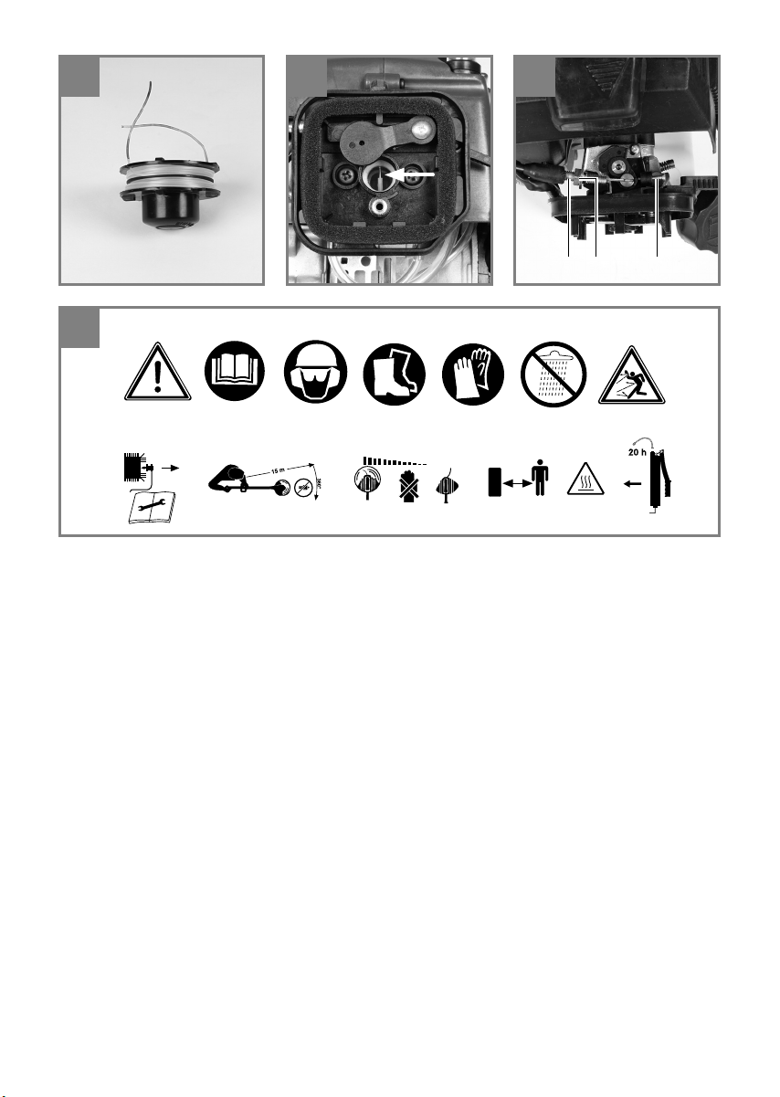
Explanation of the warning signs on the
equipment (Fig. 43):
1. Warning!
2. Read the directions for use before operating
the equipment.
3. Wear protective headgear, goggles and ear
muff s.
4. Wear sturdy, non-slip footwear.
5. Wear safety gloves.
6. Protect the equipment from rain and damp.
7. Be careful of objects being thrown out!
8. Always switch off the equipment and pull out
the spark boot plug before carrying out any
maintenance work.
9. All bystanders must be kept at least 15 m
from the machine.
10. The equipment continues to rotate!
11. Caution: Hot equipment parts. Keep your distance.
12. Add a little grease (gear grease) after every
20 hours in operation!
2. Layout and items supplied
2.1 Layout
1. Cutting blade
2a. Cutting blade guard hood
2b. Guard hood screw (2x)
2c. Cutting line guard hood
3. Line spool with cutting line
4. Drive rod mechanism
5. Connecting piece
6. Gearing
7. Eyelet
8. Handle
9. On/Off switch
10. Handle screw
11. Throttle lock
12. Throttle lever
13. Spark boot plug
14. Starter cable
15. Petrol tank / cap
16. Air fi lter housing cover
17. Choke lever
18. Clip
19. Screw
20. Washer
21. Open-ended wrench size 8/10
22. Allen key size 4mm
23. Allen key size 5mm
24. Nut M10 (left-hand thread)
25. Carrying strap
26. Oil/petrol mixing bottle
27. Multifunction tool
28. Lubricating point
29. Fuel pump „primer“
30. Carrier plate
31. Pressure plate
32. Pressure plate cover
2.2 Items supplied
Please check that the article is complete as specifi ed in the scope of delivery. If parts are missing,
please contact our service center or the nearest
branch of the DIY store where you made your
purchase at the latest within 5 work days after
purchasing the article and upon presentation of
a valid bill of purchase. Also, refer to the warranty
table in the warranty provisions at the end of the
operating instructions.
Open the packaging and take out the equip-
•
ment with care.
- 22 -
Page 9

GB
Remove the packaging material and any
•
packaging and/or transportation braces (if
available).
Check to see if all items are supplied.
•
Inspect the equipment and accessories for
•
transport damage.
If possible, please keep the packaging until
•
the end of the guarantee period.
Important!
The equipment and packaging material are
not toys. Do not let children play with plastic
bags, foils or small parts. There is a danger of
swallowing or suff ocating!
Original operating instructions
•
Safety instructions
•
3. Intended use
The power scythe (using the cutting blade) is
designed for cutting young trees, strong weeds
and undergrowth. The power trimmer (using the
line spool with cutting line) is designed for cutting
lawns, grassed areas and small weeds. The operating instructions as supplied by the manufacturer must be obeyed to ensure that the equipment
is used properly. Any use which is not expressly
permitted in the manual may result in damage
to the equipment and place the user in serious
danger. Be sure to observe the restrictions in the
safety instructions.
The equipment is allowed to be used only for its
prescribed purpose. Any other use is deemed to
be a case of misuse. The user/operator and not
the manufacturer will be liable for any damage or
injuries of any kind resulting from such misuse.
4. Technical data
Engine type ................................2-stroke engine,
.................................. air-cooled, chrome cylinder
Max. engine output .................... 1.25 kW / 1.7 hp
Displacement ........................................ 42.7 cm
Idle engine speed .............................. 3,300 min
Max. engine speed
Scythe: ...............................................9,000 min
Trimmer: .............................................8,000 min
Max. cutting speed
Scythe: ...............................................6,750 min
Trimmer: .............................................6,000 min
Weight (with empty tank) ...............................8 kg
Cutting circle diameter of line ................. Ø 42 cm
Cutting circle diameter of blade ...........Ø 25.5 cm
Cutting line length ...................................... 4.0 m
Cutting line diameter ............................... 2.4 mm
Ignition .................................................Electronic
Drive ........................................Centrifugal clutch
Tank capacity ...........................................1000 ml
Spark plug .......................... L8RTC (NGK BM6A)
Fuel consumption (specifi c) ............... 450 g/kWh
3
-1
-1
-1
-1
-1
Please note that our equipment has not been designed for use in commercial, trade or industrial
applications. Our warranty will be voided if the
equipment is used in commercial, trade or industrial businesses or for equivalent purposes.
Important. Due to the high risk of bodily injury
to the user, the petrol power scythe must not be
used to carry out the following work: to clean dirt
and debris off walkways, or to chop up tree or
hedge clippings. Similarly, the petrol power scythe
must not be used to level out high areas such as
molehills. For safety reasons, the petrol power
scythe must not be used as a drive unit for other
work tools or toolkits of any kind.
Sound and vibration
sound pressure level ......................100 dB(A)
L
pA
uncertainty ...........................................1.5 dB
K
pA
sound power level ..........................108 dB(A)
L
WA
Wear ear-muff s.
The impact of noise can cause damage to hearing.
In operation
Vibration emission value a
K uncertainty = 1.5 m/s
- 23 -
= 6.75 m/s
h
2
2
Page 10

GB
Reduce noise generation and vibration to a
minimum!
Use only equipment that is in perfect condi-
•
tion.
Maintain and clean the equipment regularly.
•
Adopt your way of working to the equipment.
•
Do not overload the equipment.
•
Have the equipment checked if necessary.
•
Switch off the equipment when not in use.
•
Wear gloves.
•
Wear eye and hearing protection
•
5. Assembly
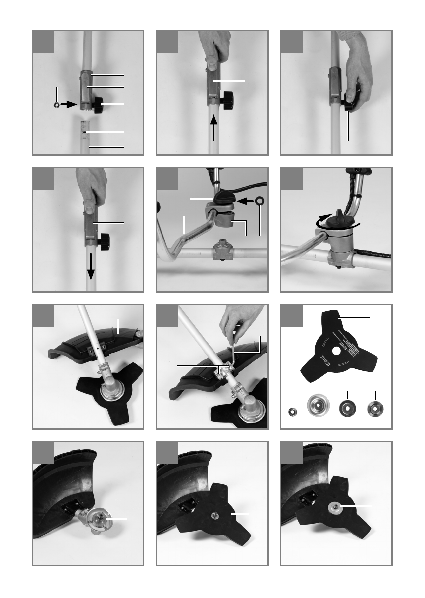
5.1 Mounting the blade guard hood
Important: The cutting blade guard hood must be
fi tted if you wish to work with the cutting blade.
The guard hood for the cutting blade must be installed as shown in Figures 10-11.
5.2 Joining the drive rod mechanism to the
connecting piece (Fig. 4-7)
Fit the handle screw (Item 10) as shown in Fig.
4. Open the handle screw and push the drive rod
mechanism (Item 4) into the connecting piece
(Item 5). Make sure that the centering lever (Item
R) latches in the guide hole (Item H). Tighten the
handle screw. To take apart, undo the handle
screw. Press the centering lever and simultaneously pull the drive rod mechanism out of the
connecting piece.
5.3 Fitting / Replacing the cutting blade
The procedure for fi tting the cutting blade is
shown in Figures 12-18. To dismantle, proceed in
reverse order.
Fit the carrier plate 30) onto the spline shaft
•
(Fig. 13)
Secure the cutting blade (1) on the carrier
•
plate (Fig. 14)
Place the pressure plate (31) over the thread
•
of the spline shaft (Fig. 15)
Plug on the cover of the pressure plate (32)
•
(Fig. 16)
Look for the hole in the carrier plate, line up
•
with the notch underneath and lock with the
supplied Allen key (22) in order to now tighten
the nut (24) (Fig. 17/18) Important: Left-hand
thread
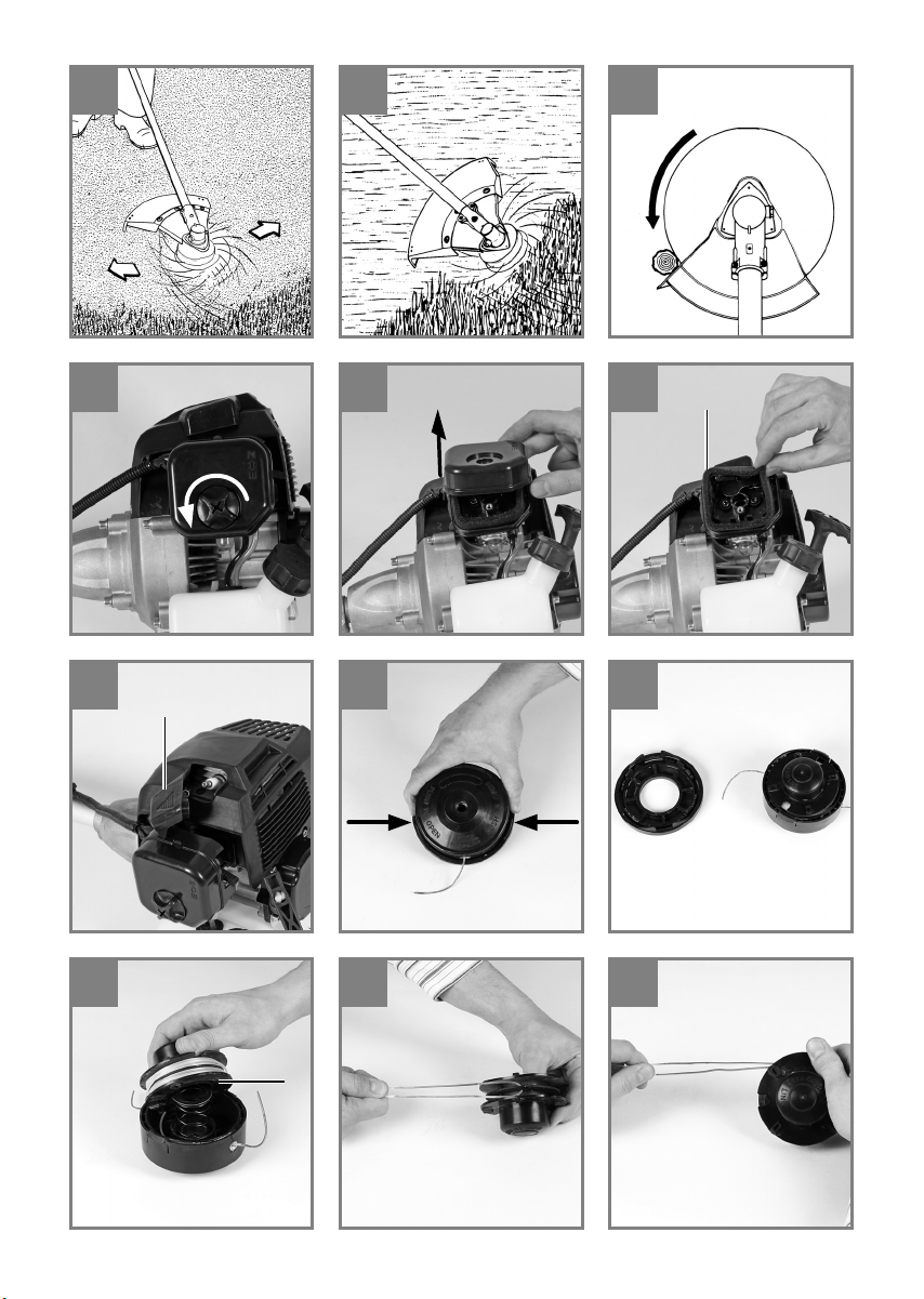
fi tted in addition if you want to work with the cutting line.
The procedure for fi tting the guard hood for the
cutting line is shown in Figures 19-20. A blade
(Fig. 19/ Item F) on the underside of the guard
hood automatically cuts the cutting line to the
optimum length. It is covered by a guard (Fig.
19/Item G). Remove the guard before you start
working and replace it when you have fi nished
working.
5.5 Fitting the handle
Fit the handle as shown in Fig. 8-9.
5.6 Fitting / Replacing the line spool
The procedure for fi tting the line spool is shown in
Figure 21. To dismantle, proceed in reverse order.
Look for the hole in the carrier plate, line up with
the notch underneath and lock with the supplied
Allen key (22) in order to now screw the line spool
onto the thread. Important: Left-hand thread
6. Before starting
Each time before use, check the following:
That there are no leaks in the fuel system.
•
That the equipment is in perfect condition and
•
that the safety devices and cutting devices
are complete.
That all screws are securely fastened.
•
That all moving parts move smoothly.
•
6.1 Fuel and oil
Recommended fuels
Use only a mixture of unleaded petrol and special
2-stroke engine oil. Mix the fuel mixture as indicated in the fuel mixing table.
Important: Do not use a fuel mixture which has
been stored for longer than 90 days. Important:
Never use 2-stroke oil with a recommended mixing ratio of 100:1. The manufacturer’s warranty
will be voided in case of engine damage due to
inadequate lubrication. Important: Only use containers designed and approved for the purpose to
transport and store fuel.
Pour the correct quantities of petrol and 2-stroke
oil into the mixing bottle (see scale printed on the
bottle). Then shake the bottle well.
5.4 Fitting the cutting line guard hood to the
blade guard hood
Important: The cutting line guard hood must be
- 24 -
Page 11

GB
6.2 Fuel mixing table
Mixing procedure: 40 parts petrol to 1 part oil
Petrol 2-stroke oil
1 liter 25 ml
5 liters 125 ml
7. Operation
Please note that the statutory regulations governing noise abatement may diff er from one loca-
tion to another.
Before starting up the equipment remove the protective caps from the cutting blade.
7.1 Starting with a cold engine
Fill the tank with the required amount of oil/petrol
mix. See „Fuel and oil“.
1. Set the equipment down on a hard, level surface.
2. Press the fuel pump (primer) (Fig. 2/Item 29)
10 times.
3. Move the On/Off switch (Fig. 2/Item 9) to „I“.
4. Set the choke lever (Fig. 2/Item 17) to „ “.
5. Hold the equipment fi rmly and pull out the
starter cable (Fig. 2/Item 14) until you feel it
begin to resist. Then tug sharply on the starter
cable 4 times. The equipment should start.
Important: Never allow the starter line to snap
back. This may result in damage.
Once the engine has started, allow the equipment to warm up for 10 seconds.
Important: Since the choke lever is secured,
the cutting tool starts to operate when the
engine is started.
Then release the choke lever by actuating the
throttle lever once.
6. If the engine does not start up, repeat steps
4-6 above.
Please note: If the engine does not start up even
after several attempts, read the section „Engine
troubleshooting“.
Please note: Always pull the starter cord out in
a straight line. If it is pulled out at an angle, then
friction will occur on the eyelet. As a result of this
friction, the cable will become frayed and will
wear away faster. Always hold the starter handle
when the cable retracts.
Never allow the cable to snap back when it has
been pulled out.
7.2 Starting with a warm engine
(The equipment has been idle for less than 15-20
min.)
1. Set the equipment down on a hard, level surface.
2. Switch the On/Of switch to „I“.
3. Secure the throttle lever (in the same way as
described in „Starting with a cold engine“).
4. Hold the equipment fi rmly and pull out the
starter cable until you feel it start to resist.
Then tug sharply on the starter cable. The
equipment should start after 1-2 tugs. If the
equipment does not start after 6 pulls, repeat
steps 1 – 6 of the procedure for starting the
engine from cold.
7.3 Switching off the engine
Emergency Stop procedure:
If it becomes necessary to stop the equipment immediately, set the On/Off switch to „Stop“ or „0“.
Normal procedure:
Let go of the throttle lever and wait until the engine has changed to idling speed. Then set the On/
Off switch to „Stop“ or „0“.
7.4 Fitting the shoulder strap
Important! Always use the shoulder strap when
working with the equipment. Switch off the equip-
ment before you take off the shoulder strap (risk
of injury).
1. Slip the shoulder strap over your shoulder.
2. Adjust the length of the shoulder strap so that
the strap attachment is at waist level.
3. To establish the optimum length of the carrying strap, you should then make a few swinging movements without starting the engine
(Fig. 25).
7.5 Work practice
Practice all the work steps with the engine switched off before you start to use the equipment.
- 25 -
Page 12

GB
8. Working with the petrol power
scythe
Extending the cutting line
Caution! Do not use any kind of metal wire or
metal wire encased in plastic in the line spool.
This may cause serious injuries to the user.
To extend the cutting line, run the engine at full
speed and tap the line spool on the ground. This
will automatically extend the line. The blade on
the safety shield will cut the line to the appropriate
length (Fig. 26).
Important: Remove all grass and weed remnants
at regular intervals to prevent the shaft tube overheating. Lawn, grass and weed remnants become
trapped under the safety shield (Fig. 27) and
prevent the shaft tube from receiving adequate
ventilation. Remove the remnants carefully using
a screwdriver or the like.
Diff erent cutting methods
When the equipment is correctly assembled it
will cut weeds and long grass in places which are
diffi cult to access, e.g. along fences, walls and
foundations and also around trees. It can also
be used for „mowing“ down vegetation so that a
garden can be better prepared or a certain area
cleared down to the soil.
Please note: Even if it is used carefully, cutting
around foundations, stone or concrete walls, etc.
will result in the line suff ering more than normal
wear.
Trimming/mowing
Swing the trimmer from side to side in a scything
motion. Always keep the line spool parallel to the
ground. Check the site and decide which cutting
height you require. Guide and hold the line spool
at the required height to obtain an even cut (Fig.
28).
Low trimming
Hold the trimmer right in front of you at a slight
angle so that the underside of the line spool is
above the ground and the line strikes the correct
target. Always cut away from yourself. Never draw
the trimmer towards yourself.
Cutting along fences/foundations
Approach wire mesh fences, lath fences, natural
stone walls and foundations slowly so that you
can cut close to them without striking the obstacle with the line. If, for example, the line strikes
stones, stone walls or foundations, it will wear or
fray.
If the line strikes wire fencing, it will break.
Trimming around trees
When trimming around tree trunks, approach
slowly so that the line does not strike the bark.
Walk around the tree, cutting from left to right. Approach grass or weeds with the tip of the line and
tilt the line spool forwards slightly. Warning! Take
extreme care during mowing work. When doing
such work keep a distance of 30 meters between
yourself and other people or animals.
Mowing
When mowing, you want to cut all the vegetation
down to the ground. To do this, set the line spool
at an angle of 30° to the right. Place the handle in
the required position. Remember the increased
risk of injury to the user, watchers and animals,
and the danger of damaging property due to objects (for example stones) being thrown up (Fig.
29).
Warning! Do not use the equipment to remove
objects from footpaths, etc. The equipment is a
powerful tool and can throw small stones and
other objects a distance of 15 meters or more,
causing injuries and damage to cars, houses and
windows.
Sawing
The equipment is not suitable for sawing.
Jamming
If the cutting blade jams as a result of attempting
to cut vegetation that is too dense, switch off the
engine immediately. Remove the grass and scrub
from the equipment before you restart it.
- 26 -
Page 13

GB
Preventing recoil
When you work with the blade, there is a risk of
recoil if it strikes solid objects such as tree trunks,
branches, tree stumps, stones or the like. This will
throw the equipment backwards in the direction
opposite to the rotation of the tool. This can cause
you to lose control of the equipment. Do not use
the blade near fences, metal posts, boundary
stones or foundations. For cutting dense stalks,
position the blade as shown in Fig. 30 to prevent
recoil.
9. Maintenance
Always switch off the equipment and pull out
the spark boot plug (13) before carrying out any
maintenance work.
9.1 Replacing the line spool/cutting line
1. Dismantle the line spool (3) as described in
section 5.6. Press the spool together (Fig. 35)
and remove one half of the housing (Fig. 36).
2. Take the spool plate (K) out of the line spool
housing (Fig. 37).
3. Remove any remaining cutting line.
4. Place the new cutting line in the center and
hang the loop which has formed into the recess in the spool splitter. (Fig. 38)
5. Wind the line onto the spool counter-clockwi-
se and under tension. The spool splitter will
separate the two halves of the line. (Fig. 39)
6. Hook the last 15cm of the two ends of the
line onto the opposite lying line holders of the
spool plate. (Fig. 40)
7. Thread the two ends of the line through the
metal eyelets in the line spool housing (Fig.
37).
8. Press the spool plate into the line spool
housing (Fig. 36).
9. Pull the two line ends sharply to release them
from the line holders.
10. Join the housing parts together again.
11. Cut the excess line to a length of around
13cm. This will reduce the load on the engine
when starting and warming up.
12. Remount the line spool (see section 5.6). If
you are replacing the complete line spool,
skip points 3-6.
9.2 Grinding the safety hood blade
The safety hood blade can become blunt over
time. When you notice this, undo the screw holding the safety hood blade on the safety hood.
Clamp the blade in a vise. Sharpen the blade with
a fl at fi le and make sure that the angle of the cut-
ting edge is not altered in the process. File in one
direction only.
9.3 Maintenance of the air fi lter (Fig. 31-33)
Soiled air fi lters reduce the engine power by
supplying too little air to the carburetor. Regular
checks are therefore essential. The air fi lter (T)
should be checked after every 25 hours of use
and cleaned if necessary. If the air contains a
lot of dust, the air fi lter should be checked more
frequently.
1. Remove the air fi lter cover (Fig. 31-32).
2. Remove the air fi lter (Fig. 33).
3. Clean the air fi lter by tapping it or blowing it
out.
4. Assemble in reverse order.
Important: Never clean the air fi lter with petrol or
infl ammable solvents.
9.4 Maintenance of the spark plug (Fig. 34)
Spark plug sparking gap = 0.6mm. Tighten the
spark plug with a torque of 12 to 15 Nm. Check
the spark plug for dirt and grime after 10 hours of
operation and if necessary clean it with a copper
wire brush. Thereafter service the spark plug after
every 50 hours of operation.
1. Pull out the spark boot plug (Fig. 13).
2. Remove the spark plug (Fig. 34) with the supplied multifunction tool (27).
3. Assemble in reverse order.
9.5 Carburetor settings
Important! Settings on the carburetor may only
be made by authorized customer service personnel.
The air fi lter cover must be removed before car-
rying out any work on the carburetor, as shown in
Fig. 31 and 32.
- 27 -
Page 14

GB
9.6 Setting the throttle cable
If the maximum speed of the equipment drops
over time and you have ruled out all the other
possible causes listed in section 12 „Troubleshooting“, it may be necessary to adjust the throttle
cable. First of all check whether the carburetor
opens fully when the throttle handle is pressed
right through. This is the case if the carburetor slide (Fig. 41) is completely opened when the throttle is fully activated. Figure 41 shows the correct
setting. If the carburetor slide is not completely
open, it must be adjusted. The following steps are
required to adjust the throttle cable:
Undo the lock nut (Fig. 42/Item C) a few turns.
Turn out the adjusting screw (Fig. 42/Item D) until
the carburetor slide is completely open when the
throttle is fully activated, as shown in Figure 41.
Retighten the lock nut.
9.7 Setting the idling speed
Important! Set the idling speed when the equipment is warm.
If the engine stalls when the throttle is not pressed
and you have ruled out all the other possible
causes listed in section 12 „Troubleshooting“, the
idling speed must be adjusted. To do this, turn
the idling speed screw (Fig. 42/Item E) clockwise
until the equipment runs smoothly at idling speed.
If the idling speed is so fast that the cutting tool
turns as well, it has to be reduced by turning the
idling speed screw for as long as is required for
the cutting tool to stop turning as well.
9.8 Applying grease to the gear unit
After every 20 hours of use add a little gear grease (approx. 10 g.) at the lubrication nipple (Fig.
28/Item 21).
10. Cleaning, storage, transport and
ordering of spare parts
10.1 Cleaning
Clean the equipment as required with a damp
•
cloth and, if necessary, mild washing up
liquid.
Important!
Always pull out the spark boot plug each time
before carrying out any cleaning. Never immerse
the equipment in water or other liquids in order to
clean it.
Store the chainsaw in a safe and dry place out of
the reach of children.
10.2 Storage
Important: Never put the equipment into storage
for longer than 30 days without carrying out the
following steps.
Storing the equipment
If you intend to store the equipment for longer
than 30 days, the equipment must be prepared
accordingly. Otherwise the fuel still remaining in
the carburetor will evaporate and leave a rubbery
sediment. This can cause problems when starting
up the equipment and may require expensive
repairs.
1. Slowly remove the fuel tank cap to release
any pressure that may have formed in the
tank. Carefully empty the tank.
2. To remove the fuel from the carburetor, start
the engine and let it run until the equipment
stops.
3. Leave the engine to cool (approx. 5 minutes).
4. Remove the spark plug (see section 9.4).
5. Add one teaspoon of 2-stroke engine oil into
the combustion chamber. Slowly pull the starter cord several times to apply a layer of oil
to all internal components. Fit the spark plug
again.
Note: Store the equipment in a dry place and
far away from possible ignition sources such as
an oven, a gas-fi red hot water boiler, a gas-fi red
dryer, etc.
- 28 -
Page 15

Putting the equipment back into operation
1. Remove the spark plug (see section 9.4).
2. Quickly tug on the starter cord to remove excess oil from the combustion chamber.
3. Clean the spark plug and check that the
electrode gap is correct, or insert a new spark
plug with the correct electrode gap.
4. Prepare the equipment for operation.
5. Fill the tank with the relevant mixture of fuel
and oil. See the section „Fuel and oil“.
10.3 Transport
To transport the machine, empty the petrol tank
as described in section 10. Clean coarse dirt off
the equipment with a brush or hand brush. Dismantle the drive rod mechanism as described in
section 5.2.
10.4 Ordering spare parts
Please provide the following information on all
orders for spare parts:
Model/type of the equipment
•
Article number of the equipment
•
ID number of the equipment
•
Part number of the required spare part
•
For our latest prices and information please go to
www.isc-gmbh.info
GB
11. Disposal and recycling
The equipment is supplied in packaging to prevent it from being damaged in transit. The raw
materials in this packaging can be reused or
recycled. The equipment and its accessories are
made of various types of material, such as metal
and plastic. Defective components must be disposed of as special waste. Ask your dealer or your
local council.
- 29 -
Page 16

GB
12. Troubleshooting guide
The table below contains a list of fault symptoms and explains what you can do to remedy the problem
if your equipment fails to work properly. If the problem still persists after working through the list, please
contact your nearest service workshop.
Fault Possible cause Remedy
The equipment
does not start
The equipment
starts but does
not develop its full
power
The engine does
not run smoothly
Engine smokes excessively
- Correct starting procedure not followed
- Sooted or damp spark plug
- Incorrect carburetor setting
- Incorrect choke lever setting
- Soiled air fi lter
- Incorrect carburetor setting
- Incorrect electrode gap on the
spark plug
- Incorrect carburetor setting
- Incorrect fuel mix
- Incorrect carburetor setting
- Follow the instructions for starting
- Clean the spark plug or replace it
with a new one
- Contact an authorized customer
service outlet or send the equipment to ISC GmbH
- Set the choke lever to „
- Clean the air fi lter
- Contact an authorized customer
service outlet or send the equipment to ISC GmbH
- Clean the spark plug and adjust the
electrode gap, or fi t a new spark
plug
- Contact an authorized customer
service outlet or send the equipment to ISC GmbH
- Use the correct fuel mix (see fuel
mixing table)
- Contact an authorized customer
service outlet or send the equipment to ISC GmbH
“
- 30 -
Page 17

GB
The reprinting or reproduction by any other means, in whole or in part, of documentation and papers
accompanying products is permitted only with the express consent of the iSC GmbH.
Subject to technical changes
- 31 -
Page 18

GB
Warranty provisions
iSC GmbH or the DIY store where you made you purchase guarantees the repair of defects or replacement of the equipment in accordance with the overview below. Statutory guarantee claims are unaff ec-
ted.
Category Example Warranty
Defect with regard to material or
construction
Wear parts* Spark plug, air fi lter 6 months
Consumables* Cutting blade, line spool with
Missing parts 5 work days
* Not necessarily included in the scope of delivery!
For consumables, wear parts and missing parts iSC GmbH guarantees the correction of defects or a
new delivery only if the defect is reported within 24 hours (consumables), 5 work days (missing parts) or
6 months (wear parts) after purchase and the purchase date is verifi ed with the bill.
In case of defects concerning the material or construction, we kindly request you to submit the equipment together with the fully completed warranty card supplied with the equipment. It is important that
you enter an exact description of the defect.
To do so, answer the following questions:
Did the equipment work at all or was it defective from the beginning?
•
Did you notice anything (symptom or defect) prior to the failure?
•
What malfunction does the equipment have in your opinion (main symptom)?
•
Describe this malfunction.
cutting line
24 months
Warranty only in case of an immediate defect (24 hours after
purchase / date on the bill)
- 32 -
Page 19

GB
Warranty certifi cate
Dear Customer,
All of our products undergo strict quality checks to ensure that they reach you in perfect condition. In the
unlikely event that your device develops a fault, please contact our service department at the address
shown on this guarantee card. Of course, if you would prefer to call us then we are also happy to off er
our assistance under the service number printed below. Please note the following terms under which
guarantee claims can be made:
1. These guarantee terms cover additional guarantee rights and do not aff ect your statutory warranty
rights. We do not charge you for this guarantee.
2. Our guarantee only covers problems caused by material or manufacturing defects, and it is restricted to the rectifi cation of these defects or replacement of the device. Please note that our devices
have not been designed for use in commercial, trade or industrial applications. Consequently, the
guarantee is invalidated if the equipment is used in commercial, trade or industrial applications or
for other equivalent activities. The following are also excluded from our guarantee: compensation for
transport damage, damage caused by failure to comply with the installation/assembly instructions
or damage caused by unprofessional installation, failure to comply with the operating instructions
(e.g. connection to the wrong mains voltage or current type), misuse or inappropriate use (such as
overloading of the device or use of non-approved tools or accessories), failure to comply with the
maintenance and safety regulations, ingress of foreign bodies into the device (e.g. sand, stones or
dust), eff ects of force or external infl uences (e.g. damage caused by the device being dropped) and
normal wear resulting from proper operation of the device. This applies in particular to rechargeable
batteries for which we nevertheless issue a guarantee period of 12 months. The guarantee is rendered null and void if any attempt is made to tamper with the device.
3. The guarantee is valid for a period of 2 years starting from the purchase date of the device. Guarantee claims should be submitted before the end of the guarantee period within two weeks of the defect being noticed. No guarantee claims will be accepted after the end of the guarantee period. The
original guarantee period remains applicable to the device even if repairs are carried out or parts are
replaced. In such cases, the work performed or parts fi tted will not result in an extension of the gua-
rantee period, and no new guarantee will become active for the work performed or parts fi tted. This
also applies when an on-site service is used.
4. In order to assert your guarantee claim, please send your defective device postage-free to the
address shown below. Please enclose either the original or a copy of your sales receipt or another dated proof of purchase. Please keep your sales receipt in a safe place, as it is your proof of
purchase. It would help us if you could describe the nature of the problem in as much detail as possible. If the defect is covered by our guarantee then your device will either be repaired immediately
and returned to you, or we will send you a new device.
Of course, we are also happy off er a chargeable repair service for any defects which are not covered by
the scope of this guarantee or for units which are no longer covered. To take advantage of this service,
please send the device to our service address.
Also refer to the restrictions of this warranty concerning wear parts/consumables and missing parts as
set forth in the warranty conditions in these operating instructions.
- 33 -
Page 20

ISC GmbH · Eschenstraße 6 · D-94405 Landau/Isar
Konformitätserklärung
D erklärt folgende Konformität gemäß EU-Richtlinie und
Normen für Artikel
GB explains the following conformity according to EU directi-
ves and norms for the following product
F déclare la conformité suivante selon la directive CE et les
normes concernant l’article
I dichiara la seguente conformità secondo la direttiva UE e
le norme per l’articolo
NL verklaart de volgende overeenstemming conform EU
richtlijn en normen voor het product
E declara la siguiente conformidad a tenor de la directiva y
normas de la UE para el artículo
P declara a seguinte conformidade, de acordo com a
directiva CE e normas para o artigo
DK attesterer følgende overensstemmelse i medfør af
EU-direktiv samt standarder for artikel
S förklarar följande överensstämmelse enl. EU-direktiv och
standarder för artikeln
FIN vakuuttaa, että tuote täyttää EU-direktiivin ja standardien
vaatimukset
EE tõendab toote vastavust EL direktiivile ja standarditele
CZ vydává následující prohlášení o shodě podle směrnice EU
a norem pro výrobek
SLO potrjuje sledečo skladnost s smernico EU in standardi za
izdelek
SK vydáva nasledujúce prehlásenie o zhode podľa smernice
EÚ a noriem pre výrobok
H a cikkekhez az EU-irányvonal és Normák szerint a
következő konformitást jelenti ki
Benzin-Motorsense GH-BC 43 AS (Einhell)
87/404/EC_2009/105/EC
2005/32/EC_2009/125/EC
2006/95/EC
2006/28/EC
X
2004/108/EC
2004/22/EC
1999/5/EC
97/23/EC
90/396/EC_2009/142/EC
89/686/EC_96/58/EC
2011/65/EC
X
2006/42/EC
Annex IV
Notifi ed Body:
Notifi ed Body No.:
Reg. No.:
X
2000/14/EC_2005/88/EC
X
Annex V
Annex VI
Notifi ed Body: LWA = 106,5 dB (A); guaranteed LWA = 108 dB (A)
P = 1,25 KW; L/Ø = cm
Notifi ed Body:
X
2004/26/EC
Emission No.: e11*97/68SA*2010/26*1409*00
PL deklaruje zgodność wymienionego poniżej artykułu z
następującymi normami na podstawie dyrektywy WE.
BG декларира съответното съответствие съгласно
Директива на ЕС и норми за артикул
LV paskaidro šādu atbilstību ES direktīvai un standartiem
LT apibūdina šį atitikimą EU reikalavimams ir prekės normoms
RO declară următoarea conformitate conform directivei UE şi
normelor pentru articolul
GR δηλώνει την ακόλουθη συμμόρφωση σύμφωνα με την
Οδηγία ΕΚ και τα πρότυπα για το προϊόν
HR potvrđuje sljedeću usklađenost prema smjernicama EU i
normama za artikl
BIH potvrđuje sljedeću usklađenost prema smjernicama EU i
normama za artikl
RS potvrđuje sledeću usklađenost prema smernicama EZ i
normama za artikal
RUS следующим удостоверяется, что следующие продукты
соответствуют директивам и нормам ЕС
UKR проголошуєпро зазначену нижче відповідність виробу
директивам та стандартам ЄС на виріб
MK ја изјавува следната сообрзност согласно
ЕУ-директивата и нормите за артикли
TR Ürünü ile ilgili AB direktifl eri ve normları gereğince aşağıda
açıklanan uygunluğu belirtir
N erklærer følgende samsvar i henhold til EU-direktivet og
standarder for artikkel
IS Lýsir uppfyllingu EU-reglna og annarra staðla vöru
Standard references: EN ISO 11806; EN ISO 14982
Landau/Isar, den 10.06.2013
First CE: 13 Archive-File/Record: NAPR008004
Art.-No.: 34.019.73 I.-No.: 11013 Documents registrar: Robert Mayn
Subject to change without notice Wiesenweg 22, D-94405 Landau/Isar
- 168 -
Sun/Product-ManagementWeichselgartner/General-Manager
Page 21

- 169 -
Page 22

- 170 -
Page 23

- 171 -
Page 24

EH 06/2013 (01)
 Loading...