

Page 1

Assembly Manual
Tensor 4D
Page 2

Table of Contents
Introduction ..................................................... 2
Specifications .................................................. 2
Warning ......................................................... 3
Additional Required Equipment ......................... 3
Additional Tools and Adhesives ......................... 3
Contents of Kit/Parts Layout ..............................4
Required Items ................................................ 5
Other E-flite™ Accessories ................................ 5
Before Starting Assembly .................................. 5
Using the Manual ............................................ 5
Warranty Information ....................................... 6
Fuselage Assembly ...........................................7
Radio Installation ........................................... 11
Wing Installation ...........................................18
Carbon Rod Installation .................................. 21
Aileron Servo Installation ................................ 26
Installing the Electronics .................................. 32
Landing Gear Installation ................................ 35
Final Assembly ..............................................37
Control Throws ..............................................38
Center of Gravity ........................................... 39
General Set-up Tips for 3D Flight ....................39
Trimming and Flying the Tensor 4D ..................41
Basic Guide for Learning to Fly 3D Maneuvers . 43
2004 Official AMA
National Model Aircraft Safety Code ............... 46
Introduction
A true breakthrough in electric flight, the Tensor 4D
lightweight design takes extreme 3D aerobatics to a
new level. The Tensor is designed by Aerodynamicist
George Hicks, a top-level Unlimited Aerobatic ace.
The Tensor features unique side force generators for
maximum yaw authority and knife–edge flight, light
wing loading, carbon fiber wing and tail support
for reinforcement and added strength, and precision
laser cut pre-painted flat foam construction.
Specifications
Wingspan: 27 in (685 mm)
Length: 30 in (760 mm)
Wing Area: 393 sq in (25 sq dm)
Weight w/o Battery: 8 oz (230 g)
Weight w/Battery: 9.5 oz (270 g)
2
Page 3

Warning
An RC aircraft is not a toy! If misused, it can cause
serious bodily harm and damage to property. Fly
only in open areas, preferably at AMA (Academy of
Model Aeronautics) approved flying sites, following
all instructions included with your radio.
Additional Required Equipment
Recommended JR® Systems
Servos: JR 241 Sub-micro servo (3)
Receiver: JR R610M 6-channel micro FM Rx or R610UL
Radio: JR 4-channel system
Battery and Speed Control Requirements
Li-Po Battery: 7.4V 860 2-Cell
Speed Control: 10 amp brushless
Additional Tools and Adhesives
Tools
Square
Hobby knife
Ruler
T-pin
Razor saw
Drill bit: 1/16", 1/8"
Drill
Small Phillips screwdriver
Motor/Gearbox
E-flite™ Park 370 Outrunner, 1080KV
Propeller: 10x4.7
Adhesives
Foam-safe CA
Servo tape
Thin CA
3
Page 4
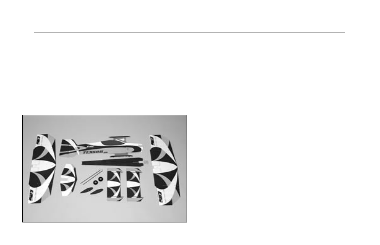
Contents of Kit/Parts Layout
Large Replacement Parts:
EFL2101 Wing Set w/Struts
EFL2102 Vertical Fuselage w/Rudder
EFL2103 Horizontal Fuselage
EFL2104 Tail Assembly
EFL2105 Wheel Pants
EFL2106 Firewall Mount w/Hardware
EFL2110 Landing Gear
Small Replacement Parts:
EFL2108 Carbon Fiber Wing Supports
EFL2109 Pushrods and Control Rods
EFL2107 Nylon String (120")
EFLA200 Micro Control Horns
EFLA201 Micro Pushrod Keepers
EFLA202 Micro Control Connectors
EFLA221 Foam Park Wheels, 1.5"
EFLA2086 Hook and Loop Tape
4
Page 5

Required Items
Before Starting Assembly
EFLP1047 10x4.7 Slow Flyer Propeller (2)
JRP4487 Quattro UL, R610UL, 2-S241
JRPS241 S241 Sub-micro Servo
EFLB1000 7.4v 860mAh 2-cell Li-Po, JST
THP13602SJ 7.4v 860mAh 2-cell Li-Po, JST
EFLM1200 Park 370 Outrunner, 1080KV
CSEPHX10L Phoenix 10-Amp Brushless ESC
Other E-flite™ Accessories
EFLM1205 Park 370 Outrunner, 1360KV
EFLC3005 Celectra™ 1- to 3-cell
Li-Po Charger
EFLM110 Power Meter
EFLA208 Foam CA 1 oz/
Activator 2 oz pack
Before beginning the assembly of your Tensor 4D,
remove each part from its bag for inspection. Closely
inspect the fuselage, wing panels, rudder and
stabilizer for damage. If you find any damaged or
missing parts, contact the place of purchase.
Using the Manual
This manual is divided into sections to help make
assembly easier to understand, and to provide
breaks between each major section.
Remember to take your time and follow
the directions.
5
Page 6

Warranty Information
Horizon Hobby, Inc. guarantees this kit to be free
from defects in both material and workmanship at the
date of purchase. This warranty does not cover any
component parts damage by use or modification. In
no case shall Horizon Hobby’s liability exceed the
original cost of the purchased kit. Further, Horizon
Hobby reserves the right to change or modify this
warranty without notice.
In that Horizon Hobby has no control over the final
assembly or material used for the final assembly,
no liability shall be assumed nor accepted for any
damage resulting from the use of the final assembled
product. By the act of using the assembled product,
the user accepts all resulting liability.
Please note that once assembly of the model has
been started, you must contact Horizon Hobby, Inc.
directly regarding any warranty question. Please
do not contact your local hobby shop regarding
warranty issues, even if that is where you purchased
it. This will enable Horizon to better answer your
questions and service you in the event that you may
need any assistance.
If the buyer is not prepared to accept the liability
associated with the use of this product, the buyer
is advised to return this kit immediately in new and
unused condition to the place of purchase.
Horizon Hobby, Inc.
4105 Fieldstone Road
Champaign, Illinois 61822
(877) 504-0233
www.horizonhobby.com
6
Page 7
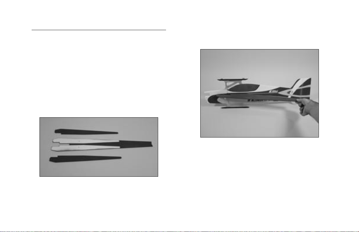
Fuselage Assembly
Required Parts
Vertical fuselage Horizontal fuselage
Horizontal fuselage support (2) Elevator/stabilizer
Carbon elevator joiner brace
Required Tools and Adhesives
Foam-safe CA Square
1. Carefully remove the horizontal fuselage
supports from the horizontal fuselage.
2. Slide the horizontal fuselage partially into
position. The unpainted side will face the bottom
of the fuselage.
7
Page 8
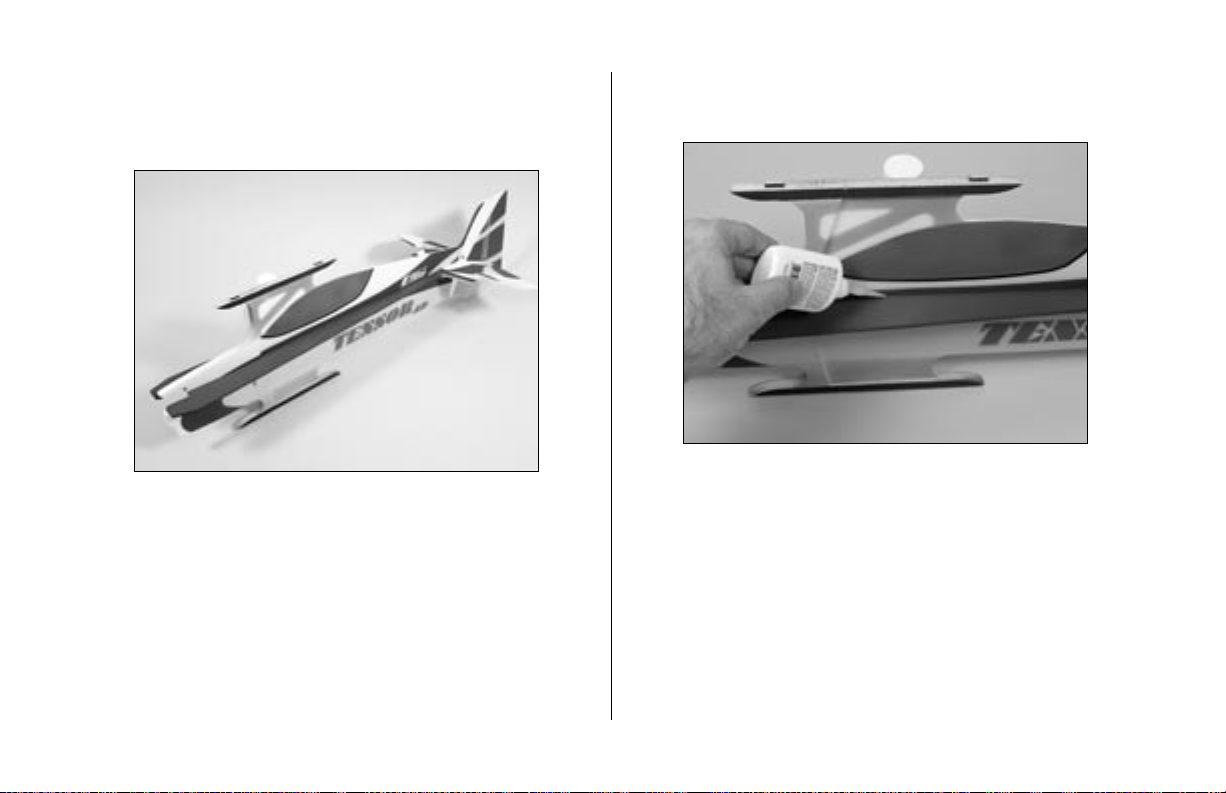
3. Use foam-safe CA to attach the carbon
stabilizer joiner brace to the bottom of
the elevator.
4. Slide the elevator/stabilizer assembly
into position.
8
Page 9
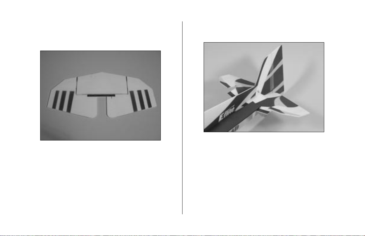
5. Slide the horizontal fuselage fully forward in the
fuselage. Center it in the main fuselage, making
sure the notch at the rear fits with the stabilizer.
Note: There are small notches along the center
of the horizontal fuselage to aid in alignment.
6. Use foam-safe CA to glue the horizontal
fuselage to the vertical fuselage.
Note: Do not use accelerator unless you are
sure it will not harm the foam or paint on
your model.
9
Page 10

7. Slide the stabilizer forward against the
horizontal fuselage. Use a square to check the
alignment to the fuselage.
8. Use foam-safe CA to glue the stabilizer
into position.
9. Use foam-safe CA to glue the horizontal
fuselage supports into position on the bottom of
the fuselage support.
10
Page 11
Radio Installation
Required Parts
Fuselage assembly
Micro control connector (2)
Control connector backplate (2)
2mm x 4mm screw (2)
Micro control horn (2)
Micro control horn backplate (2)
.065" x 16" carbon pushrod (2)
1/32" x 2" pushrod end (4)
Micro pushrod keeper (2)
String
Required Tools and Adhesives
Foam-safe CA Servo tape
Razor saw
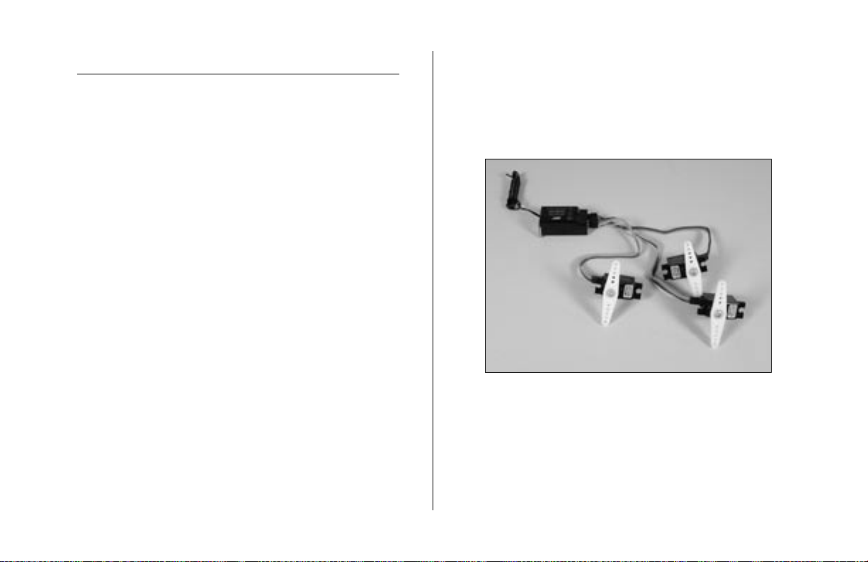
1. Plug in the aileron, elevator and rudder servos
to the receiver following the instructions from
your radio system. Turn on the radio and center
the trims on the transmitter. Install long servo
arms on the servos.
11
Page 12

Note: The control horns can be modified
to greatly increase surface throws. Remove the
back flange of the horn using scissors. Install
the horn by sliding the horn through the control
surface. Slide the backplate onto the horn and
use foam-safe CA to glue the backplate into
position.
2. Attach the micro control horn to the elevator
using the micro control horn backplate. Place a
few drops of foam-safe CA on the backplate to
ensure its security.
12
Page 13

3. Install the rudder control horn, making sure it is
on the opposite side of the elevator horn.
4. Trim one of the servo arms from the elevator
servo. Cut a hole in the horizontal fuselage
support to fit your servo. The servo must rest
flush with the support. Use double-sided tape or
foam-safe CA to attach the servo to the fuselage
support. The arm faces the front of the fuselage,
and the aft edge of the servo aligns with the aft
edge of the fuselage spine support.
13
Page 14
5. Repeat Step 4 for the rudder servo.
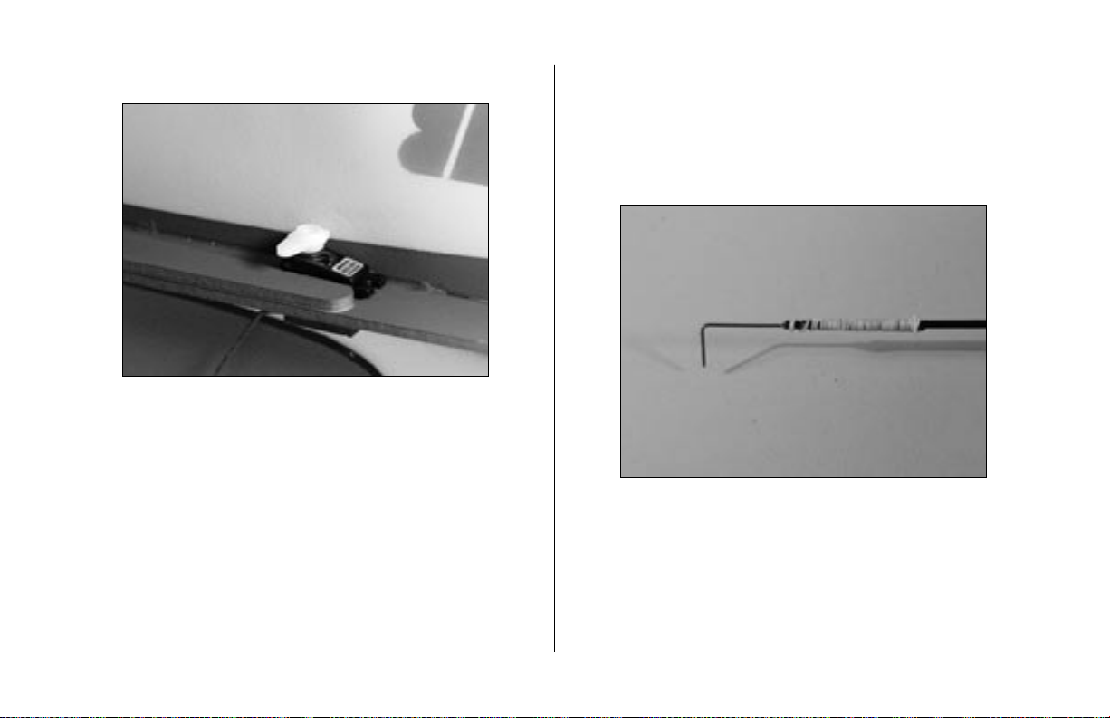
6. Prepare one of the .065" x 16" carbon
pushrods by attaching one of the 1/32" x 2"
pushrod ends using 10" of string and thin CA.
Make a 90-degree bend 1/4" from the end of
the pushrod end.
14
Page 15
7. Pass the bend in the pushrod through on of the
holes in the elevator control horn. Use the outer
hole for minimum throw and the inner hole for
maximum throw.
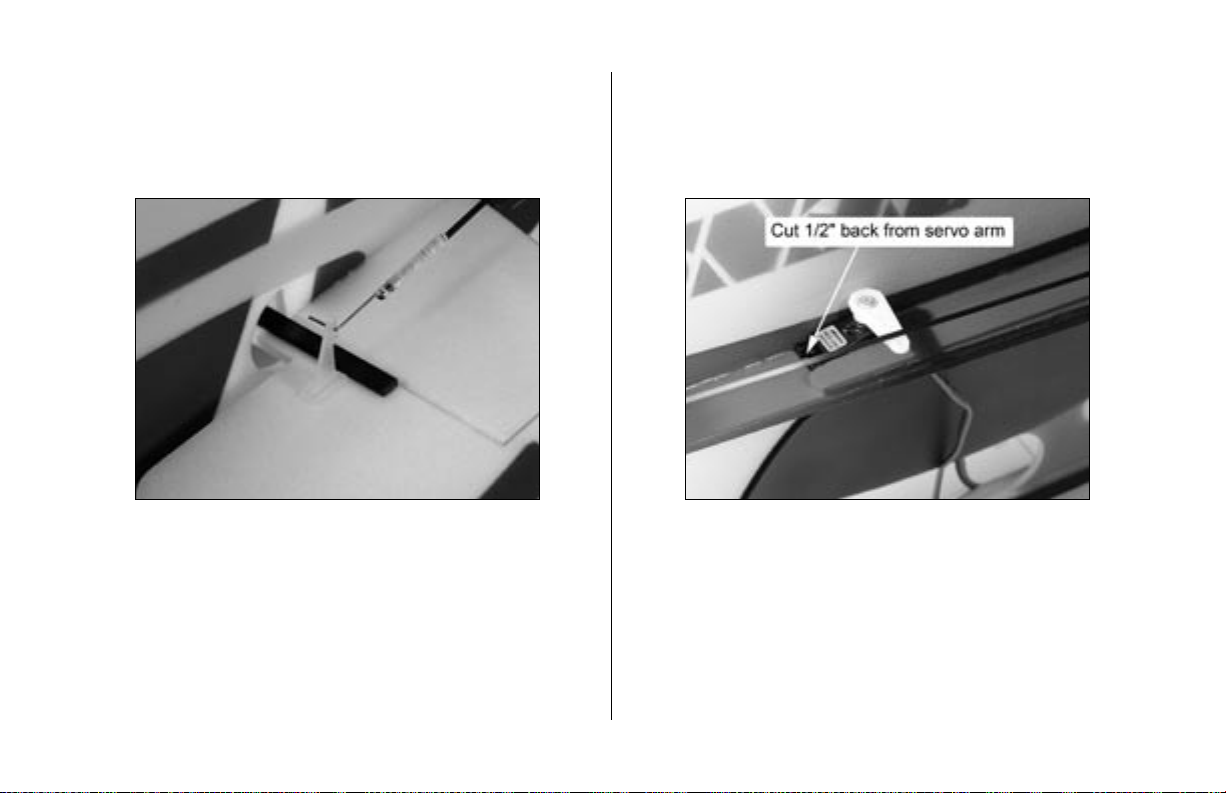
8. Tape the elevator so it will remain centered.
Measure back 1/2" from the elevator servo arm
on the pushrod. Cut the pushrod at this location
using a razor saw.
9. Attach another 1/32" x 2" pushrod end to
the pushrod.
15
Page 16

10. Install a micro control connector and
connector backplate to the servo arm.
11. Attach the L-bend to the control horn using a
micro pushrod keeper.
16
Page 17

12. Slide the pushrod end through the micro
connector. Center the elevator and secure the
pushrod using a 2mm x 4mm screw.
13. Repeat Steps 7 through 13 to assemble and
install the rudder pushrod.
17
Page 18

Wing Installation
Required Parts
Fuselage Assembly Lower wing
Side force generator (2)
Required Tools and Adhesives
Foam-safe CA Hobby knife
Square
1. Test fit the lower wing to the fuselage. The lower
wing has the holes towards the leading edge for
the landing gear wires.
2. Carefully check to make sure the lower wing
is square to the fuselage. Use foam-safe CA to
glue the lower wing to the fuselage.
18
Page 19

3. Locate the side force generators. Use a sharp
hobby knife to remove the upper and lower
fences from the main section.
4. Position the side force generator in the holes
closest to the trailing edge of the bottom wing.
Use a square and foam-safe CA to glue the side
force generator into position.
5. Repeat Steps 3 and 4 for the remaining side
force generator.
19
Page 20

6. Place the top wing onto a flat surface. Position
the side force generators and fuselage onto
the wing. Hold the wing flat while gluing the
fuselage and side force generators to the wing.
Note: It is recommended to use a square to
check the side force generator alignment to the
top wing.
Note: DO NOT glue the upper and lower
fences at this time.
20
Page 21

Carbon Rod Installation
Required Parts
Assembled airframe
.046" x 11
.046" x 6
Required Tools and Adhesives
Foam-safe CA Thin CA
T-Pin
Note: You may want to locate a thin piece
of depron or other foam for the next section.
A thin board will work too. This is necessary
to keep the wing as flat as possible to keep
from inducing any twist in the wing, which will
greatly affect the performance of your Tensor.
1. Use a T-pin to make small holes where the cross
braces will be installed. These locations are
located 3” back on the top and bottom of the
wing supports at the fuselage, and 2” back for
the side force generators.
1
/
” carbon rod (4)
4
1
/
" carbon rod (6)
4
Hint: If you look carefully there are notches at
the locations mentioned in Step 1.
21
Page 22

2. Slide a .046" x 11
1
/
" carbon rod from
4
the lower fuselage to the upper side force
generator. Leave at least 1/16" of the rod
exposed at both ends. Glue only the rod at the
fuselage. Apply foam-safe CA to the rod both
at the inside and outside in order to capture the
rod in position.
3. Place the top wing on a surface that will allow
the wing panel to lie perfectly flat. Apply glue to
the inside edge of the rod. Once the glue fully
cures carefully lift the airframe and apply CA to
the top of the rod.
4. Repeat Steps 2 and 3 for the opposite side.
22
Page 23

5. Slide a .046" x 11
1
/
" carbon rod from
4
the upper fuselage to the lower side force
generator. Leave at least 1/16" of the rod
exposed at both ends. Glue only the rod at the
fuselage. Apply foam-safe CA to the rod both
at the inside and outside in order to capture the
rod in position.
6. Place the bottom wing on a surface that will
allow the wing panel to lie perfectly flat. Apply
glue to the inside edge of the rod. Once the
glue fully cures carefully lift the airframe and
apply CA to the top of the rod.
7. Repeat Steps 5 and 6 to complete the
cross bracing.
23
Page 24

8. Install one of the .046" x 6
1
/
" rods through
4
the hole in the center of the side force generator
and into the fuselage spine. Leave at least
1/16" of the rod exposed on the outside of the
side force generator. Glue the rod only to the
fuselage spine.
Note: There is a small notch in the spine for the
location for the carbon rod.
9. Use a straight edge to make sure the side
force generator is not bent in or out on the
wing. Glue both sides of the rod to the side
force generator.
10. Repeat Steps 8 and 9 for the remaining
center rod.
24
Page 25

11. Locate two .046" x 6
1
/
" carbon rods for use
4
as the tip bracing. Glue the braces at the side
force generator first, and then check the wing
on a flat surface before gluing the brace to the
upper and lower wings. Repeat for both left
and right sides.
12. Cut a 10" piece of string. Wrap the string
around the junction of the inner braces. Use thin
CA to secure the string to the braces.
25
Page 26

Aileron Servo Installation
Required Parts
Assembled airframe
Micro control connector (4)
Control connector backplate (4)
2mm x 4mm screw (4)
Micro control horn (6)
Micro control horn backplate (6)
.065" x 7" carbon pushrod (2)
1/32" x 2" pushrod end (4)
1/32" x 3
Micro pushrod keeper (2)
Required Tools and Adhesives
Foam-safe CA T-Pin
Drill 1/16" drill bit
Razor saw
1
/
" pushrod (2)
8
1. Position the aileron servo on the bottom of the
bottom wing so the output shaft is 4
of the trailing edge. Mark the position of the
front and rear of the servo onto the wing
using a T-pin.
1
/
" forward
2
26
Page 27

2. Cut a hole in the bottom wing and
through the vertical fuselage that will fit your
particular servo. Make sure the hole is
centered in the wing.
3. Install the aileron servo using foam-safe CA.
Make sure to glue the servo to both the wing
and the fuselage.
4. Install the aileron control horns and micro
connectors. Use a servo arm that is the same
width as the spacing between the control horns.
27
Page 28

5. Build and install the linkages using two
1/32" x 3
to the control horn using two micro pushrod
keepers. Center the ailerons and aileron servo.
Use 2mm x 4mm screws to complete the aileron
linkage installation.
1
/
" pushrods. Secure the linkages
8
6. Trim the remaining four control horns as shown.
Enlarge the hole in two (2) of the control horns
using a 1/16" drill bit.
28
Page 29

7. Install the remaining two micro connectors in
the drilled out horns. Make sure to install the
connectors opposite each other as shown.
8. Install a horn from the previous step in the
upper wing. The connector will face outward,
allowing access to the screw. The horn will face
away from the wing as shown.
29
Page 30

9. Install a control horn in the bottom aileron.
10. Assemble an aileron connecting pushrod
using .065" x 7" carbon rod, 1/32" x 2"
pushrod end and 10" of string. Bend the rod at
a 90-degree angle and attach it to the bottom
aileron control horn. With the ailerons centered,
measure and mark the pushrod 1/2" below the
connector on the top aileron.
30
Page 31

11. Cut the carbon at the rod at the mark made
in the previous step using a razor saw. Finish
the assembly of the pushrod using a
1/32" x 2" pushrod end and 10" of string.
Install the pushrod using a micro pushrod
keeper and a 2mm x 4mm screw.
12. Repeat Steps 8 through 11 to assemble
and install the remaining aileron connecting
pushrod.
31
Page 32

Installing the Electronics
Required Parts
Assembled airframe Plywood motor mount
4-40 x 3/8" socket screw (2)
4-40 locknut (2) Hook and loop tape
Required Tools and Adhesives
Foam-safe CA 1/8" drill bit
Drill Receiver
Speed control Motor
1. Locate the plywood motor mount. Attach your
particular motor at this time using two 4-40 x
3/8” socket screws and two 4-40 locknuts. To
save weight use wood screws, making sure they
are secure in the mount by adding a drop of
thin CA when the protrude from the mount.
2. Slide the motor into position in the fuselage.
Glue the plywood mount to the fuselage using
foam-safe CA. Trim the fuselage as necessary to
clear the motor and wiring to the motor.
32
Page 33

3. Mount the receiver in an inconspicuous location
on the fuselage spine using hook and loop or
double-sided tape. Plug the elevator, rudder
and aileron servos into the receiver. Route the
antenna wire to the bottom of the fin.
4. Solder any necessary connectors to your
speed control. Cut a small hole in the fuselage
spine to pass the battery lead through. Connect
the speed control to the receiver and motor.
Attach the speed control to the fuselage spine
using hook and loop or double-sided tape. Tie
any loose wires so there is no chance they can
enter into the spinning propeller.
33
Page 34

5. Use hook and loop tape to secure the battery
directly to the side of the fuselage behind the
motor positioned to obtain the correct CG.
An alternate method is shown below. Trim a
section of the fuselage so you can slide the
battery in place, securing with hook and loop.
6. Set up the operation of the motor using the
instructions included with your particular speed
control at this time.
7. Attach the propeller to the motor, after making
sure the battery has been unplugged.
34
Page 35

Landing Gear Installation
Required Parts
Assembled airframe Landing gear (2)
1
1
/
" wheel (2) Wheel stopper (2)
2
Wheel pant (2)
Required Tools and Adhesives
Foam-safe CA
1. Place the wheels on the landing gear. Check
that they can roll freely. Enlarge the hole in the
wheel if necessary. Use a wheel stopper and
foam-safe CA to retain the wheel.
Note: Be very careful not to get CA onto the
wheel, preventing it from rolling.
2. Slide the gear into position, but do not glue it
yet. The end of the gear will rest in the hole on
the fuselage spine support.
3. Repeat Steps 1 and 2 for the remaining landing
gear and wheel.
35
Page 36

4. Position the wheels so they are parallel to the
fuselage centerline. Check to make sure the
installation of the landing gear is not deforming
the bottom wing. Use foam-safe CA to glue the
landing gear to the wing, vertical fuselage and
horizontal fuselage support.
5. Attach the wheel pants by gluing them to the
wheel stoppers.
36
Page 37

Final Assembly
Required Parts
Assembled airframe
.065" x 6" carbon rod (2)
Upper and lower side force generator (2)
Required Tools and Adhesives
Foam-safe CA
1. Locate a .065" x 6" carbon rod. Position the
rod from the tip of the stabilizer to the bottom
of the fin. Use foam-safe CA to glue the rod
into position.
2. Repeat step 1 for the remaining carbon rod.
3. While the plane is upside down, install
the lower fences onto the bottom wing.
37
Page 38

4. Turn the plane over so it is resting on its wheels.
Install the upper fences using foam-safe CA.
Control Throws
Aileron: 30 degrees Up 30 degrees Down
(Use 40% expo)
Elevator: 60 degrees Up 60 degrees Down
(Use 60% expo)
Rudder: 40 degrees Right 40 degrees Left
(Use 50% expo)
38
Page 39

Center of Gravity
General Set-up Tips for 3D Flight
An important part of preparing the aircraft for
flight is properly balancing the model.
Caution: Do not inadvertently skip this step!
The recommended Center of Gravity (CG)
location for the Tensor™ is 2
1
/
"—2
4
1
/
"
2
(57mm—63.5mm) behind the leading edge of
the top wing against the fuselage. If necessary,
move the battery pack towards the nose or the
tail until the correct balance is achieved.
People often spend a tremendous amount of time
constructing a perfectly straight airplane only to
neglect the radio installation. The control system is
arguably of equal importance to actual construction
and must be given adequate attention to ensure
that the potential of the airplane is realized.
Since the purpose of the Tensor is 3D/Artistic
Aerobatic flying, take a moment to think about
what is actually necessary for successful 3D flight.
The first obvious answer is static thrust. In order to
hover, the minimum amount of thrust necessary is
equal to the total weight of the airplane. In reality
we need to have some excess thrust to maneuver
and accelerate. This is the primary reason that
the total weight of the airplane must be kept to a
minimum. The Tensor is designed to have a flying
weight under 10 ounces. The best way to test to
make sure you have adequate thrust for hovering
39
Page 40

flight is to hold the airplane vertically and advance
the throttle to full power. The static thrust should be
enough to make the airplane accelerate vertically
from a standstill.
Many people also consider the proverbial “aft”
center of gravity (CG) to be crucial to hovering
success. Through much experimentation on many
types of models, we have found that neither a very
forward or very aft CG is beneficial to hovering
flight. In fact, given sufficient control surface
movement, softened correctly with exponential
throws, one can hover controllably over a large
range of CG positions. The center of gravity is even
more critical on the Tensor because it is capable
of producing substantial force (lift) both up-anddown and side-to-side. In other words a single
CG position must provide both longitudinal and
directional stability.
This brings us to the most important aspect of 3D
setup—control surface deflection. Do you need
large amounts of deflection to hover? The truth
is you do not. During the perfect hover or torque
roll you barely move the surfaces off their neutral
position. It is not until you get the airplane in an
attitude far enough from vertical that you need to
delve into your large reserves of control surface
throw and excess power. You will find that having
45–60 degrees of throw is very beneficial to your
success in 3D flight. Typically, the most throw you
can mechanically achieve is what you should use.
Set up the airplane such that maximum throw
is obtained by placing the pushrod the farthest
hole out on the servo and the hole closest to the
control surface on the control horn. While this is
not standard or recommended practice on a larger
airplane because of the potential of flutter, this type
of setup works quite well on the aerobatic indoor
electric models.
40
Page 41

Large amounts of throw tend to make the airplane
feel very sensitive around neutral. Because of this,
it is highly recommended that you use a radio
with dual rates that is capable of exponential
throws. A good way to correctly set the amount
of exponential for the 3D-rate is to find a lowrate setting that feels comfortable in normal flight.
Once you’ve done this for the aileron, elevator,
and rudder, dial in enough exponential to make
the low-rate setting and 3D-rate setting feel the
same for the first 1/3 of the stick travel. If you have
a computer radio that displays the graph of stick
position vs. servo output, you can easily set the
correct amount of exponential by making the slopes
of these graphs identical for the first 1/3 of stick
movement as shown on the following page.
Trimming and Flying the Tensor 4D
Now that the airplane mechanical set-up is correct,
it is time to fine-tune the set-up in the air. Start by
flying the airplane on low rates. If you have triple
rates, set the mid-rate in between the high and low
rates. Once you get comfortable with the airplane
and tune the exponential setting, you will be able
to fly it all the time on the 3D rates.
One will find the propeller effects (such as torque,
spiral slipstream, P-factor, gyroscopic procession
and prop normal force) often dominate the stability
and control of the smaller indoor airplanes.
Consequently, the use of smaller diameter/lowerpitch propellers tends to reduce the adverse effects
on the airplane’s longitudinal and directional
stability. The smaller diameter will reduce static
thrust, however, lower pitch increases static
thrust. With this in mind, we quickly see there
is a compromise between the precision and 3D
propeller selection. Note that the Tensor was
designed to perform well on a 10 x 4.7 propeller.
While most airplanes need right thrust because of
41
Page 42

an asymmetric vertical tail configuration, the Tensor
has nearly equal vertical tail area above and below
the thrustline. As a result the Tensor needs no side
thrust to fly properly.
Rolling maneuvers are done with relative ease
with the Tensor. What you will find is that very
little if any rudder is needed during the knife-edge
portion of the roll to keep the nose from falling. This
is because the side force generators are literally
holding the nose up for you. This makes it easy to
perform normal aileron rolls, slow rolls, point rolls,
rolling circles and rolling loops while using very
little rudder input.
Knife-edge flight is also a strong point of the Tensor.
The side force generators allow it to fly very slowly
in knife-edge. The Tensor does have both roll and
pitch coupling that should be mixed out with a
computer radio. At the center of gravity position
specified in these instructions, the Tensor will tend to
pitch toward the landing gear both in left and right
rudder knife-edge flight. Simply use a linear rudder
to elevator mix to reduce this pitching tendency.
Left and right rudder knife-edges will require
slightly different levels of mixing because of Pfactor. Typically right rudder knife-edge flight
requires less up elevator mix that left rudder knifeedge. The Tensor also has some proverse roll
coupling with rudder. This means that the airplane
will tend to roll in the same direction as the rudder
input. Use a linear rudder to aileron mix to reduce
this rolling tendency. The fences that extend the
side force generators through the wing are in place
to reduce and linearize the Tensor’s roll coupling.
At the bottom of a tight knife-edge loop one will
notice that the coupling will change direction if the
sideslip angle gets too large. This roll reversal is
gradual enough that the pilot can overcome it by
giving aileron in the same direction as rudder. This
little trick makes performing knife edge loops much
easier than trying to use a nonlinear mix to handle
the situation.
42
Page 43

The Tensor is especially good at the 3D type
maneuvers such as Torque Rolls, Elevators /
Harriers, and High-Alpha Rolls. The large amount
of aileron area in the propeller slipstream actually
make it possible to perform anti-torque rolls
(spinning to the right while hovering) Because of
its ultra-light wing loading the Tensor is truly meant
to be flown indoors in a windless environment
but will easily handle 5-10mph wind conditions
outside. The Tensor seems to fly best with a 7.2V
Li-Poly battery indoors and a 12V Li-poly battery
outdoors. Many of the top-level pilots who have
flown this model say that it has new maneuvers
hidden inside it…perhaps you’ll be the one to
discover them.
Basic Guide for Learning to Fly 3D
Maneuvers
The Tensor is quite capable of performing a wide
range of 3D maneuvers, but the ultimate goal is
to make the pilot capable of performing them as
well…let’s start with some thoughts about torque
rolls and hovering in general.
How does one go about learning how to torque
roll? The best way is to practice on a simulator
until you can literally do the maneuver without
needing to think about the inputs. The skill involved
is nothing more than a muscle memory response to
what you see the airplane doing.
Is the simulator realistic? Probably not, but
regardless of its accuracy it will get your eyes
and hands accustomed to the proper movements
required to perform the maneuver. The simulator
will help you get over the “mechanics” of the
maneuver so you will not have to think about which
direction to move the sticks when faced with the
real thing.
43
Page 44

How much should you have to practice? If you are
serious about learning how to hover or torque roll,
work on the simulator 30 minutes to an hour each
night for a month. Evaluate your progress after
this amount of time. Chances are you will have
become bored with the simulator and are ready
to tackle the real airplane with confidence, but do
not be surprised or discouraged if it takes three
months of dedicated practice. Remember that there
is nothing super-human about hovering. Anyone
who is willing to put in the practice time can learn
to do this maneuver. Of course you can be a purest
and learn to hover solely with the real airplane, but
it will take longer because you physically cannot
get the practice time with a model that you can
on the simulator. Keep in mind that your simulator
practice must be supplemented with actual flying
because you need to learn how to react when the
consequence of a mistake is a crash. The good
thing about the Tensor is you can typically pick
it up after a mishap and fly again immediately.
Nerves can play a big part in hovering success,
but you will find the better you get at the simulator,
the more confidence you will have with the real
airplane and the nerves will eventually subside,
thus freeing your mind to concentrate on flying the
model. It often helps to have someone show you
that your airplane can hover. For some reason
this is a huge psychological boost that makes you
realize it is not the airplane limiting you. One
common mistake people make is hovering too
far away from them. The closer you are to the
airplane, the better you will be able to control it
because you can see it so much better. This is,
of course, a double-edged sword because you
will also be closer to the ground. Once again the
Tensor can handle the abuse thus making it good
for training. Eventually you will find that the closer
the airplane is to the ground, the less chance it has
of getting damaged in a crash because it has less
potential energy. This is especially useful if for some
reason you have a battery die or the BEC cuts off.
44
Page 45

Another common misnomer is that the ailerons do
not work while hovering. This could not be further
from the truth. If you do not use the ailerons during
hovering, you will be at the mercy of the motor’s
torque and the airplane will continually roll to the
left. Two very effective techniques to employ to
reduce or stop this rotation is first to counter the
left rolling moment with right aileron and also to
lean the airplane 5–10 degrees either slightly to the
gear or away from it. Leaning the airplane makes
it more difficult for the torque of the motor to roll
the airplane because the weight and thrust vectors
are misaligned. You can also use this mode of flight
to move the airplane closer or further away from
you. When you start doing this, you will quickly
realize that you are starting to perform a very high
angle of attack harrier.
With this in mind let’s tackle the “Elevator” and
“Harrier,” which is the second most popular 3D
maneuver. A common misconception is that you
always fly around with the elevator fully deflected.
What you will find is you must continually modulate
the elevator to maintain the same angle of attack.
This is done by watching the flight path and body
angle of the airplane and adjusting the elevator
and throttle accordingly. Also you must work to
keep the wings level with the ailerons. Many times
we hear people say that certain airplanes do not
lock into the harrier well. While this may be true,
what you will find is most every airplane has a
magic angle of attack that minimizes wing-rock,
and the pilots whose airplanes appear to be locked
into these maneuvers know how to keep their
airplane in this sweet spot.
45
Page 46

2004 Official AMA
National Model Aircraft Safety Code
GENERAL
1) I will not fly my model aircraft in sanctioned events,
air shows or model flying demonstrations until it
has been proven to be airworthy by having been
previously, successfully flight tested.
2) I will not fly my model higher than approximately
400 feet within 3 miles of an airport without notifying
the airport operator. I will give right-of-way and avoid
flying in the proximity of full-scale aircraft. Where
necessary, an observer shall be utilized to supervise
flying to avoid having models fly in the proximity of
full-scale aircraft.
3) Where established, I will abide by the safety rules
for the flying site I use, and I will not willfully or
deliberately fly my models in a careless, reckless and/
or dangerous manner.
4) The maximum takeoff weight of a model is 55
pounds, except models flown under Experimental
Aircraft rules.
5) I will not fly my model unless it is identified with
my name and address or AMA number on or in the
model. (This does not apply to models while being
flown indoors.)
6) I will not operate models with metal-bladed
propellers or with gaseous boosts, in which gases
other than air enter their internal combustion
engine(s); nor will I operate models with extremely
hazardous fuels such as those containing
tetranitromethane or hydrazine.
RADIO CONTROL
1) I will have completed a successful radio equipment
ground range check before the first flight of a new or
repaired model.
2) I will not fly my model aircraft in the presence
of spectators until I become a qualified flier, unless
assisted by an experienced helper.
46
Page 47

3) At all flying sites a straight or curved line(s) must
be established in front of which all flying takes place
with the other side for spectators. Only personnel
involved with flying the aircraft are allowed at or in
front of the flight line. Intentional flying behind the
flight line is prohibited.
4) I will operate my model using only radio control
frequencies currently allowed by the Federal
Communications Commission. (Only properly licensed
Amateurs are authorized to operate equipment on
Amateur Band frequencies.)
5) Flying sites separated by three miles or more
are considered safe from site-to site interference,
even when both sites use the same frequencies. Any
circumstances under three miles separation require a
frequency management arrangement, which may be
either an allocation of specific frequencies for each site
or testing to determine that freedom from interference
exists. Allocation plans or interference test reports
shall be signed by the parties involved and provided
to AMA Headquarters. Documents of agreement and
reports may exist between (1) two or more AMA
Chartered Clubs, (2) AMA clubs and individual AMA
members not associated with AMA Clubs, or (3) two or
more individual AMA members.
6) For Combat, distance between combat engagement
line and spectator line will be 500 feet per cubic inch
of engine displacement. (Example: .40 engine = 200
feet.); electric motors will be based on equivalent
combustion engine size. Additional safety requirements
will be per the RC Combat section of the current
Competition Regulations.
7) At air shows or model flying demonstrations, a
single straight line must be established, one side of
which is for flying, with the other side for spectators.
8) With the exception of events flown under AMA
Competition rules, after launch, except for pilots or
helpers being used, no powered model may be flown
closer than 25 feet to any person.
9) Under no circumstances may a pilot or other person
touch a powered model in flight.
47
Page 48

7184
© 2004 Horizon Hobby, Inc.
4105 Fieldstone Road
Champaign, Illinois 61822
(877) 504-0233
www.horizonhobby.com
 Loading...