

Page 1
T-34 Mentor 25 ePTS
Assembly Manual
Specifications
Wingspan: 55 in (1575mm)
Length: 44 in (1110mm)
Wing Area: 545 sq in 34.9 sq dm)
Weight w/ Battery: 4.4–4.5 lb (1.9–2.0 kg)
Weight w/o Battery: 5.0–5.2 oz (2.2–2.3 kg)
Page 2

Table of Contents
Introduction
Specifications ...................................................................... 1
Introduction ......................................................................... 2
Using the Manual ................................................................ 2
Contents of Kit/Parts Layout ................................................. 3
Required Tools and Adhesives .............................................. 3
Optional Accessories ........................................................... 3
Warranty Information .......................................................... 4
Note on Lithium Polymer Batteries ........................................ 6
Warning ............................................................................. 6
Safety, Precautions, and Warnings ....................................... 6
Wing and Landing Gear Assembly ...................................... 7
Tail Installation ..................................................................10
Battery and Wing Installation ............................................. 13
Centering the Control Surfaces and
Checking Control Direction ...................................... 15
Setting the Control Throws ................................................. 22
General Maintenance ........................................................ 25
Positioning the Flaps .......................................................... 27
Removing the NACA Wing Droops .................................... 28
Operational Flap Installation (Optional) .............................. 29
Center of Gravity .............................................................. 34
Range Test Your Radio ....................................................... 34
Instructions for Disposal of WEEE by
Users in the European Union ................................... 34
Preflight ............................................................................ 35
Li-Po Battery Pack Information ............................................ 35
2008 Official AMA National Model Aircraft Safety Code ... 38
Optional Items for Your T-34 Mentor ................................... 39
For decades, the T-34 has been the airplane in which nearly all
U.S. Navy, Marine, and Coast Guard aviators have earned their
wings of gold. Based upon the civilian Model 35 Bonanza, the
all-metal T-34 has been rugged and reliable, enduring countless
loops, rolls, stalls and hard landings at the hands of student pilots
throughout the years.
And now, E-flite provides you with the most advanced electric
training aircraft in the RC world. ePTS™ stands for Electric
Progressive Trainer System—an airplane that will allow you to go
from training to aerobatics without upgrading or purchasing a
new plane.
This warbird comes ready-to-fly—no building is required and
everything needed to fly is included. The T-34 Mentor sports
removable NACA droops and a progressive 3-position flap
system to provide extra stability and slow flying. Master the
basics, remove the droops, and change flap position to move up
to great sport performance and mild aerobatics.
Progress from student pilot to aerobatic performer with E-flite’s
T-34 Mentor 25 ePTS RTF.
Using the Manual
This manual is divided into sections to help make assembly
easier to understand, and to provide breaks between each major
section. In addition, check boxes have been placed next to each
step to keep track of each step completed. Steps with a single
circle () are performed once, while steps with two circles ( )
indicate that the step will require repeating, such as for a right or
left wing panel, two servos, etc.
Remember to take your time and follow the directions.
2 E-flite T-34 Mentor ARF Assembly Manual
Page 3
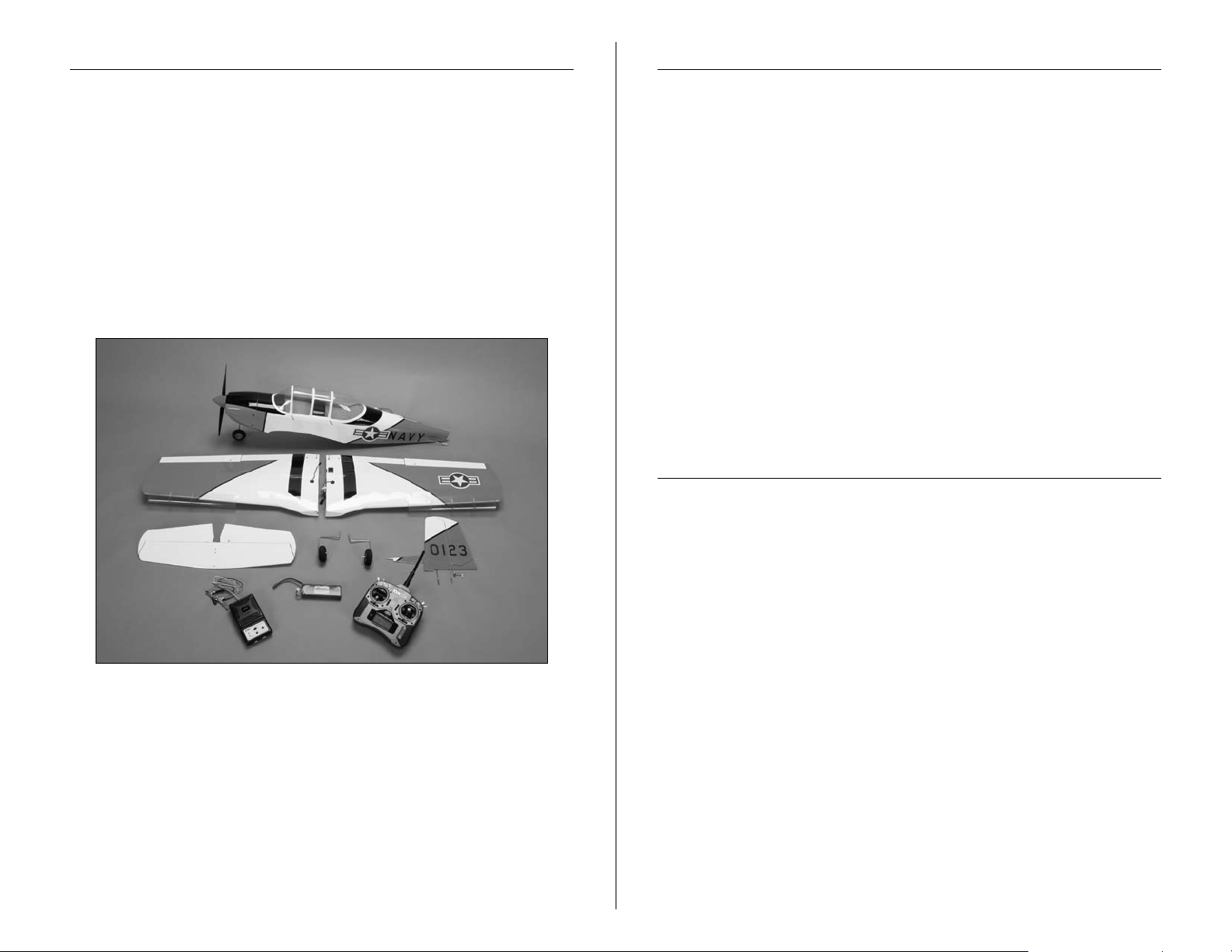
Contents of Kit/Parts Layout
Required Tools and Adhesives
Large Parts:
EFL4801 Wing Set w/Ailerons
EFL4802 Fuselage
EFL4803 Tail Set
EFL4804 Cowling
EFL4805 Fuselage Hatch
EFL4806 Pushrod Set
EFL4807 Landing Gear
EFL4808 Spinner
EFL4809 Tail Cone
EFLP12080E 12x8 Electric Propeller
Tools & Equipment
EFLA250 Park Flyer Tool Assortment, 5-piece
Or Purchase Separately
EFLA257 Screwdriver, #1 and #2 Phillips
(or included with EFLA250)
Covering iron
Adjustable wrench
Pin drill
Drill bit: 1/16-inch (1.5mm), 5/64-inch (2mm)
Flat blade screwdriver
Phillips screwdriver: #1, #2
Medium CA
Threadlock
Hex wrench: 2.5mm
Ruler
Optional Accessories
EFLA110 Power Meter
EFLC3005 Celectra
EFLC505 Intelligent 1- to 5-Cell Balancing Charger
EFLB32003S 3200mAh 3S 11.1V 20C Li-Po Battery
APC12080E 12x8 Elecrtic Prop
JSP20050 ST47 Standard Servo
SPM6805 Trainer Cord
DYN4055 12-Volt, 10-Amp Power Supply
™
1- to 3-Cell Li-Po Charger
3E-flite T-34 Mentor ARF Assembly Manual
Page 4

Warranty Information
Warranty Period
Horizon Hobby, Inc., (Horizon) warranties that the Products purchased
(the “Product”) will be free from defects in materials and workmanship
at the date of purchase by the Purchaser.
Limited Warranty
(a) This warranty is limited to the original Purchaser ("Purchaser") and
is not transferable. REPAIR OR REPLACEMENT AS PROVIDED UNDER
THIS WARRANTY IS THE EXCLUSIVE REMEDY OF THE PURCHASER.
This warranty covers only those Products purchased from an
authorized Horizon dealer. Third party transactions are not covered
by this warranty. Proof of purchase is required for warranty claims.
Further, Horizon reserves the right to change or modify this warranty
without notice and disclaims all other warranties, express or implied.
(b) Limitations- HORIZON MAKES NO WARRANTY OR
REPRESENTATION, EXPRESS OR IMPLIED, ABOUT NONINFRINGEMENT, MERCHANTABILITY OR FITNESS FOR A
PARTICULAR PURPOSE OF THE PRODUCT. THE PURCHASER
ACKNOWLEDGES THAT THEY ALONE HAVE DETERMINED THAT
THE PRODUCT WILL SUITABLY MEET THE REQUIREMENTS OF THE
PURCHASER’S INTENDED USE.
(c) Purchaser Remedy- Horizon's sole obligation hereunder
shall be that Horizon will, at its option, (i) repair or (ii) replace, any
Product determined by Horizon to be defective. In the event of a
defect, these are the Purchaser's exclusive remedies. Horizon reserves
the right to inspect any and all equipment involved in a warranty
claim. Repair or replacement decisions are at the sole discretion of
Horizon. This warranty does not cover cosmetic damage or damage
due to acts of God, accident, misuse, abuse, negligence, commercial
use, or modification of or to any part of the Product. This warranty
does not cover damage due to improper installation, operation,
maintenance, or attempted repair by anyone other than Horizon.
Return of any goods by Purchaser must be approved in writing by
Horizon before shipment.
Damage Limits
HORIZON SHALL NOT BE LIABLE FOR SPECIAL, INDIRECT OR
CONSEQUENTIAL DAMAGES, LOSS OF PROFITS OR PRODUCTION
OR COMMERCIAL LOSS IN ANY WAY CONNECTED WITH THE
PRODUCT, WHETHER SUCH CLAIM IS BASED IN CONTRACT,
WARRANTY, NEGLIGENCE, OR STRICT LIABILITY. Further, in no
event shall the liability of Horizon exceed the individual price of the
Product on which liability is asserted. As Horizon has no control over
use, setup, final assembly, modification or misuse, no liability shall be
assumed nor accepted for any resulting damage or injury. By the act
of use, setup or assembly, the user accepts all resulting liability.
If you as the Purchaser or user are not prepared to accept the liability
associated with the use of this Product, you are advised to return this
Product immediately in new and unused condition to the place of
purchase.
Law: These Terms are governed by Illinois law (without regard to
conflict of law principals).
Safety Precautions
This is a sophisticated hobby Product and not a toy. It must be
operated with caution and common sense and requires some basic
mechanical ability. Failure to operate this Product in a safe and
responsible manner could result in injury or damage to the Product or
other property. This Product is not intended for use by children without
direct adult supervision. The Product manual contains instructions for
safety, operation and maintenance. It is essential to read and follow
all the instructions and warnings in the manual, prior to assembly,
setup or use, in order to operate correctly and avoid damage or
injury.
4 E-flite T-34 Mentor ARF Assembly Manual
Page 5

Questions, Assistance, and Repairs
Non-Warranty Repairs
Your local hobby store and/or place of purchase cannot provide
warranty support or repair. Once assembly, setup or use of the
Product has been started, you must contact Horizon directly. This will
enable Horizon to better answer your questions and service you in the
event that you may need any assistance. For questions or assistance,
please direct your email to productsupport@horizonhobby.com, or call
877.504.0233 toll free to speak to a service technician.
Inspection or Repairs
If this Product needs to be inspected or repaired, please call for a
Return Merchandise Authorization (RMA). Pack the Product securely
using a shipping carton. Please note that original boxes may be
included, but are not designed to withstand the rigors of shipping
without additional protection. Ship via a carrier that provides tracking
and insurance for lost or damaged parcels, as Horizon is not
responsible for merchandise until it arrives and is accepted
at our facility. A Service Repair Request is available at www.
horizonhobby.com on the “Support” tab. If you do not have internet
access, please include a letter with your complete name, street
address, email address and phone number where you can be reached
during business days, your RMA number, a list of the included items,
method of payment for any non-warranty expenses and a brief
summary of the problem. Your original sales receipt must also be
included for warranty consideration. Be sure your name, address, and
RMA number are clearly written on the outside of the shipping carton.
Should your repair not be covered by warranty the repair
will be completed and payment will be required without
notification or estimate of the expense unless the expense
exceeds 50% of the retail purchase cost.
item for repair you are agreeing to payment of the repair without
notification. Repair estimates are available upon request. You must
include this request with your repair. Non-warranty repair estimates
will be billed a minimum of ½ hour of labor. In addition you will be
billed for return freight. Please advise us of your preferred method
of payment. Horizon accepts money orders and cashiers checks, as
well as Visa, MasterCard, American Express, and Discover cards.
If you choose to pay by credit card, please include your credit card
number and expiration date. Any repair left unpaid or unclaimed
after 90 days will be considered abandoned and will be disposed of
accordingly.
Please note: non-warranty repair is only available
By submitting the
on electronics and model engines.
Electronics and engines requiring inspection or repair should be
shipped to the following address:
Horizon Service Center
4105 Fieldstone Road
Champaign, Illinois 61822
All other Products requiring warranty inspection or repair should be
shipped to the following address:
Warranty Inspection and Repairs
To receive warranty service, you must include your original
sales receipt verifying the proof-of-purchase date. Provided warranty
conditions have been met, your Product will be repaired or replaced
free of charge. Repair or replacement decisions are at the sole
discretion of Horizon Hobby.
Horizon Product Support
4105 Fieldstone Road
Champaign, Illinois 61822
Please call 877-504-0233 with any questions or concerns
regarding this product or warranty.
5E-flite T-34 Mentor ARF Assembly Manual
Page 6

Note on Lithium Polymer Batteries
Safety, Precautions, and Warnings
Lithium Polymer batteries are significantly more
volatile than alkaline or Ni-Cd/Ni-MH batteries used
in RC applications. All manufacturer’s instructions
and warnings must be followed closely. Mishandling
of Li-Po batteries can result in fire. Always follow the
manufacturer’s instructions when disposing of Lithium
Polymer batteries.
Warning
An RC aircraft is not a toy! If misused, it can cause serious bodily
harm and damage to property. Fly only in open areas, preferably
at AMA (Academy of Model Aeronautics) approved flying sites,
following all instructions included with your radio.
Keep loose items that can get entangled in the propeller away
from the prop, including loose clothing, or other objects such as
pencils and screwdrivers. Especially keep your hands away from
the propeller.
As the user of this product, you are solely responsible for
operating it in a manner that does not endanger yourself
and others or result in damage to the product or the property
of others.
Carefully follow the directions and warnings for this and any
optional support equipment (chargers, rechargeable battery
packs, etc.) that you use.
This model is controlled by a radio signal that is subject to
interference from many sources outside your control. This
interference can cause momentary loss of control so it is
necessary to always keep a safe distance in all directions around
your model, as this margin will help to avoid collisions or injury.
• Always operate your model in an open area away from cars,
traffic, or people.
• Avoid operating your model in the street where injury or
damage can occur.
• Never operate the model out into the street or populated areas
for any reason.
• Never operate your model with low transmitter batteries.
• Carefully follow the directions and warnings for this and any
optional support equipment (chargers, rechargeable battery
packs, etc.) that you use.
• Keep all chemicals, small parts and anything electrical out of
the reach of children.
• Moisture causes damage to electronics. Avoid water exposure
to all equipment not specifically designed and protected for this
purpose.
6 E-flite T-34 Mentor ARF Assembly Manual
Page 7
Wing and Landing Gear Assembly
Required Parts
Wing panel (left and right) Landing gear strap (5)
Flap linkage (fixed flap) Wing tube
Aluminum anti-rotation pin
3mm x 10mm sheet metal screw (10)
Required Tools and Adhesives
Medium CA Phillips screwdriver: #2
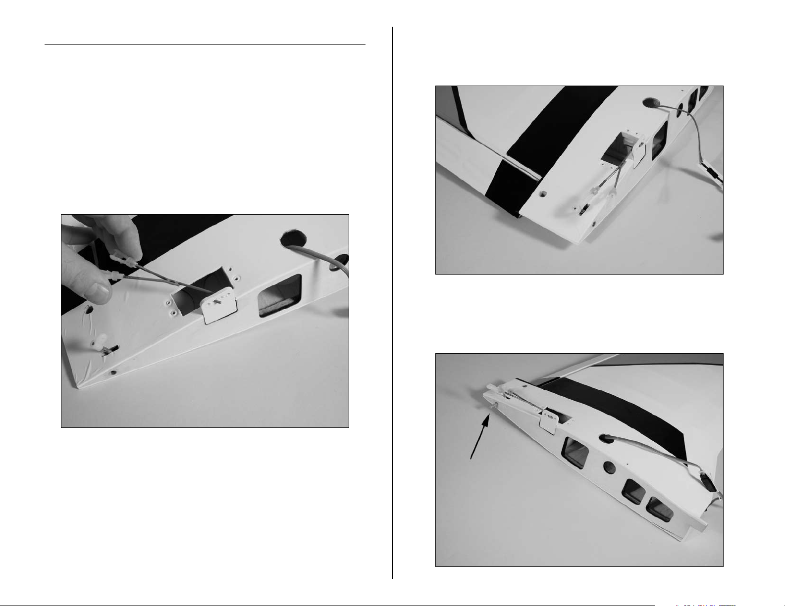
1. Attach the flap linkage to the flap linkage stay. The
linkage will attach to the third hole.
2. Connect the clevis to the flap control horn. You will
note the flap is driven down when you connect the clevis.
We will adjust this position in a few steps.
3. Slice the aluminum anti-rotation pin into the wing. It is
suggested to use medium CA to glue the pin in place to
prevent it from falling out and getting lost.
Note: The flap will be set to the training position in this
section. Setting the flap position for your particular level
of flight skills will be covered later in the manual.
Hint: You can skip steps 1 and 2 if you plan on installing
a servo for the operational flaps. Follow the steps in the
section "Operational Flap Installation (Optional)" instead.
7E-flite T-34 Mentor ARF Assembly Manual
Page 8
4. Slide the wing tube into the wing panel at this time.
5. Attach the landing gear to the bottom of the wing
using two landing gear straps, four 3mm x 10mm sheet
metal screws and a #2 Phillips screwdriver. Attach both
main gears at this time.
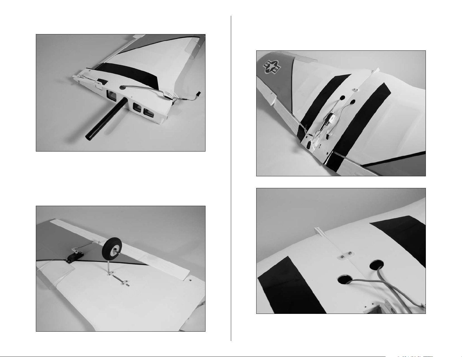
6. Slide the two wing panels tightly together. Once
together install the wing securing strap with two screws
using a #2 Phillips screwdriver.
8 E-flite T-34 Mentor ARF Assembly Manual
Page 9
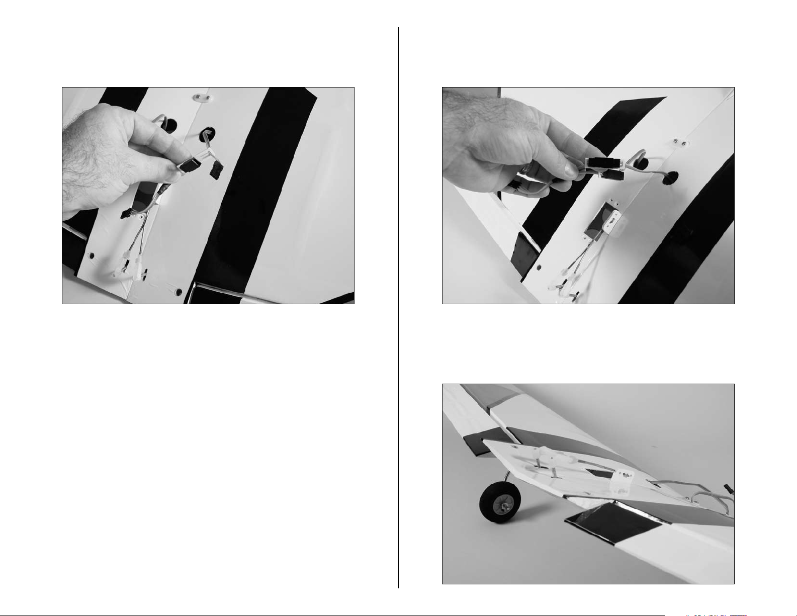
7. Slide the lead from the wing panel through the
connector stay as shown. The stay will prevent the lead
from being unplugged accidentally.
8. Rotate the lead in the stay so the colors align
with those of the lead already installed. Plug the two
connectors together and slide them tight against the stay.
9. Connect the flap linkage to the flap control horn. We
will adjust the flaps to their correct setting later on in the
manual in the "Positioning the Flaps" section on page 27.
9E-flite T-34 Mentor ARF Assembly Manual
Page 10
Tail Installation
Required Parts
Fuselage assembly Stabilizer/elevator
Fin/rudder 3mm washer (2)
3mm locknut (2) 2mm x 8mm sheet metal screw (2)
Tail cone
Required Tools and Adhesives
Phillips screwdriver: #1, #2 Adjustable wrench
Threadlock
1. Slide the stabilizer/elevator into the slot at the rear of
the fuselage. Make sure the control horn faces the bottom
of the fuselage. Align the holes in the stabilizer with the
holes in the fuselage. Connect the elevator pushrod to the
elevator control horn.
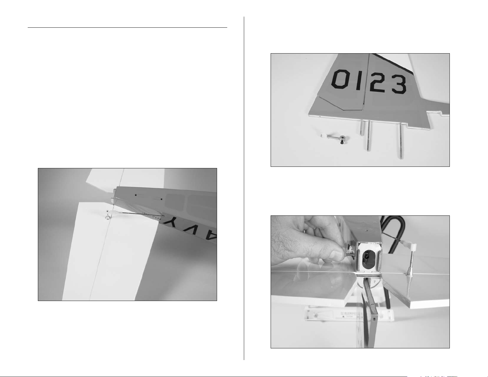
2. Use a #2 Phillips screwdriver to remove the rudder
control horn. You will need to loosen both the short black
screw and control horn screw to remove the control horn.
3. Slide the rudder partially into the fuselage. Install the
control horn so the black screw faces the rear of the
fuselage.
10 E-flite T-34 Mentor ARF Assembly Manual
Page 11
4. Slide the fin fully into position. Use two 3mm washers
and two 3mm locknuts to secure the fin. Tighten these
nuts down using an adjustable wrench.
5. Align the control horn so it is 90 degrees to the rudder
as shown.
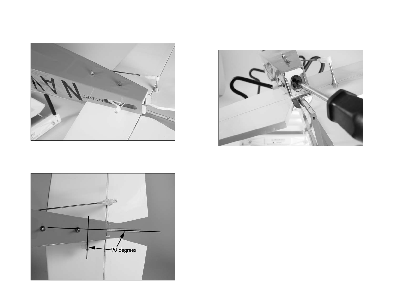
6. Center the control horn vertically in the slot on the side
of the fuselage. Use a #2 Phillips screwdriver to tighten
the black screw against the rudder control rod. Use
threadlock on the screw to prevent it from vibrating loose.
11E-flite T-34 Mentor ARF Assembly Manual
Page 12
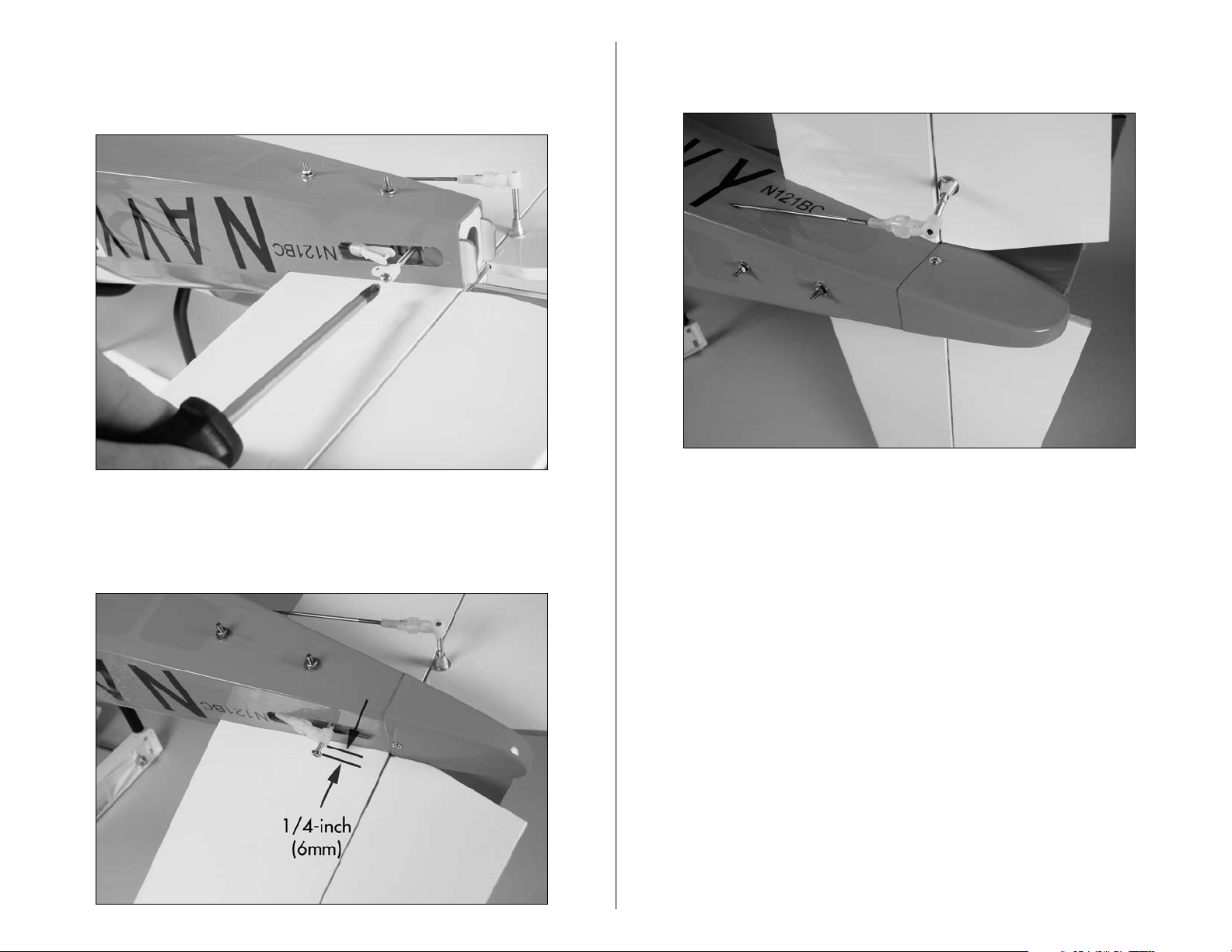
7. Use a #2 Phillips screwdriver to tighten the control
horn screw. Again, the use of threadlock is necessary to
prevent the screw from vibrating loose.
9. Attach the tail cone to the fuselage using two 2mm x
8mm sheet metal screws and a #1 Phillips screwdriver.
8. Screw the nylon control horn in 1/4-inch (6mm).
Connect the clevis from the rudder pushrod to the rudder
control horn.
12 E-flite T-34 Mentor ARF Assembly Manual
Page 13
Battery and Wing Installation
Required Parts
Fuselage assembly Wing assembly
Motor battery Nylon wing bolt (2)
Required Tools and Adhesives
Flat screwdriver: 1/4-inch
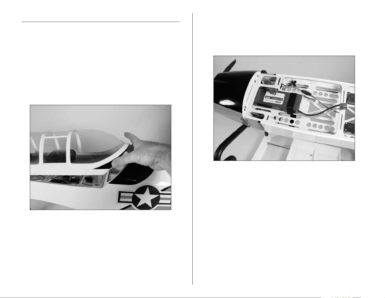
1. Remove the canopy from the fuselage by grasping the
canopy at the aft edge and rocking it left to right. This
will disengage the magnets that hold it in place. The front
has two pins that key into the fuselage.
2. Use the hook and loop straps to secure the motor
battery in the fuselage. The position of the battery
can be adjusted inside the fuselage to correctly balance
the aircraft. For your initial flights, position the battery as
far forward in the fuselage as possible.
13E-flite T-34 Mentor ARF Assembly Manual
Page 14
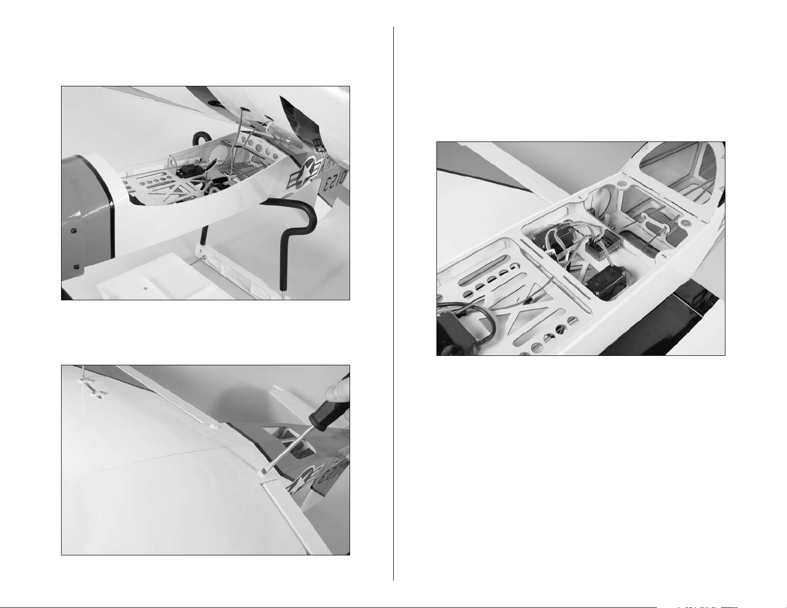
3. Pass the leads for the ailerons (and flap) through the
cross bracing in the fuselage. Guide the tab at the front
of the wing into the slot in the fuselage.
5. Plug the aileron lead into the receiver in the slot
marked AILE. (The flap servo is plugged into the AUX1
slot of the receiver when the optional flaps have been
installed.) Replace the canopy back onto the fuselage.
You will want to make sure you have the wires pressed
down flat and to the side of the receiver before installing
the top hatch.
4. Use two nylon wing bolts and a flat screwdriver to
secure the wing to the fuselage.
14 E-flite T-34 Mentor ARF Assembly Manual
Page 15

Centering the Control Surfaces and
Checking Control Direction
Required Parts
Assembled airframe Motor battery
Radio system
Required Tools and Adhesives
AA battery (4)
Note: This section is designed to help you become
acquainted with the operation of the radio in correlation
to the model. If a flight control moves in the incorrect
direction we will instruct you how to change it in the next
section. ,
1. Follow the radio instructions to install the four AA
batteries.
2. Turn the radio on and check that the sticks and trims
have been centered. The transmitter should display
"T-34EPTS" on the screen.
15E-flite T-34 Mentor ARF Assembly Manual
Page 16

3. Plug the motor battery into the speed control.
Set the throttle stick to low throttle and turn on the
speed control. You will hear a series of beeps or tones
when you plug the battery in. During this process it is
normal for the prop to pulse slightly as the ESC powers
up. Please ensure you are not in line with the prop or in
front of it during power up.
4. Your transmitter should still be on and the battery
plugged in. Now turn the switch on inside the model. The
radio in the model should link up within 10 seconds. If it
does not, turn the switch off and the transmitter off. Then
turn the transmitter on and the switch inside the model on
again and see if the radio links up. If the radio does not
link up at this time, you will need to rebind the system.
This is accomplished in the radio manual that is included
with your system.
Important: Always use extreme caution around the
propeller when the motor battery is plugged in. A
spinning propeller can cause serious damage or injury.
It is always best to stay behind the propeller and keep
it away from loose objects when the battery and speed
control are connected.
16 E-flite T-34 Mentor ARF Assembly Manual
Page 17

Note: The following steps will ensure your flight
controls are centered for the first flight. In the
instructional DVD included with your T-34, we have
shown you how to adjust the clevises and also servo
arms if necessary. Use both of these instructions to
accomplish the following steps.
Checking the Elevator
5. Center the elevator stick and trim. Thread the clevis
in or out on the elevator pushrod until the elevator is
aligned with the stabilizer as shown.
6. Check the movement of the elevator with the radio
system. Pulling the elevator/aileron stick (right stick on
the transmitter) back will make the airplane elevator
move up.
17E-flite T-34 Mentor ARF Assembly Manual
Page 18

7. Check the movement of the elevator with the radio
system. Pushing the elevator/aileron stick forward will
make the airplane elevator move down.
Checking the Rudder
8. Center the rudder stick and trim. Thread the clevis in
or out on the rudder pushrod until the rudder is aligned
with the fin as shown.
18 E-flite T-34 Mentor ARF Assembly Manual
Page 19

9. Check the movement of the rudder using the
transmitter. When the rudder/throttle stick (left side of the
transmitter) is moved right, the rudder should also move
right.
10. Check the movement of the rudder using the
transmitter. When the left stick is moved left, the
rudder should also move left.
19E-flite T-34 Mentor ARF Assembly Manual
Page 20

Checking the Ailerons
11. Center the aileron stick and trim. Thread the clevis
in or out on the aileron pushrod until the ailerons are
aligned with the wing as shown.
12. Check the movement of the aileron using the
transmitter. When the elevator/aileron stick is moved
right, the right aileron will move up and the left aileron
will move down.
20 E-flite T-34 Mentor ARF Assembly Manual
Page 21

13. Check the movement of the aileron using the
transmitter. When the aileron/elevator stick is moved left,
the left aileron will move up and the right aileron will
move down.
Reversing Direction of Flight Controls
If you find any of the control surfaces moving in the opposite
direction (example shown below), you will need to use the Servo
Reversing feature of your radio system. Follow the instructions
for the radio to enter the programming and change the servo
reversing of the offending control surface.
21E-flite T-34 Mentor ARF Assembly Manual
Page 22

Setting the Control Throws
Required Parts
Assembled airframe Motor battery
Radio system
Required Tools and Adhesives
Ruler
Your transmitter and model come out of the box set up and ready
to fly. Should you need to replace your fuselage or wing due to
a mishap or such, this section will help you reset your control
throws to the factory settings.
Note: Measurements are taken at the widest point on
the surface.
These are general guidelines measured from our own flight tests.
You can experiment with different rates to match your preferred
style of flying.
1. Turn the radio on and check that the sticks and trims
have been centered.
2. Plug the motor battery into the speed control.
Set the throttle stick to low throttle and turn on the
speed control.
Important: Always use extreme caution around the
propeller when the motor battery is plugged in. A
spinning propeller can cause serious damage or injury.
It is always best to stay behind the propeller and keep
it away from loose objects when the battery and speed
control are connected.
22 E-flite T-34 Mentor ARF Assembly Manual
Page 23

Elevator Throw
3/8-inch (9.5mm)
Low Rate
3/8-inch (9.5mm)
Low Rate
3/4-inch (19mm)
High Rate
3/4-inch (19mm)
High Rate
3/4-inch (19mm)
High and Low Rate
3/4-inch (19mm)
High and Low Rate
Rudder Throw
3. Use a ruler to check the amount of throw for the
elevator. Move the elevator stick fully and check the
measurements. Adjust the radio as necessary following
the instructions provided with the radio to achieve the
following measurements.
Low Rate: 3/8-inch (9.5mm) (Up/Down)
High Rate: 3/4-inch (19mm) (Up/Down)
4. Use a ruler to check the amount of throw for the
rudder. Move the rudder stick fully and check the
measurements. Adjust the radio as necessary following
the instructions provided with the radio to achieve the
following measurements.
Low Rate: 3/4-inch (19mm) (Right/Left)
High Rate: 3/4-inch (19mm) (Right/Left)
23E-flite T-34 Mentor ARF Assembly Manual
Page 24

Aileron Throw
1/4-inch (6mm)
Low Rate
1/4-inch (6mm)
Low Rate
1/2-inch (13mm)
High Rate
1/2-inch (13mm)
High Rate
5. Use a ruler to check the amount of throw for the
ailerons. Move the aileron stick fully and check the
measurements. Adjust the radio as necessary following
the instructions provided with the radio to achieve the
following measurements.
Low Rate: 1/4-inch (6mm) (Up/Down)
6. Once all the control throws have been set, make sure
to slide the clevis retainers over the clevises to prevent
them from opening accidentally.
High Rate: 1/2-inch (13mm) (Up/Down)
24 E-flite T-34 Mentor ARF Assembly Manual
Page 25

General Maintenance
Required Parts
Fuselage
Required Tools and Adhesives
Phillips screwdriver: #1 Hex wrench: 2.5mm
1. Use a #1 Phillips screwdriver to remove the two screws
that secure the spinner cone to the spinner backplate.
2. Check that the propeller adapter is tight using
a hex wrench or screwdriver that fits into the hole
in the adapter. You will turn this nut counterclockwise to
loosen or clockwise to tighten.
3. To check that the motor is secure to the firewall, you
will first need to remove the spinner. Use a 2.5mm hex
wrench to remove the four screws that secure the cowling
to the fuselage.
25E-flite T-34 Mentor ARF Assembly Manual
Page 26

4. Use the same 2.5mm hex wrench to check the four
screws that secure the motor to the firewall. Once the
motor screws are tight, reverse the previous steps to
install the cowling, propeller and spinner.
5. If your aircraft does not track straight during taxi,
use the screw at the rudder servo and a #1 Phillips
screwdriver to correct the trim. Do not use the radio trim
for ground tracking. The rudder trim at the radio is only
used to trim the rudder in flight.
26 E-flite T-34 Mentor ARF Assembly Manual
Page 27

Positioning the Flaps
Intermediate Setting
Required Parts
Wing assembly
Initial Training Flap Settings
1. Setting the linkage to the third hole back from the
front of the stay sets the flaps to the position for initial
flight training. This will allow the plane to fly at its slowest
speed and will be slowest during landing as well. The
setting for the flaps in this position is 1/2-inch (13mm)
when measured from the trailing edge of the wing to the
trailing edge of the flap.
2. As you continue to advance, the flap linkage can
again be moved forward one hole. The measurement
for the flaps in this setting is 1/4-inch (6mm) from the
trailing edge of the wing to the trailing edge of the flaps.
As described in Step 1, this will allow the aircraft to
fly slightly faster, but will also require a slightly faster
landing speed.
27E-flite T-34 Mentor ARF Assembly Manual
Page 28

Advanced Setting
Removing the NACA Wing Droops
3. Setting the linkage in the forward hole will place the
flap in the full "UP" position. This is the preferred position
for those with flight experience, as the plane will fly more
like a sport aircraft and will require the greatest amount
of skill (for this type of aircraft) during landing.
Required Parts
Wing panel (left and right)
1. Carefully remove the tape from the wing on both the
top and bottom of the wing droop.
28 E-flite T-34 Mentor ARF Assembly Manual
Page 29

2. Once the wing droop has been removed, use a
cleaner to remove the tape residue from the wing.
Note: Check your particular cleaner in an inconspicuous
place before applying it to the wing. If your cleaner is
not compatible with the covering of your aircraft and
damages the covering, it will be in a place that cannot
be seen.
Operational Flap Installation (Optional)
Required Parts
Wing panel (left and right) Flap servo w/hardware
Flap linkage (operational flap)
Required Tools and Adhesives
Phillips screwdriver: #1 Pin drill
Thin CA
Drill bit: 1/16-inch (1.5mm), 5/64-inch (2mm)
1. Carefully remove the flap stay from the wing panel
as shown.
29E-flite T-34 Mentor ARF Assembly Manual
Page 30

2. Position the flap servo in the wing. Use a felt-tipped
pen to mark the locations for the four servo mounting
screws.
4. Apply a few drops of thin CA into each hole. This will
harden the surrounding wood, making the screws more
secure when they are installed.
3. Use a pin drill and 1/16-inch (1.5mm) drill bit to drill
the four holes in the wing to mount the flap servo.
30 E-flite T-34 Mentor ARF Assembly Manual
Page 31

5. Install the flap servo in the wing using hardware
provided with the servo. The lead from the servo will
pass through the wing and out of the same hole the
aileron lead exits.
6. Use the radio system to center the flap servo. Install
the servo arm so it is perpendicular to the servo. You will
want equal throw in both directions from this position to
operate the flaps.
7. Use a pin drill and 5/64-inch (2mm) drill bit to
enlarge the outer hole of the servo arm.
8. Slide the flap linkage into the hole as shown.
31E-flite T-34 Mentor ARF Assembly Manual
Page 32

9. Slide the linkage connector on the wire, then rotate it
so it snaps on the wire.
10. Use the radio to move the flap servo to the "UP"
position. The servo arm will face toward the leading edge
of the wing. Connect the clevis to the flap control horn.
Check that the flap is aligned with the wing. If not, thread
the clevis in or out until the flap is aligned with the wing.
32 E-flite T-34 Mentor ARF Assembly Manual
Page 33

11. Slide the wing panels together. Connect the linkage
to the remaining flap control horn and adjust the linkage
to set the neutral position for the remaining flap. Secure
the wing panels together as outlined in the first section
of the manual; Wing and Landing Gear Installation
beginning on page 7.
12. Use the radio system to set the position for the flap.
It may be necessary to use the radio system to change
the amount of throw electronically to match those in the
following images. Your goal here is to mimic the flap
settings from the previous section.
33E-flite T-34 Mentor ARF Assembly Manual
Page 34

Center of Gravity
Range Test Your Radio
An important part of preparing the aircraft for flight is properly
balancing the model.
Caution: Do not inadvertently skip this step!
The recommended Center of Gravity (CG) location for the
T-34 Mentor ARF is 4
3
/
– 4
4
7
/
-inch (120–124mm) back from
8
the leading edge of the wing. Mark the location of the CG on
the top of the wing.
Please balance your model while it is inverted with the
battery installed. With the model inverted, lift the model at
the marks using your fingertips, or use a commercially available
balancing stand. The model will rest level or slightly nose down
when balanced correctly. Adjust the position of the motor battery,
or add weight to the nose or tail if necessary to achieve the
correct CG. Please understand that if you use a different Li-Po
battery than the one included, you need to rebalance the model
to verify the Center of Gravity.
1. Please consult your radio instructions for complete
range testing instructions.
2. Double-check that all controls (aileron, elevator, rudder
and throttle) move in the correct direction.
3. Be sure that your transmitter batteries are fully
charged, per the instructions included with your radio.
Instructions for Disposal of WEEE by
Users in the European Union
This product must not be disposed of with other waste. Instead, it
is the user’s responsibility to dispose of their waste equipment by
handing it over to a designated collection point for the recycling
of waste electrical and electronic equipment. The separate
collection and recycling of your waste equipment at the time of
disposal will help to conserve natural resources and ensure that
it is recycled in a manner that protects human health and the
environment. For more information about where you can drop
off your waste equipment for recycling, please contact your local
city office, your household waste disposal service or where you
purchased the product.
After the first flights, the CG position can be adjusted for your
personal preference.
34 E-flite T-34 Mentor ARF Assembly Manual
Page 35

Preflight
Flying the T-34 Mentor
Check Your Radio
Before going to the field, be sure that your batteries are fully
charged per the instructions included with your radio. Charge
both the transmitter and receiver pack for your airplane. Use the
recommended charger supplied with your particular radio system,
following the instructions provided with the radio. In most cases,
the radio should be charged the night before going out flying.
Before each flying session, be sure to range check your radio.
See your radio manual for the recommended range and
instructions for your radio system. Each radio manufacturer
specifies different procedures for their radio systems. Next, start
the motor. With the model securely anchored, check the range
again. The range test should not be significantly affected. If it is,
don’t attempt to fly! Have your radio equipment checked out by
the manufacturer.
Note: Keep loose items that can get entangled in
the propeller away from the prop. These include
loose clothing, or other objects such as pencils and
screwdrivers. Especially keep your hands away from the
propeller.
It is recommended for your first flights to search out the assistance
of a qualified instructor, who will help you through your first
flights and assist you in the basics of Radio Controlled flight. You
can find this guidance at your local hobby dealer’s store. Your
T-34 is capable of flying in winds up to 20 mph but, for flight
training, it is recommended to fly in the lightest wind possible.
You will need to ensure your battery is fully charged and the
model is set up accordingly for your first flight. Do not attempt to
fly the model on a partially charged battery.
The Initial Training Flap Setting is set up for slow gentle flight
with very easy landing characteristics. This setting uses the flaps
in their full down position (as shown on page 27 of the manual)
with the NACA droops installed on the wings. The NACA droops
come pre-installed for you out of the box. This setting is used
for initial flight training as well as initial landing training. In
this configuration, the model will not drop a wing during flight
or landing approach. You will notice a slight amount of down
elevator trim required for level flight due to the flap position. Use
this setting for your first flights and first landing approaches.
Double-check that all controls (aileron, elevator, rudder and
throttle) move in the correct direction.
Check the radio installation and make sure all the control
surfaces are moving correctly (i.e. the correct direction and with
the recommended throws). Test run the motor and make sure
it transitions smoothly from off to full throttle and back. Also
ensure the engine is installed according to the manufacturer’s
instructions, and it will operate consistently.
Check all the control horns, servo horns, and clevises to make
sure they are secure and in good condition. Replace any items
that would be considered questionable. Failure of any of these
components in flight would mean the loss of your aircraft.
35E-flite T-34 Mentor ARF Assembly Manual
Page 36

The Intermediate Flap Setting is set up for gentle flight with easy
landing characteristics. This setting uses the flaps in their half
down position and the NACA droops installed. In this setting,
you will notice a slightly faster landing speed and still very gentle
flight characteristics. A very slight amount of down elevator trim
is required for level flight due to the flap position. Use this setting
for flight once you have mastered the basic flight parameters. For
some, it may be possible to use this setting for your first landing
approaches.
The Advanced Flap Setting is set up for your final training flights.
With the flaps all the way up and the NACA droops still installed,
you will find the stall characteristics of the model continue to
be very benign, but the model will be faster in flight and more
maneuverable. Landings will be a bit faster but still very easily
accomplished with the stability of the T-34. You will find the basic
flight maneuvers of loops and rolls are easily accomplished with
the model in the Advanced Flap Setting mode.
36 E-flite T-34 Mentor ARF Assembly Manual
Page 37

The final setting is to remove the NACA droops. With these
removed, you will find the T-34 very lively in its flight abilities
while maintaining a very docile flight profile. Stalls in this
configuration will routinely fall straight ahead and recover
almost instantly. Inverted flight, loops, and rolls all are easily
accomplished while maintaining the model’s quality scale
appearance.
Li-Po Battery Pack Information
Warning!
Lithium Polymer (Li-Po) batteries are significantly more volatile
than other rechargeable batteries used in RC applications. Failure
to read and follow these instructions and safety precautions may
result in fire, personal injury and damage to property. E-flite,
Horizon Hobby, Inc., its retailers, and any other representatives,
assume absolutely no liability for use of this product or failure to
comply with these instructions and precautions.
If you are not prepared to accept complete liability for the
purchase and/or use of this product, you are advised to return
it new and unused to the place of purchase immediately.
Never ship batteries without the expressed permission of the
recipient. Batteries carrying 25% or more charge cannot be
shipped safely. Batteries which are damaged cannot be shipped
safely. Damage or loss due to unsafe shipping is the legal
responsibility of the person who shipped the product.
We hope you enjoy the T-34 as much as we have. We are
confident you will enjoy many flights with your T-34. Happy
landings.
CAUTION: This product may ignite under certain
conditions. Please read all safety precautions before use.
Please call 877-504-0233 with any questions or concerns
regarding this product or warranty.
37E-flite T-34 Mentor ARF Assembly Manual
Page 38

Usage Guidelines, Warnings and Safety Precautions
• Li-Pobatteriesmayexplodeifdamagedorifdisposed
of improperly.
• Lithium batteries can still ignite after at least 45 minutes
due to a delayed chemical reaction. If battery is damaged or
overheats, observe the battery in a safe area outside of any
building or vehicle and away from combustible material.
• Alwaysinspectbatteriesbeforecharging.
• Never charge or use a Li-Po battery or pack that shows
any damage or disfigurement of any kind. Swelling is a
sign of internal damage. Any breach of protective cover,
wiring or plugs is also reason to discontinue use (See
Disposal Instructions).
• Use specific Lithium Polymer charger only. Do not use a Ni-Cd
or Ni-MH charger – failure to do so may cause a fire, which
may result in personal injury and/or property damage.
• Never charge around or in the area of any flammable or
combustible materials.
• Always charge Li-Po batteries in or on fire resistant materials
or containers.
• Never leave battery and charger unattended while in use.
Improper charging or discharging of Li-Po batteries could
result in fire.
• Constantly monitor the temperature of the battery pack while
charging. If the battery becomes hot to the touch discontinue
charging immediately. Disconnect the battery from the charger
and observe it in a safe place for at least 15 minutes.
• If at any time you see a battery starting to balloon or swell up,
discontinue charging or using immediately.
• DonotallowchildrentochargeLi-Pobatterypacks.
• DonotallowchildrentouseLi-Pobatterieswithout
adult supervision.
• Shorting the wire leads can cause fire. If you accidentally
short the wires, the battery must be placed in a safe area for
observation for at least 15 minutes.
• Never store or charge a battery pack where the temperature
will go below 32 degrees Fahrenheit or above 130 degrees
Fahrenheit. Extreme temperatures will damage the battery pack
and may cause a fire. Battery performance may be diminished
by less extreme temperatures.
• Any of the following may cause the battery to be damaged
resulting in battery swelling, leaking, or fire:
• Bending, folding or dropping of the battery
• Damaging the edge seal of the battery
• Taking apart the battery
• Mixing cells of differing chemistry, or types, or sizes
• Mixing cells of different ages
Crash Damage
If there are signs of smoke or overheating, DO NOT go
near the battery or equipment until it has been observed from
a safe distance for at least 15 minutes. Once it is safe, remove
the battery and check for damage. Dispose of damaged
batteries appropriately.
38 E-flite T-34 Mentor ARF Assembly Manual
Page 39

Swollen Batteries
Basic Disposal Instructions
Immediately stop using or charging. If the battery is not warm
to the touch, move it to an open safe area and observe it for at
least 15 minutes. Be VERY CAREFUL when moving the batteries.
Do NOT put ANY pressure on the batteries or covering as this
may cause fire.
Additional Information & Guidelines
1. Battery temperature the best indicator for safety. The E-flite Li-Po
Battery’s temperature should never drop below 32 degrees
Fahrenheit or go above 130 degrees Fahrenheit while charging
or discharging.
2. Changing plugs is NOT recommended as the process is
dangerous and any error can cause immediate fire. Improperly
installed plugs can also cause fire due to shorts, reverse polarity
or other improper handling which can cause battery damage.
3. Batteries should be stored in a vented, fire resistant container.
Each pack should be stored in its own locked plastic bag within
the container. The number of battery packs per container
should be extremely limited to avoid chain reactions. Storage
temperatures should not fall below 32 degrees F or above
130 degrees F. Damaged batteries must be kept at even more
ambient temperatures. High temperatures may cause fire even
with undamaged batteries.
Battery Disposal
Li-Po batteries require special handling for safe disposal. The
following are basic instructions for safe disposal. For more
detailed safety, disposal and recycling information please go to:
www.rbrc.org or www.earth911.org.
Before discarding any Li-Po battery it must be rendered safe.
The following steps must be taken to avoid damage or injury to
yourself, your property and anyone who comes in contact with
the battery.
If the battery is undamaged but no longer useful:
1. Discharge the battery to a maximum of 2.5V using a slow, safe
discharge method.
2. Leave battery uncharged and retest after at least 24 hours.
Many batteries experience “rebound” and may have more
than 2.5V after 24 hours. If the battery is over 2.5V, repeat the
procedure until the battery is 2.5V or less.
3. Insulate each wire lead with electrical tape or other
appropriate material.
4. Assure that wire leads cannot touch each other by taping them
to opposite sides of the battery.
5. Place battery in a sealed plastic bag and place plastic bag in a
vented, fire-safe container.
6. Use fire-safe container to deliver battery to a recycling center
authorized for Lithium Polymer batteries. Please note that not all
battery-recycling services include Li-Po’s. If no Li-Po recycling
facility is available in your area, contact your state or local
Hazmat agencies for instructions.
7. If the battery or wiring is damaged please contact your
state or local Hazmat facilities for instructions. Batteries must
be rendered safe before being transported or recycled. Do
NOT transport or ship batteries which have more than 2.5V
charge OR that show signs of damage without following the
instructions given by authorities. Damaged batteries should be
rendered as safe as possible and stored in a vented fireproof
container until recycled.
39E-flite T-34 Mentor ARF Assembly Manual
Page 40

Optional Items for Your T-34 Mentor
As you have selected the world of electric power to begin your
RC experience, we thought it would be good to show you some
optional equipment that will help you grow and enjoy the world
of electric flight. The equipment included with your T-34 ePTS
works very well and will serve your needs without hesitation. All
of the items shown in this section are available from your local
hobby dealer.
The chargers listed in this section will help you achieve a more
versatile charging network for you to operate your electric
powered models.
E-flite 1-5 cell Li-Po charger
Thunder Power 610 Charger
The Thunder Power charger is a charger than can charge any
battery currently in use the RC industry. It has software for
charging Ni-cd, NiMh, Li-Ion, Li-Po, and A123 cells. Ask for part
number #THP610 at your local hobby dealer.
The E-flite Li-po balancing charger is capable of charging up to
5 cell Li-Po packs. Ask for part number #EFLC505 at your local
hobby dealer.
40 E-flite T-34 Mentor ARF Assembly Manual
Page 41

Thunder Power 33003S battery
E-flite 32003S battery
The Thunder Power Extreme V2 battery is the highest quality,
strongest power density battery in its class. This battery requires
the Thunder Power 610 Charger listed in this section. Ask for part
number #THP33003SXV2 at your local hobby dealer.
The E-flite battery is a high quality replacement battery that
can use either of the chargers listed in this section. Ask for part
number EFLB32003S at your local hobby dealer.
41E-flite T-34 Mentor ARF Assembly Manual
Page 42

2008 Official AMA National
Model Aircraft Safety Code
GENERAL
1) I will not fly my model aircraft in sanctioned events, air shows
or model flying demonstrations until it has been proven to be
airworthy by having been previously, successfully flight tested.
2) I will not fly my model higher than approximately 400 feet within 3
miles of an airport without notifying the airport operator. I will give
right-of-way and avoid flying in the proximity of full-scale aircraft.
Where necessary, an observer shall be utilized to supervise flying
to avoid having models fly in the proximity of full-scale aircraft.
3) Where established, I will abide by the safety rules for the flying
site I use, and I will not willfully or deliberately fly my models in a
careless, reckless and/or dangerous manner.
4) The maximum takeoff weight of a model is 55 pounds, except
models flown under Experimental Aircraft rules.
5) I will not fly my model unless it is identified with my name and
address or AMA number on or in the model. (This does not apply
to models while being flown indoors.)
6) I will not operate models with metal-bladed propellers or with
gaseous boosts, in which gases other than air enter their internal
combustion engine(s); nor will I operate models with extremely
hazardous fuels such as those containing tetranitromethane or
hydrazine.
RADIO CONTROL
1) I will have completed a successful radio equipment ground range
check before the first flight of a new or repaired model.
2) I will not fly my model aircraft in the presence of spectators until I
become a qualified flier, unless assisted by an experienced helper.
3) At all flying sites a straight or curved line(s) must be established
in front of which all flying takes place with the other side for
spectators. Only personnel involved with flying the aircraft are
allowed at or in front of the flight line. Intentional flying behind the
flight line is prohibited.
4) I will operate my model using only radio control frequencies
currently allowed by the Federal Communications Commission.
(Only properly licensed Amateurs are authorized to operate
equipment on Amateur Band frequencies.)
5) Flying sites separated by three miles or more are considered safe
from site-to-site interference, even when both sites use the same
frequencies. Any circumstances under three miles separation
require a frequency management arrangement, which may be
either an allocation of specific frequencies for each site or testing
to determine that freedom from interference exists. Allocation plans
or interference test reports shall be signed by the parties involved
and provided to AMA Headquarters.
Documents of agreement and reports may exist between (1) two
or more AMA Chartered Clubs, (2) AMA clubs and individual
AMA members not associated with AMA Clubs, or (3) two or
more individual AMA members.
6) For Combat, distance between combat engagement line
and spectator line will be 500 feet per cubic inch of engine
displacement. (Example: .40 engine = 200 feet.); electric motors
will be based on equivalent combustion engine size. Additional
safety requirements will be per the RC Combat section of the
current Competition Regulations.
7) At air shows or model flying demonstrations, a single straight line
must be established, one side of which is for flying, with the other
side for spectators.
8) With the exception of events flown under AMA Competition rules,
after launch, except for pilots or helpers being used, no powered
model may be flown closer than 25 feet to any person.
9) Under no circumstances may a pilot or other person touch a
powered model in flight.
42 E-flite T-34 Mentor ARF Assembly Manual
Page 43

Building and Flying Notes
43E-flite T-34 Mentor ARF Assembly Manual
Page 44

12845
© 2008 Horizon Hobby, Inc.
4105 Fieldstone Road
Champaign, Illinois 61822
(877) 504-0233
horizonhobby.com
E-fliteRC.com
 Loading...