

Page 1
Leader 480 ARF
Assembly Manual
Page 2

Notice
All instructions, warranties and other collateral
documents are subject to change at the sole
discretion of Horizon Hobby, Inc. For up-to-date
product literature, visit http://www.horizonhobby.
com and click on the support tab for this product.
Meaning of Special Language
The following terms are used throughout the product
literature to indicate various levels of potential harm
when operating this product:
This is a sophisticated hobby product and NOT a
toy. It must be operated with caution and common
sense and requires some basic mechanical
ability. Failure to operate this Product in a safe
and responsible manner could result in injury or
damage to the product or other property. This
product is not intended for use by children without
direct adult supervision. Do not attempt disassembly,
use with incompatible components or augment
product in any way without the approval of Horizon
Hobby, Inc. This manual contains instructions for
safety, operation and maintenance. It is essential to
read and follow all the instructions and warnings
in the manual, prior to assembly, setup or use, in
order to operate correctly and avoid damage or
serious injury.
PROPELLER
Keep loose items that can get entangled in the
propeller away from the prop, including loose clothing,
or other objects such as pencils and screwdrivers.
Especially keep your hands away from the propeller as
injury can occur.
BATTERIES
Notes on Lithium Polymer Batteries
When misused, lithium polymer batteries are
significantly more volatile than alkaline or Ni-Cd/
Ni-MH batteries used in RC applications. Always
follow the manufacturer’s instructions when using and
disposing of any batteries. Mishandling of Li-Po batteries
can result in fire causing serious injury and damage.
NOTICE: Procedures, which if not properly followed,
create a possibility of physical property damage
AND a little or no possibility of injury.
CAUTION: Procedures, which if not properly followed,
create the probability of physical property damage
AND a possibility of serious injury.
WARNING: Procedures, which if not properly followed,
create the probability of property damage, collateral
damage, and serious injury OR create a high
probability of superficial injury.
WARNING: Read the ENTIRE instruction
manual to become familiar with the features of the
product before operating. Failure to operate the
product correctly can result in damage to the
product, personal property and cause serious injury.
Warnings
Read and follow all instructions and safety precautions
before use. Improper use can result in fire, serious
injury and damage to property.
Age Recommendation: Not for Children under 14
years. This is not a toy.
COMPONENTS
Use only with compatible components. Should any
compatibility questions exist please refer to the product
instructions, the component instructions or contact
Horizon Hobby, Inc.
FLIGHT
Fly only in open areas to ensure safety. It is
recommended flying be done at AMA (Academy of
Model Aeronautics) approved flying sites. Consult local
laws and ordinances before choosing a location to fly
your aircraft.
SMALL PARTS
This kit includes small parts and should not be left
unattended near children as choking and serious injury
could result.
SAFETY PRECAUTIONS
• Checkallcontrolsurfacespriortoeachtakeoff.
• Donotflyyourmodelnearspectators,parkingareas
or any other area that could result in injury to people
or damage of property.
• Donotflyduringadverseweatherconditions.Poor
visibility can cause disorientation and loss of control
of your aircraft. Strong winds can cause similar
problems.
• Donottakechances.Ifatanytimeduringflightyou
observe any erratic or abnormal operation, land
immediately and do not resume flight until the cause
of the problem has been ascertained and corrected.
Safety can never be taken lightly.
• Donotflynearpowerlines.
2 E-flite Leader 480 ARF Assembly Manual
Page 3
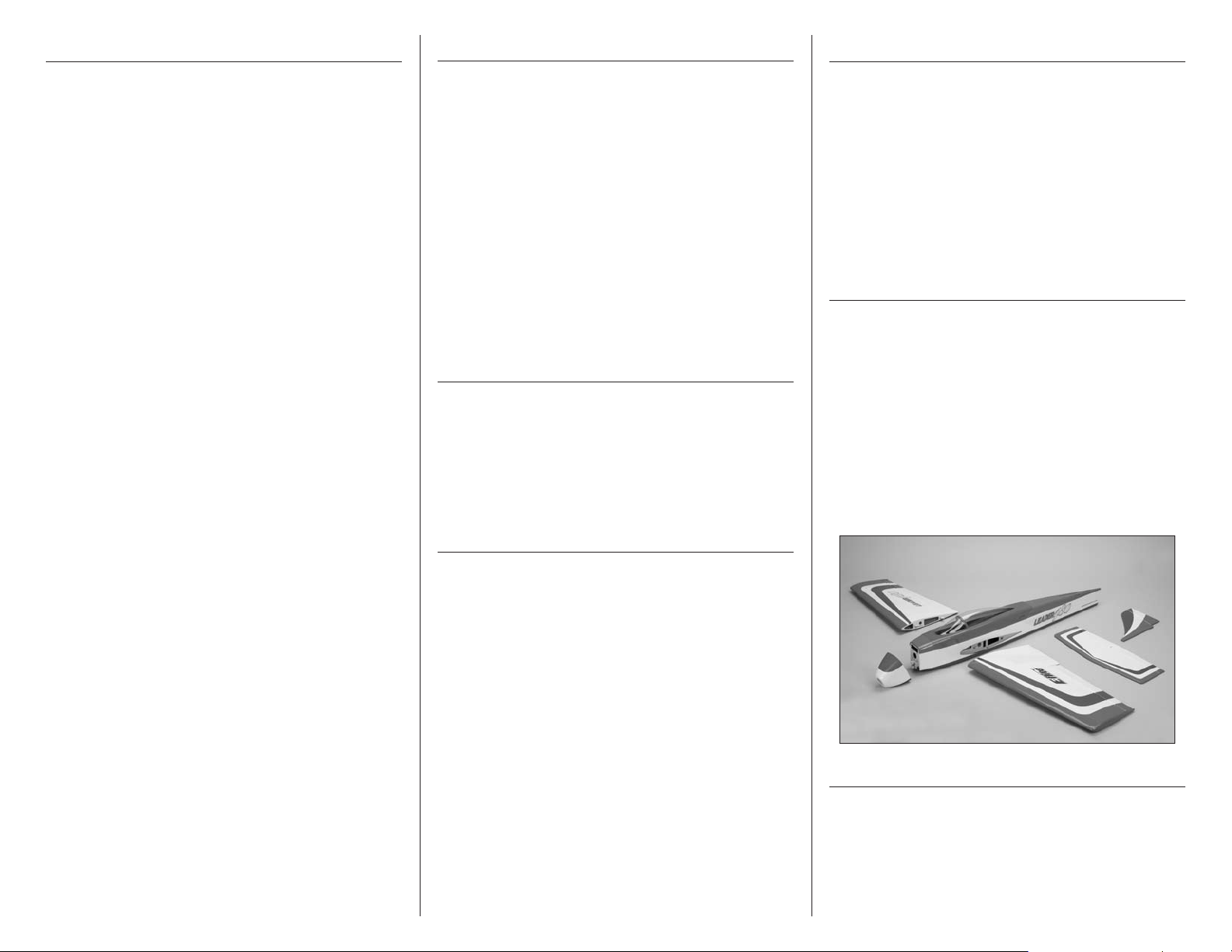
Table of Contents
Introduction
Using the Manual
Notice ......................................................................2
Meaning of Special Language ...................................2
Warnings .................................................................2
Introduction .............................................................. 3
Important Information Regarding
Warranty Information .......................................3
Specifications ...........................................................3
Using the Manual .....................................................3
Contents of Kit/Parts Layout ......................................3
Covering Colors ........................................................3
Hardware/Accessory Sizes ....................................... 4
Recommended Radio Equipment ................................4
480 Motor Setup ......................................................4
Optional Accessories ................................................4
Required Tools and Adhesives ...................................4
Before Starting Assembly ..........................................4
Hinging the Ailerons .................................................5
Aileron Servo Installation ..........................................6
Rudder and Elevator Servo Installation ....................... 8
Nose Gear Installation ............................................10
Receiver Installation................................................. 11
Motor and Speed Control Installation ....................... 12
Cowling and Spinner Installation .............................13
Main Landing Gear Installation ...............................15
Wing Installation ....................................................16
Stabilizer Installation ............................................... 17
Vertical Fin Installation ............................................18
Rudder and Elevator Installation ..............................19
Motor Battery Installation......................................... 22
Optional Pilot Installation......................................... 22
Center of Gravity .................................................... 23
Control Throws .......................................................24
Preflight ..................................................................24
Range Test Your Radio .............................................25
Flying Your Model ...................................................25
Daily Flight Checks ................................................. 26
Warranty and Repair Policy .................................... 26
Warranty Services ..................................................27
Compliance Information for the European Union ...... 27
Academy of Model Aeronautics
National Model Aircraft Safety Code ..............28
The nimble Leader 480 park flyer is a fun-to-fly
sport plane that is ideal for anyone interested in
precision aerobatics. Its light wing loading will put any
intermediate pilot at ease when flying the slow side of
the envelope. But if you really want to wring it out, its
symmetrical airfoil and classic pattern plane lines will
allow you to fly precision aerobatics with the best of
them.
Assembly is so simple, you could easily have it flightready in a single evening. Plus, it’s small enough you
can put it in the backseat or trunk of your car and fly it
most anywhere park flyers are allowed.
Important Information
Regarding Warranty Information
Please read our Warranty and Liability Limitations
section before building this product. If you as the
Purchaser or user are not prepared to accept the
liability associated with the use of this Product, you are
advised to return this Product immediately in new and
unused condition to the place of purchase.
Specifications
Wingspan: 43.0 in (1100mm)
Length: 42.4 in (1080mm)
Wing Area: 414 sq in (26.7 sq dm)
Weight with Battery: 39–41 oz (1110–1170 g)
Weight w/o Battery: 33–35 oz (935–990 g)
This manual is divided into sections to help make
assembly easier to understand, and to provide breaks
between each major section. In addition, check boxes
have been placed next to each step to keep track
of its completion. Steps with a single circle () are
performed once, while steps with two or more circles
() indicate the step will require repeating, such as
for a right or left wing panel, two servos, etc.
Remember to take your time and follow the directions.
Contents of Kit/Parts Layout
Replacement Parts
EFL300001 Fuselage
EFL300002 Wing Set
EFL300003 Tail Set
EFL300004 Cowling
EFL300005 Landing Gear Strut Set
EFL300006 Canopy Hatch
EFL300007 Main Wheel Set
EFL300008 Wing Tube
EFL300009 Hardware Package
EFL300010 Pushrod Set
Covering Colors
True Red HANU866
Deep Blue HANU873
White HANU870
3E-flite Leader 480 ARF Assembly Manual
Page 4

Hardware/Accessory Sizes
Optional Accessories
Before Starting Assembly
Wheel diameter 2-in (51mm)
Wing bolts 3mm x 10mm socket
head cap screw
Recommended Radio Equipment
You will need a minimum 4-channel transmitter,
receiver and four servos. You can choose to purchase
a complete radio system. If you are using an
existing transmitter, just purchase the other required
equipment separately. We recommend the crystalfree, interference-free Spektrum™ DX6 2.4GHz DSM®
6-channel system. If using your own transmitter, we
recommend the following radio equipment.
If you own the Spektrum DX6i radio, or you are
using a different DSM2
6-channel DSMX microlite receiver and four E-flite®
DS76 servos.
Complete Radio System
SPM6610 DX6i DSMX 6CH system
Or Purchase Separately
SPMAR6115 AR6115 6CH DSMX™
EFLRDS76 DS76 Digital Servo (4)
EFLREX3L 3-inch (76mm) Servo Extension
EFLREX6L 6-inch (152mm)
™
radio, just add the AR6115
Microlite Receiver
Servo Extension (3)
480 Motor Setup
EFLA110 Power Meter
EFLC505 Intelligent 1- to 5-Cell
Balancing Charger
EFLAEC312 Charge Lead with 12-inch
Wire and Jacks, 16AWG
EFLSP175 13/4-inch Aluminum Spinner
with 4mm and 5mm Collets
EFLA156 1/9 Civilian Pilot, Blue
with Glasses
Required Tools and Adhesives
Tools & Equipment
Box wrench: 10mm Felt-tipped pen
Flat file Hex wrench: 1.5mm, 2.5mm
Low-tack tape Pin vise
Ruler Scissors
Side cutter Square
T-pins Two-sided tape
String or dental floss
Drill bit: 1/16-inch (1.5mm), 5/64-inch (2mm)
Hobby knife with #11 blade
Phillips screwdriver: #0, #1, #2
Optional Tools & Equipment
Balancing stand (optional)
Adhesives
Medium CA PAAPT02
Thin CA PAAPT08
Threadlock PAAPT42
Before beginning the assembly of your model, remove
each part from its bag for inspection. Closely inspect
the fuselage, wing panels, rudder and stabilizer for
damage. If you find any damaged or missing parts,
contact the place of purchase.
If you find any wrinkles in the covering, use a heat gun
(HAN100) and covering glove (HAN150) or covering
iron (HAN101) with a sealing iron sock (HAN141) to
remove them. Use caution while working around areas
where the colors overlap to prevent separating the
colors.
During the course of building your model we
suggest you use a soft base for the building surface.
Such things as a foam stand, large piece of
bedding foam or a thick bath towel will work well
and help protect the model from damage during
assembly. This is not shown in the instructions
to provide the greatest detail in the photos.
EFLM1515 Park 480
EFLA1040L 40-Amp Pro Lite SB
Brushless ESC
EFLB21003S30 2100mAh 3S 11.1V 30C Li-Po,
12AWG EC3
APC12060E 12 x 6E Electric Propeller
4 E-flite Leader 480 ARF Assembly Manual
Page 5
Hinging the Ailerons
Required Parts
Wing panel with aileron (left and right)
Required Tools and Adhesives
Thin CA T-pins
Pin vise Drill bit: 1/16-inch (1.5mm)
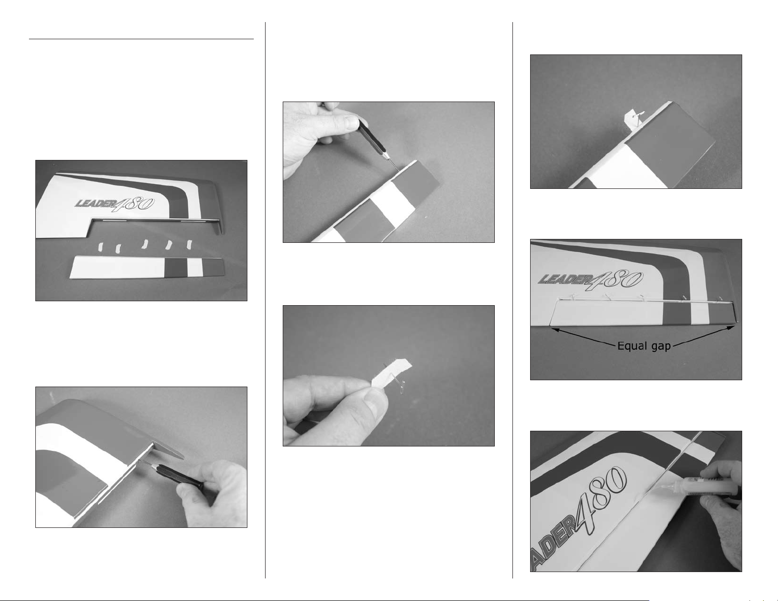
1. Separate the aileron from the wing. Set the five CA
hinges aside.
2. Use a pin vise and 1/16-inch (1.5mm) drill bit
to drill a hole in the center of each hinge slot in
the aileron to create a tunnel for the CA to wick
into. This will allow the CA to penetrate the hinge,
creating a better bond between the hinge and
surrounding wood.
3. Place a T-pin in the center of each of the five
hinges. This will center the hinges equally in the
aileron and wing when they are installed.
4. Insert the hinges in the ailerons. The T-pin will rest
on the edge of the aileron bevel.
5. Slide the aileron back into position. Center the
aileron so the gap at the ends is equal.
2. Use a pin vise and 1/16-inch (1.5mm) drill bit to
drill a hole in the center of each hinge slot in the wing
to create a tunnel for the CA to wick into. This will
allow the CA to penetrate the hinge, creating a better
bond between the hinge and surrounding wood.
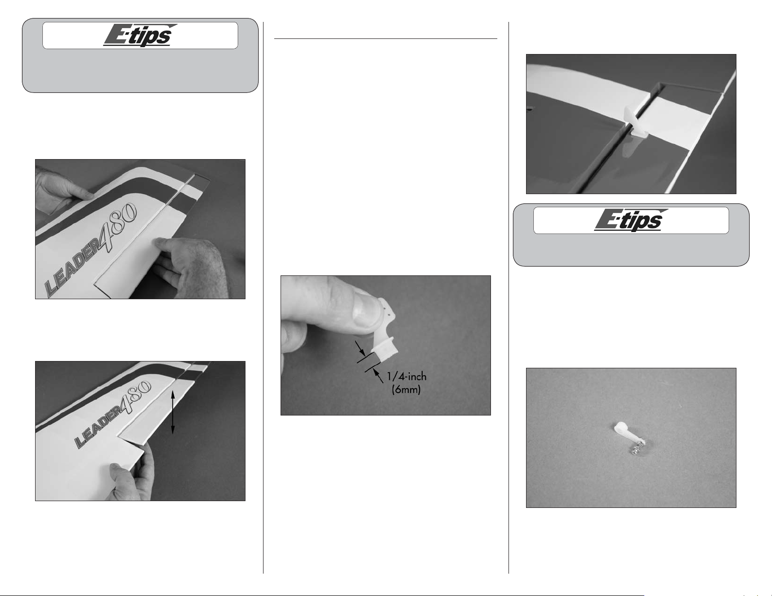
6. Saturate each hinge with thin CA. Apply CA to
both the top and bottom of the hinge.
5E-flite Leader 480 ARF Assembly Manual
Page 6
Do not use CA accelerator when gluing the hinges.
The CA must be allowed to soak into the hinge for the
best bond between the hinge and surrounding wood.
7. Once the CA has cured, gently pull on the control
surface and wing to make sure the hinges are glued
securely. If not, apply CA to those hinges that are not
glued and recheck.
Aileron Servo Installation
Required Parts
Transmitter Receiver
Receiver battery Servo with hardware (2)
Assembled wing panel (left and right)
Nylon control horn (2)
6-inch (152mm ) servo extension (2)
Micro screw-lock connector (2)
1mm x 180mm pushrod (2)
Required Tools and Adhesives
Side cutter Phillips screwdriver: #0, #1
Pin vise Thin CA
Medium CA String or dental floss
Threadlock Ruler
T-pins
Drill bit: 1/16-inch (1.5mm), 5/64-inch (2mm)
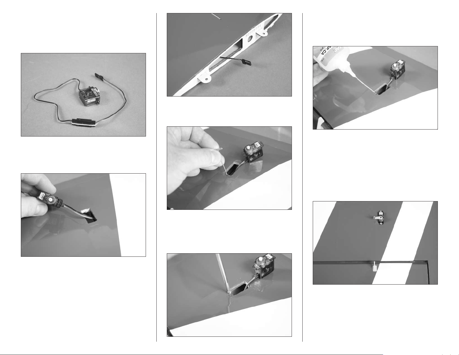
2. Use medium CA to glue the control horn in the slot
made in the bottom of the aileron.
8. Move the aileron through its range of motion
several times to break in the hinges. This will reduce
the initial load on the servo during your first flights.
9. Repeat steps 1 through 8 to hinge the
remaining aileron.
1. Use side cutters to trim the length of the control
horn to 1/4-inch (6mm) as shown.
Always use threadlock on metal-to-metal fasteners
to prevent them from vibrating loose.
3. Prepare the servo horn by enlarging the
outermost hole in a long single-sided servo horn
using a pin vise and 5/64-inch (2mm) drill bit.
Secure the micro screw-lock connector to the
servo horn using the hardware provided with the
connector. Make sure to use threadlock on the nut to
prevent it from vibrating loose.
6 E-flite Leader 480 ARF Assembly Manual
Page 7
4. Connect a 6-inch (152mm) servo extension to the
servo lead. Use string of dental floss to secure the
leads so they do not accidentally disconnect inside
the wing. Use a #0 Phillips screwdriver to remove the
servo horn from the servo.
5. Insert the servo lead into the wing. Tip the wing
tip up and guide the lead out of the wing at the
wing root.
8. Apply 2–3 drops of thin CA in each of the holes
to harden the surrounding wood. This will harden
the threads so the screws do not easily strip the
surrounding wood.
6. Use a T-pin to puncture the covering, locating the
openings for the servo mounting screws.
9. Secure the servo in the wing using the screws
provided with the servo and a #1 Phillips screwdriver.
The output shaft of the servo faces toward the aileron
as shown. Center the aileron servo using the radio
system. Attach the servo horn prepared in step 3
using the screw removed in step 4 and a #0 Phillips
screwdriver. Note that the servo horn is parallel to the
aileron hinge line.
7. Use a #1 Phillips screwdriver to thread a servo
mounting screw into each of the holes to cut threads
in the surrounding wood. Remove the screw before
moving to the next step.
Note: It may be necessary to trim the servo
opening for the servo used.
7E-flite Leader 480 ARF Assembly Manual
Page 8
10. Pass the Z-bend in the 1mm x 180mm pushrod
through the outer hole of the aileron control horn.
Always use threadlock on metal-to-metal fasteners
to prevent them from vibrating loose.
11. The pushrod wire will pass through the hole in
the micro screw-lock connector. With the aileron
and aileron servo centered, use side cutters to
trim the pushrod so it is 1/4 inch (6mm) past the
connector as shown. Pass pushrod through micro
screw-lock connector. Use a #1 Phillips screwdriver
to tighten the screw in the connector to secure the
pushrod wire.
Use a small piece of low-tack tape to hold the aileron
in position when installing the linkage. Remove
the tape once the linkage has been installed.
12. Repeat steps 1 through 11 to install the remaining
aileron servo and pushrod.
Rudder and Elevator Servo Installation
Required Parts
Fuselage Servo with hardware (2)
Transmitter Receiver
Receiver battery Micro screw-lock connector (3)
Required Tools and Adhesives
Pin vise Phillips screwdriver: #0, #1
Thin CA Drill bit: 5/64-inch (2mm)
Threadlock
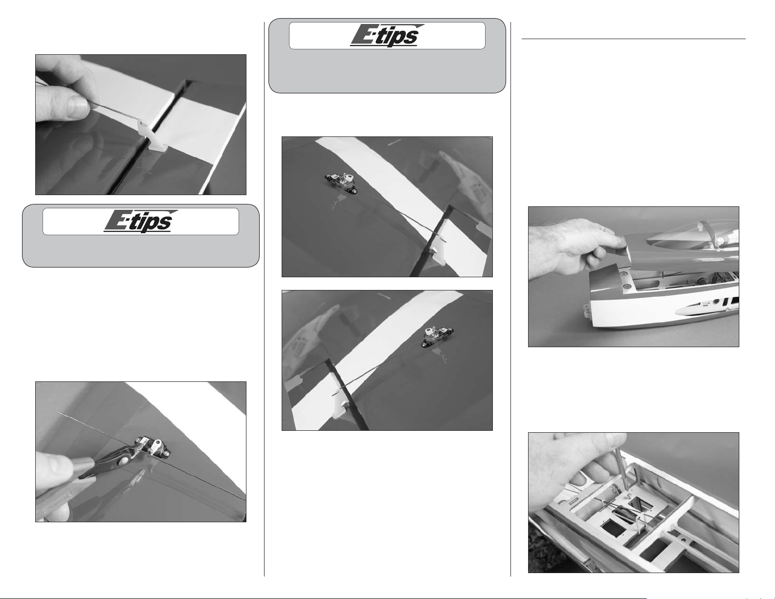
1. Remove the canopy from the fuselage. Lift the
canopy at the front to disconnect the magnets. The rear
is held in position using tabs that key into the fuselage.
2. Use a #1 Phillips screwdriver to thread a servo
mounting screw into each of the holes to cut threads
in the surrounding wood. Remove the screw before
moving to the next step. Prepare all four mounting
holes at this time.
8 E-flite Leader 480 ARF Assembly Manual
Page 9
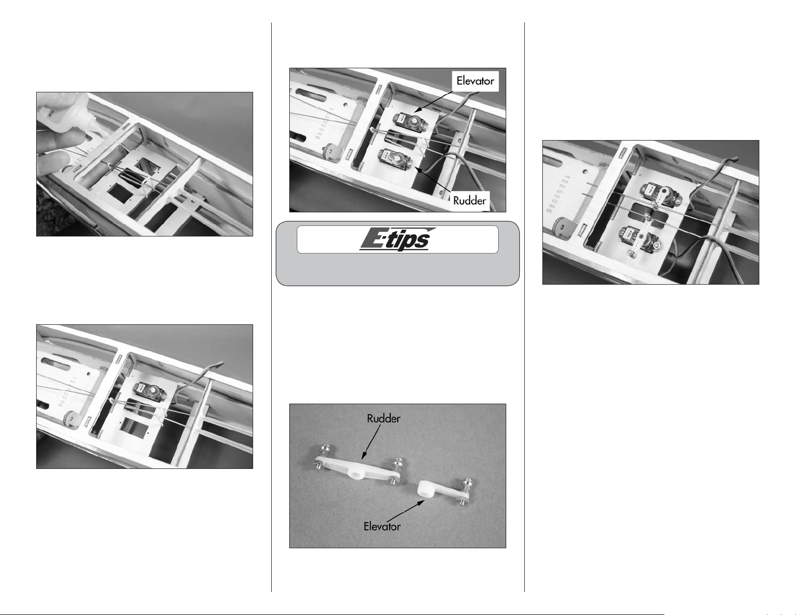
3. Apply 2–3 drops of thin CA in each of the holes
to harden the surrounding wood. This will harden
the threads so the screws do not easily strip the
surrounding wood. Prepare all four mounting holes
at this time.
5. Repeat step 4 to install the rudder servo in the
fuselage. The output of the rudder servo faces the rear
of the fuselage when installed.
7. Use the radio system to center the rudder and
elevator servos. Attach the servo horns prepared
in step 6 on the rudder and elevator servos using
the screw previously removed from the servos and
a #0 Phillips screwdriver. Remove the rubber band
that holds the pushrod in the fuselage. Pass the
pushrod through the connectors and tighten the
screws to prevent the pushrod from falling out of
the fuselage accidentally.
4. Secure the elevator servo in the fuselage using
the screws provided with the servo and a #1 Phillips
screwdriver. The output shaft of the servo faces the
rear of the fuselage when installed. Remove the servo
horn from the servo using a #0 Phillips screwdriver.
Always use threadlock on metal-to-metal fasteners
to prevent them from vibrating loose.
6. Prepare the rudder and elevator servo horns by
enlarging the outermost hole in a long single-sided
(elevator) or long double-sided (rudder) servo horn
using a pin vise and 5/64-inch (2mm) drill bit. Secure
micro screw-lock connectors to the servo horns using
the hardware provided with the connectors. Make
sure to use threadlock on the nuts to prevent them
from vibrating loose.
9E-flite Leader 480 ARF Assembly Manual
Page 10
Nose Gear Installation
Required Parts
Fuselage assembly Nose wheel steering arm
51mm foam wheel Pre-formed nose gear wire
Transmitter Receiver
Receiver battery
2.5mm wheel collar with setscrew (2)
1mm x 445mm pushrod with guide tube
Required Tools and Adhesives
Thin CA Phillips screwdriver: #2
Flat file Hex wrench: 1.5mm
Threadlock Side cutter
Sandpaper
2. Insert the Z-bend of the pushrod wire into the nose
gear steering arm as shown.
4. Use a flat file to make a 1/4-inch (6mm) wide flat
on the bottom of the nose gear wire. This will provide
a place to tighten the setscrew when the wheel collar
is installed.
1. Slide the pushrod guide tube in the fuselage as
shown. Use sandpaper to scuff the tube where it
passes the mounts in the fuselage so the CA will
adhere to the tube. The end of the tube will protrude
from the fuselage by 1/32-inch (1mm) use thin CA to
glue the tube in the fuselage at the positions shown.
3. Slide the pushrod wire through the tube and into
the fuselage. Guide the wire through the connector on
the rudder servo horn. The steering arm will fit in the
bracket as shown.
Always use threadlock on metal-to-metal fasteners
to prevent them from vibrating loose.
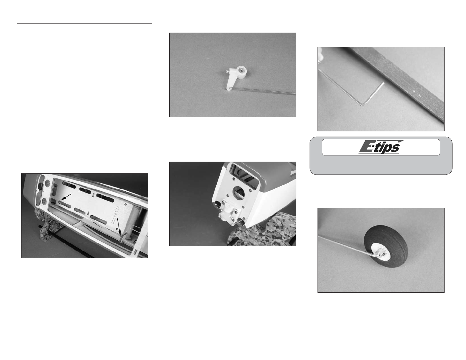
5. Attach the wheel to the nose gear wire using two
2.5mm wheel collars and setscrews. Tighten the
setscrews using a 1.5mm hex wrench.
10 E-flite Leader 480 ARF Assembly Manual
Page 11

Always use threadlock on metal-to-metal fasteners
to prevent them from vibrating loose.
6. Slide the nose gear wire into the bracket and
steering arm. Use a #2 Phillips screwdriver to tighten
the screw in the steering arm on the flat of the nose
gear wire.
7. Use the radio system to center the rudder servo.
Align the nose gear so the wheel is parallel to the
fuselage centerline. Tighten the screw in the pushrod
connector to secure the pushrod wire. Use side cutters
to trim the excess pushrod wire 1/4-inch (6mm) past
the connector as shown.
When trimming the airplane to track straight on the
ground, the adjustment is made in the linkage for the
nose wheel steering, not with the rudder trim. This will
cause the rudder to become out of trim in the air.
Receiver Installation
Required Parts
Fuselage assembly Receiver
3-inch (76mm) servo extension
Hook and loop tape (not included)
Required Tools and Adhesives
Scissors
1. Plug the rudder and elevator servos into the
appropriate ports of the receiver. Also plug a
3-inch (76mm) servo extension into the port for
the left aileron.
Always use threadlock on metal-to-metal fasteners
to prevent them from vibrating loose.
2. Use scissors to cut a piece of hook and loop tape
(not included) the size of the receiver. Use the tape to
secure the receiver inside the fuselage.
11E-flite Leader 480 ARF Assembly Manual
Page 12

Motor and Speed Control Installation
Required Parts
Fuselage assembly Motor with hardware
Speed control 3mm washer (4)
3mm lock washer (4)
Two-sided tape (not included)
6-inch (152mm) servo extension
3mm x 30mm socket head cap screw (4)
Aluminum motor standoff, 18mm (4)
Required Tools and Adhesives
Phillips screwdriver: #1
Hex wrench: 2.5mm
Always use threadlock on metal-to-metal fasteners
to prevent them from vibrating loose.
2. Secure the motor to the firewall using the four
18mm aluminum motor standoffs, four 3mm x
30mm socket head cap screws, four 3mm washers
and four 3mm lock washers. Use a 2.5mm hex
wrench to tighten the screws. Make sure to use
threadlock on these screws as well to prevent them
from vibrating loose.
Matching the colors between the ESC and motor
when they are connected results in the correct
motor direction if using all E-flite components.
4. Connect the leads from the motor to the speed
control. Once connected, tuck the leads back in the
fuselage to prevent them from interfering with the
operation of the motor.
1. Attach the X-mount to the motor using the
hardware included with the motor and a #1
Phillips screwdriver
3. Place the speed control in the fuselage. It will fit
between the side and sub-side of the fuselage as
shown. Pass the leads for the motor through the
opening at the top of the firewall as shown in the
following step. Use two-sided tape to secure the speed
control in the fuselage.
5. Plug the lead from the speed control into the throttle
port of the receiver at this time.
12 E-flite Leader 480 ARF Assembly Manual
Page 13

Cowling and Spinner Installation
Required Parts
Fuselage assembly Spinner (optional)
Cowling Propeller
#0 Phillips head wood screw (4)
Required Tools and Adhesives
Low-tack tape Pin vise
Thin CA Phillips screwdriver: #1
Box wrench: 10mm
Hex wrench: 2.5mm
Drill bit: 1/16-inch (1.5mm), 5/64-inch (2mm)
2. Slide the cowling on the fuselage.
4. Use low-tack tape to hold the cowling in
position for the following step. Make sure the
propeller can rotate without the backplate rubbing
against the cowling.
Always balance your propeller. An unbalanced
propeller can cause vibrations to be transmitted
into the airframe, which could damage the
airframe or other components as well as
produce unwanted flight characteristics.
We recommend using the optional spinner
to enhance the looks of your model.
1. Install the propeller on the spinner assembly. Do
not tighten the propeller nut so the assembly can be
placed on the motor shaft.
Place a piece of 3/32-inch (2.5mm) thick two-
sided tape (not included) between the cowling
and spinner backplate to set the spacing. This will
also hold the cowling in position at the front so
it can be positioned easily at the rear to match
the paint lines from the cowl to the fuselage.
3. Slide the propeller/spinner on the motor shaft.
Position the cowl so there is a gap of 3/32-inch
(2mm) between the spinner backplate and cowl.
5. Measure 3/16-inch (5mm) forward of the edge of
the cowl, and in 3/16-inch (5mm) from the paint lines
on the cowl. Use a pin vise with a 1/16-inch (1.5mm)
drill bit to drill four holes through the cowling and
fuselage side for the cowl mounting screws.
13E-flite Leader 480 ARF Assembly Manual
Page 14

6. Remove the propeller and cowl from the fuselage.
Enlarge the holes in the cowl using a pin vise and
5/64-inch (2mm) drill bit.
7. Use a #1 Phillips screwdriver to thread a #0
Phillips head wood screw into each of the holes to
cut threads in the surrounding wood. Remove the
screw before moving to the next step. Prepare all four
mounting holes at this time.
8. Apply 2–3 drops of thin CA in each of the holes
to harden the surrounding wood. This will harden
the threads so the screws do not easily strip the
surrounding wood. Prepare all four mounting holes
at this time.
9. Once the CA has cured, use four #0 Phillips head
wood screws and a #1 Phillips screwdriver to secure
the cowl to the fuselage.
10. Slide the propeller/spinner on the motor shaft.
Use a 10mm box wrench to tighten the nut securing
the assembly to the motor shaft.
11. Place the spinner cone on the propeller. Use
the screw included with the spinner assembly and a
2.5mm hex wrench to secure the cone in position.
14 E-flite Leader 480 ARF Assembly Manual
Page 15

Main Landing Gear Installation
Required Parts
Wing panel assembly (left and right)
Pre-bent main landing gear (2)
#2 Phillips head wood screw (8)
Nylon landing gear strap (4)
51mm foam wheel (2)
2.5mm wheel collar with setscrew (4)
Required Tools and Adhesives
Flat file Hex wrench: 1.5mm
Threadlock Phillips screwdriver: #2
Thin CA
1. Use a #1 Phillips screwdriver to thread a #0
Phillips head wood screw into each of the holes to
cut threads in the surrounding wood. Remove the
screw before moving to the next step. Prepare all four
mounting holes at this time.
2. Apply 2–3 drops of thin CA in each of the holes
to harden the surrounding wood. This will harden
the threads so the screws do not easily strip the
surrounding wood. Prepare all four mounting holes
at this time.
3. Use a flat file to make a 1/4-inch (6mm) wide flat
area on the bottom of the landing gear wire. This
will provide a place to tighten the setscrew when the
wheel collar is installed.
4. Insert the landing gear wire into the wing. It will
rest flush with the wing as shown in the second photo
when installed.
5. Use two nylon landing gear straps and four #2
Phillips head wood screws to secure the main landing
gear to the wing.
15E-flite Leader 480 ARF Assembly Manual
Page 16

Always use threadlock on metal-to-metal fasteners
to prevent them from vibrating loose.
6. Use two 2.5mm wheel collars to secure the 51mm
foam wheel to the landing gear. The setscrews are
tightened using a 1.5mm hex wrench.
7. Repeat steps 1 through 6 to install the remaining
landing gear and wheel.
Wing Installation
Required Parts
Wing panel with aileron (left and right)
Aluminum wing tube
3mm x 10mm socket head cap screw (4)
3mm washer (4)
Required Tools and Adhesives
Hex wrench: 2.5mm
1. Slide the aluminum wing tube into the socket in
the wing panel. The tube will slide in easily, so do not
force it in any farther than it will easily slide.
3. Use two 3mm x 10mm socket head cap screws
and two 3mm washers to secure the position of the
wing. Use a 2.5mm hex wrench to tighten the screws.
Plug the aileron servo into the receiver if you are
preparing your model for flight.
4. Repeat step 3 to install the second wing panel.
2. Slide the tube into the socket in the fuselage. Make
sure to guide the lead for the aileron servo in the
fuselage when positioning the wing.
16 E-flite Leader 480 ARF Assembly Manual
Page 17

Stabilizer Installation
A A
A=A
Check alignment
A A
A=A
Required Parts
Fuselage assembly Stabilizer
Required Tools and Adhesives
Thin CA Felt-tipped pen
Ruler Hobby knife with #11 blade
1. Remove the elevator from the stabilizer. Set
the elevator and four CA hinges aside until later.
Use a felt-tipped pen and ruler to mark a center
on the trailing edge of the stabilizer. This will
provide a starting point when checking the
alignment of the stabilizer.
2. Measure the distance from each stabilizer tip to
the fuselage centerline to make sure the stabilizer is
centered on the fuselage.
3. Stand back 8–10 feet (2–3 meters) and view the
aircraft from the rear. Check the alignment between
the wing and stabilizer. They must be equal distance
on each side as shown. If not, lightly sand the
stabilizer saddle to correct any alignment problems.
4. Measure the distance from each stabilizer tip to
the outside corner of the aileron hinge line. These
measurements must match as close as possible.
Adjust the position of the stabilizer if necessary to
position the stabilizer.
5. Once the stabilizer has been aligned to the wing,
use a felt-tipped pen to trace the outline of the
fuselage on the bottom of the stabilizer.
It is important to check the alignment of the
stabilizer in relationship to the wing. Not doing
so may cause your airplane to require excessive
amounts of trim to correct for poor alignment,
resulting in poor flight performance.
17E-flite Leader 480 ARF Assembly Manual
Page 18

Vertical Fin Installation
When cutting through the covering, use a
new #11 blade and light pressure to avoid
cutting into the underlying wood, which could
weaken the underlying structure, causing it
to fail in flight. We also recommend using a
hot knife to melt through the covering to help
reduce damaging the underlying wood.
6. Remove the stabilizer from the fuselage. Use a
hobby knife and #11 blade to trim the covering
inside the lines drawn in the previous step by 1/16-
inch (1.5mm). Remove the covering, exposing the
bare wood. The lines can be removed using a
paper towel and rubbing alcohol.
Do not use CA accelerator when gluing the
stabilizer to the fuselage. The CA must be
allowed to soak into the fuselage and stabilizer
for the best bond between the two surfaces.
7. Place the stabilizer back on the fuselage. Recheck
the alignment. Wick thin CA into the joint between
the stabilizer and fuselage. Allow the CA to fully
cure before proceeding.
Required Parts
Fuselage assembly Fin
Required Tools and Adhesives
Felt-tipped pen Thin CA
Square Hobby knife with #11 blade
1. Remove the rudder from the fin. Set the rudder and
three CA hinges aside until later. Place the fin in the
slot on the top of the fuselage.
2. Use a felt-tipped pen to trace the outline of the
fuselage on the bottom of the fin.
18 E-flite Leader 480 ARF Assembly Manual
Page 19

When cutting through the covering, use a
Align 90-degrees
new #11 blade and light pressure to avoid
cutting into the underlying wood, which could
weaken the underlying structure, causing it
to fail in flight. We also recommend using a
hot knife to melt through the covering to help
reduce damaging the underlying wood.
3. Remove the fin from the fuselage. Use a hobby
knife and #11 blade to trim the covering below
the lines drawn in the previous step by 1/16-inch
(1.5mm). Remove the covering, exposing the bare
wood. The lines can be removed using a paper
towel and rubbing alcohol.
4. Place the fin back in the slot on the top of the
fuselage. Use a square to make sure the fin is
positioned 90-degrees to the stabilizer. If not, lightly
sand the exposed wood on the bottom of the fin to
correct its alignment.
Do not use CA accelerator when gluing the
fin to the fuselage. The CA must be allowed
to soak into the fuselage and fin for the
best bond between the two surfaces.
Rudder and Elevator Installation
Required Parts
Fuselage assembly Rudder
Elevator Control horn with backplate (2)
CA hinge (7)
Required Tools and Adhesives
Thin CA T-pins
Pin vise Drill bit: 1/16-inch (1.5mm)
Threadlock Side cutter
1. Use a pin vise and 1/16-inch (1.5mm) drill bit to
drill a hole in the center of each hinge slot to create
a tunnel for the CA to wick into. This will allow the
CA to penetrate the hinge, creating a better bond
between the hinge and surrounding wood. Prepare
the rudder and fin at this time.
5. Once aligned, wick thin CA into the joint
between the fin and fuselage. Allow the CA to fully
cure before proceeding.
2. Place T-pin in the center of each of the three rudder
(or four elevator) hinges. This will center the hinges
equally in each surface when they are installed.
19E-flite Leader 480 ARF Assembly Manual
Page 20

3. Insert the hinges in the rudder (or elevator).
The T-pin will rest on the edge of the bevel of the
control surface.
4. Slide the rudder (or elevator) into position. Make
sure the tip of the control surface is aligned with the
tip of the fixed surface.
5. Saturate each hinge with thin CA. Apply CA to
both side of the hinge.
Do not use CA accelerator when gluing the hinges.
The CA must be allowed to soak into the hinge for the
best bond between the hinge and surrounding wood.
6. Once the CA has cured, gently pull on the control
surface and fin to make sure the hinges are glued
securely. If not, apply CA to those hinges that are not
glued and recheck.
7. Move the rudder through its range of motion a
number of times to break in the hinges. This will
reduce the initial load on the servo during your
first flights.
8. Pass the Z-bend in the rudder (or elevator) pushrod
through the outer hole of the control horn.
20 E-flite Leader 480 ARF Assembly Manual
Page 21

9. Insert the control horn in the slit in the rudder
(or elevator).
10. Slide the control horn backplate over the end of
the control horn from the opposite side of the control
surface. Snap the backplate so the horn is held
tightly in position. Apply 2–3 drops of thin CA to the
backplate where it contacts the control horn to keep it
from accidentally coming loose in flight.
Before gluing the backplate in position, trim the
front edge of the backplate so it does not cause
binding in extreme throws. Temporarily snap the
backplate into position and mark the backplate
along the bevel with a felt tipped pin. Remove
the backplate and use side cutters to trim the
backplate. Use sandpaper to sand the backplate
to its to final shape before gluing it in position.
12. Repeat steps 1 through 11 to install the elevator
and associated hardware.
Always use threadlock on metal-to-metal fasteners
to prevent them from vibrating loose.
11. Use the radio system to center the rudder servo.
Center the rudder so it is aligned with the fin (or
the elevator to the stabilizer). Tighten the screw in
the pushrod connector to secure the pushrod wire.
Use side cutters to trim the excess length of wire that
extends beyond the connector as shown.
21E-flite Leader 480 ARF Assembly Manual
Page 22

Motor Battery Installation
Optional Pilot Installation
Required Parts
Fuselage assembly Motor battery
Hook and loop strap (not included) (2)
Hook and loop tape (not included)
1. Secure the motor battery in the fuselage using two
hook and loop straps (not included). We recommend
using hook and loop tape between the battery and
battery tray to keep the battery from sliding on the
tray during flight.
Required Parts
Canopy Pilot (optional)
Balsa stiffener (2)
Required Tools and Adhesives
Felt-tipped pen Ruler
Razor saw Medium CA
Sanding block Medium grit sandpaper
Hobby knife with #11 blade
1. Use a felt-tipped pen to mark the pilot 1/2-inch
(13mm) up from the bottom as shown.
3. Remove the balsa plate from the inside of the
portion of the pilot trimmed in the previous step. Fit
the plate into the bottom of the pilot. You may need
to lightly sand the plate to fit. Once fit, use medium
CA to glue the plate in the pilot. Allow the CA to fully
cure before proceeding.
2. Use a razor saw to trim the pilot along the line
Make sure not to wrap the hook and loop strap
around any wires or pushrods. Wrapping it
around the steering pushrod will increase the
load on the rudder servo, which could cause
the servo to fail due to the increased loads.
22 E-flite Leader 480 ARF Assembly Manual
made in the previous step. Use a sanding block and
medium grit sandpaper to smooth the bottom of the
pilot flat.
4. Use medium CA to glue the two balsa stiffeners to
the bottom of the pilot. These will keep the pilot from
falling into the canopy, and provide a way to secure
the pilot.
Page 23

5. Use a hobby knife and #11 blade to remove
Balancing Stand
the covering from the canopy. Test fit the pilot into
the canopy. It may be necessary to lightly sand to
opening to fit the pilot.
Center of Gravity
Required Parts
Assembled airframe
Required Tools and Adhesives
Felt-tipped pen Ruler
Phillips screwdriver: #2
Balancing stand (optional)
An important part of preparing the aircraft for flight is
properly balancing the model.
CAUTION: Do not inadvertently skip this step or
property damage and injury could occur.
1. Assemble your model in preparation for flight,
making sure the wing is on securely and the motor
battery is installed as instructed in this manual.
2. The recommended Center of Gravity (CG)
location for your model is 33/8 to 33/4 inches (85
to 95mm) back from the leading edge of the wing
as shown with the battery pack installed. Mark the
location of the CG on the top of the wing with a
felt-tipped pen.
3. When balancing your model, support the plane
inverted at the marks made on the top of the wing
with your fingers or a commercially available
balancing stand. This is the correct balance point
for your model. Make sure your model is assembled
and ready for flight before balancing.
Adjust the motor battery as necessary so the model is
level or slightly nose down. This is the correct balance
point for your model. You should find the CG to be
very close with the battery installed as shown in this
manual. Mark the location of the battery on the battery
tray using a felt-tipped pen so it can be returned to this
position if it is removed from your model.
6. Once satisfied with the fit, use medium CA to glue
the pilot in the canopy. Apply the glue to the stiffeners
to keep the pilot in the canopy.
After the first flights, the CG position can be adjusted
for your personal preference.
23E-flite Leader 480 ARF Assembly Manual
Page 24

Control Throws
1. Turn on the transmitter and receiver of your
model. Check the movement of the rudder using
the transmitter. When the stick is moved right, the
rudder should also move right. Reverse the direction
of the servo at the transmitter if necessary.
2. Check the movement of the elevator with the
radio system. Moving the elevator stick toward
the bottom of the transmitter makes the airplane
elevator move up.
3. Check the movement of the ailerons with the
radio system. Moving the aileron stick right makes
the right aileron move up and the left aileron
move down.
4. Use a ruler to adjust the throw of the elevator,
ailerons and rudder. Adjust the position of
the pushrod at the control horn to achieve the
following measurements when moving the sticks to
their endpoints.
Elevator High Rate (100%) (30% Exponential)
Up 23/32-inch (18mm)
Down 25/32-inch (20mm)
Elevator Low Rate (20% Exponential)
Up 5/16-inch (8mm)
Down 11/32-inch (9mm)
Rudder High Rate (100%) (30% Exponential)
Right 13/16-inch (30mm)
Left 13/16-inch (30mm)
Rudder Low Rate (20% Exponential)
Right 25/32-inch (20mm)
Left 25/32-inch (20mm)
Measurements are taken at the inner or
widest point on the control surface.
These are general guidelines measured from our own
flight tests. You can experiment with higher rates to
match your preferred style of flying.
Travel Adjust and Sub-Trims are not listed and
should be adjusted according to each individual
model and preference. Always install the control
horns 90-degrees to the servo centerline. Use
sub-trim as a last resort to center the servos.
We highly recommend re-binding the radio
system once all the control throws are set. This will
keep the servos from moving to their endpoints
until the transmitter and receiver connect.
Preflight
Check Your Radio
Before going to the field, be sure your batteries are
fully charged per the instructions included with your
radio. Charge the transmitter and motor battery
for your airplane. Use the recommended charger
supplied with your particular radio system, following
the instructions provided with the radio. In most
cases, the radio should be charged the night before
going out flying.
Before each flying session, be sure to range check your
radio. See your radio manual for the recommended
range and instructions for your radio system. Each
radio manufacturer specifies different procedures for
their radio systems. Next, run the motor. With the
model securely anchored, check the range again.
The range test should not be significantly affected. If
it is, don’t attempt to fly! Have your radio equipment
checked out by the manufacturer.
Double-check that all controls (aileron, elevator, rudder
and throttle) move in the correct direction.
Check the radio installation and make sure all the
control surfaces are moving correctly (i.e., the correct
direction and with the recommended throws).
Check all the control horns, servo horns, and clevises
to make sure they are secure and in good condition.
Aileron High Rate (100%) (40% Exponential)
Up 25/32-inch (20mm)
Down 25/32-inch (20mm)
Aileron Low Rate (33% Exponential)
Up 19/32-inch (15mm)
Down 19/32-inch (15mm)
24 E-flite Leader 480 ARF Assembly Manual
Page 25

Range Test Your Radio
Before each flying session, and especially with a new
model, it is important to perform a range check. It
is helpful to have another person available to assist
during the range check. If you are using a Spektrum
transmitter, please refer to your transmitter’s manual for
detailed instructions on the range check process.
1. With the model resting on the ground, stand 30
paces (approximately 90 feet) away from the model.
2. Face the model with the transmitter in your
normal flying position. Be sure the throttle is in the
full down position and plug the flight battery into
the speed control.
3. As you move the controls, watch to be sure the
airplane’s motor and controls operate smoothly.
You should have total control of the model at 30
paces (90 feet).
4. If control issues exist, call the appropriate
Horizon Product Support office (see page 43) or
go to horizonhobby.com to find a local Spektrum
distributor in your country for service if using a
Spektrum radio system.
Flying Your Model
The Leader 480 is an extremely well mannered lowwing park flyer with the heart of a pattern plane.
Its ground handling characteristics are very forgiving
due to the tricycle landing gear arrangement. Set the
throttle trim such that the propeller is spinning over at
a very low RPM. Taxi out to the runway and line up
with the centerline and check to ensure that the controls
are moving in the correct directions and that your rate
switches are set to their proper positions. Smoothly
advance the throttle and hold slight back pressure on
the elevator. Use very small rudder corrections to keep
the airplane tracking straight down the runway, and
the Leader should gently break ground after a short
takeoff roll and settle into a moderate climb angle.
Once at altitude, set cruise power to between ½ to
¾ throttle and trim for straight and level flight. After
trimming and making a few passes, try some slow
flight. Point the nose into the wind and reduce power
and feed up elevator to maintain level flight. The
airplane will slow down to a crawl and break straight
ahead.
Now for the fun part. With the light weight of the
airframe, and the power of the Park 480 motor, the
Leader 480 is a very capable aerobatic performer.
Due to the force arrangement and the generous tail
moment, the Leader tracks incredible lines. Big loops,
slow axial rolls, snap rolls, inverted flight, spins, stall
turns, and more are well within this agile flyer’s realm
of capability. Use your imagination to create your own
aerobatic sequence for endless fun.
When the time comes bring this bird back to earth, fly
parallel to the runway downwind and slowly reduce
power. Begin to bleed off airspeed and descend. Once
lined up with the runway, use the elevator to control
airspeed and power to control rate of descent and
establish a stable glidepath to the approach end of the
runway. Once you are a few feet above the runway,
begin to shallow your descent rate and reduce power
completely. Once you settle into ground effect, it will
settle onto the runway in a slightly nose-high attitude.
If the nose is kept high during the roll out, speed will
bleed off much quicker. Just as with the takeoff, use
small rudder corrections to keep the airplane tracking
straight down the runway.
Congratulations, you have just flown your Leader 480!
We wish you many more happy flights with this model.
Now grab a battery and do it again!
Happy Landings!
25E-flite Leader 480 ARF Assembly Manual
Page 26

Daily Flight Checks
Warranty and Repair Policy
DAMAGE LIMITS
1. Check the battery voltage of the transmitter
battery. Do not fly below the manufacturer’s
recommended voltage. To do so can crash
your aircraft.
When you check these batteries, ensure you have the
polarities correct on your expanded scale voltmeter.
2. Check all hardware (linkages, screws, nuts, and
bolts) prior to each day’s flight. Be sure that binding
does not occur and that all parts are properly
secured.
3. Ensure all surfaces are moving in the
proper manner.
4. Perform a ground range check before each day’s
flying session.
5. Prior to starting your aircraft, turn off your
transmitter, then turn it back on. Do this each time
you start your aircraft. If any critical switches are on
without your knowledge, the transmitter alarm will
sound a warning at this time.
WARRANTY PERIOD
Exclusive Warranty- Horizon Hobby, Inc., (Horizon)
warranties that the Products purchased (the “Product”)
will be free from defects in materials and workmanship
at the date of purchase by the Purchaser.
LIMITED WARRANTY
Horizon reserves the right to change or modify this
warranty without notice and disclaims all other
warranties, express or implied.
(a) This warranty is limited to the original Purchaser
(“Purchaser”) and is not transferable. REPAIR
OR REPLACEMENT AS PROVIDED UNDER THIS
WARRANTY IS THE EXCLUSIVE REMEDY OF THE
PURCHASER. This warranty covers only those Products
purchased from an authorized Horizon dealer. Third
party transactions are not covered by this warranty.
Proof of purchase is required for all warranty claims.
(b) Limitations- HORIZON MAKES NO WARRANTY
OR REPRESENTATION, EXPRESS OR IMPLIED,
ABOUT NON-INFRINGEMENT, MERCHANTABILITY
OR FITNESS FOR A PARTICULAR PURPOSE OF THE
PRODUCT. THE PURCHASER ACKNOWLEDGES
THAT THEY ALONE HAVE DETERMINED THAT THE
PRODUCT WILL SUITABLY MEET THE REQUIREMENTS
OF THE PURCHASER’S INTENDED USE.
HORIZON SHALL NOT BE LIABLE FOR SPECIAL,
INDIRECT OR CONSEQUENTIAL DAMAGES, LOSS
OF PROFITS OR PRODUCTION OR COMMERCIAL
LOSS IN ANY WAY CONNECTED WITH THE
PRODUCT, WHETHER SUCH CLAIM IS BASED IN
CONTRACT, WARRANTY, NEGLIGENCE, OR STRICT
LIABILITY. Further, in no event shall the liability of
Horizon exceed the individual price of the Product on
which liability is asserted. As Horizon has no control
over use, setup, final assembly, modification or misuse,
no liability shall be assumed nor accepted for any
resulting damage or injury. By the act of use, setup or
assembly, the user accepts all resulting liability.
If you as the Purchaser or user are not prepared
to accept the liability associated with the use of
this Product, you are advised to return this Product
immediately in new and unused condition to the place
of purchase.
Law: These Terms are governed by Illinois law (without
regard to conflict of law principals).
6. Check that all trim levers are in the
proper location.
7. All servo pigtails and switch harness plugs should
be secured in the receiver. Make sure the switch
harness moves freely in both directions.
26 E-flite Leader 480 ARF Assembly Manual
(c) Purchaser Remedy- Horizon’s sole obligation
hereunder shall be that Horizon will, at its option,
(i) repair or (ii) replace, any Product determined
by Horizon to be defective. In the event of a defect,
these are the Purchaser’s exclusive remedies. Horizon
reserves the right to inspect any and all equipment
involved in a warranty claim. Repair or replacement
decisions are at the sole discretion of Horizon.
This warranty does not cover cosmetic damage or
damage due to acts of God, accident, misuse, abuse,
negligence, commercial use, or modification of or
to any part of the Product. This warranty does not
cover damage due to improper installation, operation,
maintenance, or attempted repair by anyone other
than Horizon. Return of any Product by Purchaser must
be approved in writing by Horizon before shipment.
Page 27

Warranty Services
QUESTIONS, ASSISTANCE, AND REPAIRS
Your local hobby store and/or place of purchase
cannot provide warranty support or repair. Once
assembly, setup or use of the Product has been started,
you must contact Horizon directly. This will enable
Horizon to better answer your questions and service
you in the event that you may need any assistance.
For questions or assistance, please direct your
email to productsupport@horizonhobby.com, or call
877.504.0233 toll free to speak to a Product Support
representative. You may also find information on our
website at www.horizonhobby.com.
INSPECTION OR REPAIRS
If this Product needs to be inspected or repaired,
please use the Horizon Online Repair Request
submission process found on our website or call
Horizon to obtain a Return Merchandise Authorization
(RMA) number. Pack the Product securely using a
shipping carton. Please note that original boxes may
be included, but are not designed to withstand the
rigors of shipping without additional protection. Ship
via a carrier that provides tracking and insurance for
lost or damaged parcels, as Horizon is not responsible
for merchandise until it arrives and is accepted at
our facility. An Online Repair Request is available at
www.horizonhobby.com http://www.horizonhobby.
com under the Repairs tab. If you do not have internet
access, please contact Horizon Product Support to
obtain a RMA number along with instructions for
submitting your product for repair. When calling
Horizon, you will be asked to provide your complete
name, street address, email address and phone
number where you can be reached during business
hours. When sending product into Horizon, please
include your RMA number, a list of the included items,
and a brief summary of the problem. A copy of your
original sales receipt must be included for warranty
consideration. Be sure your name, address, and
RMA number are clearly written on the outside of the
shipping carton.
Notice: Do not ship batteries to Horizon. If
you have any issue with a battery, please
contact the appropriate Horizon Product
Support office.
WARRANTY INSPECTION AND REPAIRS
To receive warranty service, you must include your
original sales receipt verifying the proof-of-purchase
date. Provided warranty conditions have been met,
your Product will be repaired or replaced free of
charge. Repair or replacement decisions are at the sole
discretion of Horizon.
NON-WARRANTY REPAIRS
Should your repair not be covered by warranty
the repair will be completed and payment will
be required without notification or estimate of
the expense unless the expense exceeds 50% of
the retail purchase cost. By submitting the item for
repair you are agreeing to payment of the repair
without notification. Repair estimates are available
upon request. You must include this request with your
repair. Non-warranty repair estimates will be billed a
minimum of ½ hour of labor. In addition you will be
billed for return freight. Horizon accepts money orders
and cashiers checks, as well as Visa, MasterCard,
American Express, and Discover cards. By submitting
any item to Horizon for inspection or repair, you are
agreeing to Horizon’s Terms and Conditions found on
our website under the Repairs tab.
UNITED STATES
(Electronics and engines)
Horizon Service Center
4105 Fieldstone Rd
Champaign, Illinois
61822 USA
877-504-0233
Online Repair Request visit:
www.horizonhobby.com/repairs
(All other products)
Horizon Product Support
4105 Fieldstone Rd
Champaign, Illinois
61822 USA
productsupport@horizonhobby.com
877-504-0233
UNITED KINGDOM
Horizon Hobby Limited
Units 1-4 Ployters Rd
Staple Tye
Harlow, Essex
CM18 7NS
United Kingdom
sales@horizonhobby.co.uk
+44 (0) 1279 641 097
GERMANY
Horizon Technischer Service
Hamburger Str. 10
25335 Elmshorn
Germany
service@horizonhobby.de
+49 4121 46199 66
FRANCE
Horizon Hobby SAS
14 Rue Gustave Eiffel
Zone d’Activité du Réveil Matin
91230 Montgeron
infofrance@horizonhobby.com
+33 (0) 1 60 47 44 70
Compliance Information for the
European Union
INSTRUCTIONS FOR DISPOSAL OF WEEE BY
USERS IN THE EUROPEAN UNION
This product must not be disposed of with other waste.
Instead, it is the user’s responsibility to dispose of their
waste equipment by handing it over to a designated
collection point for the recycling of waste electrical
and electronic equipment. The separate collection
and recycling of your waste equipment at the time
of disposal will help to conserve natural resources
and ensure that it is recycled in a manner that
protects human health and the environment. For more
information about where you can drop off your waste
equipment for recycling, please contact your local city
office, your household waste disposal service or where
you purchased the product.
27E-flite Leader 480 ARF Assembly Manual
Page 28

Academy of Model Aeronautics
National Model Aircraft Safety Code
Effective January 1, 2011
A. GENERAL
A model aircraft is a non-human-carrying aircraft
capable of sustained flight in the atmosphere. It may
not exceed limitations of this code and is intended
exclusively for sport, recreation and/or competition.
All model flights must be conducted in accordance with
this safety code and any additional rules specific to the
flying site.
1. Model aircraft will not be flown:
(a) In a careless or reckless manner.
(b) At a location where model aircraft activities are
prohibited.
2. Model aircraft pilots will:
(a) Yield the right of way to all man carrying aircraft.
b) See and avoid all aircraft and a spotter must be
used when appropriate. (AMA Document #540-D-See
and Avoid Guidance.)
(c) Not fly higher than approximately 400 feet above
ground level within three (3) miles of an airport,
without notifying the airport operator.
(d) Not interfere with operations and traffic patterns at
any airport, heliport or seaplane base except where
there is a mixed use agreement.
(e) Not exceed a takeoff weight, including fuel, of
55 pounds unless in compliance with the AMA Large
Model Aircraft program. (AMA Document 520-A)
(f) Ensure the aircraft is identified with the name and
address or AMA number of the owner on the inside or
affixed to the outside of the model aircraft. (This does
not apply to model aircraft flown indoors).
(g) Not operate aircraft with metal-blade propellers or
with gaseous boosts except for helicopters operated
under the provisions of AMA Document #555.
(h) Not operate model aircraft while under the
influence of alcohol or while using any drug which
could adversely affect the pilot’s ability to safely
control the model.
(i) Not operate model aircraft carrying pyrotechnic
devices which explode or burn, or any device which
propels a projectile or drops any object that creates a
hazard to persons or property.
Exceptions:
•FreeFlightfusesordevicesthatburnproducingsmoke
and are securely attached to the model aircraft during
flight.
•Rocketmotors(usingsolidpropellant)uptoaG-series
size may be used provided they remain attached to
the model during flight. Model rockets may be flown in
accordance with the National Model Rocketry Safety
Code but may not be launched from model aircraft.
•OfficiallydesignatedAMAAirShowTeams(AST)are
authorized to use devices and practices as defined
within the Team AMA Program Document (AMA
Document #718).
(j) Not operate a turbine-powered aircraft, unless in
compliance with the AMA turbine regulations. (AMA
Document #510-A).
3. Model aircraft will not be flown in AMA sanctioned
events, air shows or model demonstrations unless:
(a) The aircraft, control system and pilot skills have
successfully demonstrated all maneuvers intended or
anticipated prior to the specific event.
(b) An inexperienced pilot is assisted by an
experienced pilot.
4. When and where required by rule, helmets must be
properly worn and fastened. They must be OSHA,
DOT, ANSI, SNELL or NOCSAE approved or comply
with comparable standards.
B. RADIO CONTROL (RC)
1. All pilots shall avoid flying directly over unprotected
people, vessels, vehicles or structures and shall avoid
endangerment of life and property of others.
2. A successful radio equipment ground-range check
in accordance with manufacturer’s recommendations
will be completed before the first flight of a new or
repaired model aircraft.
3. At all flying sites a safety line(s) must be established in
front of which all flying takes place (AMA Document
#706-Recommended Field Layout):
(a) Only personnel associated with flying the model
aircraft are allowed at or in front of the safety line.
(b) At air shows or demonstrations, a straight safety
line must be established.
(c) An area away from the safety line must be
maintained for spectators.
(d) Intentional flying behind the safety line is
prohibited.
4. RC model aircraft must use the radio-control
frequencies currently allowed by the Federal
Communications Commission (FCC). Only individuals
properly licensed by the FCC are authorized to
operate equipment on Amateur Band frequencies.
5. RC model aircraft will not operate within three
(3) miles of any pre-existing flying site without a
frequency-management agreement (AMA Documents
#922- Testing for RF Interference; #923- Frequency
Management Agreement)
6. With the exception of events flown under official
AMA Competition Regulations, excluding takeoff and
landing, no powered model may be flown outdoors
closer than 25 feet to any individual, except for the
pilot and the pilot’s helper(s) located at the flight line.
7. Under no circumstances may a pilot or other person
touch a model aircraft in flight while it is still under
power, except to divert it from striking an individual.
This does not apply to model aircraft flown indoors.
8. RC night flying requires a lighting system providing
the pilot with a clear view of the model’s attitude and
orientation at all times.
9. The pilot of a RC model aircraft shall:
(a) Maintain control during the entire flight,
maintaining visual contact without enhancement other
than by corrective lenses prescribed for the pilot.
(b) Fly using the assistance of a camera or First-Person
View (FPV) only in accordance with the procedures
outlined in AMA Document #550.
28 E-flite Leader 480 ARF Assembly Manual
Page 29

C. FREE FLIGHT
1. Must be at least 100 feet downwind of spectators
and automobile parking when the model aircraft is
launched.
2. Launch area must be clear of all individuals except
mechanics, officials, and other fliers.
3. An effective device will be used to extinguish any fuse
on the model aircraft after the fuse has completed its
function.
D. CONTROL LINE
1. The complete control system (including the safety
thong where applicable) must have an inspection and
pull test prior to flying.
2. The pull test will be in accordance with the current
Competition Regulations for the applicable model
aircraft category.
3. Model aircraft not fitting a specific category shall use
those pull-test requirements as indicated for Control
Line Precision Aerobatics.
4. The flying area must be clear of all utility wires or
poles and a model aircraft will not be flown closer
than 50 feet to any above-ground electric utility lines.
5. The flying area must be clear of all nonessential
participants and spectators before the engine is
started.
29E-flite Leader 480 ARF Assembly Manual
Page 30

Building and Flying Notes
30 E-flite Leader 480 ARF Assembly Manual
Page 31

Building and Flying Notes
31E-flite Leader 480 ARF Assembly Manual
Page 32

© 2011 Horizon Hobby, Inc.
horizonhobby.com
www.e-fliterc.com
The Spektrum trademark is used with permission of Bachmann Industries, Inc.
E-flite, DSM, DSM2 and DSMX are trademarks or
registered trademarks of Horizon Hobby, Inc.
31028 Created 02/2011
All other trademarks, ser vice marks and logos are the property of their respective owners.
 Loading...