

Page 1
Hawker Sea Fury 400 ARF
Assembly Manual
Specifications
Wingspan: 36.8 in (935mm)
Length: 33.3 in (845mm)
Wing Area: 267.8 sq in (17.4 sq dm)
Weight w/ Battery: 25–30 oz (710–850 kg)
Weight w/o Battery: 20–25 oz (565–710 kg)
Page 2

Table of Contents
Introduction
Specifications ...................................................................... 1
Introduction ......................................................................... 2
Using the Manual ................................................................ 3
Contents of Kit/Parts Layout ................................................. 3
Required Radio Equipment ................................................... 3
Important Information About Motor Selection ........................ 4
Sport Brushless Outrunner Setup .......................................... 4
High Power Brushless Outrunner Setup ................................. 4
Optional Accessories ........................................................... 4
Required Tools and Adhesives .............................................. 4
Notes Regarding Servos and ESC ........................................ 5
Note on Lithium Polymer Batteries ........................................ 5
Warning ............................................................................. 5
Warranty Information .......................................................... 5
Safety, Precautions, and Warnings ....................................... 7
Fixed Gear Installation .........................................................8
Retract Installation ............................................................... 9
Aileron Servo Installation ................................................... 12
Main Wheel Installation ..................................................... 16
Motor and Cowling Installation .......................................... 17
Radio Installation - Fuselage .............................................. 23
Tail Gear Installation - Fixed Rudder ................................... 24
Optional Operable Rudder ................................................ 25
Stabilizer/Elevator Installation ............................................ 29
Final Assembly .................................................................. 33
Control Throws .................................................................. 36
Center of Gravity .............................................................. 37
Range Test Your Radio ....................................................... 37
Instructions for Disposal of WEEE by
Users in the European Union ................................... 37
Preflight ............................................................................ 38
Flying Your Hawker Sea Fury ARF ...................................... 38
2008 Official AMA National Model Aircraft Safety Code ... 39
The Hawker Sea Fury was a British fighter aircraft developed
by Hawker for the Royal Navy during the Second World War.
The Sea Fury was designed as a single piston engine, propeller
driven fighter for aircraft carrier take-offs and landings. It is
known for being one of the fastest single piston engine aircraft
ever built and while it arrived too late for service during
WWII, it did serve admirably during the Korean War. The
well known historical event for the Hawker Sea Fury was on
August 9, 1952, when Lieutenant Peter "Hoagy" Carmichael
of the Royal Navy shot down a MiG-15 jet-powered fighter
in combat. This was one of very few piston-engine powered
fighters to successfully engage a turbine-powered adversary.
E-flite has produced the Hawker Sea Fury 400 ARF as an EPS
injection-molded foam model to offer lightweight, durable and
easily repairable construction. The scale detail is complete
with accurately molded panel lines and a factory painted and
installed cockpit, pilot figure and canopy. For additional scale
detail, optional factory finished rockets and retractable landing
gear can also be installed. This 400-sized aircraft boasts factory
installed spars, hinges, and control horns. You have the option
to select between the included fixed landing gear or retractable
landing gear. All of the parts are included for either of the
landing gear options.
The E-flite Hawker Sea Fury has an elliptical shaped wing that
offers gentle flight characteristics not typically found in this class
of model. The bolt-on wing is easily removed for transportability
and access to on-board electronics. Other electronics are easily
accessible through the magnetic battery hatch. The Sea Fury has
lightly loaded flight characteristics resulting in smooth handling
and ease of flight. This warbird gives the modeler different
power options with the factory installed stick motor mount. This
model is perfect for mounting 400-480 size outrunner brushless
motors. The model is matched with popular sized batteries
for excellent power and flight duration potential. This warbird
boasts scale details, a high level of prefabrication, and flight
characteristics that are unmatched by the competition.
2 E-flite Hawker Sea Fury 400 ARF Assembly Manual
Page 3
Using the Manual
Required Radio Equipment
This manual is divided into sections to help make assembly
easier to understand, and to provide breaks between each
major section. In addition, check boxes have been placed next
to each step to keep track of its completion. Steps with a single
circle () are performed once, while steps with two circles (
) indicate that the step will require repeating, such as for a
right or left wing panel, two servos, etc.
Remember to take your time and follow the directions.
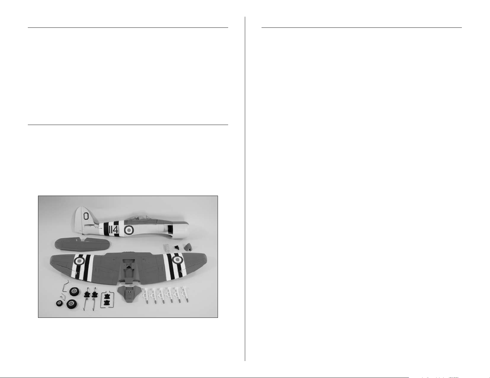
Contents of Kit/Parts Layout
Large Parts:
EFL6055 Cowling
EFL6059 Spinner
EFL6060 Retract Set
EFL6061 Straight Wire Struts for Retracts
EFL6062 Bent Wire Struts for Fixed Gear
EFL6063 Fixed Landing Gear Set
You will need a minimum 3-channel transmitter, crystals, receiver,
and three sub-micro servos. You can choose to purchase a
complete radio system. If you are using an existing transmitter,
just purchase the other required equipment separately. We
™
recommend the crystal-free, interference-free Spektrum
®
2.4GHz DSM
we recommend the E-flite
6-channel system. If using your own transmitter,
®
S75 Sub-Micro Servos.
DX6i
If you own the Spektrum DX6i radio, just add the AR6100E
™
DSM2
6-channel receiver and three (to six) of our E-flite S75
Sub-Micro Servos.
Complete Radio System
SPM6600 DX6i DSM 6CH system
Or Purchase Separately
JRPR720UL UltraLite 7-Channel ScanSelect
™
FM Receiver (72MHz)
JRP790UL UltraLite 7-Channel ScanSelect
PCM Receiver (72MHz)
Or
SPMAR6100E AR6100E DSM2 6-Channel Receiver
UltraLite (for DX6i on DX7)
And
EFLRS75 7.5-Gram Sub-Micro Servo (3–6)
EFLREX6L 6-inch Servo Extension, Lightweight (3)
EFLREX9L 9-inch Servo Extension, Lightweight (2)
(Optional Retracts)
EFLRYH3 3-inch Y-Harness, Lightweight
(2 required without computer radio)
Spektrum is used with permission of
Bachmann Industries, Inc.
3E-flite Hawker Sea Fury 400 ARF Assembly Manual
Page 4

Important Information About
Required Tools and Adhesives
Motor Selection
We recommend the E-flite Park 450 Brushless Outrunner
Motor, 890Kv (EFLM1400) for sport performance or the E-flite
Park 480 Brushless Outrunner Motor, 1020Kv (EFLM1505) for
maximum performance.
Sport Brushless Outrunner Setup
EFLM1400 Park 450 Brushless Outrunner Motor,
890Kv
EFLA1025 25A Pro Brushless ESC with 4 servos or
less or 40A Pro Switch-Mode BEC Brushless
ESC (EFLA1040) with 5+ servos
EFLB21003S E-flite 3S 11.1V 2100mAh 20C Li-Po or
Thunder Power 3S 11.1V 2200mAh 25C
eXtreme V2 Li-Po (THP22003SXV)
EFLAEC311 EC3 Extension Lead w/6" Wire, 16GA
High Power Brushless Outrunner Setup
EFLM1505 Park 480 Brushless Outrunner Motor,
1020Kv
EFLA1025 25A Pro Brushless ESC with 4 servos or
less or 40A Pro Switch-Mode BEC Brushless
ESC (EFLA1040) with 5+ servos
EFLB21003S E-flite 3S 11.1V 2100mAh 20C Li-Po or
Thunder Power 3S 11.1V 2200mAh 25C
eXtreme V2 Li-Po (THP22003SXV)
EFLAEC311 EC3 Extension Lead w/6" Wire, 16GA
Tools & Equipment
EFLA250 Park Flyer Tool Assortment, 5-piece
Or Purchase Separately
EFLA257 Screwdriver, #1 and #2 Phillips
(or included with EFLA250)
Pin drill
Drill bit: 1/16-inch (1.5mm), 1/8-inch (3mm)
Razor saw
Hex wrench: 1.5mm
Felt-tipped pen
Hobby knife w/new #11 blades
Phillips screwdriver: #00, #0, #1
Ruler
Sandpaper
Foam-safe CA
Optional Accessories
EFLA110 Power Meter
EFLC3005 Celectra
EFLC505 Intelligent 1- to 5-Cell Balancing Charger
4 E-flite Hawker Sea Fury 400 ARF Assembly Manual
™
1- to 3-Cell Li-Po Charger
Page 5

Notes Regarding Servos and ESC
Warranty Information
WARNING: Use of servos other than those we recommend may
overload the BEC of the recommended Electronic Speed Control
(ESC). We suggest the use of only the servos we recommend
when utilizing the recommended ESC’s BEC, or the use of a
separate BEC (like the UBEC) or receiver battery pack when
using other servos.
Note on Lithium Polymer Batteries
Lithium Polymer batteries are significantly more
volatile than alkaline or Ni-Cd/Ni-MH batteries used
in RC applications. All manufacturer’s instructions
and warnings must be followed closely. Mishandling
of Li-Po batteries can result in fire. Always follow the
manufacturer’s instructions when disposing of Lithium
Polymer batteries.
Warning
An RC aircraft is not a toy! If misused, it can cause serious
bodily harm and damage to property. Fly only in open areas,
preferably at AMA (Academy of Model Aeronautics) approved
flying sites, following all instructions included with your radio.
Keep loose items that can get entangled in the propeller away
from the prop, including loose clothing, or other objects such as
pencils and screwdrivers. Especially keep your hands away from
the propeller.
Warranty Period
Horizon Hobby, Inc., (Horizon) warranties that the Products purchased
(the “Product”) will be free from defects in materials and workmanship
at the date of purchase by the Purchaser.
Limited Warranty
(a) This warranty is limited to the original Purchaser ("Purchaser") and
is not transferable. REPAIR OR REPLACEMENT AS PROVIDED UNDER
THIS WARRANTY IS THE EXCLUSIVE REMEDY OF THE PURCHASER.
This warranty covers only those Products purchased from an
authorized Horizon dealer. Third party transactions are not covered
by this warranty. Proof of purchase is required for warranty claims.
Further, Horizon reserves the right to change or modify this warranty
without notice and disclaims all other warranties, express or implied.
(b) Limitations- HORIZON MAKES NO WARRANTY OR
REPRESENTATION, EXPRESS OR IMPLIED, ABOUT NONINFRINGEMENT, MERCHANTABILITY OR FITNESS FOR A
PARTICULAR PURPOSE OF THE PRODUCT. THE PURCHASER
ACKNOWLEDGES THAT THEY ALONE HAVE DETERMINED THAT
THE PRODUCT WILL SUITABLY MEET THE REQUIREMENTS OF THE
PURCHASER’S INTENDED USE.
(c) Purchaser Remedy- Horizon's sole obligation hereunder
shall be that Horizon will, at its option, (i) repair or (ii) replace, any
Product determined by Horizon to be defective. In the event of a
defect, these are the Purchaser's exclusive remedies. Horizon reserves
the right to inspect any and all equipment involved in a warranty
claim. Repair or replacement decisions are at the sole discretion of
Horizon. This warranty does not cover cosmetic damage or damage
due to acts of God, accident, misuse, abuse, negligence, commercial
use, or modification of or to any part of the Product. This warranty
does not cover damage due to improper installation, operation,
maintenance, or attempted repair by anyone other than Horizon.
Return of any goods by Purchaser must be approved in writing by
Horizon before shipment.
5E-flite Hawker Sea Fury 400 ARF Assembly Manual
Page 6

Damage Limits
Questions, Assistance, and Repairs
HORIZON SHALL NOT BE LIABLE FOR SPECIAL, INDIRECT OR
CONSEQUENTIAL DAMAGES, LOSS OF PROFITS OR PRODUCTION
OR COMMERCIAL LOSS IN ANY WAY CONNECTED WITH THE
PRODUCT, WHETHER SUCH CLAIM IS BASED IN CONTRACT,
WARRANTY, NEGLIGENCE, OR STRICT LIABILITY. Further, in no
event shall the liability of Horizon exceed the individual price of the
Product on which liability is asserted. As Horizon has no control over
use, setup, final assembly, modification or misuse, no liability shall be
assumed nor accepted for any resulting damage or injury. By the act
of use, setup or assembly, the user accepts all resulting liability.
If you as the Purchaser or user are not prepared to accept the liability
associated with the use of this Product, you are advised to return this
Product immediately in new and unused condition to the place of
purchase.
Law: These Terms are governed by Illinois law (without regard to
conflict of law principals).
Safety Precautions
This is a sophisticated hobby Product and not a toy. It must be
operated with caution and common sense and requires some basic
mechanical ability. Failure to operate this Product in a safe and
responsible manner could result in injury or damage to the Product or
other property. This Product is not intended for use by children without
direct adult supervision. The Product manual contains instructions for
safety, operation and maintenance. It is essential to read and follow
all the instructions and warnings in the manual, prior to assembly,
setup or use, in order to operate correctly and avoid damage or
injury.
Your local hobby store and/or place of purchase cannot provide
warranty support or repair. Once assembly, setup or use of the
Product has been started, you must contact Horizon directly. This will
enable Horizon to better answer your questions and service you in the
event that you may need any assistance. For questions or assistance,
please direct your email to productsupport@horizonhobby.com, or call
877.504.0233 toll free to speak to a service technician.
Inspection or Repairs
If this Product needs to be inspected or repaired, please call for a
Return Merchandise Authorization (RMA). Pack the Product securely
using a shipping carton. Please note that original boxes may be
included, but are not designed to withstand the rigors of shipping
without additional protection. Ship via a carrier that provides tracking
and insurance for lost or damaged parcels, as Horizon is not
responsible for merchandise until it arrives and is accepted
at our facility. A Service Repair Request is available at www.
horizonhobby.com on the “Support” tab. If you do not have internet
access, please include a letter with your complete name, street
address, email address and phone number where you can be reached
during business days, your RMA number, a list of the included items,
method of payment for any non-warranty expenses and a brief
summary of the problem. Your original sales receipt must also be
included for warranty consideration. Be sure your name, address, and
RMA number are clearly written on the outside of the shipping carton.
Warranty Inspection and Repairs
To receive warranty service, you must include your original
sales receipt verifying the proof-of-purchase date. Provided warranty
conditions have been met, your Product will be repaired or replaced
free of charge. Repair or replacement decisions are at the sole
discretion of Horizon Hobby.
6 E-flite Hawker Sea Fury 400 ARF Assembly Manual
Page 7

Non-Warranty Repairs
Should your repair not be covered by warranty the repair
will be completed and payment will be required without
notification or estimate of the expense unless the expense
exceeds 50% of the retail purchase cost.
item for repair you are agreeing to payment of the repair without
notification. Repair estimates are available upon request. You must
include this request with your repair. Non-warranty repair estimates
will be billed a minimum of ½ hour of labor. In addition you will be
billed for return freight. Please advise us of your preferred method
of payment. Horizon accepts money orders and cashiers checks, as
well as Visa, MasterCard, American Express, and Discover cards.
If you choose to pay by credit card, please include your credit card
number and expiration date. Any repair left unpaid or unclaimed
after 90 days will be considered abandoned and will be disposed of
accordingly.
Please note: non-warranty repair is only available
on electronics and model engines.
Electronics and engines requiring inspection or repair should be
shipped to the following address:
Horizon Service Center
4105 Fieldstone Road
Champaign, Illinois 61822
By submitting the
Safety, Precautions, and Warnings
As the user of this product, you are solely responsible for
operating it in a manner that does not endanger yourself
and others or result in damage to the product or the property
of others.
Carefully follow the directions and warnings for this and any
optional support equipment (chargers, rechargeable battery
packs, etc.) that you use.
This model is controlled by a radio signal that is subject to
interference from many sources outside your control. This
interference can cause momentary loss of control so it is
necessary to always keep a safe distance in all directions
around your model, as this margin will help to avoid collisions
or injury.
• Always operate your model in an open area away from cars,
traffic, or people.
• Avoid operating your model in the street where injury or
damage can occur.
• Never operate the model out into the street or populated
areas for any reason.
All other Products requiring warranty inspection or repair should be
shipped to the following address:
Horizon Product Support
4105 Fieldstone Road
Champaign, Illinois 61822
Please call 877-504-0233 with any questions or concerns
regarding this product or warranty.
• Never operate your model with low transmitter batteries.
• Carefully follow the directions and warnings for this and any
optional support equipment (chargers, rechargeable battery
packs, etc.) that you use.
• Keep all chemicals, small parts and anything electrical out of
the reach of children.
• Moisture causes damage to electronics. Avoid water exposure
to all equipment not specifically designed and protected for
this purpose.
7E-flite Hawker Sea Fury 400 ARF Assembly Manual
Page 8

Fixed Gear Installation
Required Parts
Fixed main gear wire (right and left)
Landing gear block (2) 2mm x 10mm shoulder screw (4)
3mm x 6mm countersunk sheet metal screw (8)
Required Tools and Adhesives
Phillips screwdriver: #0, #1
1. Insert the landing gear into the landing gear block.
2. Use two 2mm x 10mm shoulder screws and a #0
Phillips screwdriver to secure the landing gear to the
landing gear block.
3. Repeat Steps 1 and 2 to assemble the second landing
gear. (Make one left and one right)
8 E-flite Hawker Sea Fury 400 ARF Assembly Manual
Page 9
4. Secure the landing gear assembly in the wing using a
#1 Phillips screwdriver and four 3mm x 6mm countersunk
sheet metal screws per assembly. The strut is positioned
toward the wing tip and is angled toward the leading
edge when installed correctly.
Retract Installation
Required Parts
Servo (2) Retract linkage (2)
Double-sided tape (2 pcs)
Retract assembly (right and left)
3mm x 6mm countersunk sheet metal screw (8)
Required Tools and Adhesives
Phillips screwdriver: #0, #1 Hobby knife
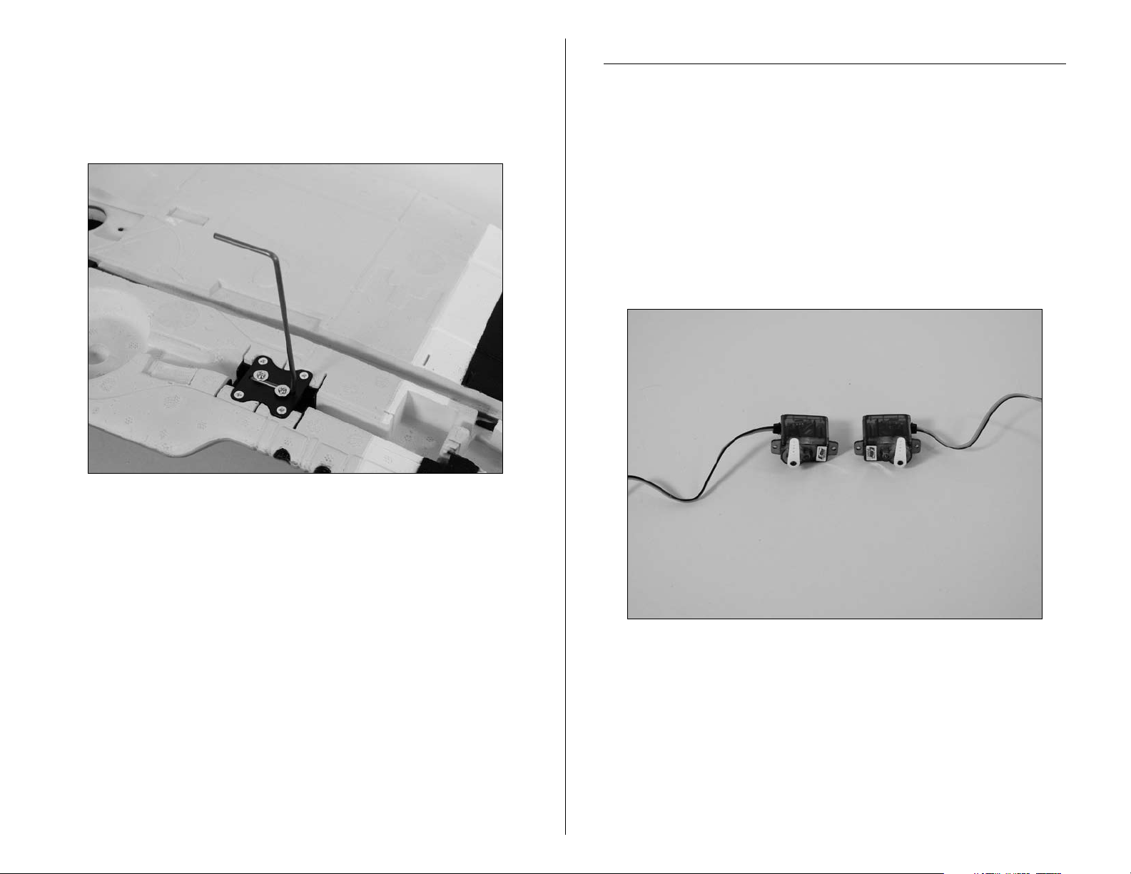
1. Prepare the retract servos by installing the servo arms
on the servos.
Note: The servos are shown with the servo arms
centered. Make sure to position the servo horn so they
travel equally from this center position or your retracts
may not operate correctly.
9E-flite Hawker Sea Fury 400 ARF Assembly Manual
Page 10

2. Apply a piece of double-sided tape onto each servo,
on the side opposite the servo arm.
3. Connect the retract linkage to the retract
actuator arm.
4. Secure the retract assembly in the wing using a #1
Phillips screwdriver and four 3mm x 6mm countersunk
sheet metal screws per assembly.
10 E-flite Hawker Sea Fury 400 ARF Assembly Manual
Page 11
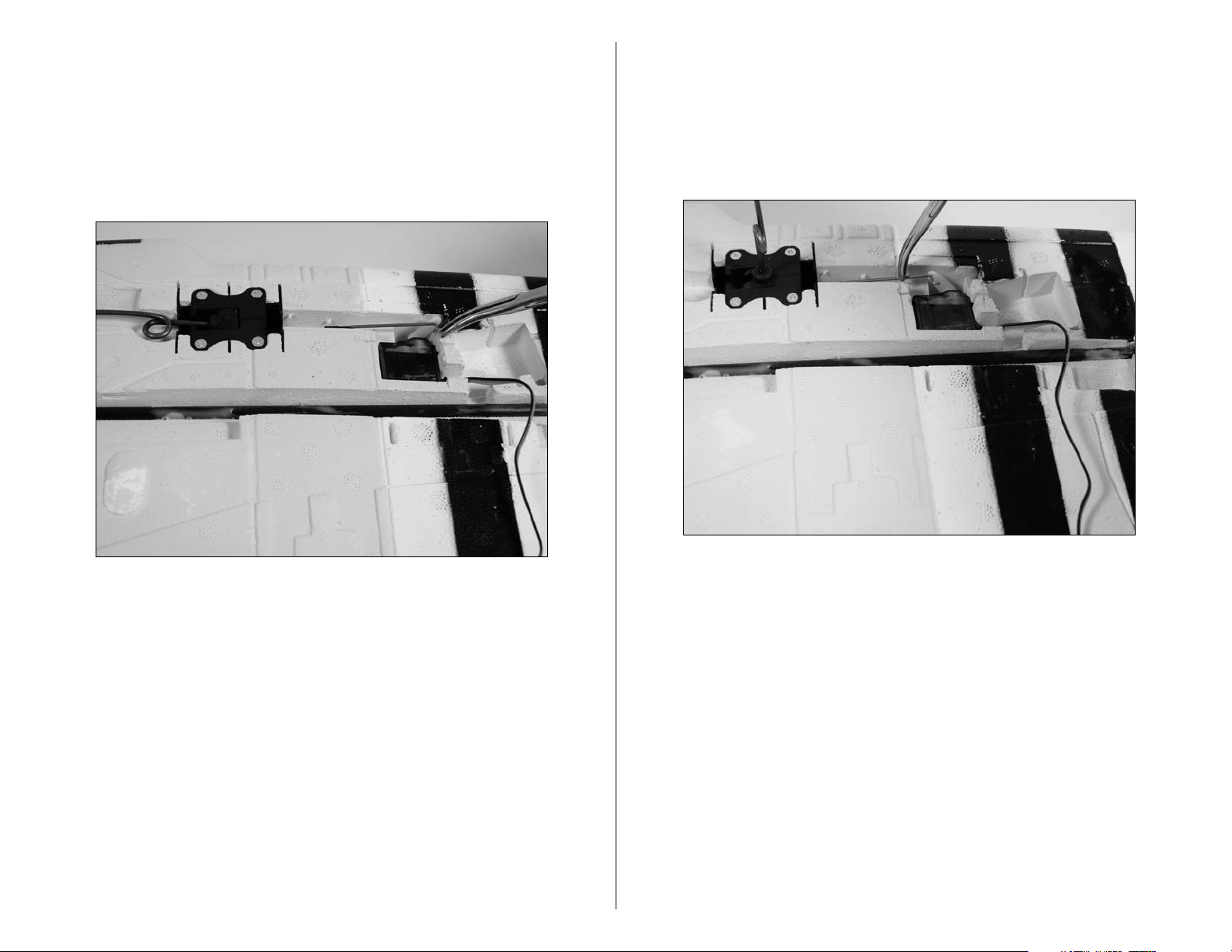
5. Place the retract in the Up position and insert the
retract servo in the pocket. Do not connect the linkage
to the retract servo at this time. Use the radio to move
the servo arm to the Up position. Hold the linkage to the
arm to make sure the linkage aligns with the servo arm.
Adjust the end point at the radio to align the arm with
the linkage.
6. Place the retract in the down position and use the
radio to move the servo to the down position. Do not
connect the linkage to the retract servo at this time.
Hold the linkage to the arm to make sure the linkage
aligns with the servo arm. Adjust the end point at the
radio to align the arm with the linkage.
11E-flite Hawker Sea Fury 400 ARF Assembly Manual
Page 12

7. Remove the servos once the end points have been
adjusted and attach the linkage to the servo. Use a
hobby knife to enlarge the hole in the servo arm if
needed. Peel the backing tape off of the servo and mount
it in position.
Aileron Servo Installation
Required Parts
Aileron linkage w/clevis and keeper (2)
Wing extension
Wing Servo (2)
Double-sided tape (2 pcs)
6-inch (152mm) extension
9-inch (228mm) extension (2) (for optional retracts)
Required Tools and Adhesives
Hobby knife Foam-safe CA
Phillips screwdriver: #0
1. Locate the wing extension and test fit it to the rear of
the wing. Use foam-safe CA to glue the extension directly
to the wing.
Note: If you are using a 6-channel or more computer
radio you can use a separate channel for each of the
retract servos. Using two channels and mixing them
together will give you the option for independent
adjustment of the travel adjustment of each servo. If you
are not using a computer radio with mixing you will need
to use a reversing Y-harness (EXRA320) instead.
8. Repeat Steps 2 through 7 to install the remaining
retract and servo.
12 E-flite Hawker Sea Fury 400 ARF Assembly Manual
Page 13

2. Prepare the aileron servos by installing the servo arms
on the servos. Use your radio to center these servos at
this time.
3. Apply a piece of double-sided tape onto each servo,
on the side opposite the servo arm.
4. Remove the backing from the double-sided tape.
Position the servo so the arm is facing toward the aileron
and the outboard side off the wing. Press each aileron
servo into the openings in the wing.
13E-flite Hawker Sea Fury 400 ARF Assembly Manual
Page 14

5. Connect a 6-inch (152mm) extension to each aileron
servo lead. If you have opted to install retracts, attach
a 9-inch (228mm) extension to each retract servo lead.
Use string to secure the extension(s) so they do not
unplug accidentally.
7. Remove the backing from the double-sided tape on
the wing cover.
6. Route the leads for the aileron (and retract) servo(s)
along the channel in the wing. The extension(s) then
8. Carefully position the wing cover on the bottom of the
wing. Make sure to align the cover when positioning it.
pass to the top of the wing through the hole in the
center of the wing.
14 E-flite Hawker Sea Fury 400 ARF Assembly Manual
Page 15

9. Use a hobby knife to enlarge the outer hole on the
aileron servo arm to accept the aileron linkage.
10. Insert the Z-bend on the aileron linkage into the outer
hole of the aileron servo horn.
11. Connect the clevis of the aileron linkage to the
aileron control horn. With the radio on, it may be
necessary to adjust the length of the linkage so the
aileron is centered.
12. Repeat Steps 9 through 11 to connect the remaining
aileron linkage.
15E-flite Hawker Sea Fury 400 ARF Assembly Manual
Page 16

Main Wheel Installation
Required Parts
Wheel spacer (2) Main wheel (2)
Wheel axle cap (2)
Required Tools and Adhesives
Foam-safe CA
Note: The wheel installation is the same for both fixed
gear and retracts.
1. Slide the wheel spacer onto the landing gear axle.
2. Slide the wheel onto the landing gear axle.
3. Secure the wheel using the wheel axle cap and
foam-safe CA. Use care not to get CA between the
landing gear and wheel, which will prevent the wheel
from rolling.
4. Repeat Steps 1 through 3 to install the
remaining wheel.
16 E-flite Hawker Sea Fury 400 ARF Assembly Manual
Page 17

Motor and Cowling Installation
Park 450
Park 480
Required Parts
Motor mount 6-inch (152mm) servo extension
Electronic speed control 1.5mm x 10mm self-tapping screw
Propeller 6-inch (152mm) battery extension
Motor w/accessories Spinner backplate
Spinner cone Spinner washer
3mm x 10mm machine screw (4)
1/8-inch (3mm) spacer (4)
Required Tools and Adhesives
Razor saw Phillips screwdriver: #00, #1
1. Attach the Park 450 motor to the mount using a
#1 Phillips screwdriver and four 3mm x 10mm machine
screws and the four 1/8-inch (3mm) spacers as shown..
Use threadlock on the screws to prevent the vibrations of
the motor from loosening the screws.
Note: When installing the Park 480 motor, use a #1
Phillips screwdriver, four 3mm x 10mm machine screws
and the four 1/8-inch (3mm) spacers as shown. Use
threadlock on the screws to prevent the vibrations of the
motor from loosening the screws.
2. Use a razor saw to cut the length of the motor
mounting stick to 15/16-inch (24mm) as shown below.
17E-flite Hawker Sea Fury 400 ARF Assembly Manual
Page 18

3. Lift the hatch from the fuselage as shown.
4. Remove the battery stop from the inside of the fuselage
by sliding it rearward and out of the fuselage.
Important Information About Your Brushless ESC
Make sure your ESC brake is programmed to Off. Also,
be sure to use an ESC with the proper low-voltage cutoff
and have it set correctly for the batteries you are using.
Note: Never check the motor rotation on the bench
with the propeller installed. The plane could move and
cause serious injury. Always check the motor without the
propeller to avoid injury.
5. Connect the battery and servo lead extensions to the
speed control. Secure them using string to prevent them
from being unplugged inside the fuselage.
18 E-flite Hawker Sea Fury 400 ARF Assembly Manual
Page 19

6. Pass the battery and servo extensions into the lower
hole in the fuselage and into the main radio compartment
as shown below.
7. Secure the speed control inside the motor compartment
using double-sided tape.
Note: If using the the Eflite 40-amp speed control, we
recommend that you tape the switch in the On position
and mount it inside the motor compartment or extend the
leads so that it will reach the radio compartment.
8. Connect the leads from the motor to the speed control.
Slide the motor mount onto the motor stick.
19E-flite Hawker Sea Fury 400 ARF Assembly Manual
Page 20

9. Secure the motor mount using the 1.5mm x 10mm
Park 480
Park 450
self-tapping screw and a #00 Phillips screwdriver. Secure
the wires inside the motor compartment so they will not
interfere with the operation of the motor.
10. Check the operation of the motor at this time. It
should rotate counterclockwise when viewed from the
front of the aircraft. If not, follow the instructions provided
with your speed control to correct the situation.
11. Remove the backing from the double-sided tape on
both sides of the fuselage.
20 E-flite Hawker Sea Fury 400 ARF Assembly Manual
Page 21

12. Slide the cowling onto the fuselage. Press the cowling
against the tape to secure it in position.
13. Slide the propeller adapter into the propeller.
Important Information About Your Propeller
It is also very important to check to be sure the
propeller is balanced before installing onto the shaft. An
unbalanced propeller may strip the gears or cause poor
flight characteristics.
Note: If it is necessary to enlarge the hole in the
propeller or the spinner, make sure to check the balance
of each afterwards.
15. The spinner backplate is then placed on the adapter.
21E-flite Hawker Sea Fury 400 ARF Assembly Manual
Page 22

14. Next, slide the supplied washer onto the adapter.
16. Install the adapter nut, but do not tighten it at
this time.
17. Place the spinner assembly on the motor shaft.
Check that the positioning of the assembly will allow the
backplate and propeller to spin without rubbing on the
cowling. Tighten the adapter nut once all is well.
18. Snap the spinner cone onto the spinner backplate to
complete the motor assembly.
22 E-flite Hawker Sea Fury 400 ARF Assembly Manual
Page 23

Radio Installation - Fuselage
Required Parts
Hook and loop tape Receiver
Y-harness (ailerons)
Servo (two required if using rudder control)
Required Tools and Adhesives
Phillips screwdriver: #0 Pin drill
Drill bit: 1/16-inch (1.5mm)
1. Mount the rudder and elevator servos in the fuselage
using a pin drill and 1/16-inch (1.5mm) drill bit and the
hardware provided with the servo.
2. Plug the leads from the servos and speed control to
the appropriate outputs on the receiver. Also connect the
harness for the aileron servo to the receiver.
3. Use double-sided tape to secure the receiver in the
fuselage as shown.
Note: If you have elected not to install the optional
rudder, you will not need to install the rudder servo.
23E-flite Hawker Sea Fury 400 ARF Assembly Manual
Page 24

Tail Gear Installation - Fixed Rudder
Required Parts
Tail wheel collar w/setscrew Tail wheel
Wheel spacer Wheel axle cap
Fixed tail gear wire
Required Tools and Adhesives
Hex wrench: 1.5mm Foam-safe CA
Note: If you will be installing the operational rudder, skip
to the next section of the manual.
1. Slide the tail wheel collar onto the tail wheel bearing.
Align the setscrew with the notch in the bearing.
2. Slide the fixed gear tail wire into the bearing, then use
a 1.5mm hex wrench to tighten the setscrew. The wire
has a flat area for the setscrew to be tightened onto.
3. Slide the wheel spacer onto the tail gear wire.
24 E-flite Hawker Sea Fury 400 ARF Assembly Manual
Page 25

4. Slide the tail wheel onto the tail gear wire.
Optional Operable Rudder
Required Parts
Control horn Control horn backplate
2mm x 10mm sheet metal screw (2)
Operational tail gear wire Tail wheel
Wheel spacer Wheel axle cap
Required Tools and Adhesives
Hobby knife Foam-safe CA
Drill bit: 1/8-inch (3mm) Pin drill
Felt-tipped pen Sandpaper
Note: Although the optional rudder can be installed after
the stabilizer, it is much easier to do so before installing
the stabilizer. The photos show the stabilizer installed
for reference, even though the actual installation will be
covered later in the manual.
5. Secure the wheel using the wheel axle cap and
foam-safe CA. Use care not to get CA between the
tail gear wire and wheel, which will prevent the
wheel from rolling.
1. Use a hobby knife to cut the rudder from the fin. Cut
as close to the fin as possible for the best results.
25E-flite Hawker Sea Fury 400 ARF Assembly Manual
Page 26

2. Use sandpaper to remove any irregularities from the
fin and rudder.
3. Mount the control horn to the rudder as shown using
two 2mm x 10mm sheet metal screws, control horn
backplate and a #1 Phillips screwdriver.
4. Cut slots in the rudder for the three rudder hinges. Use
foam-safe CA to glue the hinges half-way into the rudder
as shown.
26 E-flite Hawker Sea Fury 400 ARF Assembly Manual
Page 27

5. Use a pin drill and 1/8-inch (3mm) drill bit to drill a
hole for the tail gear wire in the rudder.
7. Use a hobby knife to cut the slots for the rudder hinges
in the fin.
6. Hold the rudder against the fin and use a felt-tipped
pen to transfer the location of the hinges to the find.
8. Slide the operational tail gear wire through the tail
gear bushing as shown.
27E-flite Hawker Sea Fury 400 ARF Assembly Manual
Page 28

9. Test fit the rudder to the fin. Once satisfied with the
fit, use foam-safe CA on the hinges and tail gear wire to
secure the rudder to the fin. Make sure not to get CA in
the tail gear assembly.
11. Slide the tail wheel onto the tail gear wire.
12. Secure the wheel using the wheel axle cap and
foam-safe CA. Use care not to get CA between the
tail gear wire and wheel, which will prevent the
wheel from rolling.
10. Slide the wheel spacer onto the tail gear wire.
28 E-flite Hawker Sea Fury 400 ARF Assembly Manual
Page 29

Stabilizer/Elevator Installation
Required Parts
Fuselage assembly Stabilizer assembly
7
13
/
-inch (335mm) pushrod w/clevis
32
9
/
13
Required Tools and Adhesives
Foam-safe CA
1. Remove the elevators and elevator joiner wire
-inch (345mm) pushrod w/clevis (for optional rudder)
16
from the stabilizer.
2. Place the elevator joiner wire in the slot in the fuselage
for the stabilizer.
29E-flite Hawker Sea Fury 400 ARF Assembly Manual
Page 30

3. Slide the stabilizer into the slot in the fuselage.
Measure the distance from each stabilizer tip to each
wing tip. The measurements must be equal. Adjust
the position of the stabilizer if necessary to correct for
the alignment.
4. After aligning the stabilizer to the wing, use foam-safe
CA. Double check the alignment one last time before the
CA fully cures. Once the CA cures, snap the joiner wire
back into the bracket at the trailing edge of the stabilizer.
5. Apply foam-safe CA to each side of the hinge, as well
3. Stand back and view the model from the rear. The
as to the elevator joiner wire.
wing and stabilizer must be parallel to each other. Lightly
sand the opening in the fuselage for the stabilizer to
correct for any alignment issues.
30 E-flite Hawker Sea Fury 400 ARF Assembly Manual
Page 31

6. Attach both elevator halves to the stabilizer. Remember
to work quickly to avoid having the CA cure before the
elevator installation is complete.
7. Remove the clevis from the 13
pushrod. Slide the pushrod into the preinstalled tube in
the fuselage.
7
/
-inch (335mm)
32
8. Connect the bend in the pushrod to the elevator servo
horn. Position the horn so the angle between it and the
pushrod wire is 90 degrees. Secure the horn to the servo.
31E-flite Hawker Sea Fury 400 ARF Assembly Manual
Page 32

9. Thread the clevis back on the pushrod wire. Connect
the clevis to the elevator control horn.
10. With the radio system on, adjust the position of the
clevis so the elevator is parallel to the stabilizer.
Linkage Installation for Optional Rudder
The next three steps cover the installation of the linkage
for the optional rudder. Skip to the next section if you are
not using the optional rudder.
9
/
11. Remove the clevis from the 13
pushrod. Slide the pushrod into the preinstalled tube
in the fuselage. Connect the bend in the pushrod to
the rudder servo horn. Position the horn so the angle
between it and the pushrod wire is 90 degrees. Secure
the horn to the servo.
-inch (345mm)
16
32 E-flite Hawker Sea Fury 400 ARF Assembly Manual
Page 33

12. Thread the clevis back on the pushrod wire. Connect
the clevis to the rudder control horn.
13. With the radio system on, adjust the position of the
clevis so the rudder is parallel to the fin.
Final Assembly
Required Parts
Rocket (6) 3mm x 45mm machine screw (2)
Battery stop Canopy
Required Tools and Adhesives
Phillips screwdriver: #1
1. Connect the aileron servo extensions to the aileron
harness. The retract leads will pass into the fuselage and
connect to the receiver with a Y-harness or plug directly
into the receiver if using separate channels.
33E-flite Hawker Sea Fury 400 ARF Assembly Manual
Page 34

2. Secure the wing using two 3mm x 45mm machine
screws in the center of the wing, and the preinstalled
screw at the trailing edge of the wing. Use a #1 Phillips
screwdriver to tighten the screws.
3. Slide the motor battery into the fuselage. Slide the
battery as far forward as possible.
4. Connect the motor battery to the speed control.
Note: Make sure to be clear of the propeller when
connecting the battery in case the motor starts
unexpectedly.
34 E-flite Hawker Sea Fury 400 ARF Assembly Manual
Page 35

5. Slide the battery stop back into the fuselage. If it
is not fully in position, the canopy will not fit back onto
the fuselage.
7. The rockets are installed by pressing them into
the precut slots in the wing cover and into the slots
in the wing.
6. Place the canopy back onto the fuselage.
35E-flite Hawker Sea Fury 400 ARF Assembly Manual
Page 36

Control Throws
1. Turn on the transmitter and receiver of your Hawker Sea
Fury. Check the movement of the rudder using the transmitter.
When the stick is moved right, the rudder should also move
right. Reverse the direction of the servo at the transmitter if
necessary.
2. Check the movement of the elevator with the radio system.
Moving the elevator stick down will make the airplane
elevator move up.
3. Check the movement of the ailerons with the radio system.
Moving the aileron stick right will make the right aileron
move up and the left aileron move down.
4. Use a ruler to adjust the throw of the elevator, ailerons
and rudder. Adjust the position of the pushrod at the control
horn to achieve the following measurements when moving the
sticks to their endpoints.
Note: Measurements are taken at the widest point on
the surface.
Once all the control throws have been set, make sure to slide
the clevis retainers over the clevises to prevent them from
opening accidentally.
Ailerons D/R Expo
Low Rate: 5/16-inch (8mm) (Up/Down) 60 10%
High Rate: 1/2-inch (13mm) (Up/Down) 100 15%
Elevator
Low Rate: 5/16-inch (8mm) (Up/Down) 60 15%
High Rate: 7/16-inch (11mm) (Up/Down) 100 20%
Rudder (optional)
Low Rate: 1/2-inch (13mm) (Right/Left) 60 10%
High Rate: 13/16-inch (20mm) (Right/Left) 100 20%
These are general guidelines measured from our own flight tests.
You can experiment with higher rates to match your preferred
style of flying.
36 E-flite Hawker Sea Fury 400 ARF Assembly Manual
Page 37

Center of Gravity
Range Test Your Radio
An important part of preparing the aircraft for flight is properly
balancing the model.
Caution: Do not inadvertently skip this step!
Please balance your model inverted with the battery installed.
With the model inverted, lift the model at the Center of Gravity
(CG) marks molded into the wing using your fingertips, or use
a commercially available balancing stand. The model will rest
level or slightly nose down when balanced correctly. Add the
clay weight supplied to the nose or tail if necessary to achieve
the correct CG.
1. Please consult your radio instructions for complete range
testing instructions.
2. Double-check that all controls (aileron, elevator, rudder
and throttle) move in the correct direction.
3. Be sure that your transmitter batteries are fully charged,
per the instructions included with your radio.
Instructions for Disposal of WEEE by
Users in the European Union
This product must not be disposed of with other waste. Instead,
it is the user’s responsibility to dispose of their waste equipment
by handing it over to a designated collection point for the
recycling of waste electrical and electronic equipment. The
separate collection and recycling of your waste equipment at
the time of disposal will help to conserve natural resources and
ensure that it is recycled in a manner that protects human health
and the environment. For more information about where you
can drop off your waste equipment for recycling, please contact
your local city office, your household waste disposal service or
where you purchased the product.
After the first flights, the CG position can be adjusted for your
personal preference.
37E-flite Hawker Sea Fury 400 ARF Assembly Manual
Page 38

Preflight
Flying Your Hawker Sea Fury ARF
Check Your Radio
Before going to the field, be sure that your batteries are fully
charged per the instructions included with your radio. Charge
both the transmitter and receiver pack for your airplane. Use
the recommended charger supplied with your particular radio
system, following the instructions provided with the radio. In
most cases, the radio should be charged the night before going
out flying.
Before each flying session, be sure to range check your radio.
See your radio manual for the recommended range and
instructions for your radio system. Each radio manufacturer
specifies different procedures for their radio systems. Next, start
the motor. With the model securely anchored, check the range
again. The range test should not be significantly affected. If it is,
don’t attempt to fly! Have your radio equipment checked out by
the manufacturer.
Note: Keep loose items that can get entangled in
the propeller away from the prop. These include
loose clothing, or other objects such as pencils and
screwdrivers. Especially keep your hands away from
the propeller.
Double-check that all controls (aileron, elevator, rudder and
throttle) move in the correct direction.
Check the radio installation and make sure all the control
surfaces are moving correctly (i.e. the correct direction and with
the recommended throws). Test run the motor and make sure
it transitions smoothly from off to full throttle and back. Also
ensure the engine is installed according to the manufacturer’s
instructions, and it will operate consistently.
Begin by placing the model on the ground. Check all control
throws and ensure everything is traveling in the right direction.
Move your idle trim up until the prop begins to spin; this will be
your flight idle. Taxi into position on the runway, facing into the
wind. Apply power slowly and steer with rudder. The tail will
come up very quickly. As you apply full throttle and come to
speed, apply a slight amount of up elevator and the Sea Fury
should lift off gently and begin to climb upwards. As you climb,
out release the elevator and maintain a gentle climb to about
100 feet of altitude.
Once at about 100 feet of altitude, trim the model for level
flight at 5/8 throttle. You will find the Sea Fury to be very gentle
on the control and feel quite light on the sticks. The model is
capable of all the basic aerobatic maneuvers; loops, rolls, stall
turns, inverted flight, etc.
If you have no roll issues with the model then you are ready to
set up for landing. We normally do a pass over the runway on
this pass. Turn into the downwind and manage the power at
about 1/2 throttle. As you turn to base leg, you may reduce the
throttle a bit and then when you turn final adjust the power to
maintain a shallow descent with the model. As you come down
to an altitude of about 8 feet over the runway, begin to level the
model out and as you get within 3 feet, you will begin to flare
for landing. The Sea Fury likes to be either landed on the mains
or three pointed on the gear in a full stall. The choice is yours.
We at E-flite hope you enjoy your Sea Fury as much as we
have. Happy landings!
Check all the control horns, servo horns, and clevises to make
sure they are secure and in good condition. Replace any items
that would be considered questionable. Failure of any of these
components in flight would mean the loss of your aircraft.
38 E-flite Hawker Sea Fury 400 ARF Assembly Manual
Page 39

2008 Official AMA National
Model Aircraft Safety Code
GENERAL
1) I will not fly my model aircraft in sanctioned events, air shows
or model flying demonstrations until it has been proven to be
airworthy by having been previously, successfully flight tested.
2) I will not fly my model higher than approximately 400 feet within 3
miles of an airport without notifying the airport operator. I will give
right-of-way and avoid flying in the proximity of full-scale aircraft.
Where necessary, an observer shall be utilized to supervise flying
to avoid having models fly in the proximity of full-scale aircraft.
3) Where established, I will abide by the safety rules for the flying
site I use, and I will not willfully or deliberately fly my models in a
careless, reckless and/or dangerous manner.
4) The maximum takeoff weight of a model is 55 pounds, except
models flown under Experimental Aircraft rules.
5) I will not fly my model unless it is identified with my name and
address or AMA number on or in the model. (This does not apply
to models while being flown indoors.)
6) I will not operate models with metal-bladed propellers or with
gaseous boosts, in which gases other than air enter their internal
combustion engine(s); nor will I operate models with extremely
hazardous fuels such as those containing tetranitromethane or
hydrazine.
RADIO CONTROL
1) I will have completed a successful radio equipment ground range
check before the first flight of a new or repaired model.
2) I will not fly my model aircraft in the presence of spectators until I
become a qualified flier, unless assisted by an experienced helper.
3) At all flying sites a straight or curved line(s) must be established
in front of which all flying takes place with the other side for
spectators. Only personnel involved with flying the aircraft are
allowed at or in front of the flight line. Intentional flying behind the
flight line is prohibited.
4) I will operate my model using only radio control frequencies
currently allowed by the Federal Communications Commission.
(Only properly licensed Amateurs are authorized to operate
equipment on Amateur Band frequencies.)
5) Flying sites separated by three miles or more are considered safe
from site-to-site interference, even when both sites use the same
frequencies. Any circumstances under three miles separation
require a frequency management arrangement, which may be
either an allocation of specific frequencies for each site or testing
to determine that freedom from interference exists. Allocation plans
or interference test reports shall be signed by the parties involved
and provided to AMA Headquarters.
Documents of agreement and reports may exist between (1) two
or more AMA Chartered Clubs, (2) AMA clubs and individual
AMA members not associated with AMA Clubs, or (3) two or
more individual AMA members.
6) For Combat, distance between combat engagement line
and spectator line will be 500 feet per cubic inch of engine
displacement. (Example: .40 engine = 200 feet.); electric motors
will be based on equivalent combustion engine size. Additional
safety requirements will be per the RC Combat section of the
current Competition Regulations.
7) At air shows or model flying demonstrations, a single straight line
must be established, one side of which is for flying, with the other
side for spectators.
8) With the exception of events flown under AMA Competition rules,
after launch, except for pilots or helpers being used, no powered
model may be flown closer than 25 feet to any person.
9) Under no circumstances may a pilot or other person touch a
powered model in flight.
39E-flite Hawker Sea Fury 400 ARF Assembly Manual
Page 40

12846
© 2008 Horizon Hobby, Inc.
4105 Fieldstone Road
Champaign, Illinois 61822
(877) 504-0233
horizonhobby.com
E-fliteRC.com
 Loading...