

Page 1

Instruction Manual
Bedienungsanleitung
Page 2
EN
NOTICE
All instructions, warranties and other collateral documents are subject to change at the sole discretion of Horizon Hobby, Inc. For up-to-date
product literature, visit horizonhobby.com and click on the support tab for this product.
Meaning of Special Language
The following terms are used throughout the product literature to indicate various levels of potential harm when operating this product:
NOTICE: Procedures, which if not properly followed, create a possibility of physical property damage AND a little or no possibility of injury.
CAUTION: Procedures, which if not properly followed, create the probability of physical property damage AND a possibility of serious injury.
WARNING: Procedures, which if not properly followed, create the probability of property damage, collateral damage, and serious injury OR
create a high probability of superficial injury..
Age Recommendation: Not for children under 14 years. This is not a toy.
WARNING: Read the ENTIRE instruction manual to become familiar with the features of the product before operating. Failure to operate the
product correctly can result in damage to the product, personal property and cause serious injury.
This is a sophisticated hobby product. It must be operated with caution and common sense and requires some basic mechanical ability. Failure to
operate this Product in a safe and responsible manner could result in injury or damage to the product or other property. This product is not intended for
use by children without direct adult supervision. Do not attempt disassembly, use with incompatible components or augment product in any way without the approval of Horizon Hobby, Inc. This manual contains instructions for safety, operation and maintenance. It is essential to read and follow all the
instructions and warnings in the manual, prior to assembly, setup or use, in order to operate correctly and avoid damage or serious injury.
FLIGHT
Fly only in open areas to ensure safety. It is recommended flying be done at AMA (Academy of Model Aeronautics) approved flying sites. Consult local
laws and ordinances before choosing a location to fly your aircraft.
INTAKE/FAN
Keep loose items that can get entangled in the fan away from the intake and exhaust, including loose clothing, or other objects such as pencils and
screwdrivers. Especially keep your hands away from the intake and exhaust as injury can occur.
BATTERY WARNINGS
The Battery Charger included with your aircraft is designed to safely
charge the Li-Po battery.
CAUTION: All instructions and warnings must be followed exactly.
Mishandling of Li-Po batteries can result in a fire, personal injury, and/or
property damage.
• By handling, charging or using the included Li-Po battery, you assume
all risks associated with lithium batteries.
• If at any time the battery begins to balloon or swell, discontinue use
immediately. If charging or discharging, discontinue and disconnect.
Continuing to use, charge or discharge a battery that is ballooning or
swelling can result in fire.
• Always store the battery at room temperature in a dry area for best
results.
• Always transport or temporarily store the battery in a temperature range
of 40–120º F. Do not store battery or model in a car or direct sunlight. If
stored in a hot car, the battery can be damaged or even catch fire.
NEVER USE A Ni-Cd OR Ni-MH CHARGER. Failure to charge the battery
with a compatible charger may cause fire resulting in personal injury
and/or property damage.
• Never discharge Li-Po cells to below 3V under load.
• Never cover warning labels with hook and loop strips.
• Never leave charging batteries unattended.
• Never charge batteries outside safe temperature range.
• Never charge damaged batteries.
SAFETY PRECAUTIONS
• Check all control surfaces prior to each takeoff.
• Do not fly your model near spectators, parking areas or any other area
that could result in injury to people or damage of property.
• Do not fly during adverse weather conditions. Poor visibility can cause
disorientation and loss of control of your aircraft. Strong winds can
cause similar problems.
• Do not take chances. If at any time during flight you observe any erratic
or abnormal operation, land immediately and do not resume flight until
the cause of the problem has been ascertained and corrected. Safety
can never be taken lightly.
• Do not fly near power lines.
2
Page 3

EN
TABLE OF CONTENTS
Introduction ...............................................3
Specifications ..............................................3
Using the Manual ...........................................3
Contents of Kit/Parts Layout ...................................4
Covering Colors ............................................4
Hardware/Accessory Sizes ....................................4
Recommended Radio Equipment ...............................4
Motor Setup ...............................................4
Optional Accessories .........................................4
Optional Retracts ...........................................4
Optional Batteries ...........................................4
Required Tools and Adhesives ..................................5
Control Horn Installation ......................................5
Aileron Servo Installation .....................................7
Flap Servo Installation ......................................11
Wing Spar Installation .......................................15
Main Landing Gear Installation - Fixed Gear ......................18
Main Landing Gear Installation - Retractable Gear .................20
Optional Main Landing Gear Doors .............................24
Nose Gear Installation - Fixed Gear .............................26
Nose Gear Installation - Retracts ..............................30
Rudder Servo Installation ....................................33
Stabilizer Spar Installation ...................................35
Elevator Servo Installation ...................................38
Fan Installation ............................................41
Exhaust Tube and Speed Control Installation ......................43
6-Channel Receiver Installation ...............................45
6-channel receiver assignments ...............................46
8-Channel Receiver Installation ...............................46
8-channel receiver assignments for DX8 ........................47
Motor Battery Installation ....................................48
Canopy Assembly ..........................................48
Center of Gravity ...........................................49
Control Throws ............................................50
Preflight .................................................50
Flying Your Model ..........................................50
Range Test Your Radio ......................................51
Daily Flight Checks .........................................51
Limited Warranty ..........................................52
Compliance Information for the European Union ...................53
Warranty and Service Contact Information .......................53
Parts Contact Information ....................................53
Academy of Model Aeronautics National Model Aircraft Safety Code ...54
INTRODUCTION
E-flite takes ARF ducted fan performance and engineering to new heights
with the Habu 32 DF. Designed around the E-flite
fan unit and 2150Kv DF32 brushless motor, its hyper-efficient intake and
exhaust ducting allows this potent combo to produce large amounts of
thrust when powered with an E-flite 6S 5000 30C Li-Po pack. And it does
so without resorting to drag-inducing cheater holes. The result is a sport
EDF with exhilarating speed that will give even experienced jet jockeys
goose bumps.
As the first Platinum Series E-flite ducted fan, the Habu 32 DF also boasts
a level of fit and finish that is every bit as impressive as its performance.
Its sleek fiberglass fuselage comes pre-painted and integrates the vertical
stabilizer. The fully-sheeted wings and horizontal stabilizers are mounted
with carbon blade spars and covered with genuine UltraCote
The control surfaces are hinged for you. Just add the optional E-flite
electric retracts (sold separately), and you’ve got a sport jet that truly
stands out from the crowd.
To register your product online, visit www.e-fliterc.com
®
Delta-V® 32 80mm
®
covering.
SPECIFICATIONS
Wingspan 40.5 in (1030mm)
Wing Area 392 sq in (25.3 sq dm)
Length 49.3 in (1250mm)
Weight without Battery 5.15–5.45 lb (2.35–2.50 kg)
Weight with Battery 7.05–7.40 lb (3.20–3.35 kg)
USING THE MANUAL
This manual is divided into sections to help make assembly easier
to understand, and to provide breaks between each major section. In
addition, check boxes have been placed next to each step to keep track
of its completion. Steps with a single circle () are performed once,
while steps with two or more circles ( ) indicate the step will require
repeating, such as for a right or left wing panel, two servos, etc.
Remember to take your time and follow the directions.
3
Page 4
EN
CONTENTS OF KIT/PARTS LAYOUT
Replacement Parts
EFL807501 Fuselage with Hatches and Rudder
EFL807502 Main Wing Left
EFL807503 Main Wing Right
EFL807504 Horizontal Stabilizer Left and Right
EFL807505 Main Canopy Hatch
EFL807506 Plastic Accessories
EFL807507 Thrust Tube
EFL807508 Hardware
EFL807509 Pushrod Set
EFL807510 Decal Sheet
EFL807511 Landing Gear Struts
EFL807512 Fixed Gear Mounts Main
EFL807513 Fixed Nose Gear
3
EFLAW175 Aluminum Wheel Set 1
/4-inch (44.5mm) (3)
8-channel receiver installation:
SPMAR8000 AR8000 DSM2 8-Channel Full-Range Receiver
JSP20030 MC35 Servo (7)
JRPSDS368 DS368 Premium Digital Servo, rudder
SPMA3050 3-inch (76mm) Servo Extension (5)
SPMA3051 6-inch (152mm) Servo Extension
SPMA3052 9-inch (228mm) Servo Extension
SPMA3053 12-inch (305mm) Servo Extension
SPMA3004 18-inch (457mm) Servo Extension (3)
SPMA3058 Y-Harness (2)
Note: The extensions listed for the 8-channel operation (separate ailerons
and nose gear) will require the use of mixing at the transmitter.
6-channel receiver installation:
SPMAR6200 AR6200 DSM2 6-Channel Full-Range Receiver
JSP20030 MC35 Servo (7)
JRPSDS368 DS368 Premium Digital Servo, Rudder
SPMA3050 3-inch (76mm) Servo Extension (5)
SPMA3051 6-inch (152mm) Servo Extension
SPMA3052 9-inch (228mm) Servo Extension
SPMA3053 12-inch (305mm) Servo Extension (2)
SPMA3004 18-inch (457mm) Servo Extension
SPMA3058 Y-Harness (3)
EFLRYH3 3-inch (76mm) Y-Harness, Lightweight
COVERING COLORS
HANU871 Deep Red
HANU881 Silver
HANU77 Pearl Charcoal
HARDWARE/ACCESSORY SIZES
Main wheel diameter 13/4-inch (44.5mm)
3
Nose wheel diameter 1
/4-inch (44.5mm)
Wing bolt 8-32 x 1/4-inch
Stabilizer bolt 3mm x 15mm
RECOMMENDED RADIO EQUIPMENT
You will need a minimum 5-channel transmitter, receiver and eight servos.
You can choose to purchase a complete radio system. If you are using an
existing transmitter, just purchase the other required equipment separately.
We recommend the crystal-free, interference-free Spektrum
®
8-channel system. If using your own transmitter, we recommend
DSM
the following radio equipment.
If you own the Spektrum DX8 radio, or you are using a different DSM2
™
radio, just add the AR8000 DSM2
™
SPORT
MC35 servos and one JR DS368 servo.
8-channel receiver and seven JR
™
DX8 2.4GHz
Note: The extensions listed for the 6-channel operation will require
surfaces (flaps, ailerons and steering-to-rudder) to by Y-harnessed.
MOTOR SETUP
EFLM3032DFA DF32 Brushless Motor, 2150Kv
EFLDF32 Delta-V 32 80mm EDF
EFLA1080 80-Amp Pro SB Brushless ESC
EFLB50006S30 5000mAh 6S 22.2V 30C Li-Po, 10AWG EC5
OPTIONAL ACCESSORIES
EFLC3020 Celectra™ 200W DC Multi-Chemistry Battery Charger
EFLA110 Power Meter
EFLAEC312 Charge Lead with 12-inch Wire and Jacks, 16AWG
PKZ4414 Pilot
OPTIONAL RETRACTS
EFLG230 15–25 Tricycle Electric Retracts
OPTIONAL BATTERIES
EFLB50006S50C 5000mAh 6S 22.2V 50C Li-Po, 10AWG EC5
THP50006SP45 5000mAh 6-Cell/6S 22.2V G4 Pro Power 45C Li-Po
Complete Radio System
SPM8800 DX8 DSM2 8CH system
4
Page 5
EN
REQUIRED TOOLS AND ADHESIVES
Tools & Equipment
Balancing stand Clear tape
Drill Epoxy brush
Felt-tipped pen Flat file
Glass cleaner Hemostats
Hobby scissors Low-tack tape
Mixing cup Mixing stick
Paper towels Pencil
Petroleum jelly Phillips screwdriver: #0, #1
Pin vise Pliers
Rotary tool Rubbing alcohol
Ruler Sanding block
Sanding drum Scissors
Side cutter Square
String Triangle
Trim seal tool
Ball driver: 2.5mm, 9/64-inch
Drill bit: 1/16-inch (1.5mm), 5/64-inch (2mm)
Hex wrench: 1.5mm, 2.5mm
Hobby knife with #11 blade
Medium grit sandpaper
CONTROL HORN INSTALLATION
Required Parts
Fuselage Wing panel (right and left)
Stabilizer (right and left) Fiberglass control horn (7)
Required Tools and Adhesives
Felt-tipped pen 5-minute epoxy
Mixing stick Mixing cup
Low-tack tape Medium grit sandpaper
E-tips
We used low-tack tape to tape the aileron at the tip and to tape the flap
to the aileron so they don’t move during the control horn installation.
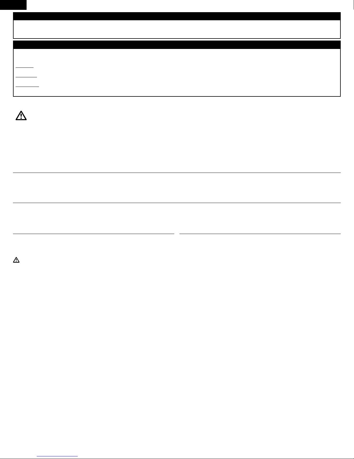
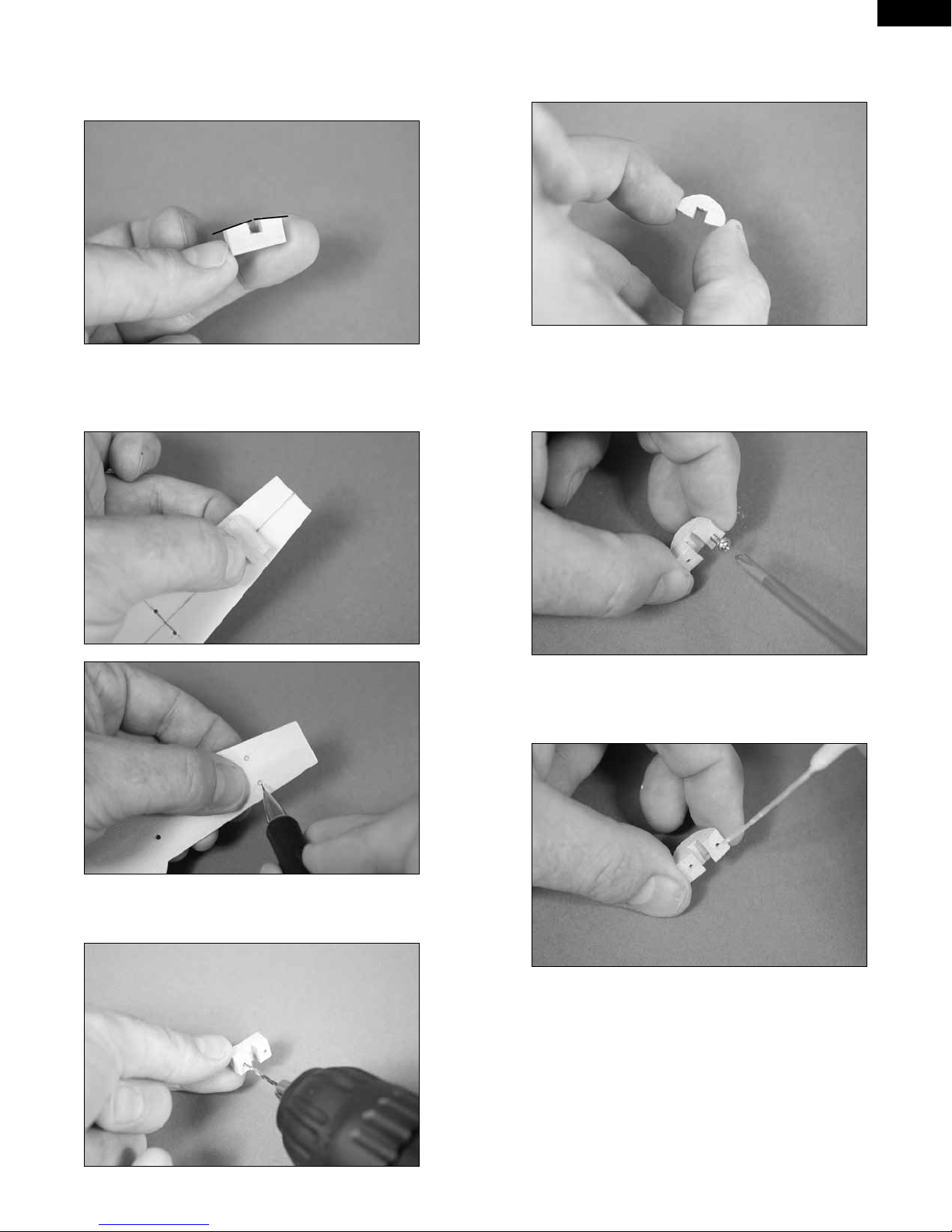
1. Check the fit of the fiberglass control horn in the slot
in the aileron. The hole in the control horn will align with the hinge line,
and the horn will fit flush in the hole. Use a felt-tipped pen to mark the
front and rear edge of the control horn on the aileron.
Adhesives
5-minute epoxy PAAPT38
15-minute epoxy MEUEPX15MIN
CA accelerator PAAPT715
Canopy glue PAAPT56
Medium CA PAAPT02
Thin CA PAAPT08
Threadlock PAAPT42
E-tips
During the course of building your model we suggest you use a soft
base for the building surface. Such things as a foam stand, large piece
of bedding foam or a thick bath towel will work well and help protect the
model from damage during assembly. This is not shown in the instructions to provide the greatest detail in the photos.
When referencing directions (up, down, left, right top and bottom) these
directions are in relationship to the pilot sitting in the cockpit of the
aircraft unless noted otherwise.
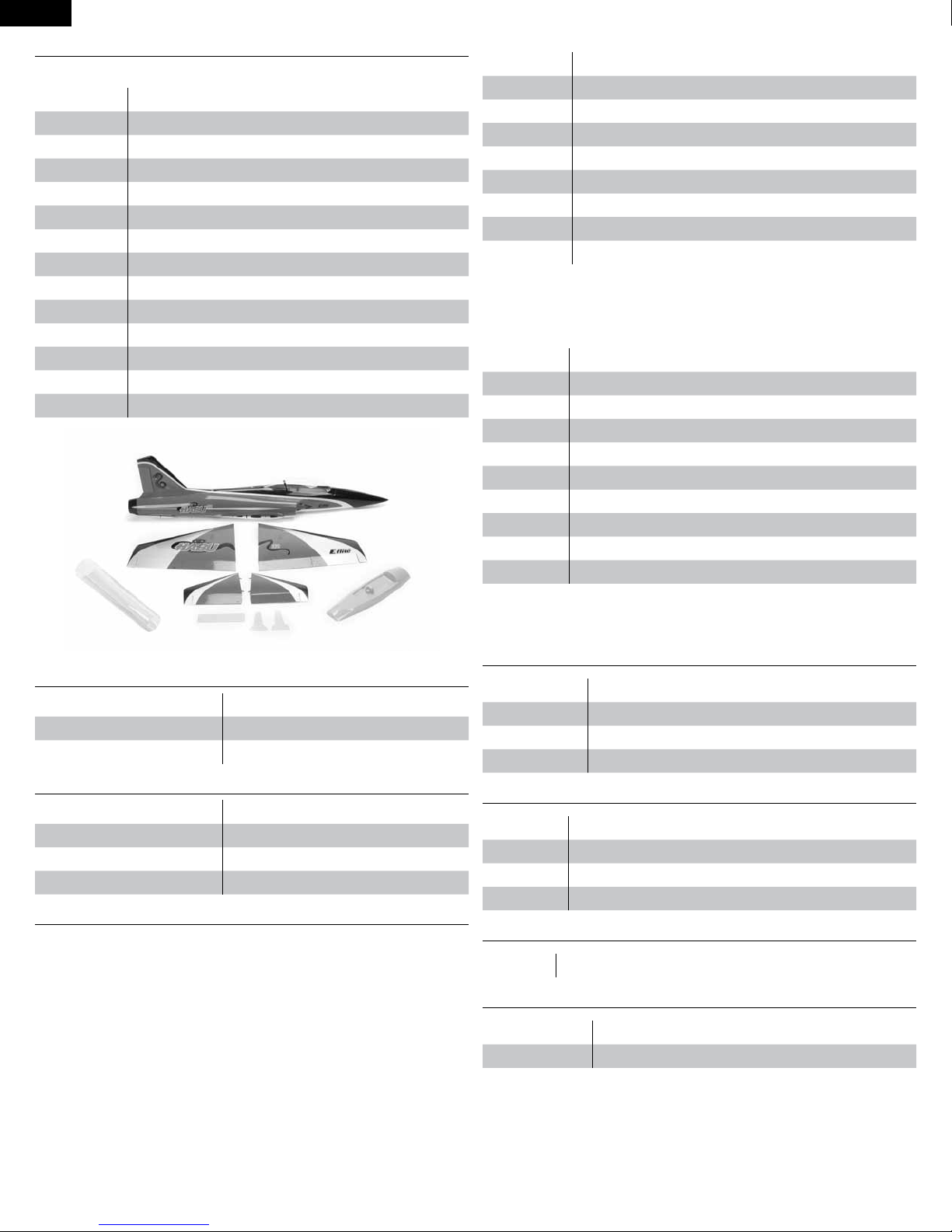
2. Apply low-tack tape around the opening for the flap
and aileron control horn. Position the tape so it is 1/32-inch (1mm) away
from the sides of the hole, as well as from the marks made in the previous
step.
5
Page 6
EN
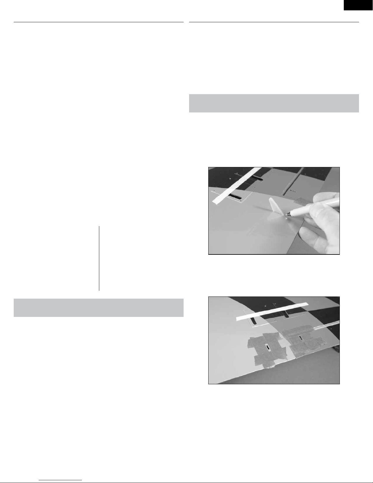
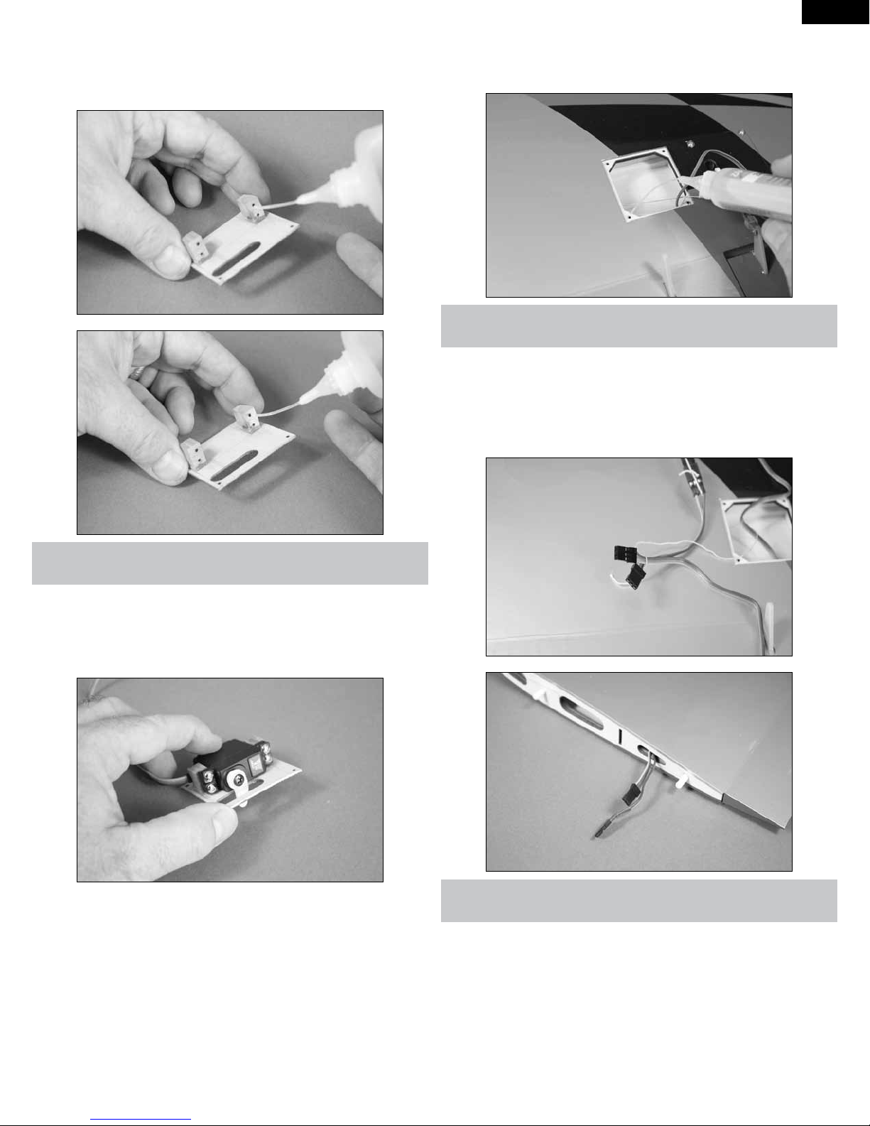
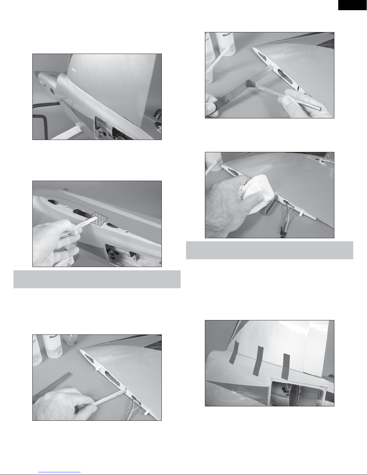
3. Use medium grit sandpaper to lightly sand the control
horns where they fit into the openings in the flap and aileron.
4. Use 5-minute epoxy to glue the control horns into the
holes for the flap and aileron. Use a square to make sure the control horn
is perpendicular to the control surface. Also check again to make sure the
hole in the control horn is directly over the hinge line.
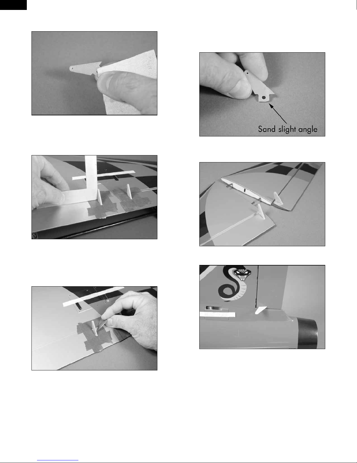
7. Sand a slight angle on the fiberglass control horn for the elevator.
This is so the top of the horn does not distort the covering on the top of
the elevator. Test fit the fiberglass control horn in the slot in the elevator,
making sure the horn does not distort the covering on the top of the
elevator.
8. Repeat steps 1 through 5 to glue the control horns in both elevator
halves.
5. After around 3 minutes, before the epoxy cures,
carefully remove the tape from around the control horns. Pull the tape
away from the horn, being careful not to disturb the position of the control
horn. This will allow the epoxy to flow out slightly, leaving a fillet between
the control horn and control surface.
6. Repeat Steps 1 through 5 to install the remaining aileron and
flap control horn.
9. Repeat steps 1 through 5 to glue the control horn in the rudder.
6
Page 7
AILERON SERVO INSTALLATION
Required Parts
Wing panel (right and left) Transmitter
Receiver Receiver battery
Silicone tubing Metal clevis (4)
2mm nut (4) Servo with hardware (MC35) (2)
Servo extension, 3-inch (76mm) (2) Threaded rod, 2mm x 25mm(2)
Hardwood block,
13mm x 10mm x 7mm (4)
Required Tools and Adhesives
Ruler Phillips screwdriver: #1
Scissors Hobby knife with #11 blade
String Pencil
Thin CA 5-minute epoxy
Mixing cup Mixing stick
Drill Drill bit: 5/64-inch (2mm)
Rotary tool Sanding drum
Medium grit sandpaper
2mm x 8mm self-tapping screw
(8)
EN
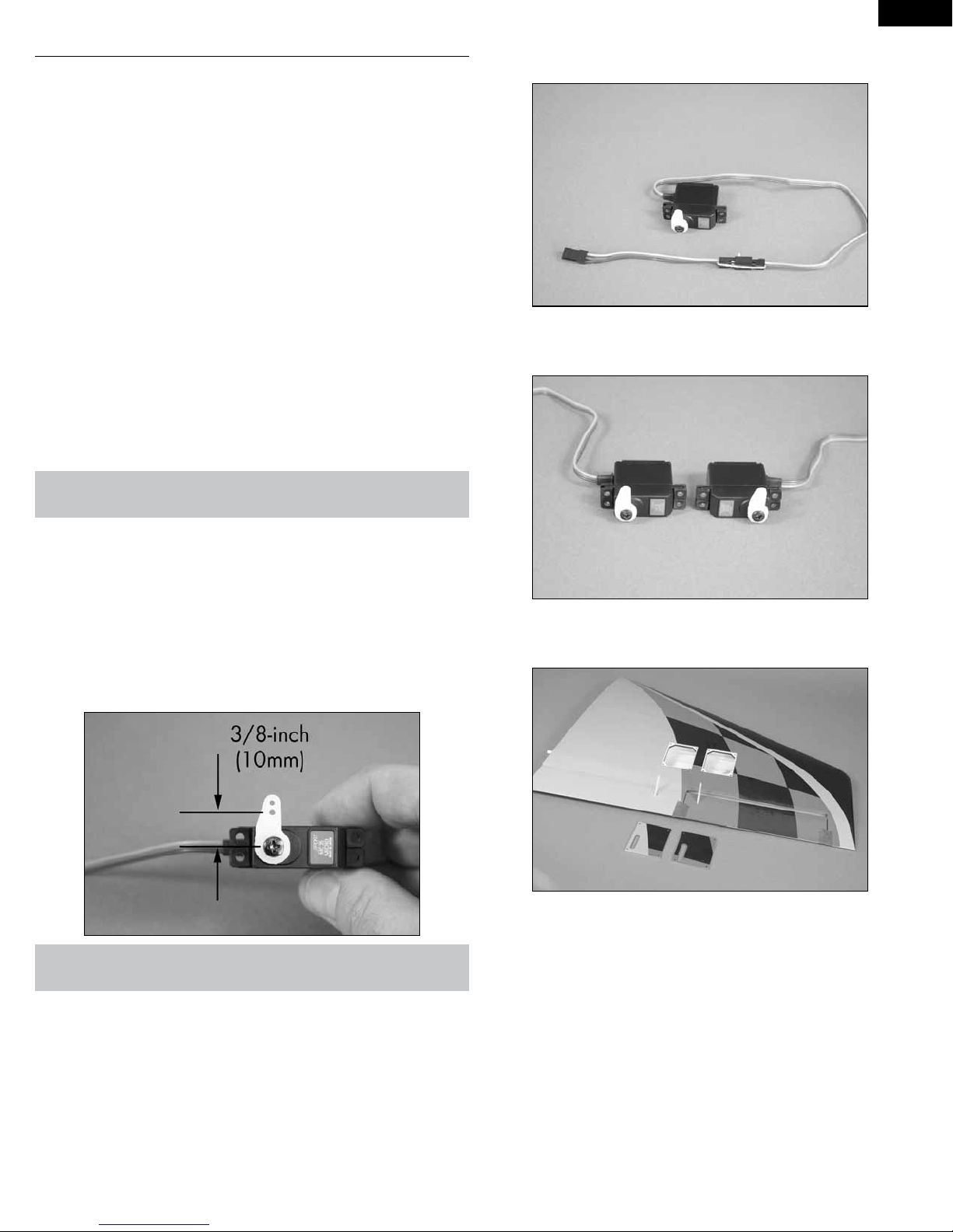
2. Secure a 3-inch (76mm) servo extension to the aileron servo lead
using string or a commercially available connector.
3. Repeat steps 1 and 2 to prepare a second aileron servo. Note the
servos will be mirror images of each other.
E-tips
Before starting the installation of the servos, we recommend centering
the trims and sticks on your transmitter. If using a computer radio, make
sure to reset a model memory and name it for this particular model. We
also recommend binding the transmitter and receiver at this time following the instructions provided with your radio system.
1. Prepare the aileron servo by installing the rubber grommets and
brass eyelets as shown in the radio or servo instructions. Center the
aileron servo using the radio system. Use side cutters to remove any arms
from the horn that may interfere with the operation of the servo.
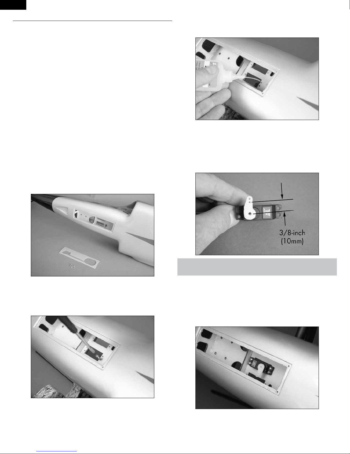
4. Remove the cover from the wing for the flap and aileron servos.
Set the cover aside for the flap servo at this time.
E-tips
The aileron linkage will be connected to the hole in the servo horn 3/8inch (10mm) from the center of the arm as illustrated in the photo above.
7
Page 8
EN
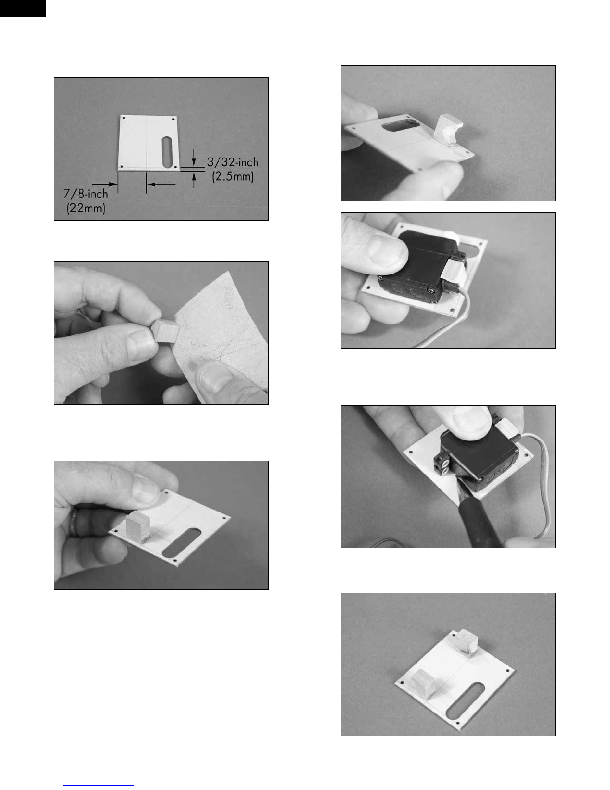
5. Use a pencil to draw two lines on the cover. The first line is along
the bottom of the cover, 3/32-inch (2.5mm) from the edge. The second line
is 7/8-inch (22mm) from the side of the cover as shown. This will center
the servo horn in the slot when using the recommended servos.
6. Sand the 10mm x 7mm end of the block using medium grit
sandpaper. This will be the end glued to the plate in the next step.
8. Use a rotary tool and small sanding drum to make a notch in the
block for the servo lead. Check the fit of the servo to make sure the servo
lead can clear the mounting block.
7. Use 5-minute epoxy to glue the 13mm x 10mm x 7mm hardwood
block to the servo cover. Make sure to glue the 10mm x 7mm end to the
surface of the plate. Allow the epoxy to fully cure before proceeding.
9. Position the aileron servo with the grommets resting on the first
mounting block and the servo parallel to the line on the cover. Use a pencil
to mark the location for the remaining servo mounting block.
10. Use 5-minute epoxy to glue the remaining block to the cover.
Don’t forget to roughen the end of the block as shown in step 6.
8
Page 9

11. Position the servo between the two blocks. Leave a small gap
between the servo and servo cover so vibrations from the airframe are not
transferred directly into the servo. Use a pencil to mark the locations for
the four servo mounting screws on the blocks.
12. Use a drill and 5/64-inch (2mm) drill bit to drill the holes for the
mounting screws. Use care not to enlarge the holes any larger than the
drill bit.
EN
14. Use the screws provided with the servo and a #1 Phillips
screwdriver to attach the servo to the mounting blocks.
15. Apply 2–3 drops of thin CA in each of the aileron servo cover
mounting holes. This will harden the surrounding wood, making the
screws more secure when they are installed.
13. Apply 2–3 drops of thin CA in each hole drilled. Also saturate
the front and rear of the block using thin CA to harden the block. This will
help keep the block from splitting when the servo mounting screws are
installed.
E-tips
Do not use a CA accelerator. Using an accelerator will not allow the CA to
soak into the fibers of the wood, hardening the blocks.
16. Tie the end of the string around the end of the aileron servo lead.
Use the string to pull the aileron servo lead into the flap servo bay.
9
Page 10

EN
17. Use four 2mm x 8mm self-tapping screws and a #1 Phillips
screwdriver to secure the aileron servo cover to the wing.
18. Use a hobby knife with a #11 blade to trim two 1/4-inch (6mm)
pieces from the silicone tubing.
20. Remove the tape holding the flap and aileron in position. Use
the radio system to center the aileron servo. Connect the metal clevis
to the inner hole of aileron servo horn. The remaining clevis connects to
the aileron control horn. Adjust the length of the linkage so the aileron is
centered when the servo is centered. Once the length of the linkage has
been adjusted, slide the tubing over the forks of the clevises to keep them
from accidentally opening in flight. Use needle nose pliers to tighten the
nuts against the metal clevises.
21. Repeat steps 4 through 20 to install the remaining aileron servo
and linkage.
E-tips
Always use threadlock on metal-to-metal fasteners to prevent them from
vibrating loose.
19. Assemble the aileron linkage using the two pieces of tubing
from the previous step, two 2mm nuts, two metal clevises and the 2mm x
25mm threaded rod. The length of the rod will be adjusted in the following
steps.
10
Page 11
FLAP SERVO INSTALLATION
Required Parts
Wing panel (right and left) Transmitter
Receiver Receiver battery
Silicone tubing Metal clevis (4)
2mm nut (4) Servo with hardware (MC35) (2)
Threaded rod, 2mm x 25mm (2) Hardwood block,
13mm x 10mm x 7mm (4)
2mm x 8mm self-tapping screw
(8)
Required Tools and Adhesives
Ruler Phillips screwdriver: #1
Scissors Hobby knife with #11 blade
String Pencil
Thin CA 5-minute epoxy
Mixing cup Mixing stick
Drill Drill bit: 5/64-inch (2mm)
Low-tack tape Rotary tool
Sanding drum
EN
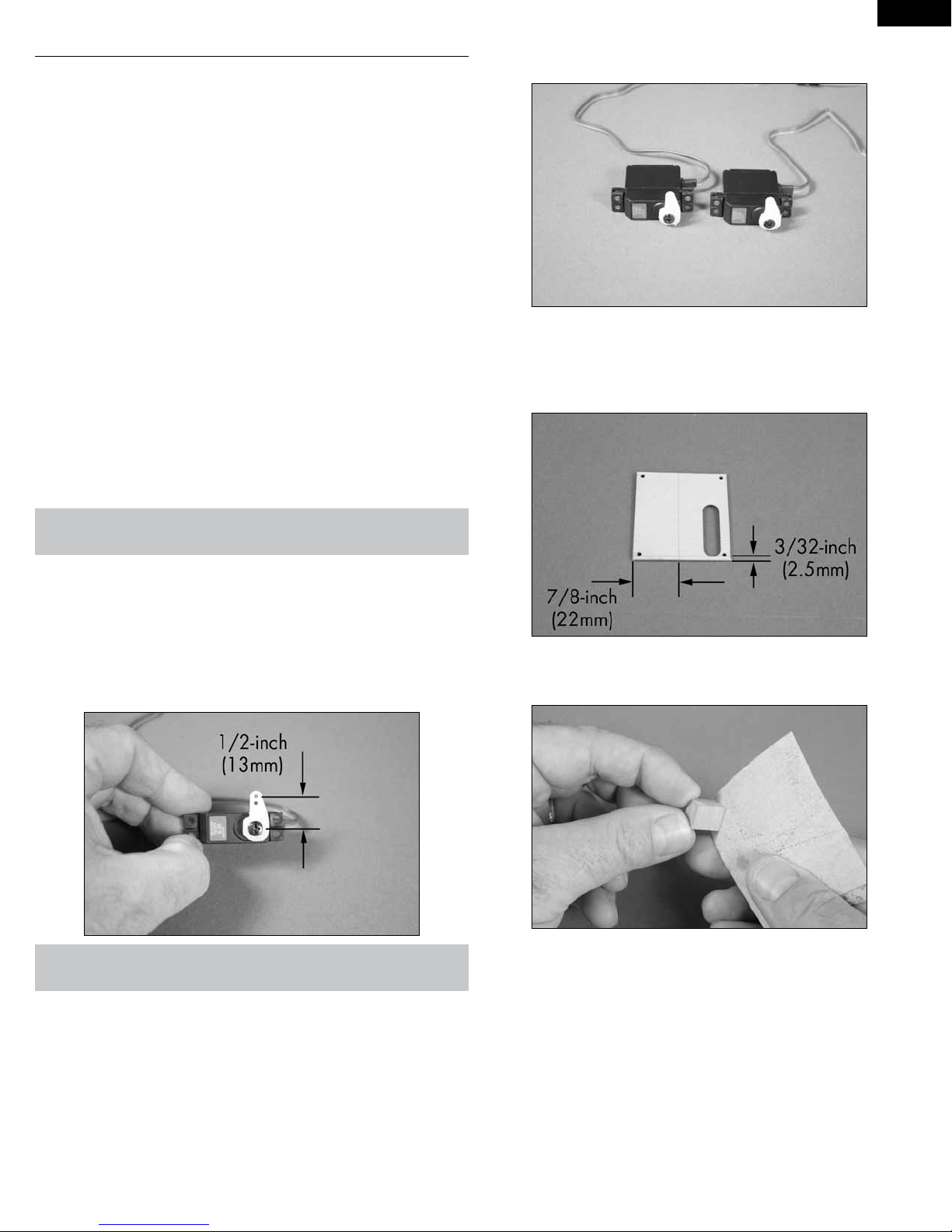
2. Repeat step 1 to prepare a second flap servo. Note the servos will
be identical.
3. Use a pencil to draw two lines on the cover. The first line is along
the bottom of the cover, 3/32-inch (2.5mm) from the edge. The second line
is 7/8-inch (22mm) from the side of the cover as shown. This will center
the servo horn in the slot when using the recommended servos.
E-tips
When centering the flap servo, begin by setting the throws at the transmitter to 0% for both the up and down flap positions. This is done for
both 2- and 3-position flap switches.
1. Prepare the flap servo by installing the rubber grommets and
brass eyelets as shown in the radio or servo instructions. Center the flap
servo using the radio system. Use side cutters to remove any arms from
the horn that may interfere with the operation of the servo.
E-tips
The flap linkage will be connected to the hole in the servo horn 1/2-inch
(13mm) from the center of the arm as illustrated in the photo above.
4. Sand the 10mm x 7mm end of the block using medium grit
sandpaper. This will be the end glued to the plate in the following step.
11
Page 12
EN
5. Use 5-minute epoxy to glue the 13mm x 10mm x 7mm hardwood
block to the servo cover. Make sure to glue the 10mm x 7mm end to the
surface of the plate. Allow the epoxy to fully cure before proceeding.
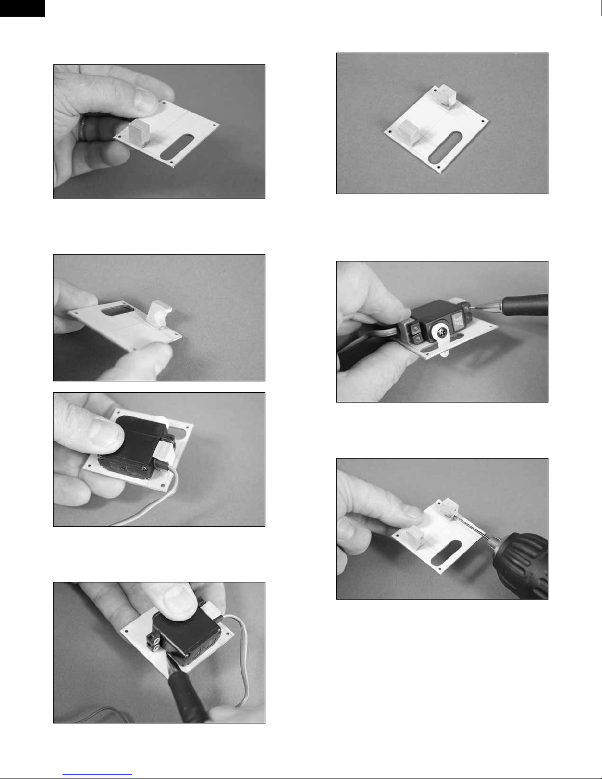
8. Use 5-minute epoxy to glue the remaining block to the cover.
Don’t forget to roughen the end of the block as shown in step 6.
6. Use a rotary tool and small sanding drum to make a notch in the
block for the servo lead. Check the fit of the servo to make sure the servo
lead can clear the mounting block.
9. Position the servo between the two blocks. Leave a small gap
between the servo and servo cover so vibrations from the airframe are
not transferred directly into the servo. Use a pencil to mark the locations
for the four servo mounting screws on the blocks.
10. Use a drill and 5/64-inch (2mm) drill bit to drill the holes for the
mounting screws. Use care not to enlarge the holes any larger than the
drill bit.
7. Position the flap servo with the grommets resting on the first
mounting block and the servo parallel to the line on the cover. Use a pencil
to mark the location for the remaining servo mounting block.
12
Page 13
11. Apply 2–3 drops of thin CA in each hole drilled. Also saturate
the front and rear of the block using thin CA to harden the block. This will
help keep the block from splitting when the servo mounting screws are
installed.
EN
13. Apply 2–3 drops of thin CA in each of the flap servo cover
mounting holes. This will harden the surrounding wood, making the
screws more secure when they are installed.
E-tips
Place a piece of low-tack tape on the flap servo lead so it can be identified easily from the aileron servo lead.
14. Tie the end of the string around the end of the flap and
aileron servo leads. Use the string to pull the leads through the wing
and out at the root rib as shown.
E-tips
Do not use a CA accelerator. Using an accelerator will not allow the CA to
soak into the fibers of the wood, hardening the blocks.
12. Use the screws provided with the servo and a #1 Phillips
screwdriver to attach the servo to the mounting blocks.
E-tips
Use low-tack tape to tape the flap and aileron servo connectors together.
This will make them easier to pull through the wing.
13
Page 14
EN
15. Use four 2mm x 8mm self-tapping screws and a #1 Phillips
screwdriver to secure the flap servo cover to the wing.
16. Use a hobby knife with a #11 blade to trim two 1/4-inch (6mm)
pieces from the silicone tubing.
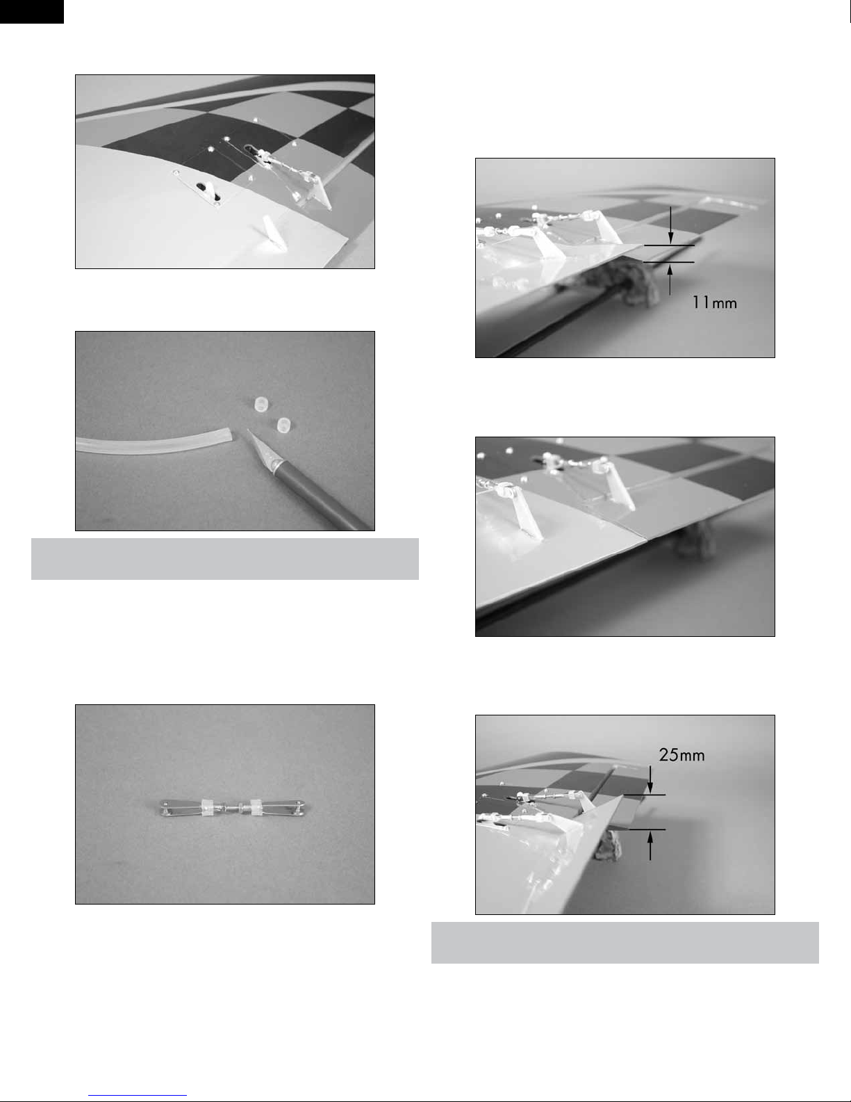
18. Use the radio system to center the flap servo. Connect the metal
clevis to the outer hole of flap servo horn. The remaining clevis connects
to the flap control horn. Adjust the length of the linkage so the flap is set
to the mid/takeoff position of 11mm. Once the length of the linkage has
been adjusted, slide the tubing over the forks of the clevises to keep them
from accidentally opening in flight. Use needle nose pliers to tighten the
nuts against the metal clevises.
19. Set the switch at the transmitter to the UP flap position. Adjust the
flap system values of the transmitter for the up position until the flap is
aligned with the aileron. This will be the UP flap position.
E-tips
Always use threadlock on metal-to-metal fasteners to prevent them from
vibrating loose.
17. Assemble the flap linkage using the two pieces of tubing from
the previous step, two 2mm nuts, two metal clevises and the 2mm x
25mm threaded rod. The length of the rod will be adjusted in the following
steps.
20. Set the switch at the transmitter to the DOWN flap position. Adjust
the ATV at the transmitter for the down position until the flap is 25mm
below the aileron. This will be the DOWN flap position.
E-tips
Because there can be minor differences in control horn and servo positions, do not connect the linkage as described in steps 19 and 20 to the
opposite flap until you have checked the throws. Doing so may cause the
servo to bind in the UP position, which could cause damage to the flap
servo.
14
Page 15
21. Repeat steps 3 through 18 to install the remaining flap servo and
assemble the flap linkage. Connect the flap linkage to the flap control horn
ONLY at this time.
22. Set the flap switch to the UP flap position. Connect the linkage to
the flap servo and adjust its length until the flap is aligned with the aileron.
This will be the UP flap position.
WING SPAR INSTALLATION
Required Parts
Fuselage Carbon wing spar (2)
8-32 x 1/4-inch socket head screw
(4)
Required Tools and Adhesives
Low-tack tape Phillips screwdriver: #1
15-minute epoxy Mixing cup
Paper towels Mixing stick
Epoxy brush Rubbing alcohol
Ruler Medium grit sandpaper
Petroleum jelly Felt-tipped pen
Ball driver: 9/64-inch
1. Use a #1 Phillips screwdriver to remove the four 2mm x 8mm
screws that hold the fan cover to the fuselage. Set the screws and cover
aside in a safe location.
Wing panel assembly (right and
left)
EN
E-tips
You may have to fine-tune both flap linkages up or down so they align
at all three positions: up, middle, and down. It is very important to use
servo arms positioned at the same angle on the splines of the servo so
the travel will match in all positions.
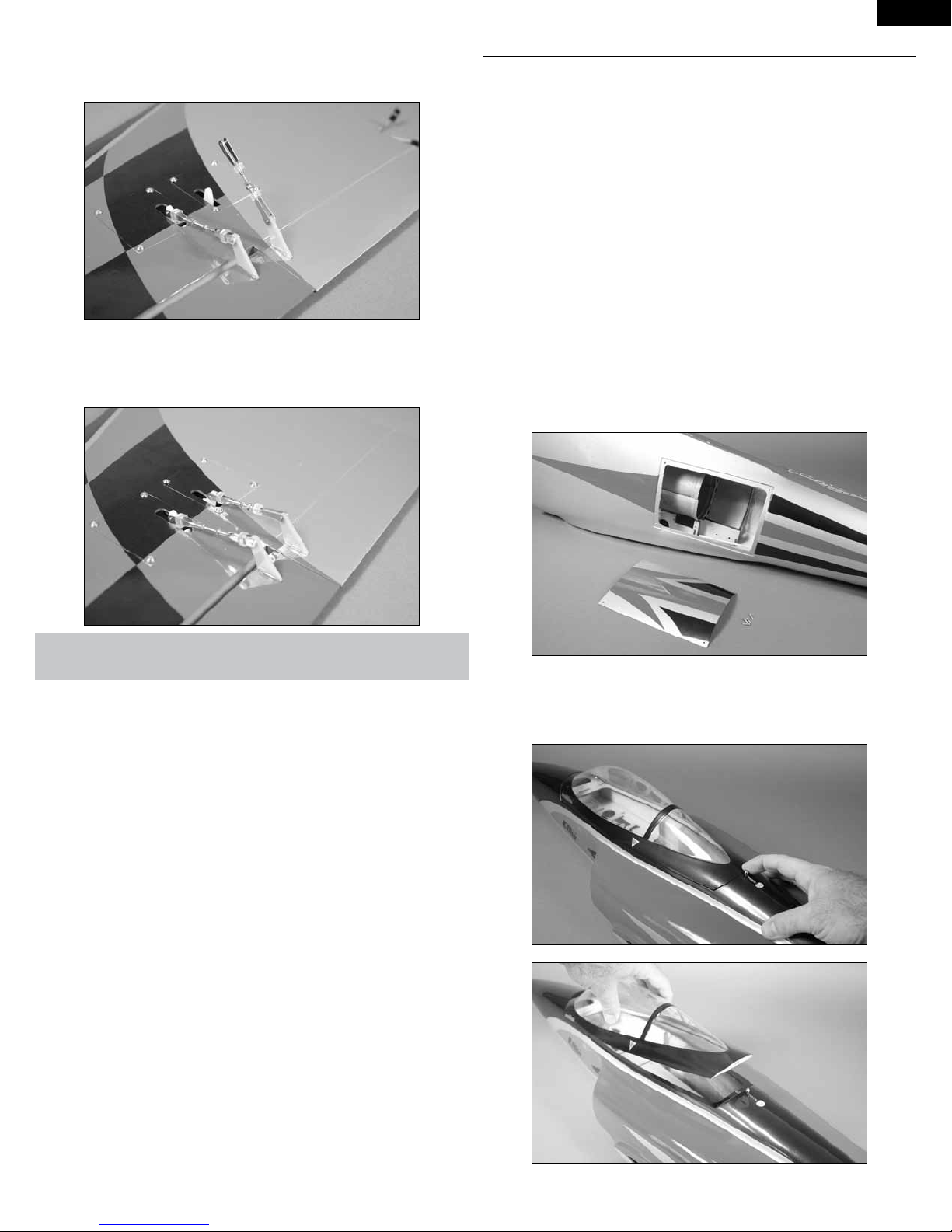
2. Slide the canopy hatch pin rearward and lift the canopy from the
fuselage. The canopy is held in place with two pins at the front. Set the
canopy aside so it doesn’t get damaged.
15
Page 16
EN
3. Use a 9/64-inch ball driver to start the four 8-32 x 1/4-inch socket
head bolts in the aluminum wing sockets inside the fuselage. Only thread
the screws in a few turns at this time. Use care not to cross-thread the
screws and damage the threads in the aluminum sockets.
6. Remove the spar from the spar pocket. Use medium grit
sandpaper to lightly sand the spar where it fits into the wing. Sand both
the front and back of the spar.
4. Locate the carbon wing spar. Use a straight edge or rest the joiner
on a flat surface. The top of the joiner is flat, while the bottom will have a
slight angle as shown in the drawing. This is necessary to conform to the
dihedral built into the model.
Top
*Not to scale
5. Slide the carbon wing spar in the spar pocket of the wing, narrow
end first. Make sure the top of the spar is to the top of the wing. The spar
will slide in easily, so don’t force it in any further than it will slide. Use a
felt-tipped pen to mark the spar at the wing root.
7. Slide the spar into the spar pocket in the fuselage. It will easily slide
into the pocket up to the line made in step 5. If not, the screws installed in
step 3 may be in the way and will need to be loosened.
8. Move the string used to pull the retract servo lead through the
wing into the wing so it doesn’t interfere with the fit of the wing to the
fuselage.
16
Page 17
9. Check the fit of the wing on the fuselage. It must rest tightly
against the fuselage. If the spar fits into the wing and fuselage spar
pockets without any problems, the fit should be perfect. Make sure to
guide the leads for the aileron and flap into the fuselage so they don’t
interfere with the fit.
10. Remove the wing and spar from the fuselage. Apply a thin coat
of petroleum jelly to the fuselage around the wing socket. This will keep
you from accidentally gluing the wing to the fuselage during the following
procedure.
EN
12. Use an epoxy brush to apply epoxy to the front, back, top and
bottom of the spar where it fits into the wing.
13. Slide the spar into the spar pocket of the wing, making sure it is
oriented correctly. Use a paper towel and rubbing alcohol to remove any
excess epoxy from the wing and spar.
E-tips
Before mixing any epoxy, make sure to read through and understand the
following steps. It is important to perform these steps before the epoxy
fully cures.
11. Mix 1/2 ounce (15mL) of 15-minute epoxy. Apply the epoxy to
the spar pocket of the wing using a mixing stick.
E-tips
Epoxy will ooze out from the spar pocket of the wing. If epoxy does not
ooze out, not enough epoxy was used to glue the spar into the wing.
14. Before the epoxy cures, slide the wing into position against the
fuselage. Keep the wing tight against the fuselage until the epoxy fully
cures. You can use a 9/64-inch ball driver to lightly tighten the screws to
secure the wing joiner in the fuselage, and low-tack tape to hold the wing
in position until the epoxy has cured.
15. Once the epoxy has cured, remove the wing panel from the
fuselage. Repeat steps 4 through 14 to install the remaining wing panel to
the fuselage.
16. Once the epoxy has fully cured and both wing panels have spars,
remove any petroleum jelly residue from the fuselage and wing using
rubbing alcohol and a paper towel.
17
Page 18
EN
MAIN LANDING GEAR INSTALLATION -
FIXED GEAR
Required Parts
Wing panel assembly (right and
left)
Aluminum wheel spacer, 3.5mm
(2)
Wheel axle adapter set (2) Main landing gear strut (right and
Main fixed landing gear unit (2) 3mm x 14mm countersunk self-
Required Tools and Adhesives
Drill Drill bit: 5/64-inch (2mm)
Threadlock Hex wrench: 1.5mm
Thin CA Phillips screwdriver: #1
Trim seal tool Hobby knife with #11 blade
Triangle Flat file
NOTE: If you are installing retracts, skip to the next section of this manual,
Main Landing Gear Installation - Retractable Gear.
Aluminum wheel collar with
setscrew, 3.5mm (2)
3
Wheel, 1
/4-inch (44.5mm) (2)
left)
tapping screw (8)
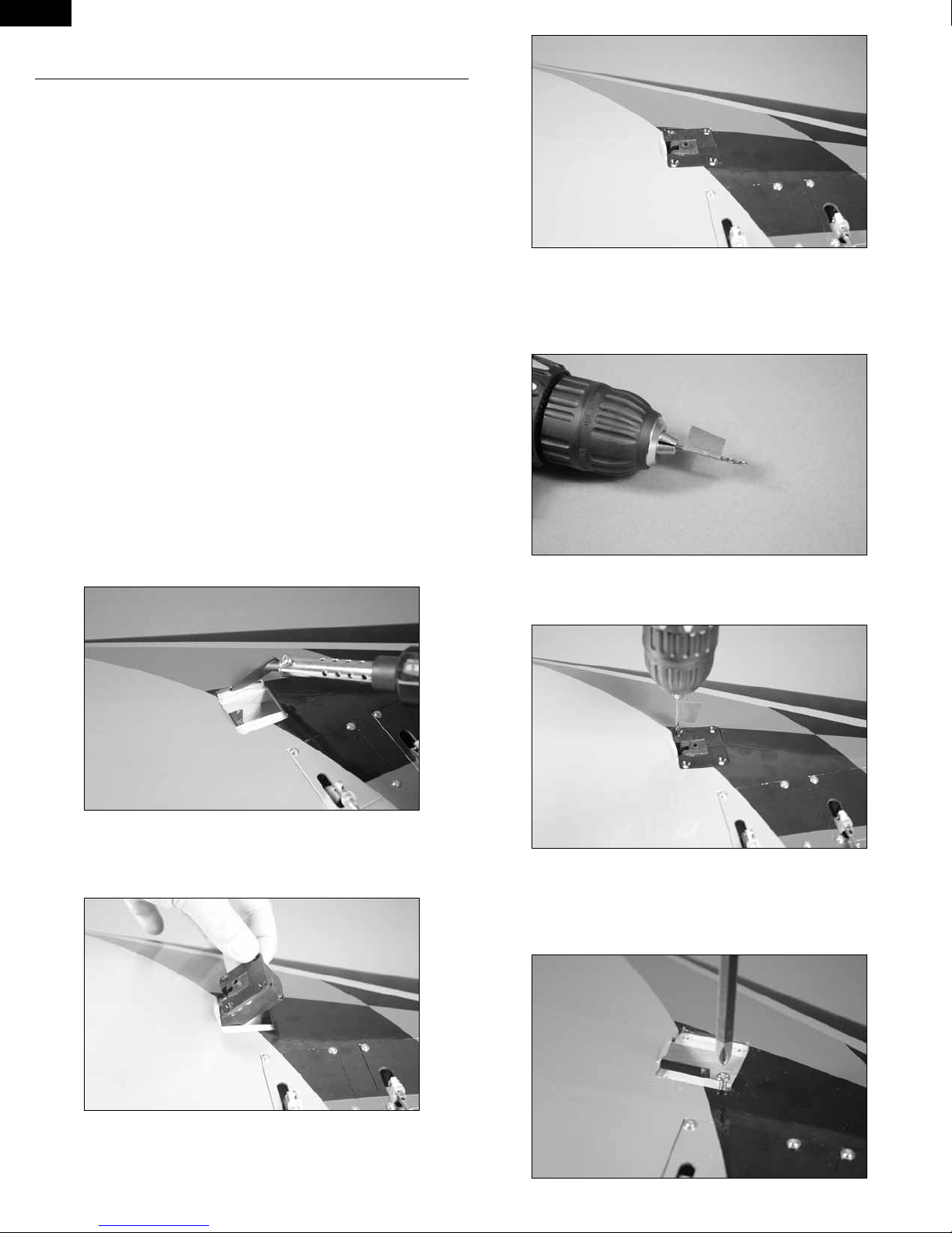
3. Prepare a 5/64-inch (2mm) drill bit by wrapping a piece of low-tack
tape around the drill bit 5/8-inch (16mm) from the end of the bit. This will
act as a marker so you don’t accidentally drill through the top of the wing.
Place the drill bit in a drill.
1. Use a hobby knife with a new #11 blade to remove the covering
to access the landing gear mounts. Leave 1/32-inch (1mm) of covering
around the inside edges. Use a trim seal tool to iron down the covering
around the edges to finish the opening.
2. Place a main landing gear block in the wing. It may distort the
covering slightly during its installation. Make sure it is resting flat on the
landing gear rails.
4. Use the drill and drill bit prepared in the previous step to drill the
four holes for the landing gear block mounting screws.
5. Remove the landing gear block from the wing. Use a #1 Phillips
screwdriver to thread a 3mm x 14mm countersunk self-tapping screw in
each hole to cut threads into the landing gear rails. Remove the screws
after threading the holes.
18
Page 19
6. Place 2–3 drops of thin CA in each of the holes. This will harden
the threads made by the screws making them more secure when the
landing gear block is installed.
EN
9. With the flap lowered, rest a square against the flap hinge line.
Look down on the axle and check that it is perpendicular to the square
as shown. If not, it may be necessary to lightly file the flat areas on the
landing gear wire to correct for any misalignment.
E-tips
Always use threadlock on metal-to-metal fasteners to prevent them from
vibrating loose.
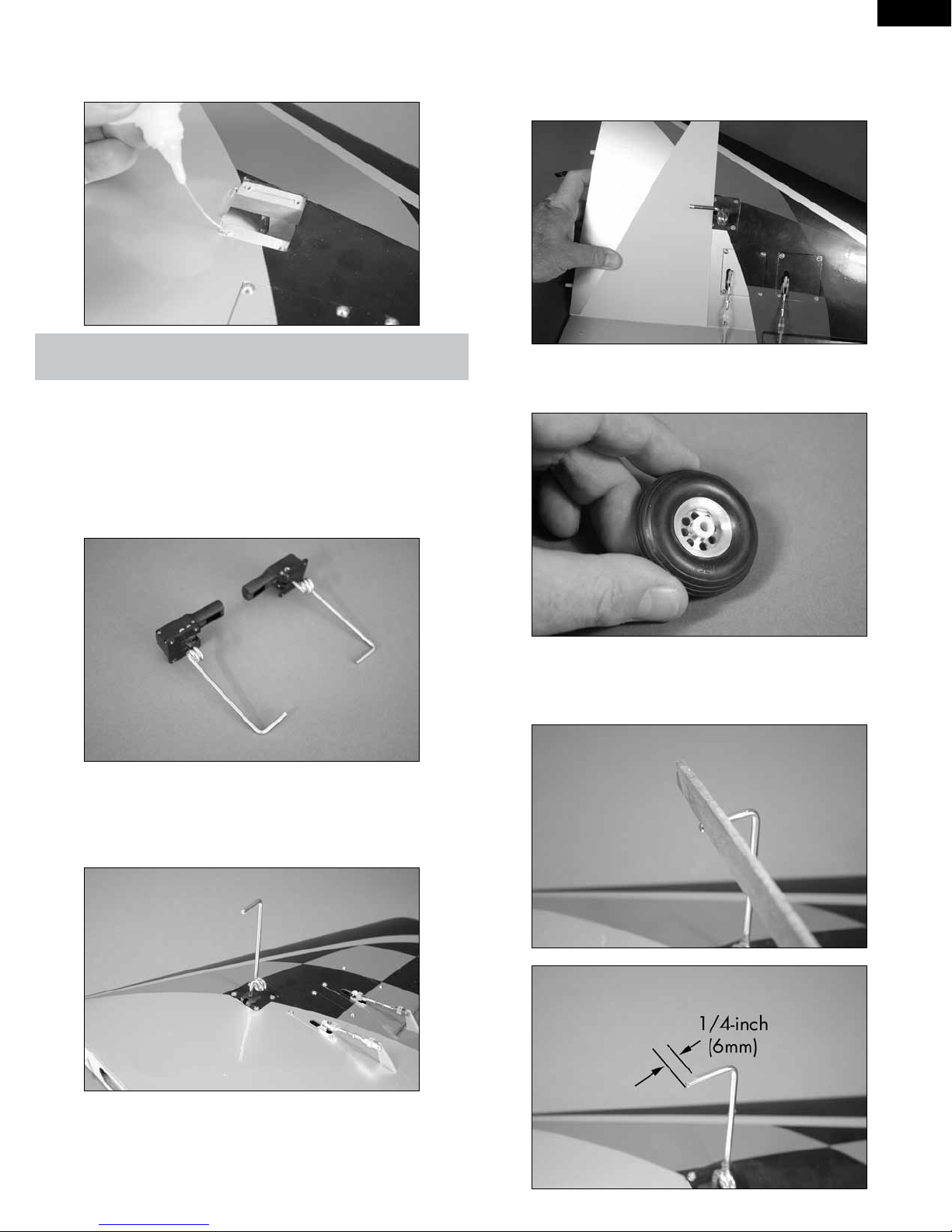
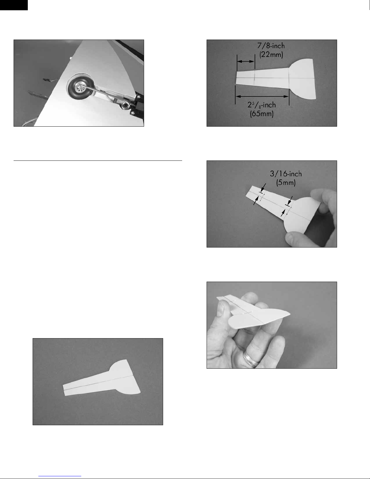
7. Slide a main gear strut into the main landing gear block. Use the
setscrews and a 1.5mm hex wrench to secure the main gear wire in the
block. The setscrews will tighten down on each side of the flat at the top
of the strut to prevent the strut from rotating in the block. Assemble the
right and left main gear assemblies at this time.
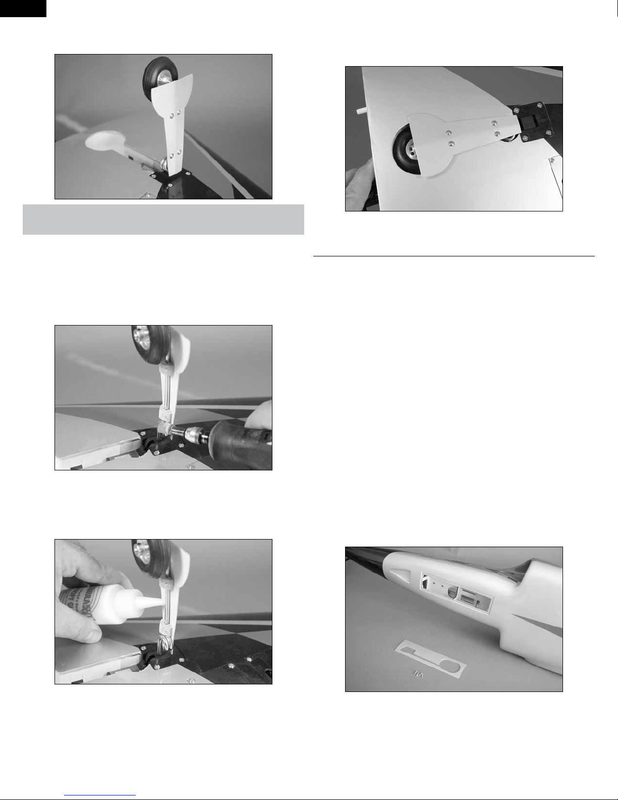
8. Place the correct main gear assembly in position. The axle will face
to the root of the wing, and the spring will face to the trailing edge of the
wing. Use four 3mm x 14mm countersunk self-tapping screws and a #1
Phillips screwdriver to tighten the screws.
10. Select the correct adapter that fits to the landing gear strut.
Insert two adapters in either side of the hub of the wheel.
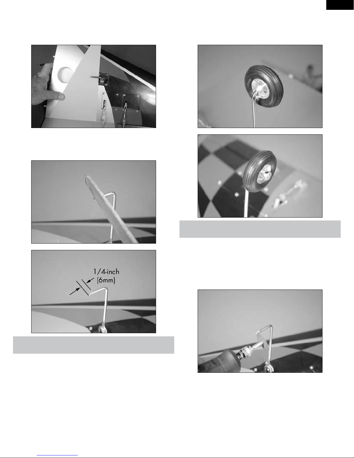
11. Use a flat file to make a 1/4-inch (6mm) wide flat area on the
gear near the end of the axle strut for the setscrew to rest. This will keep
the wheel collar from vibrating loose in flight.
19
Page 20
EN
E-tips
The end of the axles may have a slight bur on them from the factory. If
the wheel is hard to install use a file to remove this bur.
Always use threadlock on metal-to-metal fasteners to prevent them from
vibrating loose.
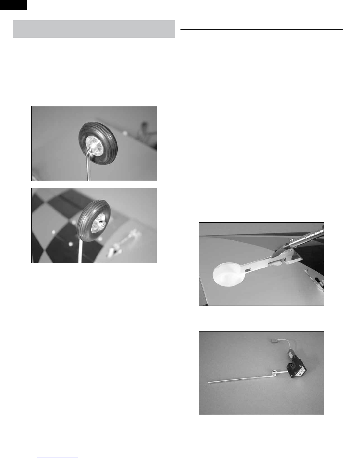
12. Slide a 3.5mm aluminum wheel spacer on the axle, then the
wheel with adapters. A 3.5mm wheel collar is used to secure the wheel
in position by tightening the setscrews onto the axle using a 1.5mm hex
wrench.
MAIN LANDING GEAR INSTALLATION -
RETRACTABLE GEAR
Required Parts
Transmitter Receiver
Receiver battery Wing panel assembly (right and
left)
Servo extension, 3-inch (76mm) (2) Aluminum wheel collar with
setscrew, 3.5mm (2)
3
Aluminum wheel spacer, 3.5mm
(2)
Wheel axle adapter set (2) Main landing gear strut (right and
Main landing gear retract (2) 3mm x 14mm countersunk self-
Required Tools and Adhesives
Drill Drill bit: 5/64-inch (2mm)
Threadlock Hex wrench: 1.5mm
Thin CA Phillips screwdriver: #1
String Scissors
Trim seal tool Hobby knife with #11 blade
Wheel, 1
left)
tapping screw (8)
/4-inch (44.5mm) (2)
13. Repeat steps 1 through 12 to install the remaining main landing
gear and wheel.
1. Use a hobby knife with a new #11 blade to remove the covering for
the retract mechanism and landing gear assembly. Leave 1/32-inch (1mm)
of covering around the inside edges. Use a trim seal tool to iron down the
covering around the edges to finish the opening.
2. Use a 1.5mm hex wrench to remove the strut from the retract
mechanism.
20
Page 21
3. Place the retract mechanism in the wing. Make sure it is resting
flat on the landing gear rails.
EN
6. Remove the retract mechanism from the wing. Use a #1 Phillips
screwdriver to thread a 3mm x 14mm countersunk self-tapping screw in
each hole to cut threads into the landing gear rails. Remove the screws
after threading the holes.
7. Place 2–3 drops of thin CA in each of the holes. This will harden
the threads made by the screws making them more secure when the
landing gear block is installed.
4. Prepare a 5/64-inch (2mm) drill bit by wrapping a piece of low-tack
tape around the drill bit 5/8-inch (16mm) from the end of the bit. This will
act as a marker so you don’t accidentally drill through the top of the wing.
Place the drill bit in a drill.
5. Use the drill and drill bit prepared in the previous step to drill the
four holes for the landing gear block mounting screws.
E-tips
We have designed the main gear struts to work with both the fixed gear
and the suggested retracts. These struts are designed for the weight and
speeds of the Habu. Use the struts supplied with the kit for the retract
assemblies.
E-tips
Always use threadlock on metal-to-metal fasteners to prevent them from
vibrating loose.
21
Page 22
EN
8. Slide a main gear strut into the retract mechanism. Use the
setscrews and a 1.5mm hex wrench to secure the main gear wire in the
mechanism. The setscrews will tighten down on the flats at the top of the
strut to prevent the strut from rotating in the block. Assemble the right and
left main gear retract assemblies at this time.
NOTE: The first shipment of EFL 15–25 size retracts were shipped with only
one setscrew holding in the main strut. This is fine for the lower weight
limits of the retracts, but for the higher end of the weight limits, we suggest
using a setscrew in each side of the strut. Future shipments will have a
setscrew in each side of the unit. If your units only have a setscrew in one
side of the unit, remove another setscrew for each of the fixed gear units
supplied with the kit.
11. Use the string to pull the lead through the wing and out at
the root rib as shown. Remove the string once the lead has been pulled
through.
12. Place the correct retract assembly in position. The axle will face to
the root of the wing, and the spring will face to the trailing edge of the wing.
Use four 3mm x 14mm countersunk self-tapping screws and a #1 Phillips
screwdriver to tighten the screws.
9. Secure a 3-inch (76mm) servo extension to the lead on the retract
mechanism using string or a commercially available connector.
10. Tie the end of the string around the end of the extension. Use
care not to pull the string from the wing.
14. Select the correct adapter that fits to the landing gear strut.
Insert two adapters in either side of the hub of the wheel.
22
Page 23
15. With the flap lowered, rest a square against the flap hinge line.
Look down on the axle and check that it is perpendicular to the square
as shown. If not, it may be necessary to lightly file the flat areas on the
landing gear wire to correct for any misalignment.
16. Use a flat file to make a 1/4-inch (6mm) wide flat area on the
gear near the end of the axle strut for the setscrew to rest. This will keep
the wheel collar from vibrating loose in flight.
EN
17. Slide a 3.5mm aluminum wheel spacer on the axle, then the
wheel with adapters. A 3.5mm wheel collar is used to secure the wheel
in position by tightening the setscrews onto the axle using a 1.5mm hex
wrench.
E-tips
Always use threadlock on metal-to-metal fasteners to prevent them from
vibrating loose.
E-tips
The end of the axles may have a slight bur on them from the factory. If
the wheel is hard to install use a file to remove this bur.
18. Check to make sure the axle is flush with the edge of the outer
wheel collar. If not, use a rotary tool and cutoff wheel to trim the axle
flush with the wheel collar. Make sure to remove the wheel so the heat
generated from the cutting does not melt the bushings in the wheel.
23
Page 24
EN
19. Check the operation of the retract using the radio system. The
wheel will retract into the center of the wheel well. If not, slightly bend
the strut so it does.
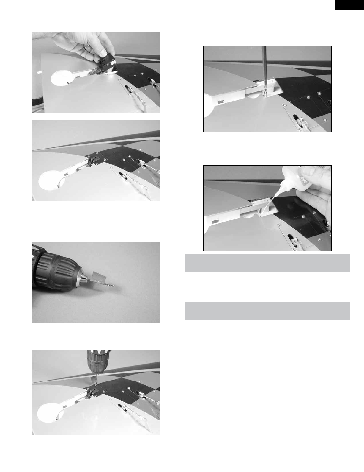
2. Draw two lines on the door that are 7/8-inch (22mm) and 25/8-
inch (65mm) from the top edge of the landing gear door as the center
lines for the mounting blocks.
20. Repeat steps 1 through 19 to install the remaining main landing
gear and wheel.
OPTIONAL MAIN LANDING GEAR DOORS
Required Parts
Wing assembly (right and left) Transmitter
Receiver Receiver battery
Landing gear door (2) 2mm x 8mm self-tapping screw
(8)
Landing gear door block (4)
Required Tools and Adhesives
Rotary tool Sanding drum
Sanding block Medium grit sandpaper
Ruler Pencil
Pin vise Drill
Canopy glue Drill bit: 1/16-inch (1.5mm)
Thin CA Side cutter
Phillips screwdriver: #0
NOTE: The installation of the landing gear doors is optional and they can
be installed at any time during the life of your model.
3. Use a pin vise and 1/16-inch (1.5mm) drill bit to drill four holes in
the landing gear door that are 3/16-inch (5mm) from the centerline along
the lines drawn in the previous step.
4. Use a straight edge or ruler to lightly bend the landing gear door
so it will rest tightly against the wing when the gear are retracted. Work
slowly to avoid cracking the paint on the outside of the landing gear door.
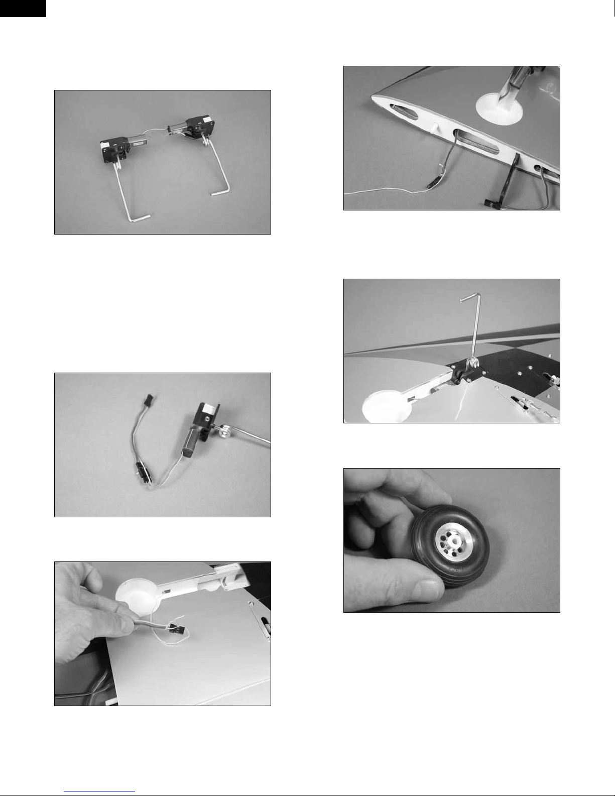
1. Use a pencil to draw a centerline on the unpainted side of the
landing gear door.
24
Page 25
5. Locate the landing gear door blocks. Use a sanding block and
medium grit sandpaper to sand an angle on the notched side so the block
will rest flat against the angle of the landing gear door. Prepare both
blocks at this time.
6. Rest the landing gear door block on the gear door, centering it on
the lines previously drawn. Use a pencil to transfer the mounting holes
from the landing gear door onto the block.
EN
8. Use a sanding block and medium grit sandpaper to round
the back of the landing gear door block. This will allow the gear to
retract into the wing and help center the gear while it is retracting.
9. Use a #0 Phillips screwdriver to install a 2mm
x 8mm self-tapping screw in each of the mounting holes in the landing
gear door block. Remove the screws after cutting the threads in the
blocks.
7. Use a drill and 1/16-inch (1.5mm) drill bit to drill
the two mounting holes in the landing gear door block.
10. Place 2–3 drops of thin CA in each of the
mounting holes. This will harden the threads made by the screws making
them more secure when the landing gear door is installed.
11. Repeat steps 7 through 10 to prepare the second landing gear
door mounting block.
25
Page 26
EN
12. Attach the landing gear door to the strut using four 2mm x 8mm
self-tapping screws and a #0 Phillips screwdriver.
15. Retract the landing gear using the radio system. This will set the
correct angle for the landing gear door against the wing. Allow the glue to
cure overnight before moving the gear back to the down position.
E-tips
Work slowly when using a sanding drum on the screws. The screws will
heat up while sanding, which could melt the landing gear door.
13. Use side cutters and a rotary tool with a sanding drum to smooth
the ends of the screws against the inside of the blocks. If this is not done,
the screws could catch on the edges of the retract opening and cause the
gear to not retract correctly.
14. Slide the landing gear door so the top block is resting against the
coil of the landing gear strut. Apply a thin bead of canopy glue along the
front and back of the strut against the landing gear door. Rotate the door a
few times to work the glue behind the strut.
16.Repeat steps 1 through 15 to install the second landing gear door.
NOSE GEAR INSTALLATION - FIXED GEAR
Required Parts
Fuselage assembly Fixed nose gear assembly
Transmitter Receiver
Receiver battery Silicone tubing
Metal clevis (2) 2mm nut (2)
1
Threaded rod, 2
3mm x 8mm socket head screw
(4)
Aluminum wheel spacer, 3.5mm Wheel, 1
Wheel axle adapter set
Required Tools and Adhesives
Pliers Phillips screwdriver: #1
Side cutter Hobby knife with #11 blade
Clear tape Threadlock
Hex wrench: 1.5mm, 2.5mm
1. Use a #1 Phillips screwdriver to remove the four 2mm x 8mm selftapping screws that secure the nose gear cover to the fuselage. Set the
cover and screws aside until later in the section of the manual.
/4-inch (57mm) Servo with hardware (MC35)
Aluminum wheel collar with
setscrew, 3.5mm
3
/4-inch (44.5mm)
26
Page 27
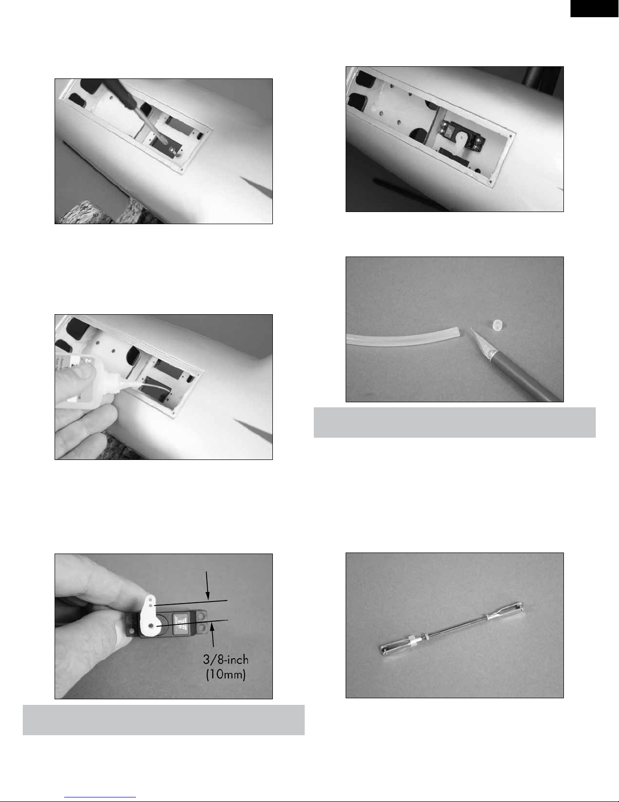
2. Use a #1 Phillips screwdriver to thread a servo mounting screw into
the mounting holes for the steering servo. Remove the screw after cutting
the threads in the plywood. The opening for the steering servo is the
center opening in the forward servo tray.
NOTE: The 2 extra servo holes on each side of the nose gear servo hole
are not used and are just there if needed.
3. Place 2–3 drops of thin CA in each of the holes. This will harden the
threads made by the screws making them more secure when the steering
servo is installed.
EN
5. Install the steering servo in the fuselage using the hardware
provided with the servo and a #1 Phillips screwdriver. The servo output
faces the rear of the fuselage.
6. Use a hobby knife with a #11 blade to trim a 1/4-inch (6mm) piece
from the silicone tubing.
4. Prepare the steering servo by installing the rubber grommets and
brass eyelets as shown in the radio or servo instructions. Center the
steering servo using the radio system. Use side cutters to remove any
arms from the horn that may interfere with the operation of the servo.
Do not secure the horn to the servo, as it will need to be removed when
adjusting the steering linkage.
E-tips
Always use threadlock on metal-to-metal fasteners to prevent them from
vibrating loose.
7. Slide the piece of silicone tubing on one of the metal clevises.
Assemble the steering linkage by threading a 2mm nut and metal clevis
on either end of the 2
clevis without the tubing so the threads are barely visible between the
forks of the clevis, then use pliers to tighten the nut against the clevis to
keep the clevis from moving.
1
/4-inch (57mm) threaded rod as shown. Thread the
E-tips
The steering linkage will be connected to the hole in the servo that is
3/8-inch (10mm) from the center of the arm as illustrated in the photo
above.
27
Page 28
EN
8. Connect the clevis without the tubing to the steering arm of the nose
gear assembly.
E-tips
Cut a 1/2-inch (13mm) piece of silicone tubing and slide it on a 2.5mm
hex wrench. The 3mm screw can then be placed in the tubing and
against the hex wrench so it can be easily installed to secure the landing
gear.
10. Remove the horn from the servo and attach the clevis to the horn.
Place the horn on the servo and check that the steering is centered when
the steering servo is centered. Once the linkage is set, tighten the 2mm
nut against the clevis using pliers so the clevis doesn’t vibrate loose. Slide
the silicone over the forks of the clevis and install the screw to secure the
servo horn to the servo using a #1 Phillips screwdriver.
11. Attach the nose gear cover to the fuselage using a #1 Phillips
screwdriver and the four 2mm x 8mm self-tapping screws removed in
step 1.
E-tips
Always use threadlock on metal-to-metal fasteners to prevent them from
vibrating loose.
9. Secure the nose gear assembly in the fuselage using four 3mm x
8mm socket head screws.
E-tips
Add clear tape to both sides of the nose gear door to help secure it to the
fuselage.
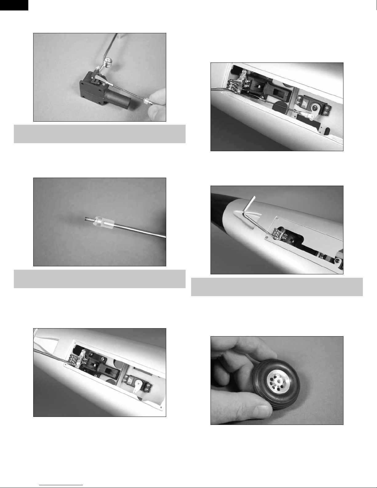
12. Select the correct adapter that fits to the landing gear strut. Insert
two adapters in either side of the hub of the wheel.
28
Page 29

13. Use a flat file to make a 1/4-inch (6mm) wide flat area on the gear
near the end of the axle strut for the setscrew to rest. This will keep the
wheel collar from vibrating loose in flight.
EN
14. Slide a 3.5mm aluminum wheel spacer on the axle, then the
wheel with adapters. A 3.5mm wheel collar is used to secure the wheel
in position by tightening the setscrews onto the axle using a 1.5mm hex
wrench.
E-tips
Always use threadlock on metal-to-metal fasteners to prevent them from
vibrating loose.
E-tips
The end of the axles may have a slight bur on them from the factory. If
the wheel is hard to install use a file to remove this bur.
29
Page 30
EN
NOSE GEAR INSTALLATION - RETRACTS
Required Parts
Fuselage assembly Nose gear retract assembly
Transmitter Receiver
Receiver battery Silicone tubing
Metal clevis (2) 2mm nut (2)
1
Threaded rod, 2
3mm x 8mm socket head screw
(4)
Aluminum wheel spacer, 3.5mm Wheel, 1
Wheel axle adapter set
Required Tools and Adhesives
Pliers Phillips screwdriver: #1
Side cutter Hobby knife with #11 blade
Rotary tool Sanding drum
Threadlock Clear tape
Hex wrench: 1.5mm, 2.5mm
1. Use a #1 Phillips screwdriver to remove the four 2mm x 8mm selftapping screws that secure the nose gear cover to the fuselage. Set the
cover and screws aside until later in the section of the manual.
/4-inch (57mm) Servo with hardware (MC35)
Aluminum wheel collar with
setscrew, 3.5mm
3
/4-inch (44.5mm)
3. Place 2–3 drops of thin CA in each of the holes. This will harden the
threads made by the screws making them more secure when the steering
servo is installed.
4. Prepare the steering servo by installing the rubber grommets and
brass eyelets as shown in the radio or servo instructions. Center the
steering servo using the radio system. Use side cutters to remove any
arms from the horn that may interfere with the operation of the servo.
Do not secure the horn to the servo, as it will need to be removed when
adjusting the steering linkage.
2. Use a #1 Phillips screwdriver to thread a servo mounting screw into
the mounting holes for the steering servo. Remove the screw after cutting
the threads in the plywood. The opening for the steering servo is the
center opening in the forward servo tray.
NOTE: The 2 extra servo holes on each side of the nose gear servo hole
are not used and are just there if needed.
E-tips
The steering linkage will be connected to the hole in the servo that is
3/8-inch (10mm) from the center of the arm as illustrated in the photo
above.
5. Install the steering servo in the fuselage using the hardware
provided with the servo and a #1 Phillips screwdriver. The servo output
faces the rear of the fuselage.
30
Page 31

6. Use a hobby knife with a #11 blade to trim a 1/4-inch (6mm) piece
from the silicone tubing.
E-tips
Always use threadlock on metal-to-metal fasteners to prevent them from
vibrating loose.
7. Slide the piece of silicone tubing on one of the metal clevises.
Assemble the steering linkage by threading a 2mm nut and metal clevis
on either end of the 2
clevis without the tubing so the threads are barely visible between the
forks of the clevis, then use pliers to tighten the nut against the clevis to
keep the clevis from moving.
1
/4-inch (57mm) threaded rod as shown. Thread the
EN
9. Use a 1.5mm hex wrench to secure the steering arm by tightening
the setscrew on the lower flat of the nose gear strut. Make sure the arm is
positioned as shown in the photo.
10. Install the supplied nose gear strut in the retract mechanism and
tighten the setscrews using a 1.5mm hex wrench. The setscrews should
align with the flat spots on the nose gear leg.
8. Use the radio system to move the nose gear retract to the UP
position. Use a 1.5mm hex wrench to loosen the screw on the steering
arm and wheel collar to remove the strut from the mechanism.
11. Connect the clevis without the tubing to the steering arm of the
nose gear assembly.
E-tips
Cut a 1/2-inch (13mm) piece of silicone tubing and slide it on a 2.5mm
hex wrench. The 3mm screw can then be placed in the tubing and
against the hex wrench so the screw can be easily installed to secure
the landing gear.
E-tips
We have designed the main gear struts to work with both the fixed gear
and the suggested retracts. These struts are designed for the weight and
speeds of the Habu. Use the struts supplied with the kit for the retract
assembly.
Always use threadlock on metal-to-metal fasteners to prevent them from
vibrating loose.
E-tips
Always use threadlock on metal-to-metal fasteners to prevent them from
vibrating loose.
31
Page 32

EN
12. Secure the nose gear assembly in the fuselage using four 3mm x
8mm socket head screws.
15. Select the correct adapter that fits to the landing gear strut. Insert
two adapters in either side of the hub of the wheel.
13. Remove the horn from the servo and attach the clevis to the horn.
Place the horn on the servo and check that the steering is centered when
the steering servo is centered. Once the linkage is set, tighten the 2mm
nut against the clevis using pliers so the clevis doesn’t vibrate loose. Slide
the silicone over the forks of the clevis and install the screw to secure the
servo horn to the servo using a #1 Phillips screwdriver.
14. Attach the nose gear cover to the fuselage using a #1 Phillips
screwdriver and the four 2mm x 8mm self-tapping screws removed in
step 1.
E-tips
Always use threadlock on metal-to-metal fasteners to prevent them from
vibrating loose.
16. Use a flat file to make a 1/4-inch (6mm) wide flat area on the gear
near the end of the axle strut for the setscrew to rest. This will keep the
wheel collar from vibrating loose in flight.
E-tips
Add clear tape to both sides of the nose gear door to help secure it to the
fuselage.
NOTE: A solid nose gear plate has been supplied with your Habu 32 for
those who want to have a fully functional nose gear door. The installation
is not covered in the manual and is left up the modeler for installation and
operation. The installation of this plate will reduce the drag of the nose
gear and provide a slight increase in speed of your model.
32
E-tips
The end of the axles may have a slight bur on them from the factory. If
the wheel is hard to install, use a file to remove this bur.
Page 33

17. Slide a 3.5mm aluminum wheel spacer on the axle, then the
wheel with adapters. A 3.5mm wheel collar is used to secure the wheel
in position by tightening the setscrews onto the axle using a 1.5mm hex
wrench.
RUDDER SERVO INSTALLATION
Required Parts
1
Fuselage assembly Threaded rod, 2
Metal clevis (2) 2mm nut (2)
Silicone tubing Servo with hardware (JR368)
18-inch (457mm) servo extension
Required Tools and Adhesives
String Pliers
Threadlock Phillips screwdriver: #1
Side cutters Scissors
Clear tape Thin CA
1. Secure an 18-inch (457mm) servo extension to the rudder servo
using string or a commercially available connector.
/4-inch (57mm)
EN
18. Check the operation of the nose gear retract using the radio
system. The nose gear door is precut to fit from the factory but some
minor sanding and trimming me be needed for final fit. Use a hobby knife
or rotary tool with a sanding drum for clearance.
E-tips
The end of the axles may have a slight bur on them from the factory. If
the wheel is hard to install, use a file to remove this bur.
2. Center the rudder servo using the radio system. Use side cutters to
remove any arms from the horn that may interfere with the operation of
the servo.
E-tips
The rudder linkage will be connected to the hole in the servo horn 1/2inch (13mm) from the center of the arm as illustrated in the photo above.
4. Remove the cover from the fuselage for the rudder servo. Set the
cover aside until needed later in this section of the manual.
33
Page 34

EN
5. Use a #1 Phillips screwdriver to remove the two 2mm x 8mm selftapping screws that secure the rudder servo plate to the rudder servo
mounts. Set the screws and plate aside to be installed in the next step.
9. Route the rudder servo lead through the fuselage and formers as
shown. It will run through both formers and then come out over the top of
the intakes into the front cockpit area.
6. Place 2–3 drops of thin CA in each of the holes. This will harden the
threads made by the screws making them more secure when the steering
servo is installed.
7. Test fit the servo into the mounting blocks. Due to factory tolerances
in may be necessary to shim the servo for a snug fit. If needed use tape
on the sides and ends of the servo to make sure that it fits snugly in the
blocks.
8. Place the rudder servo extension into the fuselage. The rudder
servo can then be fit into the fuselage and slid into the rudder servo
mounts. The servo is a tight fit, so work slowly when positioning the
servo. Secure the rudder servo in the fuselage using the strap and
screws removed in the previous step. Tighten the screws using a #1
Phillips screwdriver.
10. Use a hobby knife with a #11 blade to trim two 1/4-inch (6mm)
pieces from the silicone tubing.
E-tips
Always use threadlock on metal-to-metal fasteners to prevent them from
vibrating loose.
11. Slide the piece of silicone tubing on each of the metal clevises.
Assemble the steering linkage by threading a 2mm nut and metal clevis on
either end of the 2
1
/4-inch (57mm) threaded rod as shown.
34
E-tips
Always use threadlock on metal-to-metal fasteners to prevent them from
vibrating loose.
Page 35

12. Remove the low-tack tape holding the rudder to the fin. Attach the
linkage to the rudder and rudder servo. Make a slight bend in the linkage
so it doesn’t hit the fuselage when the rudder is at full throw. Adjust the
linkage so the rudder is centered when the rudder servo is centered. Slide
the silicone tubing over the forks of the clevises and tighten the 2mm nuts
against the clevises to prevent them from moving.
EN
1. Slide the carbon stabilizer spar into the fuselage. Use two 3mm
x 15mm socket head screws to secure the spar in position. Make any
necessary adjustments to the opening in the fuselage so the screws align
without binding. Note that the spar will angle to the bottom of the fuselage
when installed in the correct direction.
13. Use clear tape to secure the servo cover to the fuselage. Recheck
the operation of the rudder servo to make sure it does not hit the cover
during operation. Some final trimming of the cover may be needed for
clearance of the servo arm.
STABILIZER SPAR INSTALLATION
Required Parts
Fuselage Carbon stabilizer spar (2)
Stabilizer assembly (right and left) 3mm x 15mm socket head screw
(4)
Silicone tubing
E-tips
Cut a 1/2-inch (13mm) piece of silicone tubing and slide it on a 2.5mm
hex wrench. The 3mm screw can then be placed in the tubing and
against the hex wrench so the screw can be easily installed to secure
the landing gear.
2. Use a felt-tipped pen to mark the edge of the fuselage on the
spar.
Required Tools and Adhesives
15-minute epoxy Mixing cup
Paper towels Mixing stick
Epoxy brush Rubbing alcohol
Ruler Medium grit sandpaper
Petroleum jelly Felt-tipped pen
Low-tack tape Hobby knife with #11 blade
Ball driver: 2.5mm (long), 9/64-
inch
E-tips
If you do not have a long 2.5mm ball driver you can use a dowel and
some tape to extend the handle.
35
Page 36

EN
3. Remove the spar from the fuselage using a 2.5mm hex wrench.
Check the fit of the spar in the stabilizer. It should easily slide in up to the
line drawn on the spar in the previous step.
4. Check the fit of the stabilizer on the fuselage. It must fit tightly
against the fuselage when the screws are installed that secure the spar
to the fuselage. If the spar fits into the stabilizer and fuselage without any
problems, the fit of the stabilizer to the fuselage should be perfect.
6. Attach the wing panels to the fuselage using a 9/64-inch hex
wrench. Stand back 8–10 feet (2–3 meters) and check that the stabilizers
are positioned an equal distance from the wing. If not, the spars may need
to be sanded slightly to correct any alignment issues.
Equal distance
7. Remove the spar from the fuselage and stabilizer. Use medium
grit sandpaper to lightly sand the spar where it will fit into the stabilizer.
Sand both the front and back of the spar.
5. Repeat steps 1 through 4 to check the fit of the remaining stabilizer
to the fuselage. Both stabilizers should be positioned on the fuselage at
this time.
8. Apply a thin coat of petroleum jelly to the fuselage around the
spar socket. This will keep you from accidentally gluing the stabilizer to
the fuselage during the following procedure.
E-tips
Before mixing any epoxy, make sure to read through and understand the
following steps. It is important to perform these steps before the epoxy
fully cures.
36
Page 37

9. Mix 1/2 ounce (15mL) of 15-minute epoxy. Apply the epoxy to the
spar pocket of the stabilizer using a mixing stick.
10. Use an epoxy brush to apply epoxy to the front, back, top and
bottom of the spar where it fits into the stabilizer.
EN
12. Before the epoxy cures, slide the stabilizer into position against
the fuselage. Keep the stabilizer tight against the fuselage until the epoxy
fully cures. Install the 3mm x 15mm socket head screws that secure the
spar to the fuselage using a 2.5mm hex wrench. Use low-tack tape to hold
the stabilizer in position until the epoxy has cured. Make sure to check the
alignment of the stabilizer to the wing while the epoxy is curing to make
sure the stabilizer has not moved.
13. Repeat steps 7 through 12 to install the remaining stabilizer to the
fuselage.
11. Slide the spar into the stabilizer, making sure it is oriented
correctly. Use a paper towel and rubbing alcohol to remove any excess
epoxy from the stabilizer and spar.
14. Once the epoxy has fully cured use a 9/64-inch hex wrench to
remove the wing panels from the fuselage so it is easier to maneuver
on your workbench. Remove the elevators and clean any petroleum jelly
residue from the fuselage and stabilizers using rubbing alcohol and a
paper towel. Reattach the elevators to the fuselage.
E-tips
Epoxy will ooze out from the spar pocket of the stabilizer. If epoxy does
not ooze out, not enough epoxy was used to glue the spar into the
stabilizer.
37
Page 38

EN
ELEVATOR SERVO INSTALLATION
Required Parts
Fuselage assembly Servo with hardware (MC35) (2)
Y-harness Metal clevis (4)
2mm nut (4) Silicone tubing
Pushrod support base (2) Pushrod support standoff, L1 and
L2
Pushrod support standoff, R1 and R22mm x 8mm self-tapping screw
(4)
1
Pushrod wire, 16
(2)
Required Tools and Adhesives
String Scissors
Thin CA Medium CA
CA accelerator Pliers
Hobby knife with #11 blade Phillips screwdriver: #1
1. Prepare the elevator servo by installing the rubber grommets
and brass eyelets as shown in the radio or servo instructions. Center the
elevator servo using the radio system. Use side cutters to remove any
arms from the horn that may interfere with the operation of the servo.
/4-inch (412mm)
E-tips
The screws for the elevator servo will go in at a slight angle so they can
be accessed by the screwdriver.
3. Use a #1 Phillips screwdriver to thread a servo mounting
screw into the mounting holes for the elevator servo. Remove the screw
after cutting the threads in the plywood.
4. Place 2–3 drops of thin CA in each of the holes. This will
harden the threads made by the screws making them more secure when
the elevator servo is installed.
E-tips
The elevator linkage will be connected to the hole in the servo that is
3/8-inch (10mm) from the center of the arm as illustrated in the photo
above.
2. Repeat step 1 to prepare a second elevator servo. Note the servos
will be identical.
5. Install the elevator servo in the fuselage using the hardware
provided with the servo and a #1 Phillips screwdriver. The servo output
faces the front of the fuselage. Guide the lead from the servo over the top
of the intake and to the front of the fuselage.
38
Page 39

6. Repeat steps 3 and 4 using a 2mm x 8mm self-tapping screw and
a #1 Phillips screwdriver to prepare and harden the holes for the pushrod
support assembly. Allow the CA to soak into the wood for a minute,
then apply CA accelerator to make sure the CA has fully cured before
proceeding as the supports will need to be moved slightly when installing
the fan assembly.
EN
9. Use a hobby knife with a #11 blade to trim two 1/4-inch (6mm)
pieces from the silicone tubing.
E-tips
Always use threadlock on metal-to-metal fasteners to prevent them from
vibrating loose.
7. Assemble the pushrod support using a pushrod support base
and the L1 and L2 support standoffs. Note the position of the base in
relationship to the standoffs. L2 will be on the side of the base that is
closer to the mounting hole. They must be positioned correctly so the
pushrod aligns with the elevator servo.
10. Slide the piece of silicone tubing on a metal clevis. Thread a
2mm nut then the clevis on one end of a 16
pushrod as shown.
11. Slide the pushrod into the tube from the rear of the fuselage.
1
/4-inch (412mm) threaded
8. Slide the supports on the elevator pushrod tube. Secure the
support assembly in the fuselage using two 2mm x 8mm self-tapping
screws and a #1 Phillips screwdriver. Use a hobby knife and #11 blade to
trim the pushrod tube as close to the forward support as possible.
12. Slide the piece of silicone tubing on a metal clevis. Thread a
2mm nut then the clevis on the end of the pushrod inside the fuselage.
Connect the clevis to the elevator servo horn.
E-tips
It may be necessary to remove the horn from the elevator servo using
a #1 Phillips screwdriver to attach the clevis to the horn. Make sure the
servo is centered and the horn is perpendicular to the servo as shown in
step 1 when reattaching the horn to the servo.
39
Page 40

EN
13. Remove the tape that holds the elevator to the stabilizer. Connect
the clevis to the elevator control horn. Adjust the clevises so the elevator is
centered when the elevator servo is centered using the radio system. Use
pliers to tighten the 2mm nuts against the clevises and slide the silicone
tubing over the forks of the clevis to prevent the clevis from opening
accidentally in flight.
14. Repeat steps 3 through 13 to install the remaining elevator servo
and linkage. The pushrod support brace will be assembled using the base
and R1 and R2 standoffs as shown in the following photos. R2 will be
positioned so it is near the hole closest to the edge of the base.
E-tips
Always use threadlock on metal-to-metal fasteners to prevent them from
vibrating loose.
40
Page 41

15. Secure the Y-harness to the elevator servo leads using string or a
commercially available connector.
FAN INSTALLATION
Required Parts
Fan assembly Fuselage assembly
Exhaust tube Fan fairing
2mm x 6mm machine screw (2) 3mm x 10mm self-tapping screw
(4)
Required Tools and Adhesives
Thin CA Phillips screwdriver: #1
Low-tack tape Pin vise
Pencil Felt-tipped pen
Ruler Hobby scissors
Low-tack tape Drill bit: 5/64-inch (2mm)
EN
3. Use two 2mm x 6mm machine screws and a #1 Phillips
screwdriver to attach the fan fairing to the motor. Note that the fairing
faces to the bottom of the fan unit.
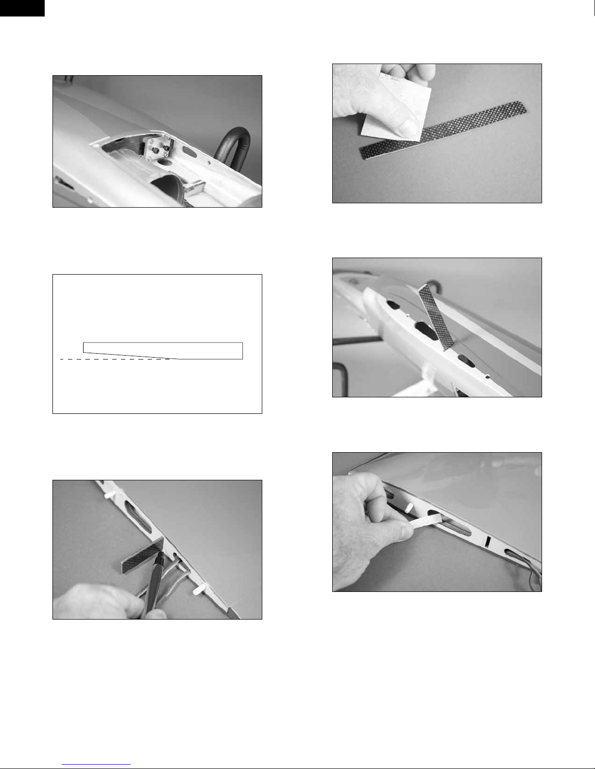
4. Use a ruler and pencil to draw two lines along on the outside of the
fan housing to indicate the location of the fan fairing.
1. Locate the fan unit. View the fan unit and use the drawing provided to
determine the top and bottom of the fan. There will be a label on the top of
the fan unit to help identify the top. This label was not available during the
production of this manual. A piece of low-tack tape on the top of the fan is
shown so the top can easily be determined during assembly.
Mounting lug
Label
Mounting lug
Fan bottom (fuselage top)
Fan centerline
2. Pass the wires through the fan fairing.
5. Remove the fan fairing from the motor using a #1 Phillips
screwdriver. Slide the exhaust tube over the fan unit. The seam on the
tube will be toward the bottom of the fan. Use low-tack tape to tape the
tube to the fan unit temporarily. Transfer the lines on the housing to the
exhaust tube using a felt-tipped pen and ruler. Also make a mark at the
edge of the fan housing to locate the position of the tube on the housing.
41
Page 42

EN
6. Measure back 1/2-inch (13mm) and 15/8-inch (42mm) from where
the edge of the fan housing fits in the tube. Use these lines and those that
aligned with the fan fairing to draw a rectangle on the tube. Carefully draw
an airfoil shape that matches the fan fairing in the rectangle.
7. Use hobby scissors to trim the exhaust tube for the fan fairing. Slot
the exhaust tube so it can be slid over the fan fairing.
9. Fit the fan housing into the fuselage. You may need to remove the
elevator servo horns and loosen the screws holding the pushrod supports
to fit the fan into the fuselage. Slide the fan forward to make sure it is fully
inserted into the intake.
8. Repeat step 2 and 3 to reattach the fan fairing to the motor. Check
the fit of the exhaust tube on the fan unit. It may be necessary to trim the
opening slightly using hobby scissors.
10. Use a pin vise and 5/64-inch (2mm) drill bit to drill the four holes
for the fan mounting screws. Make sure to drill the holes against the tabs
of the housing so the fan does not slide forward or aft in the fuselage.
E-tips
You can also mount the pin vise in a drill so it can reach down inside the
fuselage saving some time when drilling the holes.
42
Page 43

11. Use a #1 Phillips screwdriver to thread a 3mm x 10mm selftapping screw into the four holes for mounting the fan unit.
EN
EXHAUST TUBE AND
SPEED CONTROL INSTALLATION
Required Parts
Fuselage assembly Exhaust tube
Clear tape Fan access hatch
Speed control Hook and loop tape
Required Tools and Adhesives
Hobby scissors Felt-tipped pen
Hemostats
1. Carefully roll or fold the exhaust tube into the shape shown below. It
is made of a durable clear plastic and will not be harmed by doing so.
12. Place 2–3 drops of thin CA in each hole to harden the surrounding
wood. This hardens the wood, making the screws more secure.
13. Secure the fan unit in the fuselage using four 3mm x 10mm selftapping screws. Tighten the screws using a #1 Phillips screwdriver.
2. Slide the exhaust tube into the fuselage, with the wider end of the
tube entering the fuselage from the rear. It will “pop” open when it has
been inserted fully into the fuselage.
3. Position the exhaust tube so it overlaps onto the fan assembly.
14. Install the elevator servo horn and pushrod support if it was moved to
install the fan housing in the fuselage. The tape can also be removed from
the bottom of the fan housing at this time.
43
Page 44

EN
4. Use clear tape to secure the thrust tube to the fan housing.
5. Use clear tape at the bottom of the thrust tube to secure the
tube at the rear of the fuselage.
E-tips
Matching the colors between the ESC and motor when they are connected results in the correct motor direction if using all E-flite components.
8. Connect the leads from the speed control to the leads from the
motor. Use a pair of hemostats to hold the leads from the motor while you
are plugging the leads from the controller into them.
9. Remove the backing from the hook and loop tape to mount the
speed control inside the fuselage. Make sure to secure the switch inside
the fuselage where it can be easily accessed using double-dated tape.
6. Route the leads from the motor through the oval opening at the
bottom of the former near the intake ducts. Use clear tape to tape the
leads to the fan housing and intake duct so they don’t move and interfere
with the operation of the elevator servos.
7. Cut a piece of hook and loop tape to fit the back of the speed control
using scissors. Apply the tape to the speed control as shown.
E-tips
Make sure to set the cutoff voltage of the speed control to match the cell
count of the battery.
44
Page 45

6-CHANNEL RECEIVER INSTALLATION
Required Parts
Fuselage assembly Harness from retract assembly
6-inch (152mm) Y-harness (2)
(flaps, ailerons)
3-inch (76mm) servo extension
(flaps)
9-inch (228mm) servo extension
(retracts)
Required Tools and Adhesives
Scissors String
NOTE: The following section is for installing the receiver in the Habu 32 for
a 5- or 6-channel operation depending on if you are using retracts or not.
This is the basic setup for the Habu 32 using Y-harnesses for all control
surfaces.
1. Prepare the aileron harness by securing a 12-inch (304mm)
extension to a 6-inch (152mm) Y-harness using string or a commercially
available connector. The 12-inch (304mm) extension will plug into the
aileron channel of the receiver.
3-inch (76mm) Y-harness
(steering/rudder)
6-inch (152mm) servo extension
(retracts)
12-inch (304mm) servo extension
(2) (flaps, ailerons)
EN
3. Insert the flap and aileron harnesses through the hole in front of the
elevator servo and into the fuselage. The leads will exit toward the top of
the fuselage above the intake. Secure the leads using tape or tie-wraps to
keep them from interfering with the operation of the elevator servos.
4. (Optional Retracts) Prepare the retract harness by securing a 6-inch
(152mm) and 9-inch (228mm) extension to the retract harness using
string or a commercially available connector. This will plug into the retract
channel of the receiver.
2. Prepare the flap harness by securing a 12-inch (304mm) extension
to a 6-inch (152mm) Y-harness using string or a commercially available
connector. The 12-inch (304mm) extension will plug into the aileron
channel of the receiver. Secure a 3-inch (76mm) extension to one side of
the Y-harness using string or a commercially available connector. Make
sure to mark the flap harness so it can be easily identified from outside
the fuselage when installing the wing panels.
5. Plug the leads for the elevator, ailerons, flaps, and speed control
into the receiver at this time. Plug a Y-harness into the rudder channel of
the receiver for the rudder and steering. All the extensions should now be
connected to the receiver. Use the following to connect the extensions to
the receiver:
45
Page 46

EN
6-CHANNEL RECEIVER ASSIGNMENTS
Throttle Speed Control
Aileron Ailerons (harness from step 1)
Elevator Elevator (Y-harness)
Rudder Rudder and Nose Gear Steering (Y-Harness)
Gear Gear (optional) (harness from step 4)
Aux 1 Flaps (harness from step 2)
E-tips
Programs for the Habu using the DX8 are available for download on the
Spektum website.
6. Use scissors to cut a small piece of hook and loop tape. Use the tape
to secure the receiver in the fuselage.
8. Route the lead for the retracts through the fuselage. Use a pair
of hemostats to hold the leads from the motor while you are plugging
the leads from the controller into them. Routing it through the tray
the nose gear is mounted to and along the bottom of the fuselage will
keep the installation clean. Secure any loose leads with tie wraps (not
included).
E-tips
Use a #1 Phillips screwdriver to remove the nose gear cover so there is
better access for routing the retract leads.
8-CHANNEL RECEIVER INSTALLATION
Required Parts
Fuselage assembly Harness from retract assembly
6-inch (152mm) Y-harness 3-inch (76mm) servo extension
(flaps)
6-inch (152mm) servo extension
(retracts)
12-inch (304mm) servo extension
(flaps)
9-inch (228mm) servo extension
(retracts)
18-inch (457mm) servo extension
(2) (ailerons)
7. Use scissors to cut a small piece of hook and loop tape. Use the tape
to secure the remote receiver in the fuselage.
Required Tools and Adhesives
Scissors String
NOTE: The following section covers the installation of a 7- or 8-channel
receiver. This allows you to optimize and fine-tune the feel of the Habu 32
by using separate aileron channels and also a separate channel for the
nose gear steering. It also allows you to set the nose gear up for separate
trimming and a high and low rate switch.
1. Prepare the flap harness by securing a 12-inch (304mm) extension
to a 6-inch (152mm) Y-harness using string or a commercially available
connector. The 12-inch (304mm) extension will plug into the aileron
channel of the receiver. Secure a 3-inch (76mm) extension to one side of
the Y-harness using string or a commercially available connector. Make
sure to mark the flap harness so it can be easily identified from outside
the fuselage when installing the wing panels.
46
Page 47

2. Insert the flap harnesses and one of the 18-inch (457mm)
extensions through the hole in front of the elevator servo and into the
fuselage on the right side as shown. Run the other 18-inch (457mm) servo
extension inside the hole on the left side of the fuselage. The leads will
exit toward the top of the fuselage above the intake. Secure the leads
using tape or tie-wraps to keep them from interfering with the operation of
the elevator servos.
E-tips
The 18-inch (457mm) servo extensions reach the wing roots for the
ailerons and keep the excess wire to a minimum. If you will be taking the
Habu 32 apart often, connect a 3-inch (76mm) servo extension to each
of the 18-inch (457mm) servo extensions to ease assembly.
EN
8-CHANNEL RECEIVER
ASSIGNMENTS FOR DX8
Throttle Speed Control
Aileron Right Aileron
Elevator Elevators (Y-harness)
Rudder Rudder
Gear Flaps (harness from step 1)
Aux 1 Left Aileron
Aux 2 Gear (optional) (harness from step 3)
Aux 3 Nose Gear Steering
3. (Optional Retracts) Prepare the retract harness by securing a 6-inch
(152mm) and 9-inch (228mm) extension to the retract harness using
string or a commercially available connector. This will plug into the retract
channel of the receiver.
4. Plug the leads for the rudder, elevator, ailerons, flaps, nose wheel
servo and speed control into the receiver at this time. All the extensions
should now be connected to the receiver.
E-tips
Programs for the Habu using the DX8 are available for download on the
Spektum website.
5. Use scissors to cut a small piece of hook and loop tape. Use the tape
to secure the receiver in the fuselage.
6. Use scissors to cut a small piece of hook and loop tape. Use the tape
to secure the remote receiver in the fuselage.
47
Page 48

EN
7. Route the lead for the retracts through the fuselage. Routing it
through the tray the nose gear is mounted to and along the bottom of the
fuselage will keep the installation clean. Secure any loose leads with tie
wraps (not included).
3. Secure the battery in the fuselage using the hook and loop strap.
Make sure the strap is not pinching any of the servo leads on the bottom
side of the battery tray.
CANOPY ASSEMBLY
E-tips
Use a #1 Phillips screwdriver to remove the nose gear cover so there
is better access for routing the retract leads. Replace after routing the
leads.
MOTOR BATTERY INSTALLATION
Required Parts
Fuselage assembly Hook and loop tape
Motor battery Hook and loop strap
Fan cover
Required Tools and Adhesives
Scissors Phillips screwdriver: #1
1. Apply the hook and loop tape to the bottom of the battery. This will keep
the battery from sliding in the fuselage which could change the center of
gravity.
Required Parts
Canopy Cockpit interior Pilot (optional) (PKZ4414)
Required Tools and Adhesives
Hobby scissors Clear tape
1. Locate the cockpit interior and use hobby scissors to trim the interior
along the inscribed line. Trim the interior a little outside the line so it can
be trimmed to fit to the canopy.
2. Place the interior in the canopy. It may be necessary to bend the
interior slightly to fit past the canopy frame.
2. Apply the mating hook and loop tape to the battery tray in the
fuselage.
48
Page 49

3. Use clear tape to secure the interior inside the canopy.
E-tips
You can add more detail to the Habu 32 cockpit by painting parts of the
cockpit with different colors so it looks more realistic.
EN
2. The recommended Center of Gravity (CG) location for your model is
15
/16 to 41/2 inches (100 to 115mm) back from the leading edge of the
3
wing as shown with the battery pack installed. Mark the location of the CG
on the top of the wing with a felt-tipped pen.
3. When balancing your model, support the plane inverted at the marks
made on the top of the wing with your fingers or a commercially available
balancing stand. This is the correct balance point for your model. Make
sure your model is assembled and ready for flight before balancing.
CENTER OF GRAVITY
Required Parts
Assembled airframe
Required Tools and Adhesives
Balancing stand Felt-tipped pen
CAUTION: Do not inadvertently skip this step or property damage
and injury could occur.
When balancing your model, adjust the motor battery as necessary so
the model is level or slightly nose down. This is the correct balance point
for your model. You should find the CG to be very close with the battery
installed as shown in this manual. Mark the location of the battery on the
battery tray using a felt-tipped pen so it can be returned to this position if
it is removed from your model.
After the first flights, the CG position can be adjusted for your personal
preference.
1. Attach the wings to the fuselage following the procedure outlined
earlier in this manual. Attach the fan cover to the fuselage using the
four 2mm x 8mm self-tapping screws removed earlier and a #1 Phillips
screwdriver.
Balancing Stand
E-tips
If you have installed retracts, balance your model with the gear down.
49
Page 50

EN
CONTROL THROWS
1. Turn on the transmitter and receiver of your model. Check the
movement of the rudder using the transmitter. When the stick is moved
right, the rudder should also move right. Reverse the direction of the servo
at the transmitter if necessary.
2. Check the movement of the elevator with the radio system. Moving
the elevator stick toward the bottom of the transmitter makes the airplane
elevator move up.
3. Check the movement of the ailerons with the radio system. Moving
the aileron stick right makes the right aileron move up and the left
aileron move down.
4. Use a ruler to adjust the throw of the elevator, ailerons and rudder.
Adjust the position of the pushrod at the control horn to achieve the
following measurements when moving the sticks to their endpoints.
NOTE: Use caution with high rates on the elevator and ailerons. High rates
are only used for snap and spin aerobatic maneuvers. Middle rates are
suggested for takeoff and landings. Low rates are suggested for standard
flight maneuvers. If your radio only has the option for two rates, use the
middle and low rates.
Aileron
High Rate Up 11mm 25% Expo
Down 11mm 25% Expo
Mid Rate Up 8mm 15% Expo
Down 8mm 15% Expo
Low Rate Up 7mm 10% Expo
Down 7mm 10% Expo
Elevator
High Rate Up 12mm 18% Expo
Down 12mm 24% Expo
Mid Rate Up 10mm 10% Expo
Down 10mm 12% Expo
Low Rate Up 8mm 5% Expo
Down 8mm 8% Expo
Rudder
High Rate Right 20mm 12% Expo
Left 20mm 12% Expo
Mid Rate Right 18mm 8% Expo
Left 18mm 8% Expo
Low Rate Right 15mm 5% Expo
Left 15mm 5% Expo
Flap
Mid/Take-Off 11mm
Flap Full/Landing 25mm
Flap–Elevator Mix
Mid/Take-Off 1mm down
Flap Full/Landing 2mm down
E-tips
The Habu does not always require full flaps for landing. We recommend
using full flaps for landings in no wind or light headwind situations. Use
half flaps for landings in strong headwinds or crosswinds.
Measurements are taken at the inner or widest point on the control
surface.
These are general guidelines measured from our own flight tests. You can
experiment with higher rates to match your preferred style of flying.
E-tips
Travel Adjust and Sub-Trims are not listed and should be adjusted according to each individual model and preference.
We highly recommend re-binding the radio system once all the control
throws are set. This will keep the servos from moving to their endpoints
until the transmitter and receiver connect.
PREFLIGHT
• Check Your Radio
• Before going to the field, be sure your batteries are fully charged
per the instructions included with your radio. Charge the transmitter
and motor battery for your airplane. Use the recommended charger
supplied with your particular radio system, following the instructions
provided with the radio. In most cases, the radio should be charged
the night before going out flying.
• Before each flying session, be sure to range check your radio. See your
radio manual for the recommended range and instructions for your radio
system. Each radio manufacturer specifies different procedures for their
radio systems. Next, run the motor. With the model securely anchored,
check the range again. The range test should not be significantly affected. If it is, don’t attempt to fly! Have your radio equipment checked
out by the manufacturer.
• Double-check that all controls (aileron, elevator, rudder and throttle)
move in the correct direction.
• Check the radio installation and make sure all the control surfaces are
moving correctly (i.e., the correct direction and with the recommended
throws).
• Check all the control horns, servo horns, and clevises to make sure they
are secure and in good condition.
FLYING YOUR MODEL
Now that you have finished your Habu 32 and it’s ready to go, make one
final check of a few things first.
• Is the main battery fully charged? Is the transmitter fully charged?
• Are dual rates and travel adjustments set for the first flight?
Remember the Habu 32 is very responsive and it is highly recommended
that you take off with middle rates and then switch to low rates right after
takeoff. Has the center of gravity been verified? Has the timer been set?
We recommend that the timer be set for 3 minutes on the first flight. After
3 minutes of flight this will still give you a good safety margin for a few
landing approaches. The Habu 32 will consistently give you 4+ minutes
of high-speed flight. If you use power management 6+ minutes is easily
achieved.
If the answer to all of these questions is yes, then you are ready for that
first flight. Only fly the Habu 32 at a sanctioned flying field as it is not
50
Page 51

a park flyer. Turn on the transmitter, plug in the flight battery, and turn
on the switch for the radio. Check all control surfaces and basic motor
operation. Check the motor at full throttle. Pick the model up and cycle
the retracts. If everything is working properly you are ready for flight.
Taxi the model onto the runway. Make a few taxi tests and get the nose
gear steering adjusted so the model rolls straight down the runway. For
your first flight leave the flaps up on takeoff until you are familiar with
the Habu 32. Set the dual rates to the middle position. If you have set the
rudder and steering up separately then you can also set the nose gear for
a lower rate.
Takeoff
While applying power slowly steer with the rudder to keep the model
straight. the Habu 32 should accelerate quickly. As the model gains flight
speed, you will want to rotate when you feel comfortable. The Habu 32 will
climb out at a nice angle of attack.
EN
RANGE TEST YOUR RADIO
Before each flying session, and especially with a new model, it is
important to perform a range check. It is helpful to have another person
available to assist during the range check. If you are using a Spektrum
transmitter, please refer to your transmitter’s manual for detailed
instructions on the range check process.
1. With the model resting on the ground, stand 30 paces (approximately
90 feet) away from the model.
2. Face the model with the transmitter in your normal flying position.
Be sure the throttle is in the full down position and plug the flight battery
into the speed control.
3. As you move the controls, watch to be sure the airplane’s motor
and controls operate smoothly. You should have total control of the
model at 30 paces (90 feet).
Trimming and Flight Characteristics
After takeoff, gain some altitude and retract the landing gear and switch
to low rates. Climb to a safe altitude and begin to trim the model. Once
you have the model trimmed you will want to get an idea of the flight
quality with the flaps down and the model slowed down. Slow the model
down to a little below half power and drop the flaps to the middle position.
Check the trim again and also note if the model needs any up or down
elevator compensation. At this time you may also need to come back up
on the power a little. Now try full flaps and note any other trim changes
at this time. The Habu 32 will fly very nicely with full flaps added and is
very predictable in this configuration. Drop the landing gear and switch
back to middle rates at this time to check the trim once again in landing
configuration. Once you are happy with this, retract the gear, pull the flaps
up, and switch back to low rates and start to enjoy the performance of
the Habu 32. You will find the model tracks very well through all aspects
of flight. From high-speed passes, inverted flight, loops, and point rolls,
you will be flying like a jet pilot in no time. Get a feel for all dual rates. The
high rates are only used for snap and spin maneuvers. Middle rates are for
takeoff and landings. Low rates are for normal and precision flight.
Landing
Remember to keep an eye on the radio timer. After 3 minutes on the
first flight it’s time to drop the flaps, the retracts, and set the rates in the
middle and start shooting a few approaches with the Habu 32. To set up
for landing, drop the flaps and retracts, set the rates to the middle position
and enter the downwind pattern for landing. If you are landing in higher
winds or cross winds use middle flaps instead of full flaps. Adjust power to
slow the plane down but keep flying speed. As you roll onto final approach
manage the power and begin to pull the nose up. The Habu 32 has a very
nice approach and decent rate. You will find that with the nose slightly
high you can control the final approach descent with power management.
The key to a great landing is to manage the power and elevator all the
way to the ground and set down lightly on the main landing gear. After a
few flights you will find the Habu can be set down lightly on the mains and
you can hold the nose wheel off balancing the model on the mains till it
slows and gently settle the nose. We hope you enjoy flying the
E-flite Habu 32
4. If control issues exist, call the appropriate Horizon Product Support
office or go to horizonhobby.com to find a local Spektrum distributor in
your country for service if using a Spektrum radio system.
DAILY FLIGHT CHECKS
1. Check the battery voltage of the transmitter battery. Do not fly
below the manufacturer’s recommended voltage. To do so can crash your
aircraft.
E-tips
When you check these batteries, ensure you have the polarities correct
on your expanded scale voltmeter.
2. Check all hardware (linkages, screws, nuts, and bolts) prior to each
day’s flight. Be sure that binding does not occur and that all parts are
properly secured.
3. Ensure all surfaces are moving in the proper manner.
4. Perform a ground range check before each day’s flying session.
5. Prior to starting your aircraft, turn off your transmitter, then turn it
back on. Do this each time you start your aircraft. If any critical switches
are on without your knowledge, the transmitter alarm will sound a warning
at this time.
6. Check that all trim levers are in the proper location.
7. All servo pigtails and switch harness plugs should be secured in the
receiver. Make sure the switch harness moves freely in both directions.
51
Page 52

EN
LIMITED WARRANTY
What this Warranty Covers
Horizon Hobby, Inc. (“Horizon”) warrants to the original purchaser
that the product purchased (the “Product”) will be free from defects
in materials and workmanship at the date of purchase.
What is Not Covered
This warranty is not transferable and does not cover (i) cosmetic damage,
(ii) damage due to acts of God, accident, misuse, abuse, negligence,
commercial use, or due to improper use, installation, operation or
maintenance, (iii) modification of or to any part of the Product, (iv)
attempted service by anyone other than a Horizon Hobby authorized
service center, or (v) Products not purchased from an authorized Horizon
dealer.
OTHER THAN THE EXPRESS WARRANTY ABOVE, HORIZON MAKES NO
OTHER WARRANTY OR REPRESENTATION, AND HEREBY DISCLAIMS ANY
AND ALL IMPLIED WARRANTIES, INCLUDING, WITHOUT LIMITATION, THE
IMPLIED WARRANTIES OF NON-INFRINGEMENT, MERCHANTABILITY AND
FITNESS FOR A PARTICULAR PURPOSE. THE PURCHASER ACKNOWLEDGES
THAT THEY ALONE HAVE DETERMINED THAT THE PRODUCT WILL SUITABLY
MEET THE REQUIREMENTS OF THE PURCHASER’S INTENDED USE.
Purchaser’s Remedy
Horizon’s sole obligation and purchaser’s sole and exclusive remedy shall
be that Horizon will, at its option, either (i) service, or (ii) replace, any
Product determined by Horizon to be defective. Horizon reserves the right
to inspect any and all Product(s) involved in a warranty claim. Service
or replacement decisions are at the sole discretion of Horizon. Proof of
purchase is required for all warranty claims. SERVICE OR REPLACEMENT
AS PROVIDED UNDER THIS WARRANTY IS THE PURCHASER’S SOLE AND
EXCLUSIVE REMEDY.
Limitation of Liability
HORIZON SHALL NOT BE LIABLE FOR SPECIAL, INDIRECT, INCIDENTAL
OR CONSEQUENTIAL DAMAGES, LOSS OF PROFITS OR PRODUCTION OR
COMMERCIAL LOSS IN ANY WAY, REGARDLESS OF WHETHER SUCH CLAIM
IS BASED IN CONTRACT, WARRANTY, TORT, NEGLIGENCE, STRICT LIABILITY
OR ANY OTHER THEORY OF LIABILITY, EVEN IF HORIZON HAS BEEN
ADVISED OF THE POSSIBILITY OF SUCH DAMAGES. Further, in no event
shall the liability of Horizon exceed the individual price of the Product
on which liability is asserted. As Horizon has no control over use, setup,
final assembly, modification or misuse, no liability shall be assumed nor
accepted for any resulting damage or injury. By the act of use, setup or
assembly, the user accepts all resulting liability. If you as the purchaser or
user are not prepared to accept the liability associated with the use of the
Product, purchaser is advised to return the Product immediately in new
and unused condition to the place of purchase.
please direct your email to productsupport@horizonhobby.com, or call
877.504.0233 toll free to speak to a Product Support representative. You
may also find information on our website at www.horizonhobby.com.
Inspection or Services
If this Product needs to be inspected or serviced, please use the Horizon
Online Service Request submission process found on our website or call
Horizon to obtain a Return Merchandise Authorization (RMA) number. Pack
the Product securely using a shipping carton. Please note that original
boxes may be included, but are not designed to withstand the rigors of
shipping without additional protection. Ship via a carrier that provides
tracking and insurance for lost or damaged parcels, as Horizon is not
responsible for merchandise until it arrives and is accepted at our facility.
An Online Service Request is available at http://www.horizonhobby.com
under the Support tab. If you do not have internet access, please contact
Horizon Product Support to obtain a RMA number along with instructions
for submitting your product for service. When calling Horizon, you will be
asked to provide your complete name, street address, email address and
phone number where you can be reached during business hours. When
sending product into Horizon, please include your RMA number, a list of
the included items, and a brief summary of the problem. A copy of your
original sales receipt must be included for warranty consideration. Be sure
your name, address, and RMA number are clearly written on the outside of
the shipping carton.
NOTICE: Do not ship Li-Po batteries to Horizon. If you have any issue
with a Li-Po battery, please contact the appropriate Horizon Product
Support office.
Warranty Requirements
For Warranty consideration, you must include your original sales
receipt verifying the proof-of-purchase date. Provided warranty
conditions have been met, your Product will be serviced or replaced free
of charge. Service or replacement decisions are at the sole discretion
of Horizon.
Non-Warranty Service
Should your service not be covered by warranty service will be
completed and payment will be required without notification or
estimate of the expense unless the expense exceeds 50% of the retail
purchase cost. By submitting the item for service you are agreeing to
payment of the service without notification. Service estimates are available
upon request. You must include this request with your item submitted
for service. Non-warranty service estimates will be billed a minimum of
½ hour of labor. In addition you will be billed for return freight. Horizon
accepts money orders and cashiers checks, as well as Visa, MasterCard,
American Express, and Discover cards. By submitting any item to Horizon
for service, you are agreeing to Horizon’s Terms and Conditions found on
our website http://www.horizonhobby.com/Service/Request/.
Law
These terms are governed by Illinois law (without regard to conflict of law
principals). This warranty gives you specific legal rights, and you may also
have other rights which vary from state to state. Horizon reserves the right
to change or modify this warranty at any time without notice.
Warranty Services
Questions, Assistance, and Services
Your local hobby store and/or place of purchase cannot provide warranty
support or service. Once assembly, setup or use of the Product has been
started, you must contact your local distributor or Horizon directly. This
will enable Horizon to better answer your questions and service you in
the event that you may need any assistance. For questions or assistance,
52
Page 53

WARRANTY AND SERVICE CONTACT INFORMATION
Country of Purchase Horizon Hobby Address Phone Number / Email Address
United States of
America
United Kingdom Horizon Hobby Limited Units 1-4 Ployters Rd
Germany Horizon Technischer
France Horizon Hobby SAS 14 Rue Gustave Eiffel
Horizon Service Center
(Electronics and engines)
Horizon Product Support
(All other products)
Service
4105 Fieldstone Rd
Champaign, Illinois, 61822 USA
4105 Fieldstone Rd
Champaign, Illinois, 61822 USA
Staple Tye
Harlow, Essex
CM18 7NS, United Kingdom
Christian-Junge-Str. 1
25337 Elmshorn, Germany
Zone d’Activité du Réveil Matin
91230 Montgeron
877-504-0233
Online Repair Request Visit: www.horizonhobby.com/
service
877-504-0233
productsupport@horizonhobby.com
+44 (0) 1279 641 097
sales@horizonhobby.co.uk
+04121 2655 100
service@horizonhobby.de
+33 (0) 1 60 47 44 70
infofrance@horizonhobby.com
PARTS CONTACT INFORMATION
Country of Purchase Horizon Hobby Address Phone Number / Email Address
United States Sales 4105 Fieldstone Rd
Champaign, Illinois, 61822 USA
United Kingdom Horizon Hobby Limited Units 1-4 Ployters Rd
Staple Tye
Harlow, Essex
CM18 7NS, United Kingdom
Germany Horizon Hobby GmbH Hamburger Str. 10
25335 Elmshorn, Germany
800-338-4639
sales@horizonhobby.com
+44 (0) 1279 641 097
sales@horizonhobby.co.uk
+49 4121 46199 60
service@horizonhobby.de
EN
COMPLIANCE INFORMATION FOR THE EUROPEAN UNION
Instructions for Disposal of WEEE by Users in the European Union
This product must not be disposed of with other waste. Instead, it is the user’s responsibility to dispose of their waste equipment by
handing it over to a designated collection point for the recycling of waste electrical and electronic equipment. The separate collection and
recycling of your waste equipment at the time of disposal will help to conserve natural resources and ensure that it is recycled in a manner
that protects human health and the environment. For more information about where you can drop off your waste equipment for recycling,
please contact your local city office, your household waste disposal service or where you purchased the product.
53
Page 54

EN
ACADEMY OF MODEL AERONAUTICS NATIONAL MODEL AIRCRAFT SAFETY CODE
A. GENERAL: A model aircraft is a non-human-carrying aircraft capable of sustained flight in the atmosphere. It may not exceed limitations of this code
and is intended exclusively for sport, recreation and/or competition. All model flights must be conducted in accordance with this safety code and any
additional rules specific to the flying site.
1. Model aircraft will not be flown:
(a) In a careless or reckless manner.
(b) At a location where model aircraft activities are prohibited.
2. Model aircraft pilots will:
(a) Yield the right of way to all man carrying aircraft.
(b) See and avoid all aircraft and a spotter must be used when appropriate. (AMA Document #540-D-See and Avoid Guidance.)
(c) Not fly higher than approximately 400 feet above ground level within three (3) miles of an airport, without notifying the airport operator.
(d) Not interfere with operations and traffic patterns at any airport, heliport or seaplane base except where there is a mixed use agreement.
(e) Not exceed a takeoff weight, including fuel, of 55 pounds unless in compliance with the AMA Large Model Aircraft program.
(AMA Document 520-A)
(f) Ensure the aircraft is identified with the name and address or AMA number of the owner on the inside or affixed to the outside of the model
aircraft. (This does not apply to model aircraft flown indoors).
(g) Not operate aircraft with metal-blade propellers or with gaseous boosts except for helicopters operated under the provisions of
AMA Document #555.
(h) Not operate model aircraft while under the influence of alcohol or while using any drug which could adversely affect the pilot’s ability to safely
control the model.
(i) Not operate model aircraft carrying pyrotechnic devices which explode or burn, or any device which propels a projectile or drops any object that
creates a hazard to persons or property.
Exceptions:
• Free Flight fuses or devices that burn producing smoke and are securely attached to the model aircraft during flight.
• Rocket motors (using solid propellant) up to a G-series size may be used provided they remain attached to the model during flight. Model rockets may
be flown in accordance with the National Model Rocketry Safety Code but may not be launched from model aircraft.
• Officially designated AMA Air Show Teams (AST) are authorized to use devices and practices as defined within the Team AMA Program
Document (AMA Document #718).
(j) Not operate a turbine-powered aircraft, unless in compliance with the AMA turbine regulations. (AMA Document #510-A).
3. Model aircraft will not be flown in AMA sanctioned events, air shows or model demonstrations unless:
(a) The aircraft, control system and pilot skills have successfully demonstrated all maneuvers intended or anticipated prior to the specific event.
(b) An inexperienced pilot is assisted by an experienced pilot.
4. When and where required by rule, helmets must be properly worn and fastened. They must be OSHA, DOT, ANSI, SNELL or NOCSAE approved or
comply with comparable standards.
B. RADIO CONTROL (RC)
1. All pilots shall avoid flying directly over unprotected people, vessels, vehicles or structures and shall avoid endangerment of life and
property of others.
2. A successful radio equipment ground-range check in accordance with manufacturer’s recommendations will be completed before the first flight of a
new or repaired model aircraft.
3. At all flying sites a safety line(s) must be established in front of which all flying takes place (AMA Document #706-Recommended Field Layout):
(a) Only personnel associated with flying the model aircraft are allowed at or in front of the safety line.
54
Page 55

(b) At air shows or demonstrations, a straight safety line must be established.
(c) An area away from the safety line must be maintained for spectators.
(d) Intentional flying behind the safety line is prohibited.
4. RC model aircraft must use the radio-control frequencies currently allowed by the Federal Communications Commission (FCC). Only individuals
properly licensed by the FCC are authorized to operate equipment on Amateur Band frequencies.
5. RC model aircraft will not operate within three (3) miles of any pre-existing flying site without a frequency-management agreement
(AMA Documents #922-Testing for RF Interference; #923- Frequency Management Agreement)
6. With the exception of events flown under official AMA Competition Regulations, excluding takeoff and landing, no powered model may be flown
outdoors closer than 25 feet to any individual, except for the pilot and the pilot’s helper(s) located at the flight line.
7. Under no circumstances may a pilot or other person touch a model aircraft in flight while it is still under power, except to divert it from striking an
individual. This does not apply to model aircraft flown indoors.
8. RC night flying requires a lighting system providing the pilot with a clear view of the model’s attitude and orientation at all times.
9. The pilot of a RC model aircraft shall:
(a) Maintain control during the entire flight, maintaining visual contact without enhancement other than by corrective lenses prescribed for the pilot.
(b) Fly using the assistance of a camera or First-Person View (FPV) only in accordance with the procedures outlined in AMA Document #550.
C. FREE FLIGHT
1. Must be at least 100 feet downwind of spectators and automobile parking when the model aircraft is launched.
2. Launch area must be clear of all individuals except mechanics, officials, and other fliers.
3. An effective device will be used to extinguish any fuse on the model aircraft after the fuse has completed its function.
Page 56

DE
HINWEIS
Alle Anweisungen, Garantien und anderen zugehörigen Dokumente können im eigenen Ermessen von Horizon Hobby, Inc. jederzeit geändert werden.
Die aktuelle Produktliteratur finden Sie auf horizonhobby.com unter der Registerkarte „Support“ für das betreffende Produkt.
Spezielle Bedeutungen
Die folgenden Begriffe werden in der gesamten Produktliteratur verwendet, um auf unterschiedlich hohe Gefahrenrisiken beim Betrieb dieses Produkts
hinzuweisen:
HINWEIS: Wenn diese Verfahren nicht korrekt befolgt werden, können sich möglicherweise Sachschäden UND geringe oder keine Gefahr von
Verletzungen ergeben.
ACHTUNG: Wenn diese Verfahren nicht korrekt befolgt werden, ergeben sich wahrscheinlich Sachschäden UND die Gefahr von schweren Verletzungen.
WARNUNG: Wenn diese Verfahren nicht korrekt befolgt werden, ergeben sich wahrscheinlich Sachschäden, Kollateralschäden und schwere
Verletzungen ODER mit hoher Wahrscheinlichkeit oberflächliche Verletzungen.
Nicht geeignet für Kinder unter 14 Jahren. Dies ist kein Spielzeug.
WARNUNG: Lesen Sie die GESAMTE Bedienungsanleitung, um sich vor dem Betrieb mit den Produktfunktionen vertraut zu machen. Wird das
Produkt nicht korrekt betrieben, kann dies zu Schäden am Produkt oder persönlichem Eigentum führen oder schwere Verletzungen verursachen.
Dies ist ein hochentwickeltes Hobby-Produkt. Es muss mit Vorsicht und gesundem Menschenverstand betrieben werden und benötigt gewisse mechanische Grundfähigkeiten. Wird dieses Produkt nicht auf eine sichere und verantwortungsvolle Weise betrieben, kann dies zu Verletzungen oder Schäden
am Produkt oder anderen Sachwerten führen. Dieses Produkt eignet sich nicht für die Verwendung durch Kinder ohne direkte Überwachung eines
Erwachsenen. Versuchen Sie nicht ohne Genehmigung durch Horizon Hobby, Inc., das Produkt zu zerlegen, es mit inkompatiblen Komponenten zu
verwenden oder auf jegliche Weise zu erweitern. Diese Bedienungsanleitung enthält Anweisungen für Sicherheit, Betrieb und Wartung. Es ist unbedingt
notwendig, vor Zusammenbau, Einrichtung oder Verwendung alle Anweisungen und Warnhinweise im Handbuch zu lesen und zu befolgen, damit es
bestimmungsgemäß betrieben werden kann und Schäden oder schwere Verletzungen vermieden werden.
Fliegen
Fliegen Sie nur in offenen Gegenden wo Sie Sicherheit garantieren können. Vorzugsweise sind dieses zugelassene Modellflugplätze. Beachten Sie lokale
Bestimmungen und Gesetze bevor Sie sich ein Flugfeld aussuchen.
einlaSS/impeller
Halten Sie Gegenstände die angesaugt werden können fern von Ein- und Auslass. Insbesondere lose Kleidung oder andere Gegenstände wie Stifte oder
Schraubendreher. Halten Sie besonders ihre Hände fern von Ein- oder Auslass, da Verletzungsgefahr besteht.
akku Warnungen
Das der Sbach 342 BNF beiliegende Akkuladegerät (EFLUC1007) wurde
speziell auf eine sichere Aufladung des Li-Po-Akkus ausgelegt.
ACHTUNG: Alle Anweisungen und Warnhinweise müssen genau
befolgt werden. Falsche Handhabung von Li-Po-Akkus kann zu Brand,
Personen- und/oder Sachwertschäden führen.
• Durch Handhaben, Aufladen oder Verwenden des inbegriffenen Li-PoAkkus übernehmen Sie alle mit Lithiumakkus verbundenen Risiken.
• Sollte der Akku beim Laden oder im Flug beginnen, sich auszudehnen
oder anzuschwellen stoppen Sie den Ladevorgang oder den Flug
unverzüglich. Ziehen Sie den Akkustecker, und bringen Sie den Akku in
eine sichere offene Gegend, weit weg von entflammbaren Materialien,
und beobachten Sie ihn mindestens 15 Minuten. Wird mit dem Aufladen
oder Entladen eines Akkus fortgefahren, der sich auszudehnen oder
anzuschwellen begonnen hat, kann dieses zu einem Brand führen.
• Um beste Ergebnisse zu erzielen, lagern Sie den Akku bei Raumtemperatur an einem trockenen Ort.
• Beim Transport oder vorübergehenden Lagern des Akkus sollte der Temperaturbereich zwischen 4°C und 49°C liegen. Bewahren Sie den Akku
bzw. das Modell nicht im Auto oder unter direkter Sonneneinstrahlung
auf. Bei Aufbewahrung in einem heißen Auto, kann der Akku beschädigt
werden oder sogar Feuer fangen.
• Laden Sie immer Li Po Akkus weit weg entfernt von brennbaren Materialien.
• KEINESFALLS EIN Ni-Cd- ODER Ni-MH-LADEGERÄT VERWENDEN. Wenn
der Akku nicht mit einem kompatiblen Ladegerät aufgeladen wird,
kann dieses einen Brand, der zu Personen- und/oder Sachwertschäden
führen kann, zu Folge haben.
• Unter Last sollten die Li-Po-Akkus nicht bis unter jeweils 3 V entladen
werden.
• Verdecken Sie niemals Warnhinweise mit Klettband.
• Lassen Sie niemals Akkus während des Ladens unbeaufsichtigt.
• Laden Sie niemals Akkus ausserhalb ihres sicheren Temperaturbereich.
• Laden Sie niemals beschädigte Akkus.
SicherheitShinWeiSe
• Überprüfen Sie vor jedem Start alle Ruder.
• Fliegen Sie ihr Modell nicht in der Nähe von Zuschauern oder Gegenden
in denen Sie Personen verletzen oder Eigentum beschädigen könnten.
• Fliegen Sie nicht bei ungünstigen Wetterbedingungen. Schlechte Sicht
kann Orientierungs- und Kontrollverlust zur Folge haben. Für das Fliegen bei Starkwind gilt gleiches.
• Verlassen Sie sich nicht auf Glück oder Zufälle. Sollten zu einen Zeitpunkt während des Fluges eine abnormale Reaktion beobachten, landen
Sie bitte unverzüglich und korrigieren die Ursache. Fliegen Sie nicht
weiter bis die Ursache geklärt ist.
• Sicherheit sollte niemals auf die leichte Schulter genommen werden.
• Fliegen Sie nicht in der Nähe von Stromleitungen.
56
Page 57

inhaltverzeichniS
DE
einleitung
Sicherheitshinweise ........................................56
Einleitung ................................................57
Spezifikationen ............................................57
Über diese Anleitung ........................................57
Lieferumfang .............................................58
Farben ..................................................58
Zubehör .................................................58
RC Ausstattung ............................................58
Motor Setup ..............................................58
Optional Zubehör ..........................................58
Optionales Einziehfahrwerk ...................................58
Optional AKKU. . . . . . . . . . . . . . . . . . . . . . . . . . . . . . . . . . . . . . . . . . . . .58
Benötigtes Werkzeug und Ausstattung ..........................59
Montage der Ruderhörner ....................................59
Einbau des Querruderservos ..................................61
Einbau der Klappenservos ...................................65
Einbau des Tragflächenverbinder ..............................69
Einbau festes Fahrwerk .....................................72
Montage elektrisches Einziehfahrwerk ..........................74
optionale Hauptfahrwerkstüren ................................78
Einbau des festen Bugrads ...................................80
Einbau des Einziehfahrwerkes ................................84
Einbau des Seitenruderservos. . . . . . . . . . . . . . . . . . . . . . . . . . . . . . . . .87
Einbau Höhenruder Holm ....................................89
Einbau der Höhenruderservos .................................91
Impeller Einbau ............................................94
Montage Schubrohr und Regler/ESC ............................97
Empfängereinbau 6 Kanal Empfänger ...........................98
Nutzen Sie die folgende Aufstellung als Anschlußplan ...............99
Empfängereinbau 8 Kanal Empfänger ..........................100
8-Kanal Empfänger Zuordnung für die DX8 .....................100
Akkueinbau .............................................101
Montage Kabinenhaube ....................................102
Der Schwerpunkt .........................................102
Ruderausschläge .........................................103
Vor dem Flug ............................................104
Fliegen des Modells .......................................104
Reichweitentest der Fernsteuerung ............................104
Täglicher Flug Check ......................................105
Garantie und Service Informationen ...........................105
Konformitätshinweise für die Europäische Union. . . . . . . . . . . . . . . . . .106
Garantie und Service Kontaktinformationen .....................106
Kundendienstinformationen .................................106
E-flite® bringt mit der Habu 32 Design und Performance auf ein bislang
unerreichtes Niveau.Entwickelt um den E-flite Delta-V
Impeller mit dem 2150 Kv DF 32 Brushless Motor, liefert das Modell
mit den E-flite 6S 5000 mAh Akku beindruckendenen Schub gänzlich
ohne störende Cheetah Holes. Das Resultat ist ein Sport EDF Jet ,der bei
selbst erfahrenen Jet Piloten für eine Gänsehaut sorgt. Als erster Jet der
Platinum Serie beeindruckt die Habu 32 mit einem Finish das ebenso
beeindruckend wie seine Leistung ist.
Der schlanke GFK Rumpf besitzt ein integriertes Höhenleitwerk und ist
bereits lackiert. Die voll beplankten Tragflächen und Leitwerke sind mit
Carbonholmen versehen und mit Ultra Cote bespannt. Die Ruder sind
bereits angeschlagen. Zusammen mit dem optional erhältlichen E-flite
Einziehfahrwerk (separat erhältlich) erhalten Sie so einen Sport Jet der
sich deutlich aus der Masse abhebt.
To register your product online, visit www.e-fliterc.com
®
32 80mm
SpeziFikationen
Spannweite 1030mm
Tragflächeninhalt 25.3 q/ dm
Länge 1250mm
Gewicht ohne Akku 2.35–2.50 kg
Gewicht mit Akku 3.20–3.35 kg
Über dieSe anleitung
Diese Anleitung ist in Kapitel unterteilt und macht damit den
Zusammenbau und evtl. Pausen leichter. Zu jedem Schritt haben wir
Kontrollkästchen hinzugefügt, die dabei helfen erledigte Arbeiten und zu
markieren. Schritte die mit einem Kreis () markiert sind werden einmal
ausgeführt, Schritte die mit zwei Kreisen ( ) markiert sind, zeigen
an dass dieser Schritt wiederholt werden muß, wie zum Beispiel für die
rechte und linke Tragflächenhälfte, zwei Servos etc...
Bevor Sie mit dem Bauen anfangen ist es eine gute Idee sich die
Bedienungsanleitung einmal komplett durchzulesen um sich mit dem
Bauvorgang vertraut zu machen. Nehmen Sie sich zum Bauen Zeit und
folgen bitte den Anweisungen.
57
Page 58

DE
lieFerumFang
Replacement Parts
EFL807501 Rumpf mit Klappen und Ruder
EFL807502 Tragfläche Links
EFL807503 Tragfläche Rechts
EFL807504 Höhenleitwerk
EFL807505 Kabinenhaube
EFL807506 Kunststoffteile
EFL807507 Schubrohr
EFL807508 Kleinteile
EFL807509 Gestängeset
EFL807510 Dekorbogen
EFL807511 Fahrwerksbeine
EFL807512 Fahrwerkshalter festes Fahrwerk
EFL807513 Bugfahrwerk fest.
EFLAW175 Aluminium Räder Set 13/4-inch (44.5mm) (3)
8-Kanal Empfänger Einbau:
SPMAR8000 AR8000 DSM2 8-Kanal Empfänger mit voller Reichweite
SPMSA4020 4020 Servos (8)
SPMA3050 3-inch (76mm) Servo Verlängerung (5)
SPMA3051 6-inch (152mm) Servo Verlängerung
SPMA3052 9-inch (228mm) Servo Verlängerung
SPMA3053 12-inch (305mm) Servo Verlängerung
SPMA3004 18-inch (457mm) ServoExtension (3)
SPMA3058 Y-Kabel (2)
HINWEIS: Die Verlängerungen sind den 8 Kanal Betrieb vorgesehen
(separater Querruder und Bugrad) und erfordern einen Mischer am Sender.
6-Kanal Empfänger Einbau
SPMAR6200 AR6200 DSM2 6-Kanal Empfänger mit voller Reichweite
SPMSA4020 Servos (8)
SPMA3050 3-inch (76mm) Servo Verlängerung (5)
SPMA3051 6-inch (152mm) Servo Verlängerung
SPMA3052 9-inch (228mm) Servo Verlängerung
SPMA3053 12-inch (305mm) Servo Verlängerung
SPMA3004 18-inch (457mm) Servo Verlängerung
SPMA3058 Y-Kabel (3)
EFLRYH3 3-inch (76mm) Y-Kabel , Ultraleicht
Farben
HANU871 Deep Red
HANU881 Silver
HANU77 Pearl Charcoal
zubehör
Durchmesser Hauptfahrwerk 44.5mm
Durchmesser Bug Fahrwerk 44.5mm
Flächenbolzen 8-32 x 1/4-inch
Leitwerksbolzen 3mm x 15mm
rc auSStattung
Sie benötigen mindestens einen 5 Kanal Sender und 8 Servos. Wir
empfehlen hier die Verwendung des quarzlosen störungssicheren DX8 2,4
Ghz DSM 8 Kanal Fernsteuersystem. Sollten Sie einen eigenen Sender
verwenden empfehlen wir die folgende Ausstattung:
Sollten Sie eine eigene DX8 oder einen anderen DSM2 Sender verwenden
benötigen Sie einen AR8000DSM2 8 Kanal Empfänger und 8 SPMSA
4020 Servos.
HINWEIS: Die gelisteten Verlängerungen für den Betrieb mit 6 Kanälen
erfordern Y- Kabel auf Klappen, Querruder, und Bugrad zu Seitenruder.
motor Setup
EFLM3032DFA DF32 Brushless Motor, 2150Kv
EFLDF32 Delta-V 32 80mm EDF
EFLA1080 80-Amp Pro SB Brushless Regler ESC
EFLB50006S30 5000mAh 6S 22.2V 30C Li-Po, 10AWG EC5
optional zubehör
EFLC3020 Celectra™ 200W DC Multi-Ladegerät
EFLA110 Power Meter
EFLAEC312 Ladekabel 12-inch,
PKZ4414 Pilot
optionaleS einziehFahrWerk
EFLG230 15–25 Elektrisches Einziehfahrwerk
optional akku
EFLB50006S50C 5000mAh 6S 22.2V 50C Li-Po, 10AWG EC5
THP50006SP45 5000mAh 6-Cell/6S 22.2V G4 Pro Power 45C Li-Po
Komplettes RC System
SPM8800 DX8 DSM2 8 Kanal
58
Page 59

benötigteS Werkzeug und
auSStattung
Tools & Equipment
Balancierständer Bohrer
Gaserstift Glasreiniger
Hobbyzange Mischbecher
Papiertücher Petroleum Gelee
Bohrmaschine Lineal
Seitenschneider Bindfaden
Schleiftrommel Klares Klebenband
Epoxy Bürste Flachfeile
Klemmen Klebeband mit niedriger Klebekraft
Mischersticks Stift
Phillips Schraubendreher Pinzette
Reinigungsalkohol Schleifblock
Zange Quadrat
Dreieck
Trim seal tool
Steckschlüssel:2,5mm , 9/64 inch Bohrer: 1/16-inch (1.5mm),
5/64-inch (2mm)
Sechskantschlüssel Hobbymesser mit 11 Klinge
Schleifpapier mittel
DE
montage der ruderhörner
Benötigte Teile
Rumpf Tragflächen (links, rechts)
Höhenruder (links, rechts) GFK Ruderhörner (7)
Benötigtes Werkzeug und Klebstoff
Faserstift Mischer Sticks
Klebeband mit geringer Klebkraft 5 Minuten Epoxy
Mischbecher Schleifpapier mittel
Vorbereitung des Arbeitsplatzes
Wir haben Klebeband mit geringer Klebekraft zur Fixierung von Querruder und Landeklappen verwendet.
1. Überprüfen Sie die Passung des Ruderhorn in dem
Schlitz im Querruder. Der Schlitz ist groß genug, so dass das Ruderhorn
bis zu Schrägung hinein paßt. Markieren Sie mit einem Faserstift den
hinteren und vorderen Punkt wo das Ruderhorn auf die Fläche trifft.
Klebstoffe
5 Minuten Epoxy PAAPT38
15 Minuten Epoxy MEUEPX15MIN
Sekundenkleber Aktivator PAAPT715
Kabinenhaubenkleber PAAPT56
Sekundenkleber CA PAAPT02
Sekundenkleber Medium PAAPT08
Sekundenkleber Dünnflüssig PAAPT42
Schraubensicherung
Vorbereitung des Arbeitsplatzes
Wir empfehlen die Habu 32 auf einer weichen Unterlage zu bauen.
Dieses kann ein Schaumständer, ein großes Stück Schaumstoff oder ein
dickes Frotteehandtuch sein.
Bei der Angabe von Richtungen (unten, oben ,links, rechts etc...) sind
diese immer aus dem Blick des im Cockpit sitzenden Piloten zu sehen.
Solange nicht anders dargestellt.
2. Kleben Sie mit Klebeband mit geringer Klebekraft die
Montagestellen der Querruder- und Landeklappenhörner mit 1mm Abstand
auch zur Markierung des letzten Schrittes ab.
59
Page 60

DE
3. Schleifen Sie mit mittleren Schleifpapier die Stellen
des Ruderhornes an, die in der Fläche verklebt werden.
4. Kleben Sie die Ruderhörner mit 5 Minuten Epoxy in
die Öffnungen für Klappen und Querruder ein. Nutzen Sie ein Rechteck um
die Ruderhörner rechtwinklig auszurichten. Überprüfen Sie auch ob die
vorderen und hinteren Kanten bündig aufliegen.
7. Schleifen Sie einen kleinen Winkel wie abgebildet in die
Ruderhörner des Höhenruders. Der Winkel dient zur Passung. Testen Sie
dieses und stellen sicher, dass das Ruderhorn nicht die Oberfläche des
Ruders stört.
8. Wiederholen Sie die Schritte 1–5 um die Ruderhörner in beide
Höhenruderhälften einzukleben.
5. Ziehen Sie nach gut 3 Minuten bevor das Epoxy
vollständig ausgehärtet ist vorsichtig das Klebeband ab. Diese erlaubt es
dem Klebstoff spaltfüllend heraus zu kommen. Achten Sie darauf, dass Sie
die Ruderhörner bei dem Abziehen des Klebebandes nicht berühren.
6. Wiederholen Sie die Schritte 1–5 um die Ruderhörner in
beide Höhenruderhälften einzukleben.
9. Wiederholen Sie die Schritte 1–5 um das Ruderhorn in das
Seitenruder einzukleben.
60
Page 61

einbau deS QuerruderServoS
Benötige Teile
Tragflächen , links und rechts Sender
Empfänger Empfängerakku
Silikonschlauch Metallgabelköpfe (4)
2mm Mutter (4) Servos mit Zubehör (2)
Servoverlängerungen 76mm (2) Gewindestangen 2mm x 25mm (2)
Hartholzblock 13mm x 10mm x
7mm (4)
Benötigtes Werkzeug und Klebstoffe
Lineal Zange
Bindfaden Sekundenkleber dünnflüssig
Mischbecher Bohrer
Schleifpapier mittel Phillips Schraubendreher #1
Hobbymesser mit 11 Klinge Stift
5 Minuten Epoxy Mischer Sticks
Bohrer 5/64 inch (2mm) Schleiftrommel
2mm x 8mm selbst- schneidene
Schrauben (8)
DE
2. Sichern Sie die 76mm Servoverlängerung mit einer Schnur oder
einem handelsüblichen Verbinder.
3. Wiederholen Sie Schritte 1 und 2 um das zweite Querruderservo
vorzubereiten.Bitte beachten Sie das die Servos gespiegelt eingebaut
werden.
Vorbereitung des Arbeitsplatzes
Bevor Sie mit dem Einbau beginnen empfehlen wir die Servos mit der
Fernsteuerung zu zentrieren. Sollten Sie einen Computersender verwenden, nutzen Sie einen neuen oder gelöschten Modellspeicher und
benennen ihn nach dem Modell. Binden Sie den Sender und Empfänger
nach der Bedienungsanleitung ihres Senders.
1. Bereiten Sie das Querruderservo durch einschieben der
Gummipuffer und Blechösen vor. Zentrieren Sie das Servo mit der
Fernsteuerung. Entfernen Sie mit dem Seitenschneider alle Arme von dem
Servohorn die das Servo im Betrieb behindern könnten.
4. Nehmen Sie bitte die Abdeckungen der Querruder- und
Landeklappenservoschächte ab. Legen Sie die Abdeckungen zur Seite.
Vorbereitung des Arbeitsplatzes
Die Querruderanlenkung wird in dem Loch angeschlossen das 10mm
von der Mitte entfernt ist. Siehe Abbildung.
61
Page 62

DE
5. Zeichnen Sie mit einem Stift zwei Linien auf der Abdeckung. Der
erste Linie 2, 5mm über der Unterkante. Die zweite Linie wie abgebildet
22mm von der Seite. Diese Markierung zentriert das Servohorn in der
Aussparung. Prüfen Sie dieses zur Sicherheit voher mit den von Ihnen
verwendeten Servos.
6. Schleifen Sie die 10mm x 7mm Fläche mit mittleren Schleifpapier
an. Der Block wird im nächsten Schritt verklebt.
8. Fräsen Sie eine kleine Ausbuchtung für das Servokabel in den
Holzblock. Überprüfen Sie die Passung für die Kabelführung.
7. Nutzen Sie 5 Minuten Epoxy um den 13mm x 10mm x 7mm Block
an die Klappe zu kleben. Achten Sie bitte darauf die 10 x 7mm Seite an
zu kleben. Lassen Sie den Kleber vollständig trocknen.
9. Positionieren Sie das Querruderservo mit den eingesetzten
Gummipuffern auf dem Holzblock. Markieren Sie mit dem Stift die Umrisse
des Servos für die Montage des zweiten Holzblocks.
10. Kleben Sie mit 5 Minuten Epoxy den zweiten Block auf die
Abdeckung. Vergessen Sie nicht den Block vorher anzurauen wie in Schritt
6 dargestellt.
62
Page 63

11.Positionieren Sie das Servo zwischen die beiden Blocks. Lassen
Sie einen kleinen Spalt, so dass Vibrationen des Rumpfes nicht gleich
direkt auf das Servo übertragen werden können. Markieren Sie mit einem
Stift die Bohrlöcher.
12. Bohren Sie mit einem 2mm Bohrer die Löcher für die
Befestigungsschrauben. Bitte achten Sie darauf, dass die Löcher nicht
größer als benötigt werden.
DE
14. Schrauben Sie das Servo mit den mitgelieferten Schrauben und
einem Phillips #1 Schraubendreher fest.
15. Geben Sie 2–3 Tropfen dünnflüssigen Sekundenkleber in
die Schraublöcher. Das härtet das umgebende Holz und macht die
Schraubverbindung sicherer.
13. Geben Sie 2 bis 3 Tropfen dünnflüssigen Sekundenkleber in
jedes Bohrloch. Tropfen Sie auch Kleber auf die Vorder- und Rückseite
des Blockes um das Holz zu härten. Dieses hält das Holz vom Splittern ab
wenn die Schrauben eingedreht werden.
Vorbereitung des Arbeitsplatzes
Verwenden Sie kein Aktivatorspray. Lassen Sie den Sekundenkleber
vollständig in das Holz eindringen und das Holz härten.
16. Knoten Sie die Schnur um das Ende des Querruderkabels.
Ziehen Sie das Kabel noch nicht durch die Tragfläche, dieses erfolgt später
zusammen mit dem Klappenservo.
63
Page 64

DE
17. Schrauben Sie die Servoabdeckung mit den vier 2mm x 8mm
Schrauben mit einem # 1 Phillips Schraubendreher fest.
18. Schneiden Sie mit einem Hobbymesser mit # 11 Klinge zwei 6mm
lange Stücke vom Silikonschlauch.
20. Entfernen Sie das Klebeband das die Querruder und
Landeklappen in Position hält. Zentrieren Sie mit dem Sender das
Querruderservo. Verbinden Sie den Gabelkopf mit dem inneren Loch des
Servohornes. Drehen Sie die Länge des Gestänges so, dass das Ruder und
Servo zentriert sind. Schieben Sie dann die Schlauchstücke als Sicherung
über die Gabelköpfe. Kontern Sie mit einer Zange die Muttern gegen die
Gabelköpfe.
21. Wiederholen Sie die Schritte 4– 20 um das zweite Querruderservo
und Anlenkung einzubauen.
Vorbereitung des Arbeitsplatzes
Verwenden Sie bei Metallverbindungen immer Schraubensicherungslack.
19. Montieren Sie die Querruderanlenkung mit den 2
Schlauchstücken die im Schritt davor gefertigt wurden, 2 mm Muttern,
zwei Gabelköpfen und einem 2 mm x 25mm Gewindestück. Die Länge der
Anlenkung wird im nächsten Schritt eingestellt.
64
Page 65

einbau der klappenServoS
Benötigte Teile
Tragflächen (Rechts und Links) Sender
Empfänger Metallgabelköpfe (4)
Gewindestange Silikonschlauch
2mm Mutter (4) Servo mit Zubehör (2)
Hartholzblock (4) 2mm x 8mm selbst-schneidene
Schrauben
Benötigtes Werkzeug und Klebstoffe
Lineal Zange
Band Sekundenkleber dünnflüssig
Mischbecher Bohrer
Klebeband mit geringer Klebkraft Schleiftrommel
Phillips Schraubendreher Hobbymesser mit 11 Klinge
Stift 5 Minuten Epoxy
Mischer Sticks Bohrer (2mm)
Dremel, Proxon o.ä
DE
2. Wiederholen Sie Schritt 1 um das zweite Klappenservo
vorzubereiten. Bitte beachten Sie das die Servos in die gleiche Richtung
zeigen.
3. Zeichnen Sie mit einem Stift zwei Linien auf der Abdeckung. Der
erste Linie 2, 5mm über der Unterkante. Die zweite Linie wie abgebildet
22mm von der Seite . Diese Markierung zentriert das Servohorn in der
Aussparung. Prüfen Sie dieses zur Sicherheit vorher mit den von ihnen
verwendeten Servos.
Vorbereitung des Arbeitsplatzes
Bei dem Zentrieren der Klappenservos stellen Sie den Weg senderseitig
auf 0% für die beiden Klappenpositionen ein. Dieses gilt für 2 und 3
Positionen Schalter.
1. Bereiten Sie das Klappenservo durch einschieben der
Gummipuffer und Blechösen vor. Zentrieren Sie das Servo mit der
Fernsteuerung. Entfernen Sie mit dem Seitenschneider alle Arme von dem
Servohorn die das Servo im Betrieb behindern könnten.
Vorbereitung des Arbeitsplatzes
Die Klappenanlenkung wird in dem Loch angeschlossen das 13mm von
der Mitte entfernt ist. Siehe Abbildung.
4. Schleifen Sie die 10mm x 7mm Fläche mit mittleren Schleifpapier
an. Der Block wird im nächsten Schritt verklebt.
65
Page 66

DE
5. Nutzen Sie 5 Minuten Epoxy um den 13mm x 10mm x 7mm Block
an die Abdeckung zu kleben. Achten Sie bitte darauf die 10 x 7mm Seite
an zu kleben. Lassen Sie den Kleber vollständig trocknen.
8. Kleben Sie mit 5 Minuten Epoxy den zweiten Block auf die
Abdeckung. Vergessen Sie nicht den Block vorher anzurauen wie in Schritt
6 dargestellt.
6. Fräsen Sie eine kleine Ausbuchtung für das Servokabel in den
Holzblock. Überprüfen Sie die Passung für die Kabelführung
9. Positionieren Sie das Servo zwischen die beiden Blocks. Lassen
Sie einen kleinen Spalt, so dass Vibrationen des Rumpfes nicht gleich
direkt auf das Servo übertragen werden können. Markieren Sie mit
einem Stift die Bohrlöcher.
10. Bohren Sie mit einem 2mm Bohrer die Löcher für die
Befestigungsschrauben. Bitte achten Sie darauf, dass die Löcher nicht
größer als benötigt werden.
7. Positionieren Sie das Querruderservo mit den eingesetzten
Gummipuffern auf dem Holzblock. Markieren Sie mit dem Stift die Umrisse
des Servos für die Montage des zweiten Holzblocks.
66
Page 67

11. Geben Sie 2 bis 3 Tropfen dünnflüssigen Sekundenkleber in
jedes Bohrloch. Tropfen Sie auch Kleber auf die Vorder- und Rückseite des
Blockes um das Holz zu härten. Dieses hindert das Holz vom Splittern,
wenn die Schrauben eingedreht werden.
DE
13. Geben Sie 2 - 3 Tropfen dünnflüssigen Sekundenkleber in
die Schraublöcher. Das härtet das umgebende Holz und macht die
Schraubverbindung sicherer.
Vorbereitung des Arbeitsplatzes
Markieren Sie das Klappenservo zur besseren Unterscheidung mit
einem Stück Klebeband.
14. Knoten Sie die Schnur um die Klappen und Querruderservos.
Ziehen Sie mit der Schnur beide Kabel aus der Fläche heraus.
Vorbereitung des Arbeitsplatzes
Verwenden Sie kein Aktivatorspray. Lassen Sie den Sekundenkleber
vollständig in das Holz eindringen und das Holz härten.
12. Schrauben Sie das Servo mit den mitgelieferten Schrauben und
einem Phillips #1 Schraubendreher fest.
Vorbereitung des Arbeitsplatzes
Kleben Sie mit Klebeband die beiden Stecker zusammen damit sie
leichter durch die Fläche zu ziehen sind.
67
Page 68

DE
15. Schrauben Sie die Klappenabdeckung mit den vier 2mm x 8mm
Schrauben mit einem # 1 Phillips Schraubendreher fest.
16. Schneiden Sie mit einem Hobbymesser mit # 11 Klinge zwei 6mm
lange Stücke vom Silikonschlauch.
18. Zentrieren Sie mit dem Sender das Klappenservo. Schließen
Sie den Gabelkopf in das äußere Loch des Servohornes an. Den zweiten
Gabelkopf schließen Sie am Klappenhebel am. Stellen Sie die Länge des
Gestänges so ein, dass sich die Klappe in mittlerer / Start Position von
11mm befindet. Haben Sie die Länge eingestellt, schieben Sie bitte die
Silikonschlauchstücke als Sicherung über die Gabelköpfe um sie vor
versehentlichen Öffnen zu schützen. Kontern Sie dann mit einer Zange die
Muttern gegen die Gabelköpfe.
19. Stellen Sie den Schalter am Sender auf die -Klappen eingefahren-
Position. Stellen Sie die Werte am Sender so ein, dass die Klappe mit dem
Querruder auf einer Linie liegt.
Vorbereitung des Arbeitsplatzes
Verwenden Sie bei Metallverbindungaen immer Schraubensicherungslack.
17. Montieren Sie die Klappenanlenkung mit den 2 Schlauchstücken
die im Schritt davor gefertigt wurden , 2 mm Muttern, zwei Gabelköpfen
und einem 2 mm x 25mm Gewindestück. Die Länge der Anlenkung wird
im nächsten Schritt eingestellt.
20. Stellen Sie den Schalter am Sender auf die -Klappen ausgefahren-
Position. Stellen Sie die ATV (Weg) Werte am Sender so ein, dass die
Klappe 25mm unter dem Querruder steht.
Vorbereitung des Arbeitsplatzes
Auf Grund von kleinen Unterschieden bei den Positionen von Servo und
Ruderhorn verbinden Sie noch nicht die andere Klappenseite wie in
Schritt 19 und 20 beschrieben. Prüfen Sie bitte erst den Weg damit sich
das Servo in der -Klappen eingefahren- Position nicht verklemmen
kann.
68
Page 69

21. Wiederholen Sie die Schritte von 3 bis 18 um das zweite
Klappensvero anzuschließen. Verbinden Sie das Klappenservo mit dem
Ruderhorn erst zu dieser Zeit.
22. Stellen Sie den Klappenschalter auf die Klappen eingefahren
Position. Verbinden Sie die Klappe mit dem Servo und justieren die
Gestängelänge so, dass das die Klappe in eingefahrener Position auf einer
Linie mit dem Querruder liegt.
einbau deS tragFlächenverbinder
Benötigte Teile
Rumpf Carbon Flächenverbinder
8-32 x 1/4-inch
Sechskantschraube (4)
Benötigtes Werkzeug und Klebstoffe
Klebeband mit geringer Klebekraft 15 Minuten Epoxy
Papiertücher Epoxybürste
Lineal Petroleum Gelee
Inbusschlüssel 9/64 inch Phillips Schraubendreher #1
Mischbecher Mischsticks
Reinigungsalkohol Schleifpapier mittel
Faserstift
1. Schrauben Sie mit dem #1 Phillips Schraubendreher die vier 2mm
x 8mm Schrauben der Impellerabdeckung los. Legen Sie die Abdeckung
und Schrauben zur Seite.
Tragfläche (rechts und links)
DE
Vorbereitung des Arbeitsplatzes
Die Ausrichtung der beiden Klappen in den drei möglichen Positionen:
Eingefahren, Mittel und Voll Ausgefahren erfordert ggfs. etwas Feineinstellung. Bitte achten Sie darauf, dass zu aller erst die beiden Servohörner in die gleiche Position auf dem Servokranz greifen.
2. Schieben Sie den Veriegelungshebel nach hinten und heben die
Kabinenhaube vom Rumpf. Die Kabinenhaube wird vorne von zwei Stiften
im Rumpf gehalten. Legen Sie die Kabinenhaube zur Seite, dass sie nicht
beschädigt wird.
69
Page 70

DE
3. Drehen Sie mit einem 9/64 Inbusschlüssel die vier 8-32 x 1/4
Schrauben in die Aluminiumhalter. Drehen Sie die Schrauben vorsichtig
nur etwas hinein und achten dabei das Aluminium Gewinde nicht zu
beschädigen.
4. Nehmen Sie den Flächenverbinder zur Hand. Legen Sie ihn auf
eine gerade Platte. Die Oberseite des Verbinder ist gerade, die Unterseite
weist eine Schräge wie in der Zeichnung dargestellt auf. Diese Schräge ist
wegen der V-Form der Tragfläche notwendig.
6. Nehmen Sie den Verbinder aus der Fläche. Schleifen Sie die
Vorder- und Rückseite mit mittleren Schleifpapier an.
7. Schieben Sie den Verbinder jetzt in den Rumpf. Er wird leicht in den
Rumpf bis zu der Markierung von Schritt 5 reingehen. Falls nicht könnten
die Schrauben die Sie in Schritt 3 rein gedreht haben im Weg sein und
müssen weiter gelöst werden.
Oben
Top
*Not to scale
* nicht
maßstabsgetreu
5. Schieben Sie den Carbon Verbinder mit der schmalen Seite zuerst
in den dafür vorgesehnen Schlitz in der Tragfläche. Stellen Sie sicher, dass
dabei die -Oben- Seite auch Oben ist. Der Verbinder ist einfach in die
Öffnung zu schieben, schieben Sie ihn nicht mit Kraft weiter als er normal
reingeht. Markieren Sie diese Stelle mit einem Faserstift.
8. Schieben Sie die Schnur für das Servokabel des
Einziehfahrwerkes etwas in die Fläche hinein, dass sie nicht im Weg ist.
70
Page 71

9. Überprüfen Sie die Passung der Fläche zum Rumpf. Die Fläche
muß sauber an den Rumpf passen, wenn der Verbinder in Fläche und
Rumpf ist. Achten Sie darauf, dass die Kabel von den Klappen und
Querrudern im Rumpf sind und bei dieser Kontrolle nicht stören.
10. Nehmen Sie die Fläche vom Rumpf. Tragen Sie eine kleine
Menge von Petroleum Gelee um den Schlitz des Flächenverbinders auf.
Das Gelee verhindert, dass Sie unbeabsichtigt in den folgenden Schritten
die Fläche mit dem Rumpf verkleben
DE
12. Streichen Sie mit einem Pinsel den Verbinder wo er in die Fläche
geht mit Epoxy ein.
13. Schieben Sie den Verbinder in den Schlitz der Tragfläche ein.
Stellen Sie sicher, dass er richtig herum in der Fläche sitzt. Wischen Sie
austretendes Epoxy mit einem Papiertuch und Reinigungsalkohol weg.
Vorbereitung des Arbeitsplatzes
Bitte lesen Sie zum Verständnis die nächsten Schritte vor dem Anmischen des 15 Minuten Epoxy durch, da sie während der Aushärtezeit
durchgeführt werden müssen.
11. Mischen Sie 15ml von 15 Minuten Epoxy an. Geben Sie Epoxy
mit einem Mischstäbchen in den Schlitz des Flächenverbinders.
Vorbereitung des Arbeitsplatzes
Epoxy wird aus dem Schlitz austreten. Sollte das nicht der Fall sein,
haben Sie nicht ausreichend Epoxy in den Schlitz zum kleben gegeben.
14. Bevor das Epoy ausgehärtet ist, schieben Sie die Tragflächen an
den Rumpf. Sie können die Befestigungsschrauben der Fläche mit einem
9/64 Inbusschlüssel etwas anziehen und die Tragfläche mit Klebeband
mit geringer Klebekraft an den Rumpf kleben bis das Epoxy vollständig
ausgehärtet ist.
15. Nehmen Sie die Tragfläche ab wenn das Epoxy vollständig
ausgehärtet ist. Wiederholen Sie die Schritte 4 bis 14 für die zweite
Tragfläche.
16. Ist das Epoxy bei beiden Tragflächen vollständig ausgehärtet,
entfernen sie sorgfältig das Petroleum Gelee mit Reinigungsbenzin und
einem Papiertuch.
71
Page 72

DE
einbau FeSteS FahrWerk
Benötigte Teile
Tragflächen (links und rechts) Alu Stellring mit Schraube
3,5mm (2)
Alu Distanzstück 3,5mm (2) Rad 13/4-inch (44.5mm) (2)
Radachse Adapter Set (2) Fahrwerksbeine Hauptfahrwerk
(links und rechts)
Fahrwerkshalter Hauptfahrwerk (2) 3mm x 14mm Senkschraube
selbstschneidend (8)
Benötigtes Werkzeug und Klebstoffe
Bohrer Schraubensicherung
Sekundenkleber dünnflüssig kleines Folienbügeleisen
Dreieck Bohrer 2mm
Inbusschlüssel: 1,5mm Phillips Schraubendreher # 1
Hobbymesser mit # 11 Klinge Flachfeile
HINWEIS: Sollten Sie ein Einziehfahrwerk einbauen springen Sie bitte zum
nächsten Kapitel: Einbau Einziehfahrwerk.
1. Entfernen Sie mit einem Hobbymesser mit # 11 Klinge die Folie
an den Fahrwerkshaltern. Lassen Sie an den Rändern 1mm der Folie
überstehen, die Sie dann mit den kleinen Folienbügeleisen oder Trimm
Werkzeug innen an die Kanten bügeln.
3. Spannen Sie einen 2mm Bohrer in die Bohrmaschine ein. Kleben
Sie 16mm vom Ende des Bohrers Klebeband als Markierung, damit Sie nicht
tiefer in das Holz bohren.
4. Bohren Sie durch die Befestigungslöcher der Fahrwerkshalter vier
Löcher in die Holzschienen.
2. Setzen Sie den Fahrwerkshalter in die Fläche ein. Die Folie könnte
hier etwas bei stören. Bitte achten Sie darauf, dass der Halter richtig auf
den Holzschienen aufliegt
5. Nehmen Sie den Fahrwerkshalter herraus. Schrauben Sie
mit einem #1 Phillips Schraubendreher 3m x 14 selbstschneidene
Senkkopfschrauben in die vorher gebohrten Löcher. Schrauben Sie die
Schrauben wieder heraus. .
72
Page 73

6. Geben Sie 2–3 Tropfen dünnflüssigen Sekundenkleber in jedes
Loch. Dieses härtet das Holz und macht die Schraubverbindung des
Fahrwerkhalters sicherer.
DE
9. Halten Sie bei ausgefahrenen Klappen ein Dreieck unten an die
Klappenkante und prüfen dann ob die Fahrwerksachse rechtwinklig dazu
ausgerichtet ist.(Siehe Abbildung). Falls nicht, kann es notwendig sein die
flachen Teile des Fahrwerks zur Ausrichtung etwas zu feilen.
Vorbereitung des Arbeitsplatzes
Verwenden Sie bei Metallverbindungen immer Schraubensicherungslack
um ein losvibrieren zu verhindern.
7. Schieben Sie das Fahrwerksbein in den Fahrwerkshalter.
Sichern Sie das Bein mit der Madenschraube, die Sie mit dem 1,5mm
Inbusschlüssel anziehen. Die Madenschraube zentriert die flache Seite des
Fahrwerksbeines im Halter und verhindert ein Verdrehen.
8. Setzen Sie den Fahrwerkshalter mit Bein ein. Die Achse des Halters
zeigt dabei zur Flächeninnenseite und die Feder nach hinten. Schrauben Sie
den Halter mit den vier 3mm x 14mm Senkschrauben mit einem # 1 Phillips
Schraubendreher fest
10. Nehmen Sie die Radadapter und stecken Sie in beide Seiten des
Rades.
11. Feilen Sie mit der Feile eine 6mm breite Fläche nah am Ende
des Fahrwerkdrahtes um der Madenschraube halt zu geben. Dieses soll
verhindern, dass sich das Rad löst.
73
Page 74

DE
Vorbereitung des Arbeitsplatzes
Die Enden der Achsen können einen leichten Grat aufweisen. Sollte
daher das Rad schwer zu montieren sein, müssen Sie diesen entfernen.
Verwenden Sie bei Metallverbindungen immer Schraubensicherungslack
um ein lösen zu verhindern.
12. Schieben Sie ein 3,5mm Alu Distanzstück auf die Achse,
dann das Rad mit den Adaptern. Zum sichern wird ein 3,5mm Stellring
aufgeschoben, der durch eine Madenschraube für 1,5mm Inbusschlüssel
befestigt wird.
montage elektriScheS
einziehFahrWerk
Benötigte Teile
Sender Empfänger
Empfänger Akku Tragfläche links und rechts
Servoverlängerung (76mm) (2) Alu Stellring mit Schraube
3,5mm (2)
Rad 13/4-inch (44.5mm) (2) Radachse Adapter Set (2)
Fahrwerksbeine Hauptfahrwerk
(links und rechts)
3mm x 14mm Senkschraube
selbstschneidend (8)
Benötigtes Werkzeug und Klebstoffe
Bohrer Schraubensicherung
Sekundenkleber dünnflüssig kleines Folienbügeleisen
Dreieck Bohrer 2mm
Inbusschlüssel: 1,5mm Phillips Schraubendreher # 1
Hobbymesser mit # 11 Klinge Flachfeile
Zange Faden
Fahrwerkshalter Hauptfahrwerk
elektr. (2)
13. Wiederholen Sie die Schritte 1 bis 12 um das 2. Fahrwerk und Rad
zu montieren.
1. Entfernen Sie mit einem Hobbymesser mit # 11 Klinge die Folie
an dem Fahrwerkschacht. Lassen Sie an den Rändern 1mm der Folie
überstehen, die Sie dann mit den kleinen Folienbügeleisen oder Trimm
Werkzeug innen an die Kanten bügeln.
2. Lösen Sie mit einem 1,5 mm Inbusschlüssel das Fahrwerksbein
von der Mechanik.
74
Page 75

3. Setzen Sie die Mechanik in die Fläche ein. Stellen Sie bitte sicher,
dass sie richtig auf den Holzsschienen aufliegt.
DE
6. Nehmen Sie die Mechanik heraus. Schrauben Sie mit einem #1
Phillips Schraubendreher 3m x 14 selbstschneidene Senkkopfschrauben in
die vorher gebohrten Löcher. Schrauben Sie die Schrauben wieder heraus.
7. Geben Sie 2–3 Tropfen dünnflüssigen Sekundenkleber in jedes
Loch. Dieses härtet das Holz und macht die Schraubverbindung des
Fahrwerkhalter sicherer.
4. Spannen Sie einen 2mm Bohrer in die Bohrmaschine ein. Kleben
Sie 16mm vom Ende des Bohrers Klebeband als Markierung, damit Sie nicht
tiefer in das Holz bohren.
5. Bohren Sie durch die Befestigungslöcher der Fahrwerkshalter vier
Löcher in die Holzschienen.
Vorbereitung des Arbeitsplatzes
Die Fahrwerksbeine sind für den Betrieb mit dem starren und Einziehfahrwerk vorgesehen. Diese Beine sind für das Gewicht und die
Geschwindigkeit der Habu ausgelegt. Nutzen Sie diese Beine daher auch
für das Einziehfahrwerk.
Verwenden Sie bei Metallverbindungen immer Schraubensicherungslack
um ein losvibrieren zu verhindern.
75
Page 76

DE
8. Schieben Sie die Fahrwerksbeine in die Mechanik. Sichern Sie
diese mit den Madenschrauben an den abgeflachten Seiten und einem
1,5 mm Inbusschlüssel. Bauen Sie beide Fahrwerke zusammen.
HINWEIS: Die erste Lieferung der EFL 15-25 Einziehfahrwerke wurde
nur mit einer Madenschraube zum Festschrauben geliefert. Dieses mag
ausreichend für leichte Modelle sein, die schweren wie die Habu 32 sollten
mit zwei Schrauben gesichert sein. Sollte Ihnen die beiden Schrauben
fehlen, können Sie diese aus dem starren Fahrwerk ausbauen.
9. Stecken Sie eine 76mm Servoverlängerung auf den Anschluß des
Einziehfahrwerkes und sichern diese mit einem Band oder Verbinder.
11. Ziehen Sie mit der Schnur die Verängerung durch die Fläche.
Entfernen Sie danach die Schnur.
12. Setzen Sie das Fahrwerk ein. Die Achse zeigt dabei zur
Flächenwurzel, die Feder zeigt zur Hinterkante der Tragfläche. Schrauben Sie
das Fahrwerk mit den 3mm x 14mm Senkschrauben mit einem #1 Phillips
Schraubendreher ein.
10. Knoten Sie die Schnur um das Ende der Verlängerung. Bitte
achten Sie dabei darauf die Schnur nicht aus Tragfläche zu ziehen.
13. Nehmen Sie die Radadapter und stecken Sie in beide Seiten des
Rades.
76
Page 77

14. Halten Sie bei ausgefahrenen Klappen ein Dreieck unten an die
Klappenkante und prüfen dann ob die Fahrwerksachse rechtwinklig dazu
ausgerichtet ist. (Siehe Abbildung) Falls nicht, kann es notwendig sein die
flachen Teile des Fahrwerks zur Ausrichtung etwas zu feilen.
15. Feilen Sie mit der Feile eine 6mm breite Fläche nah am Ende
des Fahrwerkdrahtes, um der Madenschraube halt zu geben. Dieses soll
verhindern, dass sich das Rad löst.
DE
16. Schieben Sie ein 3,5mm Alu Distanzstück auf die Achse,
dann das Rad mit den Adaptern. Zum sichern wird ein 3,5mm Stellring
aufgeschoben, der durch eine Madenschraube für 1,5mm Inbusschlüssel
befestigt wird.
Vorbereitung des Arbeitsplatzes
Verwenden Sie bei Metallverbindungen immer Schraubensicherungslack
um ein lösen zu verhindern.
Vorbereitung des Arbeitsplatzes
Die Enden der Achsen können einen leichten Grat aufweisen. Sollte
daher das Rad schwer zu montieren sein, müssen Sie diesen entfernen.
17. Das Fahrwerksbein sollte mit dem Stellring bündig sein. Falls
nicht, kürzen Sie mit einer kleinen Fräse das Bein auf entsprechende
Länge. Entfernen Sie dazu bitte unbedingt das Rad, da sonst das Lager
von der Hitze Schaden nehmen könnte.
77
Page 78

DE
18. Überprüfen Sie die Funktion mit der Fernsteuerung. Das
Fahrwerk sollte sauber in den Fahrwerksschacht einfahren. Falls nicht,
biegen Sie das Rad bitte vorsichtig bis es paßt.
2. Zeichnen Sie zwei Linien die 22mm und 65mm von dem oberen
Ende der Fahrwerkstüren entfernt sind. Diese Linien sind die Mittellinien
der Montageblöcke.
19. Wiederholen Sie die Schritte 1 bis 18 um das zweite Fahrwerk
einzubauen..
optionale hauptFahrWerkStÜren
Benötigte Teile
Tragflächen (links und rechts) Sender
Empfänger Empfängerakku
2mm x 8mm selbst schneidene
Schrauben
Fahrwerkstürblöcke (4)
Benötigtes Werkzeug und Klebstoffe
Kleinbohrmaschine
(Dremel Proxon o.ä)
Lineal Handbohrer
Kabinenhaubenkleber Phillips Schraubendreher #0
Schleiftrommel mittleres Schleifpapier
Stift Bohrer 1,5mm
Seitenschneider
HINWEIS: Der Einbau der Fahrwerkstüren ist optional und kann auch jeder
Zeit nach Fertigstellung durchgeführt werden.
Fahrwerkstüren (2)
Schleifblock
3. Bohren Sie mit dem Handbohrer vier 1,5mm Löcher auf der
Mittellinie die Sie in Schritt 2 gezeichnet haben. Die Löcher müssen wie
abgebildet 5mm von der Mitte entfernt sein.
4. Biegen Sie mit einem Lineal vorsichtig die Fahrwerkstür so dass
sie sauber an die Tragfläche paßt. Arbeiten Sie bitte hier sehr vorsichtig
und langsam damit keine Farbe abplatzt.
1. Markieren Sie mit einem Stift die Mitte der unlackierten Seite der
Fahrwerkstür.
78
Page 79

5. Schleifen Sie die Fahrwerkstürblöcke so, dass Sie wie abgebildet
an die Innenseite der Fahrwerkstüren passen. Arbeiten Sie hier bitte mit
dem Schleifblock und mittlererem. Schleifpapier. Stellen Sie beide Blöcke
fertig.
6. Zentrieren Sie den Holzblock auf den Linien und markieren mit
einem Stift durch die Bohrungen die Löcher auf dem Block.
DE
8. Verrunden Sie mit mittleren Schleifpapier die Rückseite
des Blockes. Das ist notwendig, damit das Fahrwerk vernünftig
einfahren kann und es zentriert das Fahrwerk wenn es ausgefahren ist.
9. Schrauben Sie mit einem #0 Phillips
Schraubendreher eine selbst schneidene Schraube in jedes der
Bohrlöcher. Schrauben Sie die Schraube wieder heraus.
7. Bohren Sie mit einem 1,5mm Bohrer die beiden
Befestigungslöcher in den Holzblock.
10. Geben Sie 2– 3 Tropfen Sekundenkleber in jedes
der Bohrlöcher. Das härtet das Holz und sichert die Verbindung zu den
Fahrwerkstüren.
11. Wiederholen Sie die Schritte 7 bis 10 für den zweiten Block.
79
Page 80

DE
12. Schrauben Sie die Fahrwerkstür mit vier 2mm x 8mm selbst
schneidenen Schrauben und einem #0 Phillips Schraubendreher an.
15. Fahren Sie das Fahrwerk mit der Fernsteuerung ein. Damit
stellen Sie den richtigen Winkel der Fahrwerkstür ein. Lassen Sie den
Kleber über Nacht trocknen und fahren dann das Fahrwerk wieder aus.
Vorbereitung des Arbeitsplatzes
Arbeiten Sie bei dem Abschleifen der Schrauben bitte langsam. Die
Schrauben erhitzen bei dem Schleifen und könnten die Fahrwerkstür
anschmelzen.
13. Verrunden Sie die Schrauben mit einem Seitenschneider und
einem Bohrschleifer. Sollten Sie das nicht machen könnte es sein, dass
sich das Fahrwerk nicht vernünftig einfahren läßt.
14. Schieben Sie die Fahrwerkstür so, dass sie mit dem Block an
der Feder aufliegt. Geben Sie etwas Kabinenhaubenkleber zwischen
Fahrwerkstür und Strebe. Drehen Sie die Tür etwas hin und her damit sich
der Kleber vernünftig verteilt
16.iederholen Sie die Schritte 1 bis 15 um die zweite Tür zu
installieren.
einbau deS FeSten bugradS
Benötigte Teile
Rumpf Bugrad
Empfänger Silikonschlauch
Empfänger Akku Metallgabelköpfe
Gewindestange 57mm Servo mit Zubehör
3mm x 8mm Inbuschrauben (4) Aluminium Stellring mit
Madenschrauben,3,5mm
Aluminium Distanzstück , 3 Rad (44,5mm)
Radachsenadapterset.
Benötigtes Werkzeug und Klebstoffe
Zange Seitenschneider
klares Klebeband Phillips Schraubendreher #1
Hobbymesser mit 11 Klinge Schraubensicherung
Inbusschlüssel: 1,5 , 2,5mm
1. Schrauben Sie mit einem #1 Phillips Schraubendreher die vier
2mm x 8mm Schrauben der Abdeckung heraus. Legen Sie Schrauben und
Abdeckung zur Seite, sie werden später benötigt.
80
Page 81

2. Schrauben Sie mit einem #1 Phillips Schraubendreher eine
Servoschraube in die vier Löcher der Lenkservobefestigung. Schrauben
Sie die Schraube nachdem Sie die Gewinde in das Holz geschnitten haben
wieder heraus. Der Ausschnitt für das Lenkservo ist der mittlere auf dem
Servobrett.
HINWEIS: Die beiden Servoöffnungen zur linken und rechten des
Lenkservos werden nicht benötigt.
3. Geben Sie 2–3 Tropfen dünnflüssigen Sekundenkleber in jedes Loch.
Das härtet das Holz und macht die Schraubverbindung des Lenkservos
sicherer.
DE
5. Bauen Sie das Lenkservo mit dem gelieferten Zubehör mit einem
#1 Phillips Schraubendreher ein. Der Servoabtrieb zeigt nach hinten zum
Heck.
6. Schneiden Sie mit einem Hobbymesser mit # 11 Klinge 6mm von
einem Silikonschlauch ab.
4. Setzen Sie die Gummidämpfer und Blechösen in die Servohalter
ein. Zentrieren Sie das Servo mit der Fernsteuerung. Entfernen Sie mit
dem Seitenschneider bis auf einen alle Arme die das Servo im Betrieb
behindern könnten.
Vorbereitung des Arbeitsplatzes
Die Anlenkung wird in das Loch des Servoarmes gesteckt dass 10mm
von der Mitte entfernt ist. (siehe Abbildung)
Vorbereitung des Arbeitsplatzes
Verwenden Sie bei Metallverbindungen immer Schraubensicherungslack
um ein lösen zu verhindern.
7. Schieben Sie den Silikonschlauch auf einen der Gabelköpfe.
Schrauben Sie eine 2mm Mutter auf beide Seiten des Gestänges dann
die Gabelköpfe. Schrauben Sie die Köpfe so weit auf das Gestänge, dass
die Gewinde auf der anderen Seite zu sehen sind. Kontern Sie dann das
Gestänge dann mit den Muttern.
81
Page 82

DE
8. Stecken Sie den Gabelkopf ohne Schlauch auf den Steuerarm.
Vorbereitung des Arbeitsplatzes
Schneiden Sie ein 13mm langes Stück vom Silikonschlauch ab und
schieben es auf einen 2,5mm Inbusschlüssel. Sie können dann die 3mm
Schraube in den Schlauch stecken und so bequem die Schraube zur
Fahrwerkssicherung anschrauben.
10. Nehmen Sie das Servohorn ab und montieren das Lenkgestänge.
Setzen Sie das Servohorn wieder auf und überprüfen ob die Lenkung
zentriert ist wenn das Servo zentriert ist. Schrauben Sie zum Kontern
die 2mm Mutter gegen die Gabelköpfe. Drücken Sie die Gabelköpfe mit
einer Zange zusammen und schieben das Silikonschlauchstück über
den Gabelkopf und schrauben das Servohorn mit einem #1 Phillips
Schraubendreher fest.
11. Setzen Sie die Abdeckung wieder auf und schrauben diese mit den
vier 2mm x 8mm Schrauben aus Schritt 1 wieder an.
Vorbereitung des Arbeitsplatzes
Verwenden Sie bei Metallverbindungen immer Schraubensicherungslack
um ein lösen zu verhindern.
9. Schrauben Sie den Fahrwerkshalter mit den vier 3mm x 8mm
Schrauben in den Rumpf ein.
Vorbereitung des Arbeitsplatzes
Kleben Sie die Abdeckung mit klaren Klebeband an den Rumpf um sie
zusätzlich zu sichern.
12. Nehmen Sie die Radadapter und stecken Sie in beide Seiten des
Rades.
82
Page 83

13. Feilen Sie am Ende des Fahrwerksbeines wie abgebildet eine 6mm
breite Abflachung für die Madenschraube des Stellringes.
DE
14. Schieben Sie ein 3,5mm Alu Distanzstück auf die Achse, dann
das Rad mit den Adaptern. Zum sichern wird ein 3,5mm Stellring
aufgeschoben der durch eine Madenschraube mit 1,5mm Inbusschlüssel
befestigt wird.
Vorbereitung des Arbeitsplatzes
Verwenden Sie bei Metallverbindungen immer Schraubensicherungslack
um ein lösen zu verhindern.
Vorbereitung des Arbeitsplatzes
Die Enden der Achsen können einen leichten Grat aufweisen. Sollte
daher das Rad schwer zu montieren sein, müssen Sie diesen entfernen.
83
Page 84

DE
einbau deS einziehFahrWerkeS
Benötigte Teile
Rumpf Bugrad EZFW
Empfänger Silikonschlauch
Empfänger Akku Metallgabelköpfe
Gewindestange 57mm Servo mit Zubehör
3mm x 8mm Inbuschrauben (4) Aluminium Stellring mit
Madenschrauben,3,5mm
Aluminium Distanzstück , 3 Rad (44,5mm)
Radachsenadapterset.
Benötigtes Werkzeug und Klebstoffe
Zange Seitenschneider
klares Klebeband Phillips Schraubendreher #1
Hobbymesser mit 11 Klinge Schraubensicherung
Inbusschlüssel: 1,5 , 2,5mm
1. Schrauben Sie mit einem #1 Phillips Schraubendreher die vier 2mm
x 8mm Schrauben der Abdeckung heraus. Legen Sie Schrauben und
Abdeckung zur Seite, sie werden später benötigt.
3. Geben Sie 2–3 Tropfen dünnflüssigen Sekundenkleber in jedes Loch.
Das härtet das Holz und macht die Schraubverbindung des Lenkservos
sicherer.
4. Setzen Sie die Gummidämpfer und Blechösen in die Servohalter
ein. Zentrieren Sie das Servo mit der Fernsteuerung. Entfernen Sie mit
dem Seitenschneider bis auf einen alle Arme die das Servo im Betrieb
behindern könnten.
2. Schrauben Sie mit einem #1 Phillips Schraubendreher eine
Servoschraube in die vier Löcher der Lenkservobefestigung. Schrauben
Sie die Schraube nachdem Sie die Gewinde in das Holz geschnitten haben
wieder heraus. Der Ausschnitt für das Lenkservo ist der mittlere auf dem
Servobrett.
HINWEIS: Die beiden Servoöffnungen zur linken und rechten des
Lenkservos werden nicht benötigt.
Vorbereitung des Arbeitsplatzes
Die Anlenkung wird in das Loch des Servoarmes gesteckt dass 10mm
von der Mitte entfernt ist. (siehe Abbildung)
5. Bauen Sie das Lenkservo mit dem gelieferten Zubehör mit einem
#1 Phillips Schraubendreher ein. Der Servoabtrieb zeigt nach hinten zum
Heck.
84
Page 85

6. Schneiden Sie mit einem Hobbymesser mit # 11 Klinge 6mm von
einem Silikonschlauch ab.
Vorbereitung des Arbeitsplatzes
Verwenden Sie bei Metallverbindungen immer Schraubensicherungslack
um ein lösen zu verhindern.
7. Schieben Sie den Silikonschlauch auf einen der Gabelköpfe.
Schrauben Sie eine 2mm Mutter auf beide Seiten des Gestänges dann
die Gabelköpfe. Schrauben Sie die Köpfe so weit auf das Gestänge, dass
die Gewinde auf der anderen Seite zu sehen sind. Kontern Sie dann das
Gestänge dann mit den Muttern.
DE
9. Verwenden Sie einen 1,5mm Inbusschlüssel um den Steuerarm
durch anziehen der Madenschraube auf dem unteren flachen Teil zu
sichern. Stellen Sie sicher, dass der Arm wie auf dem Foto abgebildet
aussieht.
10. Setzen Sie das Fahrwerksbein in die Mechanik ein und schrauben
die Madenschrauben mit einem 1,5mm Inbusschlüssel fest. Bitte achten
Sie darauf, dass die Madenschrauben mit den abgeflachten Stellen auf
einer Linie liegen.
8. Fahren Sie mit der Fernsteuerung das Bugrad ein. Lösen Sie mit
einem 1,5mm Inbusschlüssel die Madenschraube am Lenkarm und
Stellring um das Fahrwerksbein ab zu nehmen.
Vorbereitung des Arbeitsplatzes
Die Fahrwerksbeine sind für den Betrieb mit dem starren und Einziehfahrwerk vorgesehen. Diese Beine sind für das Gewicht und die
Geschwindigkeit der Habu ausgelegt. Nutzen Sie diese Beine daher auch
für das Einziehfahrwerk.
Verwenden Sie bei Metallverbindungen immer Schraubensicherungslack
um ein lösen zu verhindern.
11. Verbinden Sie den Gabelkopf ohne Schlauch mit dem Steuerarm
der Mechanik.
Vorbereitung des Arbeitsplatzes
Schneiden Sie ein 13mm langes Stück vom Silikonschlauch ab und
schieben es auf einen 2,5mm Inbusschlüssel. Sie können dann die 3mm
Schraube in den Schlauch stecken und so bequem die Schraube zur
Fahrwerkssicherung anschrauben.
Vorbereitung des Arbeitsplatzes
Verwenden Sie bei Metallverbindungen immer Schraubensicherungslack
um ein lösen zu verhindern.
85
Page 86

DE
12. Schrauben Sie den Fahrwerkshalter mit den vier 3mm x 8mm
Schrauben in den Rumpf ein.
15. Nehmen Sie die Radadapter und stecken Sie in beide Seiten des
Rades.
13. Nehmen Sie das Servohorn ab und montieren das Lenkgestänge.
Setzen Sie das Servohorn wieder auf und überprüfen ob die Lenkung und
Servo zentriert sind. Schrauben Sie zum Kontern die 2mm Mutter gegen
die Gabelköpfe. Drücken Sie die Gabelköpfe mit einer Zange zusammen
und schieben das Silikonschlauchstück über den Gabelkopf und schrauben
das Servohorn mit einem #1 Phillips Schraubendreher fest.
14.Setzen Sie die Abdeckung wieder auf und schrauben Sie mit den
vier 2mm x 8mm Schrauben aus Schritt 1 wieder an.
Vorbereitung des Arbeitsplatzes
Verwenden Sie bei Metallverbindungen immer Schraubensicherungslack
um ein lösen zu verhindern.
16. Feilen Sie am Ende des Fahrwerksbeines wie abgebildet eine 6mm
breite Abflachung für die Madenschraube des Stellringes.
Vorbereitung des Arbeitsplatzes
Kleben Sie die Abdeckung mit klaren Klebeband an den Rumpf um sie
zusätzlich zu sichern.
HINWEIS: Für alle Modellbauer die eine Bugfahrwerkstür
realisieren möchten ist eine Platte dem Kit beigelegt. Der Einbau
ist hier nicht dargestellt und bleibt Ihnen selbst überlassen. Die
Bugfahrwerkstür reduziert den Luftwiederstand und erhöht etwas die
Höchstgeschwindigkeit.
86
Vorbereitung des Arbeitsplatzes
Die Enden der Achsen können einen leichten Grat aufweisen. Sollte
daher das Rad schwer zu montieren sein müssen Sie diesen entfernen.
Page 87

17. Schieben Sie ein 3,5mm Alu Distanzstück auf die Achse, dann
das Rad mit den Adaptern. Zum sichern wird ein 3,5mm Stellring
aufgeschoben der durch eine Madenschraube für 1,5mm Inbusschlüssel
befestigt wird.
DE
einbau deS SeitenruderServoS
Benötigte Teile
Rumpf Metallgabelköpfe
Silikonschlauch Gewindestange
Muttern 2mm (2) Servo mit Zubehör
18 inch (457mm
Servoverlängerung)
Benötigtes Werkzeug und Klebstoffe
Schnur Schraubensicherung
Seitenschneider Zange
Philips Schraubendreher Pinzette
Dünnflüssiger Sekundenkleber
1. Sichern Sie die 457mm Servoverlängerung des Seitenruderservos
mit einer Schnur oder einem Verbinder.
18. Überprüfen Sie die Funktion des Bugfahrwerkes mit der
Fernsteuerung. Die Abdeckung ist zwar ab Werk schon vorgeschnitten, es
können jedoch noch kleine Anpassungen notwendig sein. Benutzen Sie
dazu ein Hobby Messer oder Trommelschleifer.
Vorbereitung des Arbeitsplatzes
Die Enden der Achsen können einen leichten Grat aufweisen. Sollte
daher das Rad schwer zu montieren sein müssen Sie diesen entfernen.
2. Zentrieren Sie das Servo mit der Fernsteuerung . Schneiden Sie mit
dem Seitenschneider jeden Arm bis auf einen ab.
Vorbereitung des Arbeitsplatzes
Die Anlenkung wird in das Loch des Servoarmes gesteckt dass 13mm
von der Mitte entfernt ist. (siehe Abbildung)
4. Nehmen Sie die Abdeckung des Seitenruders vom Rumpf ab. Legen
Sie diese beiseite, sie wird später gebraucht.
87
Page 88

DE
5. Schrauben Sie mit einem #1 Phillips Schraubendreher die beiden
Schrauben des Seitenruderservohalters los und legen den Halter zur Seite.
9. Führen Sie die Servokabel durch den Rumpf und die Öffnungen in
den beiden Spanten nach vorne Richtung Cockpit.
6. Geben Sie 2–3 Tropfen dünnflüssigen Sekundenkleber in jedes Loch.
Dieser härtet das Holz und macht die Verschraubung des Servohalters
sicherer.
7. Prüfen Sie die Passung des Servos. Aufgrund von
Fertigungstoleranzen kann es sein, dass Sie das Servo für eine
maßgenaue Passung mit Klebeband etwas breiter machen müssen.
8. Führen Sie die Servoverlängerung in den Rumpf. Danach können
Sie das Servo vorsichtig einsetzen. Arbeiten Sie hierbei vorsichtig.
Sichern Sie das Servo mit dem Halter, den Sie im Schritt vorher
herausgeschraubt haben.
10. Schneiden Sie mit einem Hobby Messer mit # 11 Klinge zwei 6mm
lange Stücke vom Silikonschlauch.
Vorbereitung des Arbeitsplatzes
Verwenden Sie bei Metallverbindungen immer Schraubensicherungslack
um ein lösen zu verhindern.
11. Schieben Sie die Silikonschlauchstücke auf beide Gabelköpfe.
Schrauben Sie die beiden Muttern auf die 57mm Gewindestange und drehen
wie abgebildet die Gabelköpfe auf die Gewindestange.
88
Vorbereitung des Arbeitsplatzes
Verwenden Sie bei Metallverbindungen immer Schraubensicherungslack
um ein lösen zu verhindern.
Page 89

12. Entfernen Sie das Klebeband, dass das Seitenruder an der Finne
fixiert. Montieren Sie die Anlenkung am Servo und Ruderhorn. Biegen
Sie die Anlenkung wie abgebildet, so dass die Anlenkung das Ruder bei
Vollausschlag nicht berührt. Zentrieren Sie die Anlenkung so dass das
Ruder und Servo bei Neutralstellung in der Mitte stehen. Schieben Sie den
Silikonschlauch über die Gabelköpfe und schrauben die 2mm Muttern zum
kontern gegen die Gabellköpfe.
13. Kleben Sie die Abdeckung mit klaren Klebeband wieder an. Prüfen
Sie die Ruderfunktion ob der Hebel ohne Berührung der Abdeckung läuft.
Hier kann etwas Nacharbeit erforderlich sein.
DE
1. Schieben Sie den Holm in den Rumpf ein. Sichern Sie den
Hom mit zwei 3mm x 15mm Inbusschrauben. Führen Sie ggfls. kleine
Anpassungen in der Rumpföffnung durch, dass sich der Holm ohne
Klemmen verschrauben läßt. Bitte beachten Sie dass der Holm bei
korrekter Montage nach unten zeigt.
einbau höhenruder holm
Benötigte Teile
Rumpf Höhenruderholm links und rechts
Inbusschrauben 3mm x 15mm Silikonschlauch
Benötigtes Werkzeug und Klebstoffe
15min Epoxy Papiertücher
Epoxy Bürste Lineal
Petroleum Gelee Klebeband mit geringer Klebekraft
Inbusschlüssel: 2,5mm Mischbecher
Mischersticks Steckschlüssel 2,5mm
Reinigungsalkohol Schleifpapier mittel
Faserstift Hobby Messer mit 11 Klinge
Vorbereitung des Arbeitsplatzes
Wenn Sie keinen passenden langen Inbusschlüssel haben verlängern Sie
ihren mit einem Holzstab und Klebeband.
2. Markieren Sie mit einem Faserstift die Stelle wo der Holm aus
dem Rumpf austritt.
89
Page 90

DE
3. chrauben sie den Holm mit einem 2,5 mm Inbusschlüssel los und
nehmen ihn aus dem Rumpf heraus. Prüfen Sie die Passung den Holmsin
dem Höhenleitwerk. Der Holm sollte leicht bis zur Markierung aus dem
letzten Schritt in das Leitwerk gehen.
4. Überprüfen Sie die Passung des Höhenruders zum Rumpf. Das
Ruder sollte mit dem eingeschraubten Holm sauber am Rumpf anliegen.
6. Schrauben Sie die beiden Tragflächen mit einem 9/64 Inbusschlüssel
an den Rumpf. Stellen Sie sich in 2–3 Meter Abstand hinter das Modell
und überprüfen ob der Abstand des Höhenruders zur Tragfläche gleich ist.
Falls nicht, müssen die Holme vorsichtig etwas verschliffen werden bis der
Abstand gleich ist.
Gleicher Abstand
Equal distance
7. Nehmen Sie den Holm aus dem Rumpf. Rauen Sie mit mittlereren
Schleifpapier die Vorder- und Rückseite des Teiles an das in das Ruder
geht.
5. Wiederholen Sie die Schritte 1 bis 4 um die Passung des anderen
Holm zu überprüfen.
8. Geben Sie eine dünne Schicht Petroleum Gelle um die Öffnung
des Holmes um eine versehentliches Festkleben bei dem nächsten
Arbeitsschritt zu vermeiden.
Vorbereitung des Arbeitsplatzes
Bitte lesen Sie zum Verständnis die nächsten Schritte vor dem Anmischen des 15 Minuten Epoxy durch , da sie während der Aushärtezeit
durchgeführt werden müssen.
90
Page 91

9. Mischen Sie ca 15ml des 15 Minuten Epoxy an. Geben Sie das
Epoxy mit dem Mischerstäbchen in die Öffnung des Höhenruderholmes.
10. Streichen Sie mit einem Pinsel Epoxy auf die Seite des Holm der
in das Höhneruder geht.
DE
12. Schieben Sie das Höhenruder in die Halterung am Rumpf bevor
das Expox ausgehärtet ist. Fixieren Sie das Höhenruder mit Klebeband
mit geringer Klebekraft. Überprüfen Sie nochmal den Sitz und die
Ausrichtung bevor der Kleber ausgehärtet ist.
13. Wiederhohlen Sie die Schritte 7 bis 12 um das zweite Ruder fertig
zu stellen.
14. Ist der Klebstoff vollständig ausgehärtet, schrauben Sie die
Tragflächen mit einem 9/64 Inbusschlüssel los. Nehmen Sie ebenfalls
die Höhenruder ab und reinigen Sie von Petroleumgeleeresten. Nutzen
Sie dazu Reinigungsalkohol und Papiertücher. Schrauben Sie dann die
Höhenruder wieder an.
11. Schieben Sie den Holm in das Höhenruder. Bitte achten
Sie darauf, dass er richtig herum in der Fläche ist. Wischen sie evtl:
austretenden Kleber vom Holm und Ruder mit einem Papiertuch und
Reinigungsalkohol weg.
Vorbereitung des Arbeitsplatzes
Epoxy wird aus dem Schlitz austreten. Sollte das nicht der Fall sein,
haben Sie nicht ausreichend Epoxy in den Schlitz zum kleben gegeben.
einbau der höhenruderServoS
Benötigte Teile
Rumpf Y - Kabel
2mm Muttern (4) Gestängehalter Boden + Seitenteile
(2)
2 x 8 mm selbst-schneidene
Schrauben (4)
Servo mit Zubehör (2) Metallgabelköpfe
Silikonschlauch
Benötigtes Werkzeug und Klebstoffe
Schnur Sekundenkleber mittel
Aktivatorspray Hobby Messer mit 11 Klinge
Pinzette Sekundenkleber
Schere Phillips Schraubendreher #1
1. Bereiten Sie das Höhenservo durch einschieben der Gummipuffer
und Blechösen vor. Zentrieren Sie das Servo mit der Fernsteuerung.
Entfernen Sie mit dem Seitenschneider bis auf einen alle Arme die das
Servo im Betrieb behindern könnten.
Gestängedraht 412mm (2)
91
Page 92

DE
Vorbereitung des Arbeitsplatzes
Die Anlenkung wird in das Loch des Servoarmes gesteckt dass 10mm
von der Mitte entfernt ist. (siehe Abbildung)
2. Wiederholen Sie die Schritte um das zweite Servo vorzubereiten.
Beide Servosrichtungen sind identisch.
Vorbereitung des Arbeitsplatzes
Die Schrauben der Höhenruderservos werden in einem kleinen Winkel
eingebaut, dass sie mit Schraubendreher zugänglich sind.
5. Bauen Sie das Höhenruderservo mit dem gelieferten Zubehör
ein. Der Servoabtrieb zeigt dabei nach vorne. Führen Sie das Servokabel
überhalb des Einlasses nach vorne.
6. Wiederhohlen Sie die Schritte 3 und 4 mit 2mm x 8mm
Schrauben und einem # 1 Phillips Schraubendreher um das Holz für den
Gestängehalter vorzubereiten. Lassen Sie den Sekundenkleber für eine
Minute in das Holz eindringen und verwenden dann Aktivatorspray um
sicherzugehen, dass der Kleber vollständig trocken ist, da er bei dem
Einbau etwas bewegt werden muß.
3. Schrauben Sie mit einem #1 Phillips Schraubendreher
eine Servoschraube in die vier Löcher der Höhenruderservobefestigung.
Schrauben Sie die Schraube nachdem Sie die Gewinde in das Holz
geschnitten haben wieder heraus.
4. Geben Sie 2-3 Tropfen dünnflüssigen Sekundenkleber in
jedes Loch. Dieser härtet das Holz und macht die Verschraubung des
Servohalters sicherer.
7. Bauen Sie den Gestängehalter aus dem Boden und den
beiden Seitenteilen (L1 und L2) zusammen. Bitte beachten: Die
Befestigungsbohrung von L2 ist näher am Halter. Der Halter muß richtig
zusammengebaut sein um mit dem Höhenruderservo in einer Linie zu
liegen.
92
Page 93

8. Schieben Sie den Halter auf die Höhenruderbowdenzughülle.
Schrauben Sie den Halter mit zwei 2mm x 8mm selbst -schneidenen
Schrauben fest. Schneiden Sie die Hülle hinter dem Halter (Richtung
Servo) ab.
DE
12. Schieben Sie den Silikonschlauch auf den Gabelkopf. Schrauben
Sie die 2mm Mutter und dann die den Gabelkopf auf die Gewindestange.
Verbinden Sie den Gabelkopf mit dem Servohorn.
9. Schneiden Sie mit einem Hobby Messer mit # 11 Klinge zwei
6mm lange Stücke vom Silikonschlauch.
Vorbereitung des Arbeitsplatzes
Verwenden Sie bei Metallverbindungen immer Schraubensicherungslack
um ein lösen zu verhindern.
10. Schieben Sie ein Stück Silikonschlauch auf den Gabelkopf.
Schrauben Sie eine Mutter auf das Gestänge und dann den Gabelkopf.
Vorbereitung des Arbeitsplatzes
Es kann hilfreich sein zum befestigen des Gabelkopfes das Servohorn
mit einem Phillips 1 Schraubendreher vom Servo zu lösen. Bitte achten
Sie darauf, dass das Servo zentriert und das Horn wie abgebildet bei
dem Aufsetzen im rechten Winkel ist.
13.Entfernen Sie das Klebeband vom Höhenruder. Verbinden Sie das
Ruderhorn mit dem Gabelkopf. Justieren Sie den Gabelkopf so das Ruder
und das Servohorn zentriert sind.
11. Schieben Sie das Gestänge von hinten in das
Bowdenzugröhrchen ein.
Vorbereitung des Arbeitsplatzes
Verwenden Sie bei Metallverbindungen immer Schraubensicherungslack
um ein lösen zu verhindern.
93
Page 94

DE
14. Wiederholen Sie die Schritte 3 bis 13 um das zweite
Höhenruderservo und Anlenkung zu montieren. Bauen Sie den
Gestängehalter aus dem Boden und den beiden Seitenteilen (L1 und L2)
zusammen. Bitte beachten: Die Befestigungsbohrung von L2 ist näher
am Halter. Der Halter muß richtig zusammengebaut sein um mit dem
Höhenruderservo in einer Linie zu liegen.
15. Sichern Sie das Y- Kabel zu dem Höhenruderservo mit einem Band
oder einem Verbinder.
impeller einbau
Benötigte Teile
Impeller Schubrohr
Rumpf Impeller Verkleidung
2mm x 6mm Maschinenschrauben
(2)
3mm x 10mm selbst schneidene
Schrauben (4)
Benötigtes Werkzeug und Klebstoffe
dünnflüssiger Sekundenkleber Klebeband mit geringer Klebekraft
Stift Lineal
Phillips Schraubendreher #1 Handbohrer
Faserstift Schrere
Bohrer 2mm
1. Nehmen Sie den Impeller zur Hand. Bitte sehen Sie sich die Zeichnung
um die Seiten des Impeller zu zuordnen. Auf der Oberseite des Impeller
befindet sich ein Etikett (Dieses Etikett ist hier durch einen Streifen
Klebeband dargestellt)
Mounting lug
Label
Mounting lug
Fan bottom (fuselage top)
Fan centerline
94
2. Führen Sie die Kabel durch die Impeller Verkleidung.
Page 95

3. Schrauben Sie die Verkleidung mit den beiden 2mm x 6mm
Maschinenschrauben mit einem # 1 Phillips Schraubendreher fest. Bitte
beachten Sie, dass die Verkleidung zur Unterseite des Impellers zeigt.
4. Markieren Sie die Position des Halters mit einem Stift und Lineal auf
dem Impellergehäuse.
DE
6. Messen Sie von dem Punkt wo das Schubrohr auf das Gehäuse trifft
einmal 13mm und 42mm. Nehmen Sie diese beiden Maße und die vorher
markierte Breite des Halters um ein Rechteck zu zeichnen aus dem Sie
das Profil des Halters zeichnen können. (siehe Abbildung)
7. Schneiden Sie mit einer Schere einen Schlitz in das Schubrohr und
schneiden dann die Form des Halters aus. Sie können so das Schubrohr
auf das Gehäuse schieben.
5. Schrauben Sie Verkleidung mit einem #1 Phillips Schraubendreher
ab. Schieben Sie das Schubrohr auf den Impeller. Die Naht des Schubrohrs
zeigt nach unten. Fixieren Sie das Schubrohr provisorisch. Übertragen
Sie die Markierung des Gehäuses mit einem Lineal und Faserstift auf
das Schubrohr. Markieren Sie auch das Ende des Schubrohres auf dem
Impellergehäuse.
Befestigungslasche
Impeller Unterseite (Rumpf oben)
Etikett
Befestigungslasche
Impeller Mittellinie
8. Wiederholen Sie die Schritte 2 und 3. Überprüfen Sie die Passung
des Schubrohrs. Nehmen Sie ggfls. kleine Anpassungen vor.
95
Page 96

DE
9. Setzen Sie den Impeller im Rumpf ein. Es kann notwendig sein,
dass Sie dazu die Servohörner der Höhenruderservos abnehmen und die
Schrauben der Halter lösen müssen. Schieben Sie den Impeller ganz nach
vorne um sicher zu stellen, dass er richtig im Einlaß sitzt.
11. Schrauben Sie mit dem # 1 Phillips Schraubendreher eine der
3mm x 10mm Schrauben in die vier Löcher der Impellerbefestigung.
12. Geben Sie 2-3 Tropfen dünnflüssigen Sekundenkleber in die Löcher
um das Holz zu härten. Das sichert die Verbindung.
10. Drehen Sie mit den 2mm Bohrer vier Löcher durch die Halter in das
Holz.
Vorbereitung des Arbeitsplatzes
Sie könne auch den Handbohrer in einen Akkuschrauber einspannen.
13. Schrauben Sie den Impeller mit 4 x 10mm selbst schneidenen
Schrauben fest.
14. Schrauben Sie, falls Sie es entfernt haben, das Höhenruderservo und
den Gestängehalter wieder an.
96
Page 97

montage Schubrohr und regler/eSc
Benötigte Teile
Rumpf Schubrohr
Regler Rumpfklappe Impeller
Benötigtes Werkzeug und Klebstoffe
Schere Klebeband
Klettband Faserstift
Klemmen
1. Rollen oder drücken Sie vorsichtig das Schubrohr in die gezeichnete
Form. Das Schubrohr ist aus flexiblen Kunstststoff hergestellt und wird
davon nicht beschädigt.
DE
4. Befestigen Sie das Schubrohr mit klaren Klebeband.
5. Befestigen Sie das Ende des Schubrohres mit klarem
Klebeband.
2. Schieben Sie das so gerollte Schubrohr mit der größereren Seite
zuerst in den Rumpf. Sie hören ein “Plop” wenn es sich im Rumpf
entfaltet.
3. Positionieren Sie den Schlitz so dass er den Halter überlappt.
6. Führen Sie die Motorkabel durch die ovale Öffnung nach vorne.
Befestigen Sie die Kabel sicher mit klaren Klebeband.
7. Schneiden Sie ein Stück Klettband zurecht und kleben es wie
abgebildet. auf den Regler.
97
Page 98

DE
Vorbereitung des Arbeitsplatzes
Verbinden Sie bei E-Flite die Kabel des Motors und Reglers farblich passend, dreht der Motor in die richtige Richtung.
8. Verbinden Sie die Motor- mit den Reglerkabeln. Nehmen Sie dabei
Klemmen zur Hilfe die die Motorkabel halten.
9. Ziehen Sie das Abdeckpapier des Klettbandes vom Regler ab und
befestigen ihn im Rumpf. Stellen Sie sicher, dass der Schalter an einer
gut zu erreichenden Stelle mit Doppelklebeband im Rumpf placiert ist.
empFängereinbau 6 kanal
empFänger
Benötigte Teile
Rumpf Fahrwerkskabel
6-inch (152mm) Y-Kabel (2)
(Klappen Querruder)
3-inch (76mm)
Servokabelverlängerung (Klappen)
9-inch (228mm)
Servokabelverlängerung (Fahrwerk)
Benötigtes Werkzeug und Klebstoffe
Schere Band
HINWEIS: Das folgende Kapitel beschreibt den Einbau eines 5 oder 6
Kanal Empfängers (6 Kanal mit Einziehfahrwerk) in die Habu 32. Als Basis
Setup erfolgt hier die Ansteuerung der Ruder über Y- Kabel.
1. Bereiten Sie das Querruderanschlußkabel mit dem 6-inch (152mm)
Y-Kabel und der 12-inch (304mm) Verlängerung vor. Die 304mm
Verlängerung wird in den Querruderanschluß des Empfängers gesteckt.
3-inch (76mm) Y-Kabel
(Bugfahrwerk/Ruder)
6-inch (152mm)
Servokabelverlängerung (Fahrwerk)
12-inch (304mm)
Servokabelverlängerung (2)
(Klappen, Querruder)
Vorbereitung des Arbeitsplatzes
Stellen Sie sicher, dass die Niederspannungsabschaltung des Reglers mit
der Zahl der eingesetzten Zellen übereinstimmt.
2. Bereiten Sie das Klappenanschlußkabel mit dem 6-inch (152mm)
Y-Kabel und der 12-inch (304mm) Verlängerung vor. Die 304mm
Verlängerung wird in den Klappenanschluß des Empfängers gesteckt. Eine
3-inch (76mm) Verlängerung wird in die eine Seite des Y-Kabel gesteckt.
Sichern Sie alle Verbindungen mit einem Band oder einem Verbinder.
Markieren Sie das Klappenkabel, dass Sie es leichter bei der Montage der
Flächen zuordnen können.
98
Page 99

3. Führen Sie das Klappen- und Querruderkabel durch das Loch vor
dem Höhenruderservo in den Rumpf ein. Führen Sie das Kabel nach oben
über den Einlass. Sichern Sie die Kabel mit Klebeband oder Kabelbinder
um die Funktion der Höhenruderservo nicht zu behindern.
4. (optionales Einziehfahrwerk) Schließen Sie an das Kabel des
Einziehfahrwerkes eine 6-inch (152mm) und eine 9-inch (228mm)
Verlängerung an und sichern diese mit einem Band oder einem Verbinder.
Der Stecker kommt in den Fahrwerksanschluß des Empfängers.
DE
Vorbereitung des Arbeitsplatzes
Programmierungen der DX8 für die Habu32 stehen auf der Spektrum
Website zum Download bereit.
6. Schneiden Sie mit der Schere ein Stück Klettband ab und befestigen
damit den Empfänger im Rumpf.
7. Schneiden Sie mit der Schere ein zweites Stück Klettband ab und
befestigen damit den Satellitenempfänger im Rumpf.
5. Schließen Sie die Anschlüsse für Höhenruder, Querruder, Klappen
und den Regler an den Empfänger an:
nutzen Sie die Folgende auFStellung
alS anSchluSSplan
Throttle Regler
Aileron Querruder (Y Kabel von Schritt 1)
Elevator Höhenruder (Y-Kabel)
Rudder Seitenruder und Bugrad (Y-Kabel)
Gear Fahrwerk (optional) (Kabel von Schritt 4)
Aux 1 Klappen (Kabel von Schritt 2)
8. Hinweise zur Verkabelung: Führen Sie die Kabel des
Einziehfahrwerkes durch den Rumpf. Nutzen Sie zum anklemmen der
Motor- und Reglerkabel eine Klemme um die Motorkabel zu halten.
Wenn Sie die Kabel unten durch den Fahrwerksschacht führen
erhalten Sie eine saubere Installation. Sichern Sie alle losen Kabel mit
Kabelbindern (nicht im Lieferumfang).
Vorbereitung des Arbeitsplatzes
Sie kommen einfacher an die Kabel des Einziehfahrwerkes wenn Sie die
Abdeckung des Bugfahrwerks mit einem Phillips # 1 Schraubendreher
abschrauben.
99
Page 100

DE
empFängereinbau 8 kanal
empFänger
Benötigte Teile
Rumpf Fahrwerkskabel
6-inch (152mm) Y-Kabel 3-inch (76mm) Servoverlängerung
(Klappen)
6-inch (152mm)
Servoverlängerung (Fahrwerk)
12-inch (304mm)
Servoverlängerung (Klappen)
Benötigtes Werkzeug und Klebstoffe
Schere Band
HINWEIS: Das folgende Kapitel beschreibt den Einbau eines 7 oder
8 Kanals Empfängers. Diese Empfänger ermöglichen eine optimierte
und feinere Einstellung der Habu 32 auf den Querrudern und in der
Bugradsteuerung. Sie können mit dieser Einstellung das Bugrad separat
trimmen oder Dual Rate Einstellungen wählen.
1. Bereiten Sie das Klappenanschlußkabel mit dem 6-inch (152mm)
Y-Kabel und der 12-inch (304mm) Verlängerung vor. Die 304mm
Verlängerung wird in den Klappenanschluß des Empfängers gesteckt. Eine
3-inch (76mm) Verlängerung wird in die eine Seite des Y-Kabel gesteckt.
Sichern Sie alle Verbindungen mit einem Band oder einem Verbinder.
Markieren Sie das Klappenkabel, dass sie es leichter bei der Montage der
Flächen erkennen können.
9-inch (228mm)
Servoverlängerung (Fahrwerk)
18-inch (457mm)
Servolverlängerung (2) (Querruder)
Vorbereitung des Arbeitsplatzes
Die 18 inch (457mm) Servoverlängerungen reichen bis zu den Flügelwurzeln und reduzieren die freie Kabellänge auf ein Minimum. Sollten
Sie die Habu 32 öfter demontieren, verbinden Sie für ein einfacheres
Handling noch je eine 3 inch (76mm) Verlängerung an die 18 inch (457)
mm Servoverlängerung.
3. (optionales Einziehfahrwerk) Schließen Sie an das Kabel des
Einziehfahrwerkes eine 6-inch (152mm) und eine 9-inch (228mm)
Verlängerung an und sichern diese mit einem Band oder einem Verbinder.
Der Stecker kommt in den Fahrwerksanschluß des Empfängers.
4. Schließen Sie die Anschlüsse für Höhenruder, Querruder, Klappen
und den Regler an den Empfänger an.
8-kanal empFänger zuordnung FÜr
die dX8
2. Führen Sie das Klappenkabel und eine der18-inch (457mm)
Verlängerungen durch das Loch vor dem Höhenruderservo in den Rumpf
ein .Führen Sie das zweite 18 inch (457mm) Kabel auf der anderen
(linken) Seite ein und führen beide Kabel nach oben über den Einlass.
Sichern Sie die Kabel mit Klebeband oder Kabelbinder um die Funktion
der Höhenruderservos nicht zu behindern.
Throttle Regler
Aileron rechtes Querruder
Elevator Höhenruder (Y-Kabel)
Rudder Seitenruder
Gear Klappen (Kabel aus Schritt 1)
Aux 1 linkes Querruder
Aux 2 Fahrwerk (optional) (Kabel aus
Schritt 3)
Aux 3 Bugradsteuerung
100
Vorbereitung des Arbeitsplatzes
Programmierungen der DX8 für die Habu 32 stehen auf der Spektrum
Website zum Download bereit.
 Loading...