

Page 1
Cessna 182 370 ARF
Cessna, 182 Skylane, (associated emblems and logos, and
body designs of vehicles) are either registered trademarks or
trademarks of Textron Innovations, Inc. in the USA and/or
other countries, used under license by Horizon Hobby.
Assembly Manual
Page 2

Table of Contents
Introduction ................................................................2
Specifications .............................................................2
Contents of Kit/Parts Layout .........................................
Required Radio Equipment ...........................................
Important Information About Motor Selection .................
Sport Setup (stock gearbox) .........................................
High Power Setup (stock gearbox)* ..............................
Sport Outrunner Setup .................................................
High Power Outrunner Setup* ......................................
Optional Accessories ..................................................
Required Tools and Adhesives ......................................
Using the Manual .......................................................
Warning ....................................................................
Before Starting Assembly .............................................
Note on Lithium Polymer Batteries .................................
Warranty Information ..................................................
Landing Gear Installation ...........................................
Inrunner Mo
Outrunner Motor
Cowling Installation ..................................................16
Radio Installation ......................................................
Wing and Stabilizer Installation .................................
Battery Installation ....................................................
Control Throws .........................................................
Center of Gravity ......................................................
Range Testing the Radio ............................................28
Preflight ...................................................................29
2005 Official AMA
2
tor Installation .........................................11
Installation .......................................14
National Model Aircraft Safety Code .................
10
18
23
26
27
28
30
Introduction
Thank you for purchasing the Cessna 182 370 ARF
3
4
4
5
5
6
6
6
7
8
8
8
8
9
(EFL2200), a vacuum-formed model of the full-scale Cessna
182 Skylane. The Cessna features a vacuum-formed fuselage
and wing, scale details, and quick final assembly time,
making this a great scale park flyer choice for smooth stable
flights.
We provide a 5.33:1 gearbox and a 10 x 7 propeller so
you can easily add our E-flite™ Park 370 Inrunner Brushless
Motor, 4100Kv for exceptional performance. For a direct
drive alternative, try the E-flite Park 400 Outrunner, 920Kv
motor.
Specifications
Wingspan: 38 in (965mm)
Length: 30 in (760mm)
Wing Area: 215 sq in (14 sq dm)
Weight w/o Battery: 13–13.5 oz (370–380 g)
Weight w/ Battery: 15.5–17 oz (440–480 g)
Page 3
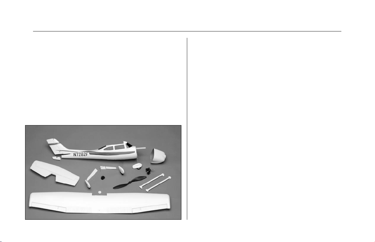
Contents of Kit/Parts Layout
Large Replacement Parts:
EFL2201 Main Wing w/Ailerons
EFL2202 Fuselage w/Rudder & Cowl
EFL2203 Horizontal Tail Assembly
EFL2204 Cowl
EFL2205 Landing Gear w/Wheel Pants
EFL2206 Wing Struts
EFL2207 Landing Gear Covers
EFL2208 Fuselage Tail Fairing
Small Replacement Parts
EFL2209 Pushrods
EFLA200 Micro Control Horns
EFLA201 Micro Pushrod Keepers
EFLA203 Micro Control Connectors
EFLA204 Micro Rubber Spinner
EFLA213 E-flite/JR/Horizon Decals
EFLM202 Pinion Gear, 12T 0.4 Module
EFLM216 Gearbox, 5.33:1 (v2)
EFLM217 Spur Gear, 64T w/Shaft
EFLP1070 10 x 7 Slow Flyer Prop (kit includes
only 1)
3
Page 4

Required Radio Equipment
You will need a 4-channel transmitter, crystals, micro
receiver, and four sub-micro servos. You can choose to
purchase a complete radio system that includes all of these
items or if you are using an existing transmitter, just purchase
the other required equipment separately.
JRP14010** JR Sport 4-CH System, MD2 UL
(NOTE: Still need two additional servos)
Complete Radio System
Or Purchase Separately
JSP30610 6CH UL FM Receiver w/o Crystal,
Positive Shift (JR/AIRZ)
Or
JSP30615 6CH UL FM Receiver w/o Crystal,
Negative Shift (HRC/FUT)
JRPXFR** FM Receiver Crystal
EFLRS75 7.5 gram Sub-Micro Servo (4)
JSP98020 Y-Harness, Standard 6"
JSP98110 Servo Extension 6"
Important Information About Motor
Selection
We are recommending the E-flite™ Park 370 Brushless
Motor with 4100Kv (EFLM1000) or the Park 400 Outrunner
Brushless Motor, 920Kv.
The Park 370 Brushless Motor, 4100Kv provides more than
awsome power with a 1200–1320mAh 3-cell Li-Po battery
or park flyer power with a 2-cell Li-Po battery. Just use the
included 5.33:1 gearbox and 10x7 propeller.
It is extremely important to monitor gearbox wear and motor
temperature when using the 4100Kv motor. Lack of proper
throttle management using this motor and a 3-cell Li-Po
battery may result in damage to the motor, gearbox, ESC,
and battery. Adequate motor cooling is very important, so
make sure the motor is cooled properly in the cowl.
For a direct-drive Outrunner alternative, use the Park 400
Outrunner, 920Kv, which will also provide plenty of power
without worrying about gearboxes.
4
Page 5

Sport Setup (stock gearbox)
High Power Setup (stock gearbox)*
EFLM1000 Park 370 Inrunner Brushless Motor,
4100 Kv
EFLA311B 20-Amp Brushless ESC (V2)
EFLP1070 10 x 7 Slow Flyer Prop (2) - keep
extras on hand
THP13202SPL 1320mAh 2-Cell 7.4V Li-Po, 16GA
WSD1300 Ultra Plug, Male/Female Set
EFLC3005 Celectra 1-3 Cell Li-Po Charger
Use with included 10 x 7 prop, 5.33:1 gearbox, and 12T
(0.4 module) pinion. This is a sport flyer setup for smooth
and stable flights.
EFLM1000 Park 370 Inrunner Brushless Motor,
4100 Kv
EFLA311B 20-Amp Brushless ESC (V2)
EFLP1070 10 x 7 Slow Flyer Prop (2) - keep extras
on hand
THP13203SPL 1320mAh 3-Cell 11.1V Li-Po, 16GA
WSD1300 Ultra Plug, Male/Female Set
EFLC3005 Celectra 1-3 Cell Li-Po Charger
* Use with included 10 x 7 prop, 5.33:1 gearbox, and
12T (0.4 module) pinion. Proper throttle management
is required when using high performance setups.
Using this setup with 3 cells will give you plenty of
power for zippy flights.
5
Page 6

Sport Outrunner Setup
High Power Outrunner Setup*
EFLM1305 Park 400 Outrunner Motor, 920 Kv
EFLA311B 20-Amp Brushless ESC (V2)
EFLM1915 Outrunner Stick Mount
EFLP1070 10 x 7 Slow Flyer Prop (2)
THP13202SPL 1320mAh 2-Cell 7.4V Li-Po, 16GA
WSD1300 Ultra Plug, Male/Female Set
EFLC3005 Celectra 1–3 Cell Li-Po Charger
This is a sport flyer setup for smooth and stable flights.
EFLM1305 Park 400 Outrunner Motor, 920 Kv
EFLA311B 20-Amp Brushless ESC (V2)
EFLM1915 Outrunner Stick Mount
EFLP1070 10 x 7 Slow Flyer Prop (2)
THP13203SPL 1320mAh 3-Cell 11.1V Li-Po, 16GA
WSD1300 Ultra Plug, Male/Female Set
EFLC3005 Celectra 1–3 Cell Li-Po Charger
* Proper throttle management is required when using high
performance setups. Using this setup with 3 cells will give
you plenty of power for zippy flights.
Optional Accessories
EFLA110 Power Meter
EFLA212 Gear Puller: 1mm–5mm Shaft
6
Page 7

Required Tools and Adhesives
Tools & Equipment
EFLA250 Park Flyer Tool Assortment, 5pc
Or Purchase Separately
EFLA257 Screwdriver, #0 Phillips (or included with
EFLA250)
EFLA255 Nut Driver, 5.5mm (or included with
EFLA250)
EFLA251 Hex Wrench: 3/32” (or included with
EFLA250)
Hobby Knife
Hot Glue Gun
Square
Ruler
Felt Tip Pen
Wax Paper
String
Adhesives
EFLA208 Thick Foam CA/Activator Pack
Or Purchase Separately
EFLA206 Foam Compatible Thick CA (included
with EFLA208)
EFLA207 Foam Compatible Activator (included
with EFLA208)
EFLA209 Foam Compatible Medium CA
Thread Lock (for mounting motor to gearbox)
Low Temperature Hot Glue
7
Page 8
Using the Manual
Before Starting Assembly
This manual is divided into sections to help make assembly
easier to understand, and to provide breaks between each
major section.
Remember to take your time and follow the directions.
Warning
An RC aircraft is not a toy! If misused, it can cause serious
bodily harm and damage to property. Fly only in open
areas, preferably at AMA (Academy of Model Aeronautics)
approved flying sites, following all instructions included with
your radio.
Keep loose items that can get entangled in the propeller
away from the prop, included loose clothing, or other objects
such as pencils and screwdrivers. Especially keep your hands
away from the propeller.
Before beginning the assembly of your Cessna 182, remove
each part from its bag for inspection. Closely inspect the
fuselage, wing panels, rudder and stabilizer for damage. If
you find any damaged or missing parts, contact the place of
purchase.
Note on Lithium Polymer Batteries
Lithium Polymer batteries are significantly
more volatile than alkaline or Ni-Cd/NiMH batteries used in RC applications. All
manufacturer’s instructions and warnings
must be followed closely. Mishandling of Li-Po
batteries can result in fire. Always follow the
manufacturer's instructions when disposing of
Lithium Polymer batteries.
8
Page 9

Warranty Information
Horizon Hobby, Inc. guarantees this kit to be free from
defects in both material and workmanship at the date of
purchase. This warranty does not cover any parts damaged
by use or modification. In no case shall Horizon Hobby’s
liability exceed the original cost of the purchased kit. Further,
Horizon Hobby reserves the right to change or modify this
warranty without notice.
In that Horizon Hobby has no control over the final assembly
or material used for the final assembly, no liability shall be
assumed nor accepted for any damage of or caused by the
final user-assembled product. By the act of using the product,
the user accepts all resulting liability.
Once assembly of the model has been started, you must
contact Horizon Hobby, Inc. directly regarding any warranty
question that you have. Please do not contact your local
hobby store regarding warranty issues, even if that is where
you purchased it. This will enable Horizon to better answer
your questions and provide service in the event that you may
need any assistance.
If the buyer or user is not prepared to accept the liability
associated with the use of this product, they are advised to
return this kit immediately in new and unused condition to
the place of purchase.
For any additional questions please contact:
Horizon Hobby Product Support
4105 Fieldstone Road
Champaign, Illinois 61822
(877) 504-0233
www.horizonhobby.com
9
Page 10
Landing Gear Installation
Required Parts
Fuselage
Landing gear
Landing gear fairing (2)
10mm x 136mm tape (2)
1. Locate the landing gear. Press the gear into the
slot in the bottom of the fuselage.
Note: The landing gear is designed for smooth
or paved surfaces. It is not recommended for
grass surfaces.
2. Use the 10mm x 136mm tape to attach the
landing gear fairings to the landing gear.
10
Page 11

Inrunner Motor Installation
Required Parts
Airframe 5.33:1 (64T spur) gearbox
Brushless motor Brushless speed control
2mm x 8mm screw (2)
12T pinion gear, 0.4 module x 6mm
Required Tools and Adhesives
Phillips screwdriver (small) Hobby knife
Hook & loop
Important Information about Your Brushless ESC
Make sure your ESC brake is programmed to Off. Also,
be sure to use an ESC with the proper 9V cutoff when
using 3-Cell Li-Po packs, or 6V cutoff when using 2-cell
Li-Po packs.
Note: This section covers the installation of an
Inrunner motor and gearbox. Skip to Page 12
for Outrunner Motor Installation.
1. It may be necessary to attach motor adapters or
other accessories to your particular motor at this
time.
Note: Use the instructions provided with the
motor to install any accessories. Follow the
instructions provided with the gearbox for some
helpful hints for installing the motor. When
installing your motor into the E-flite™ gearbox,
it is very important that the gear mesh is set
correctly and is smooth with no binding. The
E-flite gearbox features adjustable slotted
mounting holes to ensure your gear mesh is
correct. Remember if the gear mesh is too loose
or too tight, it may strip the gears. To extend
the life of your gearbox, we also recommend
using a small amount of grease, such as lithium
grease, on the spur gear.
It is also very important to check to be sure the
propeller is balanced before installing onto the
shaft. An unbalanced propeller may strip the
gears. When installing the propeller, please be
sure not to over-tighten the 3mm locknut. The
use of the locknut will prevent the propeller from
coming loose.
Use the 12-tooth pinion we include with this
airplane on the motor.
11
Page 12

2. Attach the motor to the gearbox using the screws
provided with the motor.
3. Slide the gearbox onto the motor stick. Use a
hobby knife to drill a hole through the plastic and
into the motor stick. Secure the gearbox using a
2mm x 8mm wood screw on the top and one or
even two in the side.
Hint: You may want to plug in the speed control
before installing the gearbox.
12
Page 13

4. Secure the speed control location using hook
and loop. Run the lead from the speed control to
the receiver. It may be necessary to use a servo
extension. Exact speed control location may vary
depending on the brand used and the center of
gravity. This photo shows the location in the front
of the fuse if you are using our E-flite™ 20-amp
Brushless ESC.
13
Page 14

Outrunner Motor Installation
Required Parts
Airframe
Brushless motor Brushless speed control
Outrunner Mount (EFLM1915 - sold separately)
2mm x 8mm wood screw (2)
Required Tools and Adhesives
Phillips screwdriver (small) Hobby knife
Hook & loop
Important Information about Your Brushless ESC
Note: It is also very important to check to be
sure the propeller is balanced before installing
onto the shaft.
2. When using the E-Flite™ outrunner motor and
mount, you will need to shorten the motor mount
stick by 13/16" (20mm). Use a razor saw to cut
the motor mount stick.
Make sure your ESC brake is programmed to Off. Also,
be sure to use an ESC with the proper 9V cutoff when
using 3-Cell Li-Po packs, or 6V cutoff when using 2-cell
Li-Po packs.
Note: This section covers the installation of an
Outrunner. Skip back to Page 10 for Inrunner
Motor Installation.
1. Attach the outrunner stick mount (EFLM1915 - sold
separately) to the outrunner motor at this time. Use
the hardware provided with your motor to attach it
to the mount using at minimum of two screws.
14
Page 15

3. Slide the motor mount and motor onto the motor
stick. Use a hobby knife to drill a hole through
the plastic and into the motor stick. Secure the
gearbox using a 2mm x 8mm wood screw. We
suggest adding one or two additional screws to
the sides on the outrunner stick mount.
Hint: You may want to plug in the speed control
before installing the motor mount.
4. Secure the speed control location using hook
and loop. Run the lead from the speed control to
the receiver. It may be necessary to use a servo
extension. Exact speed control location may vary
depending on the brand used and the center of
gravity. This photo shows the location in the front
of the fuse if you are using our E-flite™ 20-amp
Brushless ESC.
15
Page 16

Cowling Installation
Required Parts
Airframe Rubber spinner or propeller adapter
3mm locknut 3mm washer
10 x 7 propeller 2mm x 5mm screw (4)
Required Tools and Adhesives
Phillips screwdriver (small) Hobby knife
Hook & loop
1. Slide the cowling onto the fuselage, then the
propeller. Make sure there is clearance between
the cowling and propeller. Drill four locations for
the cowling screws.
Note: If you have selected the outrunner motor
option, install the propeller adapter onto the
motor shaft.
Note: The propeller will have to be drilled out
using a 15/64" drill when using the outrunner
motor and propeller adapter.
16
Page 17

2. Secure the cowling using four 2mm x 5mm
screws. Secure the propeller using the
3mm washer and 3mm locknut.
Note: Simply tighten the adapter when
using the outrunner and associated propeller
mounting hardware.
3. Press the spinner into position (if using the
Inrunner and gearbox option).
17
Page 18

Radio Installation
Required Parts
Fuselage
Wing
Micro control connector (5)
Control connector backplate (5)
2mm x 8mm screw (8)
Aileron servo cover (2)
3" linkage (2)
Y-harness, standard 6"
Servo extension 6"
Double-sided tape (2)
Required Tools and Adhesives
Phillips screwdriver (small)
Hobby knife
Hook & loop
String
Hot glue gun
1. Attach a micro control connector to the servo arm
for the elevator. Use the connector backplate to
secure the connector.
2. Plug the elevator servo into the receiver and
turn on the radio. Make sure the trim has been
centered, and then attach the servo arm to the
servo as shown.
18
Page 19

3. Repeat Steps 1 and 2 for the rudder servo, but
install two connectors instead of one.
4. Use hot glue to install the rudder and elevator
servos into the fuselage.
5. Pass the pushrods for the rudder and nose
wheel through the connectors. With the radio
on, physically center the rudder and nose wheel.
Tighten the screw in the connector to secure the
pushrod wires.
Note: Use the rudder trim for trimming flight
conditions. Do not use the trim if your plane
does not taxi straight. Loosen the screw in the
connector and change the position of the wire
to correct any taxi problems.
19
Page 20

6. Attach the receiver to the side of the fuselage
using a piece of hook and loop. Plug the servo
leads into the receiver at this time. Route the
antenna wire through the fuselage.
7. Attach a micro control connector to the servo arm
for the aileron. Use the connector backplate to
secure the connector. Plug the aileron servo into
the receiver and turn on the radio. Make sure the
trim has been centered, and then attach the servo
arm to the servo as shown.
20
Page 21

8. Center the aileron servo using the radio by
attaching the male side of the Y-harness to the
receiver and attaching the servo arm to the servo.
Center the servo arm in the opening in the servo
cover. Use two-sided tape to attach the servo to
the cover.
9. Route one end of the female side of the 6"
Y-harness to the aileron servo location using
string. Connect the Y-harness to the aileron
servo wire.
21
Page 22

10. Secure the cover to the wing using four
2mm x 8mm screws.
11. Attach the “Z” bend of the 3" control
linkage to the control horn. Slide the wire through
the connector on the servo arm. Center the servo
using the radio, and physically center the aileron.
Secure the wire by tightening the screw in the
connector.
12. Repeat Steps 7 through 11 for the remaining
aileron servo.
22
Page 23

Wing and Stabilizer Installation
Required Parts
Wing Fuselage
Stabilizer 3mm x 12mm socket head bolt
3mm plastic washer Wing strut (2)
Required Tools and Adhesives
Foam-compatible CA
Ruler
Hex wrench: 3/32"
Phillips screwdriver (small)
1. Plug the aileron extension into the receiver. Slide
the wing into position and secure it using the
3mm x 12mm socket head bolt and 3mm
plastic washer. Be careful not to over-tighten
the wing bolt.
23
Page 24

2. Snap the wing struts into position on the
wing and fuselage. Slide the fairing in the
strut into place.
Caution: Always be careful when snapping the
wing struts into place to avoid damaging this
area of the wing and fuse.
Note: The struts are functional and NOT
optional. They
ensuring that the mounts in the fuse and
wing are also secure. Failure to use the struts
securely mounted to the model could result in a
crash due to wing failure.
must be installed before flight,
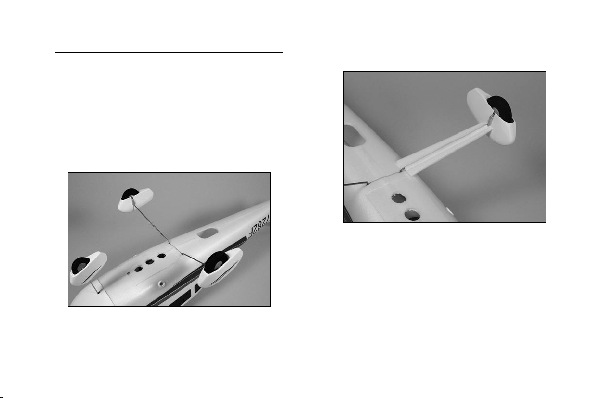
3. Slide the stabilizer into position. Use a ruler to
check that the distance between the stabilizer tips
and wing tips are the same. Adjust as necessary.
4. Check that the stabilizer is parallel to the wing.
Sand the fuselage lightly to make any corrections.
24
Page 25

5. Once the stabilizer has been aligned, use
foam-compatible CA to glue the stabilizer to the
fuselage.
6. Use foam-compatible CA to glue the tail cone
onto the fuselage.
7. Slide the elevator pushrod wire through the
micro control connector. Attach the "Z" bend
to the elevator control horn. With the radio on
and elevator trim centered, physically center the
elevator. Tighten the screw in the connector to
secure the pushrod wire.
25
Page 26

Battery Installation
Required Parts
Assembled airframe Battery
Battery door
Required Tools and Adhesives
Foam-compatible CA
1. With the aircraft fully assembled, install the
battery into the battery compartment. Secure the
battery using the hook and loop material.
2. Install the battery door to the bottom of the
fuselage. The magnet will hold the battery hatch
in place.
26
Page 27

Control Throws
1. Turn on the transmitter and receiver of your
Cessna 182. Check the movement of the rudder
using the transmitter. When the stick is moved
right, the rudder should also move right. Reverse
the direction of the servo at the transmitter if
necessary.
2. Check the movement of the elevator with the
radio system. Moving the elevator stick down will
make the airplane elevator move up.
3. Use a ruler to adjust the throw of the elevator,
ailerons and rudder. Adjust the position of
the pushrod at the control horn to achieve the
following measurements when moving the sticks to
their endpoints.
Ailerons:
1/4" (6mm) Up/Down
Elevator:
5/8" (16mm) Up/Down
Rudder:
1/2" (12mm) Right/Left
These are general guidelines measured from our own flight
tests. You can experiment with higher rates to match your
preferred style of flying.
27
Page 28

Center of Gravity
Range Testing the Radio
Caution: Do not inadvertently skip this step!
The recommended Center of Gravity (CG) location for the
Cessna 182 is 1
upper wing against the fuselage.
1
/
" (38mm) behind the leading edge of the
2
1. Before each flying session, be sure to range
check your radio. This is accomplished by
turning on your transmitter with the antenna
collapsed. Turn on the receiver in your airplane.
With your airplane on the ground and the
engine running, you should be able to walk 30
paces (approximately 100 feet) away from your
airplane and still have complete control of all
functions. If not, don’t attempt to fly! Have your
radio equipment checked out by the manufacturer.
2. Double-check that all controls (aileron, elevator,
rudder and throttle) move in the correct direction.
3. Be sure that your transmitter batteries are fully
charged, per the instructions included with your
radio.
28
Page 29

Preflight
Check Your Radio
Before going to the field, be sure that your batteries
are fully charged, per the instructions included with your
radio. Charge both the transmitter and receiver pack for
your airplane. Use the recommended charger supplied
with your particular radio system, following the instructions
provided with the radio. In most cases the radio should be
charged the night before going out flying.
Before each flying session, be sure to range
check your radio. See your radio manual for the
recommended range and instructions for your radio
system. Each radio manufacturer specifies different
procedures for their radio systems. Next, start the motor.
With the model securely anchored, check the range
again. The range test should not be significantly affected.
If it is, don’t attempt to fly! Have your radio equipment
checked out by the manufacturer.
Note: Keep loose items that can get entangled
in the propeller away from the prop. These
include loose clothing, or other objects such as
pencils and screwdrivers. Especially keep your
hands away from the propeller.
Double-check that all controls (aileron, elevator, rudder
and throttle) move in the correct direction.
Check the radio installation and make sure all the
control surfaces are moving correctly (i.e. the correct
direction and with the recommended throws). Test run the
motor and make sure it transitions smoothly from off to
full throttle and back. Also ensure the engine is installed
according to the manufacturer’s instructions, and it will
operate consistently.
Check all the control horns, servo horns, and clevises
to make sure they are secure and in good condition.
Replace any items that would be considered questionable.
Failure of any of these components in flight would mean
the loss of your aircraft.
29
Page 30

2005 Official AMA
National Model Aircraft Safety Code
GENERAL
1) I will not fly my model aircraft in sanctioned events,
air shows or model flying demonstrations until it
has been proven to be airworthy by having been
previously, successfully flight tested.
2) I will not fly my model higher than approximately
400 feet within 3 miles of an airport without notifying
the airport operator. I will give right-of-way and avoid
flying in the proximity of full-scale aircraft. Where
necessary, an observer shall be utilized to supervise
flying to avoid having models fly in the proximity of
full-scale aircraft.
3) Where established, I will abide by the safety rules
for the flying site I use, and I will not willfully or
deliberately fly my models in a careless, reckless and/
or dangerous manner.
4) The maximum takeoff weight of a model is 55
pounds, except models flown under Experimental
Aircraft rules.
5) I will not fly my model unless it is identified with
my name and address or AMA number on or in the
model. (This does not apply to models while being
flown indoors.)
6) I will not operate models with metal-bladed
propellers or with gaseous boosts, in which gases
other than air enter their internal combustion
engine(s); nor will I operate models with extremely
hazardous fuels such as those containing
tetranitromethane or hydrazine.
RADIO CONTROL
1) I will have completed a successful radio equipment
ground range check before the first flight of a new or
repaired model.
2) I will not fly my model aircraft in the presence
of spectators until I become a qualified flier, unless
assisted by an experienced helper.
30
Page 31

3) At all flying sites a straight or curved line(s) must
be established in front of which all flying takes place
with the other side for spectators. Only personnel
involved with flying the aircraft are allowed at or in
front of the flight line. Intentional flying behind the
flight line is prohibited.
4) I will operate my model using only radio control
frequencies currently allowed by the Federal
Communications Commission. (Only properly licensed
Amateurs are authorized to operate equipment on
Amateur Band frequencies.)
5) Flying sites separated by three miles or more
are considered safe from site-to-site interference,
even when both sites use the same frequencies. Any
circumstances under three miles separation require a
frequency management arrangement, which may be
either an allocation of specific frequencies for each site
or testing to determine that freedom from interference
exists. Allocation plans or interference test reports
shall be signed by the parties involved and provided
to AMA Headquarters. Documents of agreement and
reports may exist between (1) two or more AMA
Chartered Clubs, (2) AMA clubs and individual AMA
members not associated with AMA Clubs, or (3) two or
more individual AMA members.
6) For Combat, distance between combat engagement
line and spectator line will be 500 feet per cubic inch
of engine displacement. (Example: .40 engine = 200
feet.); electric motors will be based on equivalent
combustion engine size. Additional safety requirements
will be per the RC Combat section of the current
Competition Regulations.
7) At air shows or model flying demonstrations, a
single straight line must be established, one side of
which is for flying, with the other side for spectators.
8) With the exception of events flown under AMA
Competition rules, after launch, except for pilots or
helpers being used, no powered model may be flown
closer than 25 feet to any person.
9) Under no circumstances may a pilot or other person
touch a powered model in flight.
31
Page 32

7994
© 2005 Horizon Hobby, Inc.
4105 Fieldstone Road
Champaign, Illinois 61822
(877) 504-0233
horizonhobby.com
E-fliteRC.com
 Loading...