

Page 1
ValveMate
™
7040 Controller
Operating Manual
Electronic pdf files of EFD®manuals are also available at www.efd-inc.com/manuals.html
USA: 800-556-3484 or +1-401-434-1680
Europe: 0800 585733 or +44 (0) 1582 666334
Asia: +86 (21) 5854 2345
technical@efd-inc.com www.efd-inc.com
VALVEMATE
7040
A NORDSON COMPANY
Page 2

EFD ONE YEAR LIMITED WARRANTY
All components of the EFD ValveMate 7040 are warranted for one year from
date of purchase to be free from defects in material and workmanship (but not
against damage caused by misuse, abrasion, corrosion, negligence, accident,
faulty installation or by dispensing material incompatible with equipment) when
the equipment is installed and operated in accordance with factory recommendations and instructions. EFD will repair or replace free of charge any part
of the equipment thus found to be defective, on authorized return of the part
prepaid to our factory during the warranty period.
In no event shall any liability or obligation of EFD arising from this warranty
exceed the purchase price of the equipment. This warranty is valid only when
oil-free, clean, dry, filtered air is used.
EFD makes no warranty of merchantability or fitness for a particular purpose.
In no event shall EFD be liable for incidental or consequential damages.
Page 3

Warranty ....................................................inside cover
Introduction and Specifications ..................................2
Operating Features ......................................................3
Typical Setup................................................................4
Setup ........................................................................5-6
Adjusting the Spray......................................................7
Programming Nozzle Air Delay ....................................8
Schematic and Replacement Parts ............................9
Troubleshooting Guide ..............................................10
Input / Output Connections..................................11-12
Connecting More than One 7040 Controller..............13
Contents
Page 4

2 / Introduction and Specifications
The ValveMate 7040 provides easy adjustment of valve output for maximum
end-user convenience and efficiency. Designed for use with the 781S
Series spray valves, the ValveMate 7040 features an adjustable nozzle airflow regulator and a microprocessor-based timed air-pressure output for
controlling valve ON time. The ValveMate 7040 is simple to use and will
operate many millions of cycles without maintenance.
Introduction
Note: Specifications and technical
details are subject to engineering
changes without prior notification.
Size: 19 cm W x 14 cm D x 7 cm H (7.5”W x 5.6”D x 2.7” H)
Weight: 1.4 kg (3.1 lb)
Cabinet: Aluminum
Input Voltage: Selectable 100/120/220 VAC
Internal Voltage: 24 VDC
Feedback Circuits: 5 to 24 VDC NC solid-state switch 250mA maximum
Initiate Circuit: 5 to 24 VDC signal or contact closure
Air Input: 70 psi (4.8 bar)
Cycle Rate: Exceeds 600 per minute
Time Range: .001 to 99.9 seconds
Meets CSA and CE standards.
Specifications
The small size and adjustable mounting bracket allow for positioning of the
ValveMate close to the point of valve operation and provide convenient
access to setup and dispensing adjustment controls.
“On the fly” time adjustment allows adjustment of valve output while the
equipment is running. This feature eliminates the need to shut down parent
machinery to change or adjust dispense time settings.
Other features and explanations of controls are detailed in the diagrams on
pages 4 and 5.
Page 5
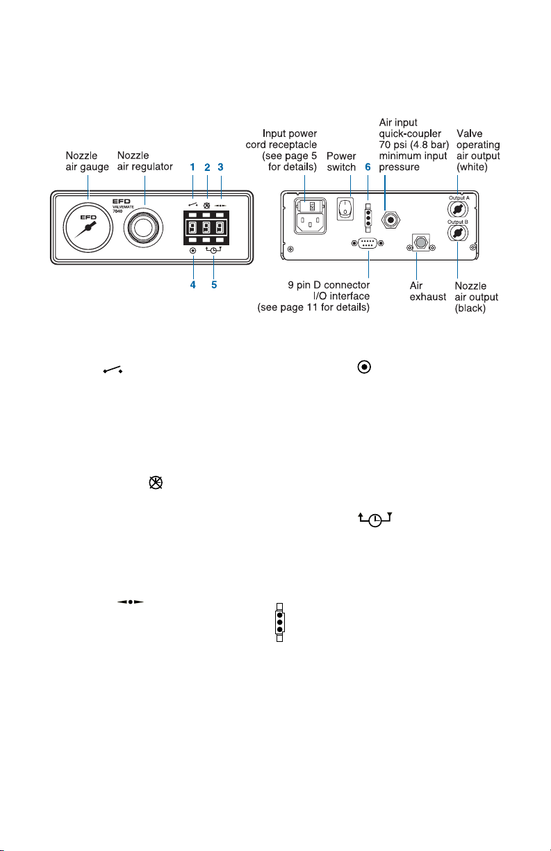
3 / Operating Features
1. Cycle
Press to initiate one complete
dispense cycle. Press again to
interrupt a timed cycle. Press
and hold while in the time override mode for continuous cycle.
Release to stop.
2. Time override
Press to override time control.
Display will show (---). While in this
mode, dispensing is manual using
the cycle button, voltage initiate
source or foot pedal (optional,
#2015A).
3. Decimal
Press to move decimal and change
time range maximums from .999
to 9.99 or 99.9. Decimal does not
appear in the display while in the
.999 second range.
Operating Features
4. Program
Press to clear display to zeros.
Display flashes bright/dim while in
program mode.
Press cycle button and hold until
proper amount is sprayed. Total
spray time will be displayed. Press
program button again to lock in
spray time.
5. Time set
Press to change time setting up or
down. Press and release to advance
one digit at a time, or press and
hold to scroll quickly.
6. Foot pedal connector
If using the optional foot pedal, press
the pedal momentarily to initiate the
controller. To interrupt a timed dispense cycle, press the pedal again.
Page 6

4 / Typical Setup
Caution: Always depressurize the reservoir
before opening. To do this, slide the shutoff valve
on the air line away from the reservoir. If using
an EFD tank, open the pressure relief valve as
well. Before opening the reservoir, check the
pressure gauge to verify that pressure is zero (0).
On all EFD cartridge reservoirs, the unique
threaded design provides fail-safe air pressure
release during cap removal.
Typical Setup
Five micron filter regulator
Plant air
70 psi (4.8 bar)
minimum
White quick-connect
Air tee #1116
To exhaust
To pressurize
Shut-off valve
Flexible air line
#2310S
Note: Use only oil-free,
clean, dry, filtered air
Controller
VALVEMATE
7040
ValveMate
7040 Controller
Material
Constant air
Pulsed air for valve operation
Pulsed nozzle air
Black quick-connect
Fluid feed hose
Pressurized
reservoir with
5
0
LVL P
spray valve
20
air regulator
Fluid inlet
fitting
#7543BP
for 1/4" OD tube
#7610BP
for 3/8" OD tube
Page 7

5 / Setup
VALVEMATE
70
40
➀ Mounting
Use the universal mounting bracket
(included) to mount the controller
either over or under the cabinet. The
bracket allows the controller to pivot
30º from a horizontal position. For
panel mounting, a panel mount
bracket kit is available (#7000PMK).
➁ Input Power
1. View cartridge window in power
cord receptacle to ensure that the
voltage is set properly. Selections
are 100, 120 or 220 VAC.
2. If it does not match, remove the
fuse cartridge. Then remove the
fuse holder from the cartridge,
rotate the holder and position the
correct voltage to show through
the cartridge window.
Reassemble in reverse order.
3. Connect the power cord.
Setup
Voltage value
Spare fuse
Cartridge window
(check voltage indicated)
➀
2
2
0
120
0
0
1
Page 8

➂
Initiate Connection
The 7040 can be operated by
applying a 5 to 24 VDC pulse to
terminal pins 1 and 2, or providing
contact closure across pins 5 and
7. Alternatively, a foot pedal may
be ordered (#2015A) and plugged
into the connector located on the
rear panel.
➃
Air Input Connection
1. Connect the controller to plant air
by first installing the five micron
filter regulator (#2000F755) to
the plant air supply.
2. Install the air tee with barb fitting (#1116 supplied with EFD
tank reservoirs) in the output of
the filter regulator, and install the
black hose with coupling to the
barb fitting. The quick-connect
on the air tee is used to provide
air pressure to the air pressure
regulator on EFD tank reservoirs. This connection will be
made during valve installation.
3. Remove the cap plug from the air
input of the controller and attach
the input air hose coupling onto
the controller air-input fitting.
4. Set the pressure at the filter
regulator to 70 psi (4.8 bar).
➄ Control Air Output
The 781S is equipped with nozzle
and control air hoses with male
quick-connects that plug into the
ValveMate7040.
a) Plug the control air hose
labeled “A” into output “A”
(white) of the 7040.
b) Plug the nozzle air hose
labeled “B” into output “B”
(black).
➅ Power
1. Turn the power switch on.
2. Press the time override button
to place the controller in manual
mode (---).
6 / Setup
➂
➅
➄
a
➄
b
➃
Setup
120
Output A
Output B
Page 9

7 / Adjusting the Spray
Adjusting the Spray
1. Turn the nozzle air pressure on the
controller to zero. Using the needle stroke control knob ➀ on the
781S valve, set the fluid flow rate
to one or two drops per second.
Check flow rate by actuating the
controller in the time override
mode. Make valve stroke adjustments when the controller is off.
2. Set the nozzle air pressure on the
controller to 10 psi (0.7 bar) and
actuate the controller. The valve
will produce a fine spray.
3. To change fluid flow, use the
needle stroke control knob ➀,
and/or tank air pressure.
Note: Avoid tight stroke settings with high
tank pressure.
4. To change nozzle air, use the nozzle
air pressure regulator ➁. Higher
pressures will provide finer spray.
To Make Timed Deposits
1. Return to the time control by pressing the time override button ➂. The
display should show the time setting.
2. Adjust the deposit time to 0.5 seconds by using the time set ➃ and
decimal ➄ buttons.
3. Press the cycle button ➅. The controller will open the valve for 0.5 seconds. Adjust time and test deposits
until desired output is obtained.
➀
VALVEMATE
7040
➁
➂➃➄
➅
Note: Optimal results will be obtained
with the proper combination of time
setting, needle stroke control knob,
and reservoir and nozzle air pressure.
Page 10

8 / Programming Nozzle Air Delay
Nozzle air delay is the time the nozzle air continues to
spray after the fluid is turned off. When spot marking
with low viscosity fluids, the delay can be reduced to
prevent blowing out the center of the mark. The delay
can be increased with high viscosity fluids and greases
to provide a spreading out effect.
1. Turn the power switch off.
2. Press and hold the time override button while
turning power switch on.
3. The display will read “SEL” (select). Release the
time override button.
4. Press either the up or down time set buttons once
and release. The current nozzle air-delay setting will
be displayed. (The delay is preset to 0.24 seconds
for all new controllers.)
5. Press the up or down time set button again to program the new nozzle air delay. (Available range is
0.00 to 2.50 seconds.)
6. To exit the nozzle air-delay program mode, momentarily press the time override button. The spray time
setting will be displayed.
Note: The controller will not operate while in the nozzle air
delay program mode.
Programming Nozzle Air Delay
Page 11

9 / Schematic and Replacement Parts List
Schematic and Replacement Parts List
1. 2-2002-7040 Regulator assembly
0 to 30 psi, 0 to 2.07 bar
2. 2-2003-7040A Control solenoid assembly
3. 2-2003-7040B Nozzle air solenoid assembly
4. 2-2006DB-VC Display PCB assembly
5. 2-2006PS-VC Power supply PCB assembly
6. 2-2017-1500 Foot pedal
receptacle assembly
7. 2001A Gauge 0 to 30 psi,
0 to 2.07 bar
8. 2004B Female quick-connect – black
(hidden from view
- below item #9)
9. 2004B-W Female quick-connect – white
10. 2024-160 1/4” OD x .160” ID tubing
11. 2081A Air input quick-connect
12. 2085 1/8 NPT x 1/4 barb – low profile
13. 2086 1/8 NPT x 1/4 barb 90° – brass
14. 2087 1/8 NPT x 1/4 barb elbow – brass
15. 2088 Fitting
1/8 NPT x 1/4 barb – brass
16. 7108 Exhaust muffler
17. 7109 Power switch
18. 7111 Fuse – .125A
19. 7143-01 Output circuit fuse
16
9
14
3
11
2
12
14
18
6
17
19
5
10
15
7
14
13
4
1
Input Air
Regulated Air
Page 12

Timer seems inoperative.
Troubleshooting Guide
End-of-cycle feedback circuit
is not functioning
No power
Valve does not spray below
.015 second time setting
If trouble cannot be corrected, or if you need further assistance,
please call us
.
In the US, call 800-556-3484. In the UK, phone 0800 585733.
In Asia, +86 (21) 5854 2345.
Trouble Possible cause and correction
Be sure that there is power at the wall
receptacle. Check the input power fuse.
If the fuse has blown, check the voltage
value in the fuse cartridge window. Be
sure that it matches the input voltage.
Ensure that the external voltage to the
circuit is between 5 and 24 VDC and that
the load does not exceed 250mA. If the
circuit has been overloaded, the fuse may
have blown. Replace fuse, if necessary.
Response delay in pneumatic circuit does
not allow the valve to open when time is
at or below 0.015 seconds. Increase time.
Valve operating pressure lower than 60 psi
(4.1 bar) can cause inconsistent output.
Make sure pressure is set at 70 psi (4.8 bar).
Check controller and reservoir air pressure readings to be sure air pressure is
not varying.
Air bubbles in the material can cause
inconsistency. For best results, remove all
air bubbles.
Check to be sure time override mode is off.
Inconsistent deposits
10 / Troubleshooting Guide
Page 13

11 / Input / Output Connections
Note: 9-pin male connector assembly is
included (replacement part # 7154).
]
]
5-24 VDC
250mA Max
5-24 VDC
Pin Function
1. Initiate +
2. Initiate -
3. Output +
4. Output -
5. Contact Closure
6. Chassis Ground
7. Contact Closure
8. Not Used
9. Not Used
I/O Connection
The 9-pin D connector
and internal circuitry provide external initiate and
end-of-cycle feedback
signal. The pin connections are shown below.
Input/Output Connections
1. Voltage Initiate Circuit
The controller may be initiated with
a 5 to 24 VDC signal across pins
1 and 2. The signal can be momentary (no less than 0.02 seconds) or
maintained. A new cycle will begin
once power is removed and then
applied again.
2. End-of-Cycle Feedback Circuit
Upon completion of a dispense
cycle, an open collector circuit
closes and remains closed until the
next dispense cycle. This circuit
can be utilized to signal back to a
host computer, start another device
in sequence or other operations
that need to be tied into completion of the dispense cycle.
Upon closure, power from an external 5 to 24 VDC source is allowed
to pass through the circuit to operate a load. The load illustrated is a
relay, but this could be any device
that will operate within the 5 to 24
volt range. Power consumption of
the load must not exceed 250mA.
3. Mechanical Contact Initiate
The controller can be initiated via
the closure of mechanical contacts such as a relay or switch
using pins 5 and 7. Closure of
the contacts can be momentary
(no less than 0.02 seconds) or
maintained. A new cycle will
begin once the contacts are
opened and then closed again.
Note: For applications using more than
one 7040, see page 15 for connection
instructions.
6789
12345
Page 14

Micro-
controller
Opto
coupler
Fuse
Voltage Initiate Circuit
5 to 24 VDC power source
power consumption
2.2mA at 5 VDC
15.0mA at 24 VDC
End-of-Cycle
Feedback Circuit
5 to 24 VDC power
source maximum
load 250mA
1
00/120/220 VAC
50/60 Hz 14/12 VA
+ 5 VDC
Solenoid 1
7815
control
Protector
Solenoid 2
atomizer
control
Power
supply
Nonvolatile
memory
Programmable
display
Opto
coupler
+ 24 VDC
Mechanical Contact Initiate
Mechanical contact power
consumption contact load
= 5.5 VDC / 100uA
Foot Pedal
+
+
_
_
2
3
4
5
7
1
A relay is
illustrated
as one example
for utilizing the
feedback circuit.
NOTE: DO NOT APPLY
VOLTAGE across pins
5 and 7.
12 / Input / Output Connections
Input/Output Connections
Page 15

13 / Connecting More Than One 7040 Controller
Connecting more than one 7040 Controller
2. Series circuit for End-of-Cycle Feedback
feature. A relay is illustrated as one
example for utilizing the feedback circuit.
1. Parallel circuit diagram for Voltage Initiate.
1. Voltage Initiate Circuit
To start the dispense cycle for multiple 7040 controllers at the same time,
connect the voltage initiate circuit in
parallel as illustrated.
Note: The amperage consumption for the
voltage initiate circuit will increase
with each controller that is connected.
The initiate power supply should be
sized accordingly.
2. End-of-Cycle Feedback Circuit
This circuit will ensure that the endof-cycle signal will come from the last
7040 to complete a dispense cycle.
Connect in series as illustrated.
Note: There will be a maximum voltage
drop of 2.0 VDC through the feedback circuit with each 7040 that is
added to the series. The input power
should be adjusted for this drop to
ensure that the required voltage is
available to operate the load.
Maximum input voltage to terminals
3 and 4 must not exceed 30.0 VDC.
12345
6789
12345
6789
12345
6789
5-24 VDC
-
_
+
Source
6789
6789
6789
+
12345
12345
12345
Page 16

For EFD sales and service in over 30 countries,
contact EFD or go to www.efd-inc.com/contact
EFD, Inc.
East Providence, RI USA
800-556-3484; +1-401-434-1680 (outside the USA)
info@efd-inc.com www.efd-inc.com
EFD International Inc.
Dunstable, Bedfordshire, UK
0800 585733 or +44 (0) 1582 666334
Ireland 00800 8272 9444
europe@efd-inc.com www.efd-inc.com
EFD, Inc., Asia
China: +86 (21) 5854 2345
china@efd-inc.com www.efd-inc.com/cn
Singapore: +65 6896 9630 sin-mal@efd-inc.com
©2006 Nordson Corporation 7040-MAN-01 v062606
®
A NORDSON COMPANY
This equipment is regulated by the European Union under WEEE
Directive (2002/96/EC). See www.efd-inc.com for information about
how to properly dispose of this equipment.
 Loading...