

Page 1
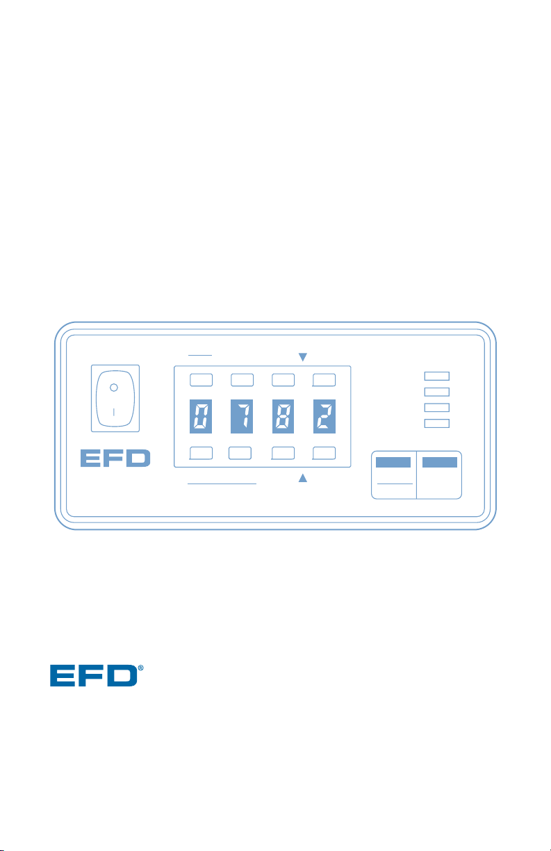
ValveMate
™
7000 Controller
Operating Manual
POWER
RUN
SETUP
CYCLE
Test
Clear
Purge
Run
Setup Program
Fast Slow
Time Set
Steady
Fast Slow
Time Set
STOP
Pressure
Time
®
A NORDSON COMPANY
VALVEMATE
7000
Electronic pdf files of EFD®manuals are also available at www.efd-inc.com/manuals.html
USA: 800-556-3484 or +1-401-434-1680
Europe: 0800 585733 or +44 (0) 1582 666334
Asia: +86 (21) 5854 2345
technical@efd-inc.com www.efd-inc.com
A NORDSON COMPANY
Page 2

EFD ONE YEAR LIMITED WARRANTY
All components of the EFD ValveMate 7000 are warranted for one year from
date of purchase to be free from defects in material and workmanship (but not
against damage caused by misuse, abrasion, corrosion, negligence, accident,
faulty installation or by dispensing material incompatible with equipment) when
the equipment is installed and operated in accordance with factory recommendations and instructions. EFD will repair or replace free of charge any part
of the equipment thus found to be defective, on authorized return of the part
prepaid to our factory during the warranty period.
In no event shall any liability or obligation of EFD arising from this warranty
exceed the purchase price of the equipment. This warranty is valid only when
oil-free, clean, dry, filtered air is used.
EFD makes no warranty of merchantability or fitness for a particular purpose.
In no event shall EFD be liable for incidental or consequential damages.
Page 3

Contents
Warranty ....................................................inside cover
Introduction..................................................................2
Specifications ..............................................................3
Features and Controls ..............................................4-5
Indicator Lamps .......................................................... 6
Typical Setup................................................................7
Setup ......................................................................8-10
Installing the Valve ....................................................11
Schematic and Replacement Parts List ....................12
Troubleshooting..........................................................13
Input/Output Connection Instructions..................14-15
Connecting More than One 7000 ........................16-17
Page 4

IMPORTANT: The primary
control of deposit size is the
valve open time. The ValveMate
7000 provides easy access
and “on the fly” adjustment
of valve open time.
2 / Introduction
Introduction
The ValveMate 7000 is an EFD dispense
valve controller, incorporating programmable
dispense time, digital time and air pressure
readout, microprocessor interface, small size
and universal mounting.
Other features include:
• Push-button time setting input or onetouch time programming.
• Floating decimal, providing dispense time
ranges of 0.001 to 9.999 and 00.01 to
99.99 seconds.
• Bright red LED that displays both time
setting and dispensing pressure in psi or
bar scale.
• Push-button purge feature.
• Low air-pressure alarm and End-of-Cycle
feedback signals.
The ValveMate 7000 has been designed
with the machine builder and operator in
mind. The objectives are to bring dispensing control close to the point of application,
and to provide the features necessary to
make setup and operation as easy and
precise as possible.
The ValveMate is easy to operate. Once
you have reviewed the features, you will
understand the benefits and the ease of
control the ValveMate provides.
As with all EFD products, the ValveMate has
been produced to exacting specifications
and thoroughly tested prior to shipment.
To obtain maximum performance from this
equipment, please read the instructions
carefully.
Page 5
Note: Specifications and technical
details are subject to engineering
changes without prior notification.
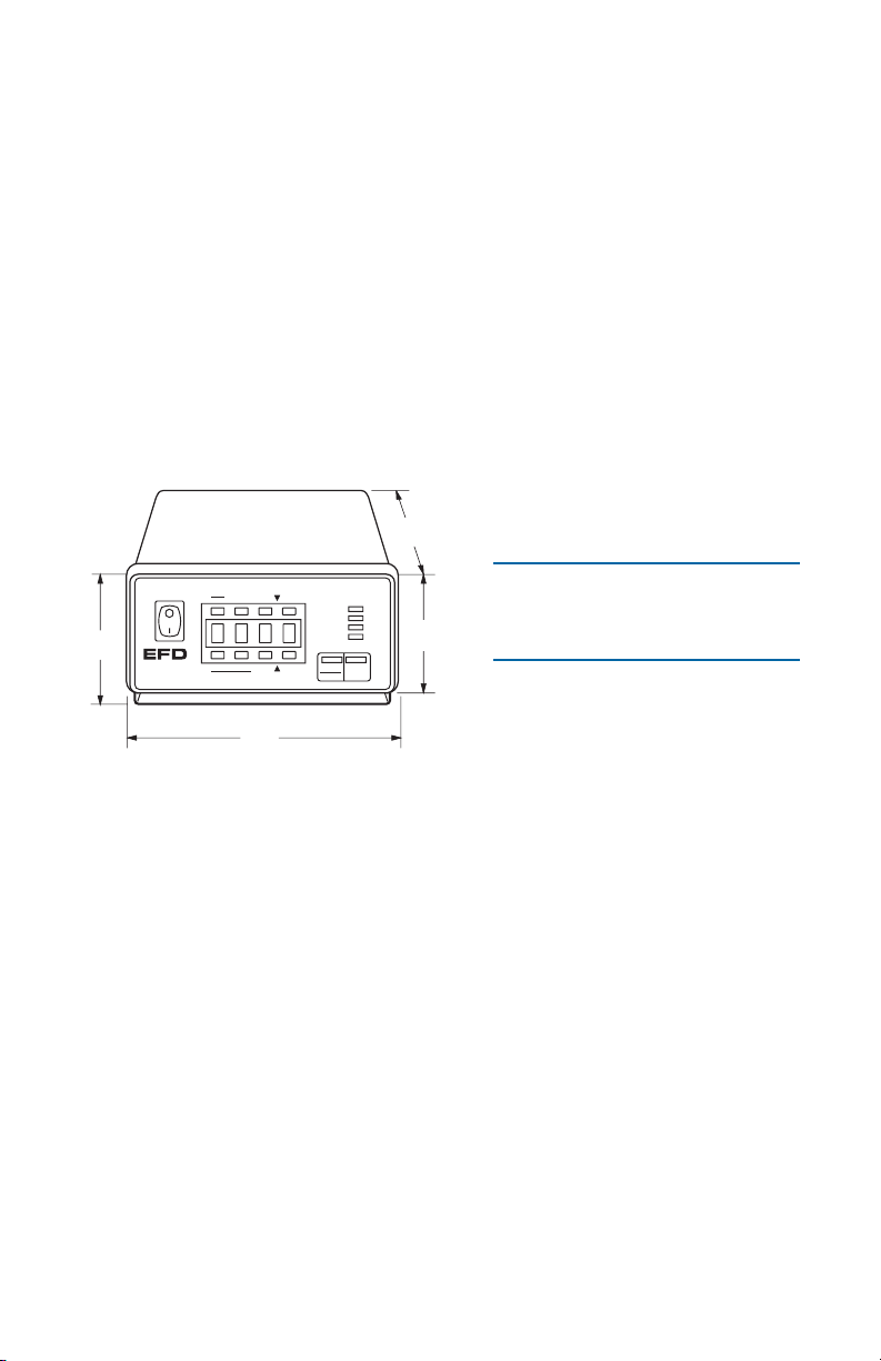
Size: 14 cm W x 14 cm D x 6 cm H (5.5”W x 5.6” D x 2.5” H)
Weight: 1.0 kg (2.3 lb)
Cabinet: Aluminum
Input Voltage: Selectable 100/120/220 VAC 50/60 Hz 10/9VA
Internal Voltage: 12 VDC
Feedback Circuits: 5 to 24 VDC NC solid-state switch 250mA maximum
Initiate Circuit: 5 to 24 VDC signal or foot pedal
Air Input: 70 psi (4.8 bar)
Air Consumption: Approximately 1.5 SCFM at 400 cycles per minute
Cycle Rate: Exceeds 600 per minute
Time Range: Programmable 0.001 to 9.999, or 00.01 to 99.99 seconds
Specifications
The small size and adjustable mounting bracket allow for positioning of the
ValveMate close to the point of valve operation and provide convenient
access to setup and dispensing adjustment controls.
Digital readout is shown for both dispensing time and air pressure.
“On the fly” time adjustment allows adjustment of valve output while the
equipment is running. This feature eliminates the need to shut down parent
machinery to change or adjust dispense time settings.
Other features and explanations of controls are detailed in the diagrams on
pages 4 and 5.
3 / Specifications
Slow
14 cm
(5.5")
14.2 cm
(5.6")
6.4 cm
(2.5")
8.6 cm
(3.4")
RUN
POWER
Run
Setup
Steady
Test
Purge Fast
FastClear
Slow
Program Time Set
Time Set
STOP
SETUP
CYCLE
Pressure
Time
®
A NORDSON COMPANY
VALVEMATE
7000
Meets CSA and CE standards.
Page 6
1. Digital time and air pressure LED display
Programmable floating decimal provides time
range readout from 0.001 to 99.99 seconds.
Pressure readout can be programmed to read
either in psi or bar. (Details on page 10.)
2. RUN / SETUP
Press to change the mode of operation
between RUN and SETUP.
The SETUP mode provides access to the
MEMORY, CLEAR, TEST and TIME SET
functions. While in the SETUP mode, time
values can be changed.
The RUN mode locks in the time displayed
and locks out access to the CLEAR and TIME
SET functions.
3. STEADY / TEST
In the RUN mode, press this button to place
the ValveMate into the STEADY mode (no
timer) and display will show dashes (---).
Press again to return the ValveMate to the
timed mode.
In the SETUP mode, this button initiates the
ValveMate through one complete cycle. Use
to test dispensing before going into the RUN
mode.
4. CLEAR
In the RUN mode, the function is inoperative.
In the SETUP mode, press to clear time and
display to zero.
5. TIME SET ▼ (down)
Use to scroll time display down. Left button
scrolls fast. Right button scrolls slowly.
6. STOP
This button, when pressed, stops the 7000
immediately. Also, holding this button in while
turning the power switch on will deactivate or
reactivate the low air pressure alarm.
7. PRESSURE / TIME
In the RUN mode, press to change the display
from time to pressure. Press a second time to
change pressure back to time.
In the SETUP mode, press and hold for 3.0
seconds to toggle pressure display from psi to
bar. Press a second time for 3.0 seconds to
toggle pressure display back to psi.
8. TIME SET ▲ (up)
Use to scroll time display up. Left button
scrolls fast. Right button scrolls slowly.
9. PURGE / PROGRAM
The RUN mode opens the valve for as long as
the button is held in. Use for priming or purging
air from the system.
The SETUP mode opens the valve and sets
time for as long as the button is held in. Use
for setting deposit amount when a specific
time value is not known.
Features and Controls
4 / Features and Controls
POWER
RUN
SETUP
CYCLE
STOP
Clear
Purge
Run
Setup Program
Fast Slow
Time Set
Steady
Test
Pressure
Time
Fast Slow
Time Set
34 5
7
6
89
1
2
®
A NORDSON COMPANY
VALVEMATE
7000
Page 7

5 / Features and Controls
1. Power cord receptacle with voltage
selection and fuse cartridge
Three input voltages can be used. 100 VAC,
120 VAC and 220 VAC. To change input voltage, remove fuse cartridge and position the
selected voltage marked on the cartridge so
that it shows through the window. (Details
on page 8.)
2. Foot pedal receptacle
For optional foot pedal, order part #2015A.
3. Air input push-in style fitting
Main air input supply is installed here. Set air
pressure at 70 psi (4.8 bar). Lower than 60
psi (4.1 bar) will trigger insufficient air pressure alarm and shut down all functions.
4. Air output quick-connect
Install male connector from EFD valve air
input hose here. Push in and turn clockwise
to lock.
5. Input / Output terminal strip
For detail connection schematic and instructions for input or output features, see diagram
on page 15.
• The 7000 features a low pressure alarm
system. An output signal, in the form of a
solid-state switch, closes when pressure
drops below 60 psi (4.1 bar). This closure
can be used to operate an audible alarm,
shut-off switch or other device. Maximum
load is 250mA from 5 to 24 VDC. In
addition, when the air pressure is low,
the display will flash between “air” and
“pressure” indicating that pressure has
dropped below minimum. (See page 4
for instructions on deactivating or reactivating the alarm.)
• An End-of-Cycle signal, also in the form of
a solid-state switch, closes upon completion of the dispense cycle. Maximum load
is 250mA from 5 to 24 VDC source (not
included).
• The 7000 can be initiated using a 5 to 24
VDC signal.
• The 7000 can also be initiated with a
contact closure such as a mechanical
relay or optional foot pedal (order separately #2015A).
220
Air Output
Fuse T 125mA 250V
100/120/ 220VAC
50/60Hz 10/9VA
1. Initiate +
2. Initiate -
3. Output +
4. Output
1 2 4 3 5 6 7
8
7. Contact Closure
8. Contact Closure
250mA
5-24 VDC
5. Alarm +
5-24 VDC
5-24 VDC
250mA
6. Alarm -
Foot Pedal
Input
Exhaust
Air
1
2
5
34
Page 8

6 / Indicator Lamps
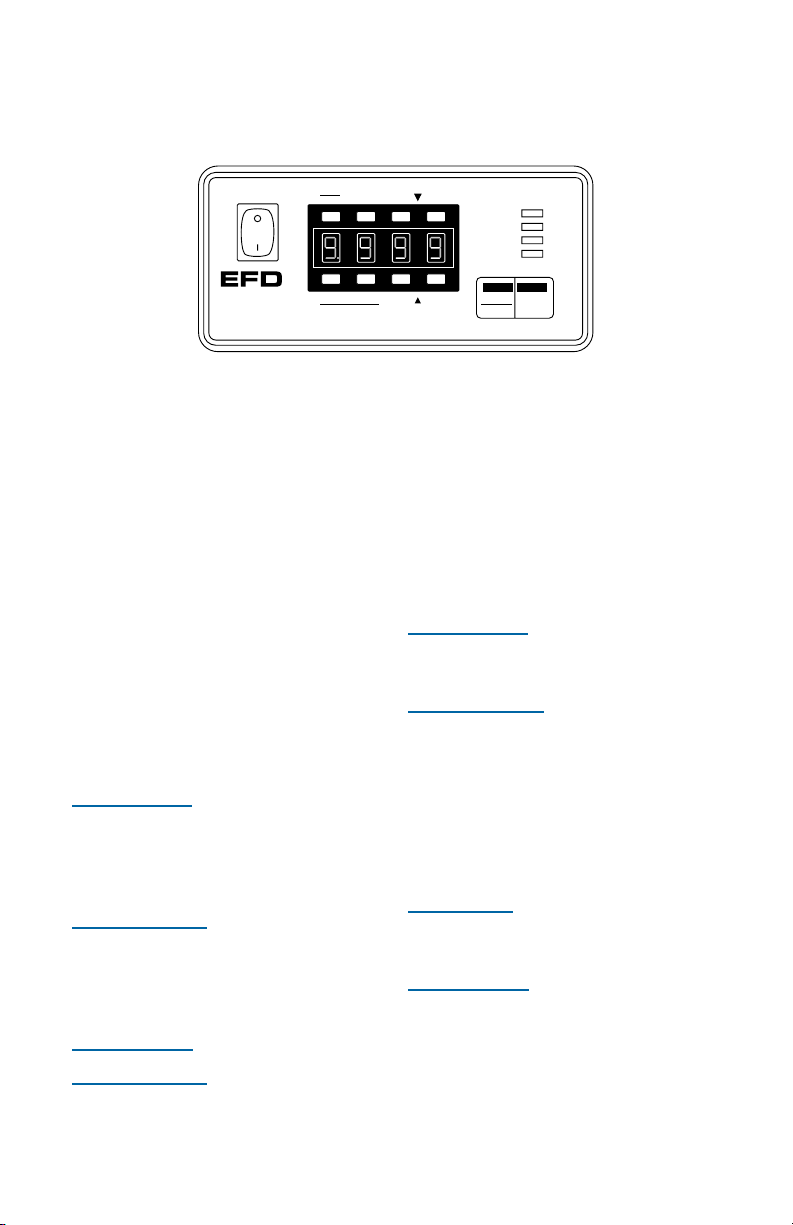
Indicator Lamps
In the upper right corner of the front panel are four indicator lamps. These lamps indicate the mode of operation.
POWER
--
Indicates that there is power to the ValveMate.
RUN--Indicates that the ValveMate is in the RUN mode
ready to be initiated through a dispense cycle.
SETUP--Indicates that the 7000 is in the SETUP mode.
Time settings can only be changed in this mode.
CYCLE
--
This lamp is on whenever the control solenoid is
open, causing the dispense valve to be open.
POWER
RUN
SETUP
CYCLE
STOP
Clear
Purge
Program
Run
Setup
Fast Slow
Time Set
Steady
Test
Pressure
Time
Time Set
Fast Slow
Page 9

Typical Setup
7 / Typical Setup
Five micron filter regulator
Shut-off valve
Page 10

➀
➁
Voltage value
Cartridge window
(check voltage indicated)
Spare fuse
➀ Mounting
Included with the 7000 is a universal mounting bracket. Mounting
hardware is installed into the four
10-32 mounting holes on the sides
of the cabinet. The bracket can
be mounted either over or under
the cabinet and will allow the 7000
to pivot up or down 30 degrees
from a horizontal position. The
bracket may be permanently
mounted, or attach the rubber feet
included and use the bracket as a
bench-top tilt stand. Four rubber
feet on the console are provided if
the bracket is not used.
For panel mounting, a panel
mount bracket kit is available
(order #7000PMK).
➁ Input Power
Check the input power cord receptacle fuse cartridge to ensure that
the voltage is set properly. The
cartridge may be set for input voltages of 100, 120, or 220 VAC.
To change voltage, remove the
fuse cartridge. Remove the fuse
holder from the cartridge, rotate
the holder and position the correct
voltage to show through the cartridge window. Replace the cartridge into the power cord receptacle and ensure that both sides
snap securely into position.
Install the power cord.
Setup
8 / Setup
2
2
0
120
1
0
0
Page 11

➂
➄
➃
9 / Setup
➂
Initiate Connection
The 7000 can be initiated through
a time cycle by the application of
5 to 24 VDC to terminals 1 and 2,
by closure of mechanical contacts
across terminals 7 and 8, or by
using an optional EFD foot pedal
(order #2015A), plugged into the
foot pedal receptacle. A connection schematic is detailed on page
15. Select one of these methods
and install now.
➃
Air Input Connection
Connect the ValveMate 7000 to
plant air by first installing the
EFD five-micron filter regulator
(#2000F755) to your air supply.
Install the air tee with barb fitting
(#1116) in the output of the filter
regulator.
10 feet of 1/4” OD air line is supplied.
Using the barb fitting supplied,
connect one end to the #1116 air
tee. Connect the other end of the
air line by pushing it firmly into the
air input connector on the ValveMate
7000 until it bottoms out. Be sure
that the line is inserted all the way
into the fitting.
Set the pressure at the #2000F755
filter regulator to 70 psi (4.8 bar).
The quick-connect on the air tee is
used to provide air pressure to the
air pressure regulator on EFD fluid
reservoirs. This connection will be
made at a later step in the setup.
➄ Control Air Output
The dispense valve is connected to
this output quick-connect. All EFD
dispense valves are equipped with
the matching male connector.
Insert and twist to lock. At this
point, however, do not attach the
dispense valve.
Please continue to next page.
220
Air Output
Fuse T 125mA 250V
100/120/220VAC
50/60Hz 10/9VA
1. Initiate +
2. Initiate -
3. Output +
4. Output
1 2 4 3 5 6 7
8
7. Contact Closure
8. Contact Closure
250mA
5-24 VDC
5. Alarm +
5-24 VDC
5-24 VDC
250mA
6. Alarm -
Foot Pedal
Input
Exhaust
Air
Page 12

10 / Setup
➅
➆➇
➅
Turn the Power Switch On.
➆
Setting the Decimal
The 7000 is shipped with the decimal set at the 99.99 second range.
If the 9.999 second range is desired,
change as follows:
To place the display into the time
position, press the
PRESSURE / TIME
button. This will toggle the display
from pressure to time readout.
To move the decimal, press the
STOP
button and hold it for 3.0 seconds.
The decimal point will switch to
0.000. To change back to 00.00,
press and hold
STOP
again.
➇
Setting the Pressure Readout
The 7000 is shipped with pressure
display programmed in psi.
If bar is desired, change as follows:
Press
RUN / SETUP
and place the
7000 into the
SETUP
mode. Press
and hold the
PRESSURE / TIME
button for 3.0 seconds. The display
will change from psi to bar. To
change back to psi, press and hold
PRESSURE / TIME
for approximately
3.0 seconds.
POWER
RUN
SETUP
CYCLE
STOP
Test
Clear
Purge
Run
Setup Program
Fast Slow
Time Set
Steady
Pressure
Time
Fast Slow
Time Set
®
A NORDSON COMPANY
VALVEMATE
7000
Note:
Changing the decimal place will
change the current time setting by a factor
of 10X. (Example - time setting of 5.350
becomes 53.50.)
Page 13

11 / Installing the Valve
Installing the Valve
All EFD dispense valves are supplied with a complete instruction
manual. If you have not yet read
the manual, do this now. The manual will explain the operation of the
valve and also how to set up the
valve with the fluid reservoir.
FINAL SETUP CHECKLIST
• Fuse cartridge voltage has
been checked or adjusted.
• Either voltage or mechanical
contact initiate is connected.
• Air pressure of 70 psi (4.8 bar)
is connected to the air input fitting.
• Power on.
• Decimal place is set.
• Pressure value is set for psi
or bar.
Once you have read the operating
manual for the valve that you are
using, connected the valve to the fluid
reservoir and have the reservoir properly pressurized, you may begin the
following steps to install the valve:
1. Install the quick-connect from
the air line on the valve to the air
output on the back of the 7000.
Simply push in and twist to the
right to lock.
2. Pressure to the 7000 should be
set at 70 psi (4.8 bar).
Remember, pressure may be
checked by pressing the
PRES-
SURE / TIME
button.
3. Place a container under the outlet of the dispense valve.
4. Select and install a dispensing
tip on the valve output tip
adapter.
5. Place the 7000 into the
RUN
mode and press
PURGE / PRO-
GRAM
. Hold the button until liquid fills the lines and begins to
flow from the valve.
6. Continue to purge until the liquid
feed lines and valve are free of air.
7. Set up the deposit size using the
TIME SET
buttons illustrated on
page 4. Pressing the
TEST
button
in the
SETUP
mode will initiate one
dispense cycle.
Page 14

12 / Schematic and Replacement Parts List
Replacement Parts List
1. 7104A Display board
2. 7105A Power supply board
3. 7106D Fuse drawer
4. 7107A Air input hose fitting,
push-in style
5. 7108
* Exhaust muffler
6. 7109 Power switch
7. 7111 Fuse .125A
8. 7123 Transformer
9. 7131 Pressure sensor
10. 7143-01 Output circuit fuses
11. 2004B Female quick-connect, black
12. 2009-A24 Power cord*
13. 2024-160 1/4” OD x .160” ID tubing
14. 2085 1/8 NPT x 1/4 barb elbow,
low profile
15. 2086 1/8 NPT x 1/4 barb 90°, brass
16. 2087 1/8 NPT x 1/4 barb elbow, brass
17. 2-7125-7000 Solenoid
18. 2-2017-1500 Foot pedal receptacle assembly
19. 20000F755
* Five micron filter regulator
20. 2015A* Foot pedal assembly (optional)
* Not Shown
55
11
3
7
18
4
4
99
18
10
131313
13
17
14
16
6
2
8
15
1
Page 15

Timer is inoperative.
Troubleshooting Guide
Unit changes from
RUN
to
SETUP, SETUP
light is flashing,
and unit has to be reset.
13 / Troubleshooting
There is an “AIR”message.
No power.
If trouble cannot be corrected, or if you need further assistance,
please call
us
. In the US, call 800-556-3484. In the UK, phone 0800 585733.
In Asia, +86 (21) 5854 2345.
Trouble Possible cause and correction
The low level air alarm is active. Raise the
input pressure to 70 psi (4.8 bar) on the
display. Press
RUN / SETUP
button to reset.
Air pressure has momentarily dropped
below 60 psi (4.1 bar). Increase input air
pressure to 70 psi (4.8 bar). If already at
70 psi (4.8 bar), check to make sure that
other devices such as air cylinders are not
causing a pressure drop in the ValveMate
7000 input air line.
Check the input power fuse. If the fuse
has failed, check the voltage value in the
fuse cartridge window. Be sure that it
matches the input voltage.
Ensure that the external voltage to the
circuit is between 5 and 24 VDC and that
the load does not exceed 250mA.
If the circuit has been overloaded, the
fuse may be open. See internal diagram
on page 15 and replace fuse if necessary.
Response delay in pneumatic circuit does
not allow the valve to open when time is set
at or below 0.010 seconds. Increase time.
Check to make sure unit is not in
STEADY
mode. The timer is very reliable. Any failure
is total, so no inconsistency is possible.
End-of-Cycle Feedback
Circuit or low pressure alarm
is not functioning.
Does not dispense below
0.010 second time setting.
Page 16

1. Voltage Initiate Circuit
The ValveMate 7000 may be initiated with a 5 to 24 VDC
signal. The signal can be momentary (no less than 0.008
seconds) or maintained. A new cycle will begin once
power is removed and then applied again. Refer to the
schematic for proper installation.
2. End-of-Cycle Feedback Circuit
Upon completion of a dispense cycle, an open collector
circuit closes and remains closed until the next dispense
cycle. This circuit can be utilized to signal back to a
host computer, start another device in sequence or other
operations that need to be tied into the completion of
the dispense cycle.
Upon closure, power from an external source is allowed
to pass through the circuit to operate a 5 to 24 VDC load.
The load illustrated is a relay, but this could be any device
that will operate within the 5 to 24 volt range. Power
consumption of the load must not exceed 250mA.
3. Low Pressure Alarm Circuit
The ValveMate features a low pressure alarm output that
activates whenever pressure drops below the minimum
valve operating pressure of 60 psi (4.1 bar).
Function and circuitry is identical to the feedback circuit
described in #2.
See page 4 for deactivate/reactivate procedure.
4. Mechanical Contact Circuit
The ValveMate can be initiated via the closure of mechanical
contacts such as a relay or switch. Closure of the contacts
can be momentary (no less than 0.008 seconds) or
maintained. A new cycle will begin once the contacts
are opened and then closed again. Refer to the
schematic for proper installation.
Note: For applications using more than one 7000,
see pages 16 and 17 for connection instructions.
Input/Output Connections
14 / Input/Output Connections
Page 17

15 / Input/Output Connections
100/120/
220 VAC
50/60 Hz
10/9VA
Programmable
Display
Nonvolatile
Memory
Pressure
Sensor
Power
Supply
+5 VDC
+12 VDC
Micro-
controller
Solenoid
Valve
Opto
Coupler
Opto
Coupler
Opto
Coupler
Protector
Fuse
Fuse
1. Voltage
Initiate Circuit
+
5 to 24 VDC
Power Source
_
Power Consumption
1
2
3
4
5
6
Lamp
7
8
2.2mA at 5 VDC
15.0mA at 24 VDC
2. End-of-Cycle
Feedback Circuit
+
5 to 24 VDC
_
Power Source
Maximum Load
250mA
3. Low Pressure
+
Alarm Circuit
5 to 24 VDC
_
Power Source
Maximum Load
250mA
4. Mechanical
A relay and
a lamp are
illustrated as
examples for
utilizing the
feedback and
alarm circuits.
Contact Initiate
Mechanical Contact
Power Consumption
Contact Load =
5.5 VDC / 100uA
NOTE:
DO NOT APPLY VOLTAGE
Page 18

1. Parallel circuit diagram for Voltage
Initiate. The same diagram should be
used when connecting Low Pressure
Alarm terminals 5 & 6 or Mechanical
Contact Initiate terminals 7 & 8.
16 / Connecting More than One 7000
Connecting More than One 7000
Follow these instructions and diagrams
when the Voltage Initiate or End-ofCycle Feedback features are used in
a multiple 7000 installation.
1. Voltage Initiate Circuit
To start the dispense cycle for multiple 7000’s at the same time, connect
the Voltage Initiate Circuit, the Contact
Closure Initiate and the Low Pressure
Alarm Circuits in parallel as illustrated.
Note:
The amperage consumption for the
Voltage Initiate Circuit will increase with each
ValveMate 7000 that is connected. The initiate power supply should be sized accordingly.
Example: First 7000 consumes
15.0mA at 24 volts. Second one will
consume another 15.0mA; now total
is 30.0mA. Third one will consume
another 15.0 making the total 45.0mA
and so on.
Page 19

17 / Connecting More than One 7000
2. End-of-cycle Feedback Circuit
This circuit will ensure that the Endof-Cycle will come from the last 7000
to complete a dispense cycle. Connect
in series as illustrated.
Note:
There will be a maximum voltage drop
of 2.0 VDC through the Feedback Circuit with
each 7000 that is added to the series. The
input power should be adjusted for this drop
to ensure that the required voltage is available
to operate the load. Maximum input voltage
to terminals 3 & 4 must not exceed 30.0 VDC.
Example: The load to be operated
through the Feedback Circuit is 12
VDC. Four 7000’s are to be used.
4 X 2.0 = 8.0 VDC drop. Power
supply should provide (12.0 + 8.0)
or 20.0 VDC to ensure that 12.0 VDC
is available to run the load.
Stack mounting two or more ValveMate 7000’s.
Use the dimensions in the illustration to make up
mounting bracket from flat stock.
2. Series circuit for End-of-Cycle
Feedback feature. A relay is illus-
trated as one example for utilizing
the Feedback Circuit.
REMEMBER: Maximum current
through the Feedback Circuit must
not exceed 250mA.
28.7 mm (1.13”)
25.9 mm (1.02”)
69.9 mm
(2.75”)
5.2 mm (13/64”) hole size
Page 20

For EFD sales and service in over 30 countries,
contact EFD or go to www.efd-inc.com/contact
EFD, Inc.
East Providence, RI USA
800-556-3484; +1-401-434-1680 (outside the USA)
info@efd-inc.com www.efd-inc.com
EFD International Inc.
Dunstable, Bedfordshire, UK
0800 585733 or +44 (0) 1582 666334
Ireland 00800 8272 9444
europe@efd-inc.com www.efd-inc.com
EFD, Inc., Asia
China: +86 (21) 5854 2345
china@efd-inc.com www.efd-inc.com/cn
Singapore: +65 6896 9630 sin-mal@efd-inc.com
©2006 Nordson Corporation 7000-MAN-01 v062606
®
A NORDSON COMPANY
This equipment is regulated by the European Union under WEEE
Directive (2002/96/EC). See www.efd-inc.com for information about
how to properly dispose of this equipment.
 Loading...