


USER MANUAL
MANUAL DE INSTRUCCIONES NOTICE D'UTILISATION BEDIENUNGSANLEITUNG

Graphic Symbol Explanation
The lightning flash with arrowhead symbol, within an equilateral triangle, is intended to alert the user to the presence of uninsulated “dangerous voltage” within the product’s enclosure that may be of sufficient magnitude to constitute a risk of electric shock to persons.
The exclamation point within an equilateral triangle is intended to alert the user to the presence of important operating and maintenance (servicing) instructions in the literature accompanying the appliance.
The lightning flashes printed next to the OUTPUT terminals of the amplifier are intended to alert the user to the risk of hazardous energy. Output connectors that could pose a risk are marked with the lightning flash. Do not touch output terminals while amplifier power is on. Make all connections with amplifier turned off.
WARNING: To prevent fire or shock hazard, do not expose this equipment to rain or moisture.
IMPORTANT SAFETY INSTRUCTIONS
1.Read these instructions.
2.Keep these instructions.
3.Heed all warnings.
4.Follow all instructions.
5.Do not use this apparatus near water.
6.Clean only with dry cloth.
7.Do not block any ventilation openings. Install in accordance with the manufacturer’s instructions.
8.Do not install near any heat sources such as radiators, heat registers, stoves, or other apparatus (including amplifiers) that produce heat.
9.Do not defeat the safety purpose of the polarized or grounding type plug. A polarized plug has two blades with one wider than the other. A grounding type plug has two blades and a third grounding prong. The wide blade or the third prong are provided for your safety. If the provided plug does not fit into your outlet, consult an electrician for replacement of the obsolete outlet.
10.Protect the power cord from being walked on or pinched particularly at the plugs, convenience receptacles, and at the point where they exit from the apparatus.
11.Only use attachments/accessories specified by the manufacturer.
12.Unplug the apparatus during lightening sorts or when unused for long periods of time.
13.Refer all servicing to qualified personnel. Servicing is required when the apparatus has been damaged in any way, suck as power supply cord or plug is damaged, liquid has been spilled or objects have fallen into the apparatus, the apparatus has been exposed to rain or moisture, does not operate normally, or has been dropped.
14.Disconnecting from mains: Switching off the POWER switch (14) all the functions and light indicators of the amplifier will be stopped, but fully disconnecting the device from mains is done unplugging the power cord from the mains input socket (37). For this reason, it always shall remain readily operable.
2

LIST OF CONTENTS |
|
|
1. IMPORTANT REMARK |
04 |
|
|
||
1.1. Safety Precautions |
04 |
|
2. INTRODUCTION |
04 |
|
3. INSTALLATION |
05 |
|
3.1. Location, assembly, ventilation |
05 |
|
3.2. Connection to an AC outlet and switching on |
05 |
|
3.3. Signal input connections |
05 |
|
3.4. Audio Output Connections |
05 |
|
3.5. ETHERNET port for programming and control |
06 |
|
3.6. LINK BUS digital audio port |
06 |
|
3.7. REMOTE ports 1 and 2 for digital remote controls |
06 |
|
3.8. GPI Remote Control Ports |
07 |
|
3.9. GPO Remote Control Ports |
07 |
|
3.10. Remote control RS-232 Port |
07 |
|
3.11. Front panel controls and LED indicators |
08 |
|
4. CLEANING |
08 |
|
5. FUNCTION LIST |
09 |
|
6. FUNCTION DIAGRAM |
09 |
|
7. TECHNICAL CHARACTERISTICS |
34 |
|
8. BLOCK DIAGRAM |
38 |
|
All numbers subject to variation due to production tolerances. ECLER S.A. reserves the right to make changes or improvements in manufacturing or design which may affect specifications.
3

1. IMPORTANT REMARK
Thank you for your confidence and for choosing our MIMO88 matrix. It is VERY IMPORTANT to carefully read this manual, to fully understand its contents before any connection in order to maximize your use and get the best performance from this equipment.
In order to guarantee the optimum operation of this unit, we strongly recommend that its maintenance be carried out by our Authorised Technical Services.
The MIMO88 come with a 3-year warranty.
1.1. Safety Precautions
This apparatus must be earthed through its mains cable.
Do not expose the unit to rain or water splashes, and do not place liquid containers or incandescent objects like candles on top of the unit.
Should any connection / disconnection task be done, always disconnect the unit from the mains supply.
There are no user serviceable parts inside the unit.
2. INTRODUCTION
The MIMO88 is a fully programmable digital audio matrix, with the following features:
8 balanced MIC/LINE inputs (independent phantom power per input channel).
8 balanced LINE outputs.
2 MONITOR outputs that can be used as auxiliaries.
Expandable to 16 inputs/16 outputs by linking a second MIMO88 unit (getting a real 16 inputs and 16 outputs matrix). Connect the two units using a CAT5 crossover cable (100 meters maximum distance).
8 GPI control ports (General Purpose Input).
8 GPO control ports (General Purpose Output).
Programming and remote management via Ethernet using EclerNet Manager (or point to point, with a direct CAT5 cable, or from an Ethernet network).
Remote control via Ethernet clients of EclerNet Manager: simultaneous clients with custom control panel.
Remote control from third party external devices. (Crestron, AMX, Vity, Medialon, etc. Registered trademarks of their manufacturers). TP-NET protocol, via Ethernet or RS-232 ports.
Remote control bus for WPTOUCH digital panels and MPAGE16 messaging consoles (paging).
Configuration memory (presets) management.
Scheduled events based on calendar.
Extensive DSP available:
o Routing matrix/mixer, from any input to any output with adjustable level for crossover points (independent mixes of different inputs for each output).
o Mono or stereo channel processing.
o Level control, mute, vu-meters and phase adjustment for inputs and outputs. o Internal signal generator (sine wave, pink noise, white noise, polarity test). o Parametric EQ on inputs and outputs.
o Delay on inputs and outputs.
o Gate/compressor on input channels. o Compressor/limiter on outputs.
o Input channel priority assignment (ducking).
o Virtual and physical messaging consoles (paging). o Automatic mixer.
The MIMO88 programming is done with EclerNet Manager*. Please refer to the EclerNet Manager software manual for more information.
* EclerNet Manager software is available on www.ecler.com.
4

3. INSTALLATION
3.1. Location, assembly, ventilation
The MIMO88 has been especially designed to be installed in a standard 19" rack, taking up 1U.
It is very important not to enclose the MIMO88 or expose it to extreme temperatures as it generates heat. It’s also necessary to promote the passage of fresh air through the ventilation holes of the chassis, leaving at least one rack unit off between each device and installed above and below it in the rack frame.
If the setup has several amplifiers in the same rack or in a closed cabinet with doors, it is highly recommended to supply them forced ventilation, installing fans at the upper and lower ends. This upward air flow will help to dissipate the heat generated inside.
3.2. Connection to an AC outlet and switching on
The MIMO88 operates under voltages between 90 and 264 V at 47 to 63 Hz. This device features an over dimensioned power supply that adapts to the mains voltage in any country of the world with no need to make any adjustments.
On the rear panel, there is a power switch for the unit (20) next to the IEC power connector. On the front panel, a LED (7) lights up when the unit is switched on.
The mains cables must not be near the shielded cables carrying the audio signal, as this could cause humming.
3.3. Signal input connections
The rear panel of the MIMO88 offers 8 balanced analogue signal inputs, "IN" (9), accepting both line and microphone level signals. Input signal type selection and management are carried out from EclerNet Manager application. Please refer to the EclerNet Manager software manual for more information.
Signal input connectors are 3 position screw terminal block. The wiring is:
Hot or direct signal |
> |
Terminal + |
Cold or inverted signal |
> |
Terminal - |
Ground |
> |
Terminal |
For unbalanced connection short-circuit pin to pin -.
3.4. Audio Output Connections
The rear panel of the MIMO88 offers 8 analogue signal outputs, "OUT" (8), and two additional "MONITOR" (10) outputs, all balanced and accepting line level signals.
Signal output connectors are 3 position screw terminal
block. The wiring is: |
|
|
Hot or direct signal |
> |
Terminal + |
Cold or inverted signal |
> |
Terminal - |
Ground |
> |
Terminal |
For UNBALANCED connections, leave the – terminal unconnected.
5

3.5. ETHERNET port for programming and control
A RJ45 type connector (11) allows connecting the equipment to an Ethernet network:
Management from EclerNet Manager application. Please refer to the EclerNet Manager software manual for more information.
Possibility of direct connection (point to point) between a computer and a MIMO88 unit.
Connection to third party other devices. (Crestron, AMX, Vity, Medialon, etc. Registered trademarks of their manufacturers). Protocol used: Ecler TP-NET. See the TP-NET protocol manual for more information.
3.6.LINK BUS digital audio port
A RJ45 type connector (12) allows connecting the equipment to a second MIMO88 unit for a two-way exchange of digital audio and control data between the two units, the whole behaving as a real matrix with 16 inputs and 16 outputs. The maximum permissible distance between the two units using a standard CAT5 cable is 100 meters.
To work in 16x16 mode, one of the two coupled MIMO88 units (linked by BUS LINK) assumes the role of MASTER and the other one the role of SLAVE. MASTER or SLAVE mode is set by the selector (13) located on the rear panel of each unit. In single MIMO88 setups, selector position is irrelevant.
In 16x16 mode, the two units behave as a single device with 16 inputs and 16 outputs. All Ethernet programming and remote control of the MASTER-SLAVE pair is done with EclerNet Manager application and communication uses the Ethernet port of the MASTER unit only, it’s not necessary to use the Ethernet port of the SLAVE unit. (Except for updating the firmware).
Caution: two MIMO88 units coupled by BUS LINK should be linked with a crossover cable, i.e. with a CAT5 cable dedicated to the BUS LINK ports of both units, up to 100 meters long, and without intermediate Ethernet hardware or other. Please refer to the EclerNet Manager software manual for more information.
|
RJ-45 CONNECTOR WIRING "CROSSOVER" |
|
RJ-45 (1) |
COLOR |
RJ-45 (2) |
PIN 1 |
WHITE/ORANGE |
PIN 3 |
PIN 2 |
ORANGE |
PIN 6 |
PIN 3 |
WHITE/GREEN |
PIN 1 |
PIN 4 |
BLUE |
PIN 7 |
PIN 5 |
WHITE/BLUE |
PIN 8 |
PIN 6 |
GREEN |
PIN 2 |
PIN 7 |
WHITE/BROWN |
PIN 4 |
PIN 8 |
BROWN |
PIN 5 |
3.7. REMOTE ports 1 and 2 for digital remote controls
The REMOTE 1 and REMOTE 2 ports (14) are two connection points for the digital bus of remote control devices such as WPTOUCH wall panel or MPAGE16 messaging console (paging). Each of them can be connected to a digital bus branch, at which the various remote
devices will be daisy-chained, the last one being loaded with a 120 termination resistance between CAN HIGH and CAN LOW.
Refer to the remote device documentation (WPTOUCH, MPAGE16, etc) for more information about your connection and controls.
Refer to the EclerNet Manager application manual for more information about MIMO88 programming to manage remote devices connected to REMOTE1 or REMOTE2.
6
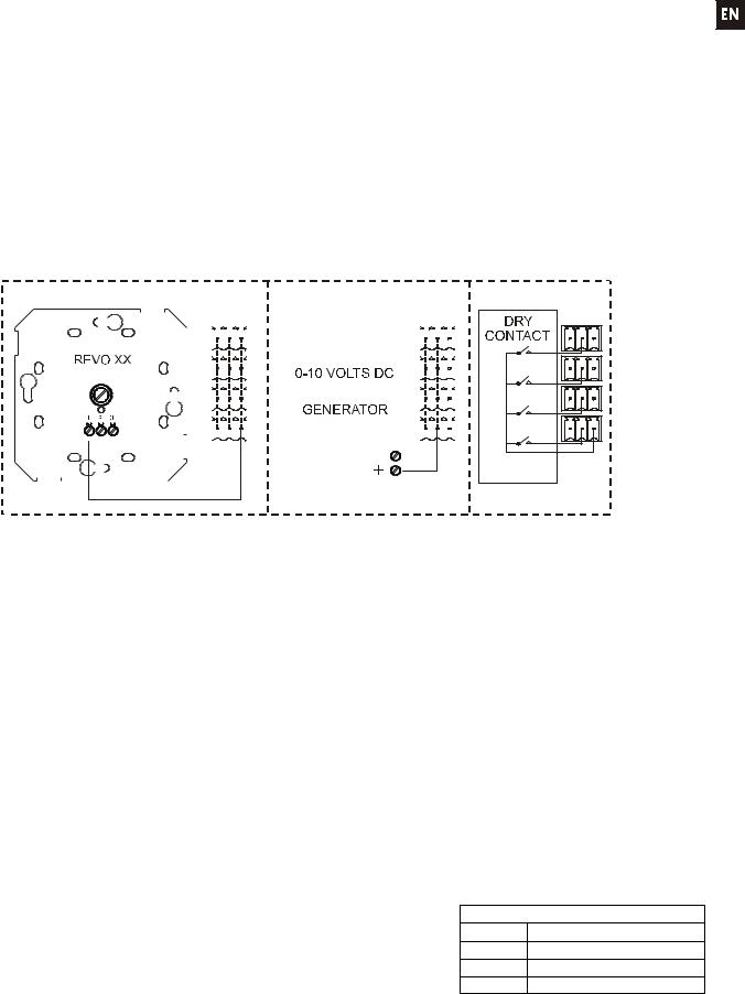
3.8. GPI Remote Control Ports
The rear panel of the MIMO88 offers 8 GPI inputs (16) for 0-10 VDC continuous control voltage. Each of these inputs can be connected to an external physical device (potentiometer, contact closure, continuously variable voltage 0-10V DC, etc.) and assigned to a MIMO88 function, as for example:
Input, output channel or matrix crosspoint volume remote control by means of a WPVOL physical knob or an Ecler WP Series WPVOL-IR remote control
MUTE or SOLO activation/deactivation by means of a switch or contact closure
Recalling a preset with a push button or contact closure
GPI connectors are screw terminal blocks with three-contacts. The wiring is as follows:
Positive, + 10 VDC |
> |
Pin + |
|
|
|
|
|
|
|
||||||||||||||||||||||||||||||
Variable voltage, 0-10 VDC |
> |
Pin |
|
|
|
|
|
|
|
||||||||||||||||||||||||||||||
Ground |
> |
Pin |
|
|
|
|
|
|
|
||||||||||||||||||||||||||||||
|
|
|
|
|
|
|
|
|
|
|
|
|
|
|
|
|
|
|
|
|
|
|
|
|
|
|
|
|
|
|
|
|
|
|
|
|
|
|
|
|
|
|
|
|
|
|
|
|
|
|
|
|
|
|
|
|
|
|
|
|
|
|
|
|
|
|
|
|
|
|
|
|
|
|
|
|
|
|
|
|
|
|
|
|
|
|
|
|
|
|
|
|
|
|
|
|
|
|
|
|
|
|
|
|
|
|
|
|
|
|
|
|
|
|
|
|
|
|
|
|
|
|
|
|
|
|
|
|
|
|
|
|
|
|
|
|
|
|
|
|
|
|
|
|
|
|
|
|
|
|
|
|
|
|
|
|
|
|
|
|
|
|
|
|
|
|
|
|
|
|
|
|
|
|
|
|
|
|
|
|
|
|
|
|
|
|
|
|
|
|
|
|
|
|
|
|
|
|
|
|
|
|
|
|
|
|
|
|
|
|
|
|
|
|
|
|
|
|
|
|
|
|
|
|
|
|
|
|
|
|
|
|
|
|
|
|
|
|
|
|
|
|
|
|
|
|
|
|
|
|
|
|
|
|
|
|
|
|
|
|
|
|
|
|
|
|
|
|
|
|
|
|
|
|
|
|
|
|
|
|
|
|
|
|
|
|
|
|
|
|
|
|
|
|
|
|
|
|
|
|
|
|
|
|
|
|
|
|
|
|
|
|
|
|
|
|
|
|
|
|
|
|
|
|
|
|
|
|
|
|
|
|
|
|
|
|
|
|
|
|
|
|
|
|
|
|
|
|
|
|
|
|
|
|
|
|
|
|
|
|
|
|
|
|
|
|
|
|
|
|
|
|
|
|
|
|
|
|
|
|
|
|
|
|
|
|
|
|
|
|
|
|
|
|
|
|
|
|
|
|
|
|
|
|
|
|
|
|
|
|
|
|
|
|
|
|
|
|
|
|
|
|
|
|
|
|
|
|
|
|
|
|
|
|
|
|
|
|
|
|
|
|
|
|
|
|
|
|
|
|
|
|
|
|
|
|
|
|
|
|
|
|
|
|
|
|
|
|
|
|
|
|
|
|
|
|
|
|
|
|
|
|
|
|
|
|
|
|
|
|
|
|
|
|
|
|
|
|
|
|
|
|
|
|
|
|
|
|
|
|
|
|
|
|
|
|
|
|
|
|
|
|
|
|
|
|
|
|
|
|
|
|
|
|
|
|
|
|
|
|
|
|
|
|
|
|
|
|
|
|
|
|
|
|
|
|
|
|
|
|
|
|
|
|
|
|
|
|
|
|
|
|
|
|
|
|
|
|
|
|
|
|
|
|
|
|
|
|
|
|
|
|
|
|
|
|
|
|
|
|
|
|
|
|
|
|
|
|
|
|
|
|
|
|
|
|
|
|
|
|
|
|
|
|
|
|
|
|
|
|
|
|
|
|
|
|
|
|
|
|
|
|
|
|
|
|
|
|
|
|
|
|
|
|
|
|
|
|
|
|
|
|
|
|
|
|
|
|
|
|
|
|
|
|
|
|
|
|
|
|
|
|
|
|
|
|
|
|
|
|
|
|
|
|
|
|
|
|
|
|
|
|
|
|
|
|
|
|
|
|
|
|
|
|
|
|
|
|
|
Examples of connection
Connecting cables can be up to 500 meters with a minimum section of 0.5 mm2.
Consult your ECLER dealer or www.ecler.com about the WP series remote control wall panels and other accessories available for connection to the REMOTE/VCA port.
3.9. GPO Remote Control Ports
The rear panel of the MIMO88 offers 8 NO/NC (normally open/ normally closed) relay outputs (17). Each of these outputs may be assigned to a MIMO88 function, such as a button of EclerNet Manager (MUTE key, SOLO key, etc.). This makes it possible to interact with external devices such as projection screen motors or movable partitions, lights, sirens, other equipment GPI entries, etc.3.10. Remote control RS-232 Port
3.10. Remote control RS-232 Port
The built-in RS-232 port in the rear panel allows an external device to communicate with an MIMO88 unit via a serial connection. Said connection uses the TP-NET protocol syntaxis so to enable the external device to obtain the value of any of the parameters of the MIM088 unit (by "GET" commands) and/or modify said values (“SET” commands). See the TP-NET protocol manual for more information.
The serial connection should comply with the following specifications: Baud rate: 57600 (fixed, no autonegotiation)
Data bits: 8 Parity: None Stop bits: 1
Flow control: None
WIRING RS232 – DB9
RS232 |
DB9 |
Tx |
Pin 2 (RxD) |
Rx |
Pin 3 (TxD) |
Gnd |
Pin 5 (Signal Gnd) |
7

3.11. Front panel controls and LED indicators
The following elements are available on the MIMO88 front panel:
MONITOR output (1) (marked with a headphones symbol): it produces the same monitoring signal already available via the rear panel screw terminal block, but here on a ¼" TRS jack and with a rotary volume control (2 ) for listening through headphones. It is especially useful for listening to input or output signals without disturbing the normal operation. In 16x16 mode both MIMO units receive the same signal. The monitored signal is selected with EclerNet Manager control software. Please refer to the EclerNet Manager software manual for more information.
Input LED indicators (3): indicate the presence of audio signal at the unit’s input, and its intensity level (green, amber and red indicate in this order the increased intensity level)
Output LED indicators (4): indicate the presence of audio signal at the unit’s output, and its intensity level (green, amber and red indicate in this order the increased intensity level)
Status LED indicators (STATUS):
oDATA: (5) Off: there is no connection to EclerNet Manager even if connected to Ethernet. On: connected to EclerNet Manager or to other third party application via TP-NET protocol. Flashing:
data traffic with EclerNet Manager or another application.
oLINK: (6)
1.If the device is configured as 8x8 MASTER, the LED is permanently off.
2.If the device is configured as 16x16 MASTER:
If everything is correct (SLAVE is connected and there is no communication error), the LED quickly and continuously toggles between green (50ms) and unlit (50ms)
If there is a communication error with the SLAVE, the LED quickly toggles between green (50ms) and red (200ms)
If no SLAVE is connected (or if connected equipment is another MASTER), the LED slowly toggles between green (800ms) and red (200ms)
3.If the device is configured as SLAVE:
If everything is correct (MASTER is connected and there is no communication error), the LED quickly and continuously toggles between orange (50ms) and unlit (50ms)
If there is a communication error with the MASTER, the LED quickly toggles between orange (50ms) and red (200ms)
If no MASTER is connected (or if connected equipment is another SLAVE), the LED slowly toggles between orange (800ms) and red (200ms)
oPOWER: (7) illuminates when the unit is in operation. It flashes if there is an error in the unit or if firmware is not correct. It also flashes when you update firmware
4.CLEANING
The front panel should not be cleaned with dissolvent or abrasive substances because silk-printing could be damaged. To clean it, use a soft cloth slightly wet with water and neutral liquid soap; dry it with a clean cloth. Be careful that water never gets into the unit through the holes of the front panel.
8

5. FUNCTION LIST
1.Headphones connection stereo jack
2.Volume control for the headphones output, VOL
3.Input signal indicators, INPUTS
4.Output signal indicators, OUTPUTS
5.Data traffic indicator, DATA
6.Link (with another unit) indicator, LINK
7.Power on indicator, POWER
8.Signal output screw terminal, OUT
9.Signal input screw terminal, IN
10.Signal output screw terminal, MONITOR
11.RJ-45 connector, ETHERNET
12.RJ-45 connector, LINK BUS
13.MASTER – SLAVE selector, MASTER SLAVE
14.Screw terminals for digital remote control, REMOTE
15.Screw-assembled remote control terminals via the TP-NET, RS-232 protocol
16.Screw terminals for continuous voltage control, GPI
17.Screw terminal for relay output, GPO
18.Mains socket
19.Fuse holder
20.Power switch
6. FUNCTION DIAGRAM
9
Explicación de los Símbolos Gráficos
El símbolo del relámpago con una flecha en la punta y dentro de un triangulo equilátero, tiene el propósito de alertar al usuario de la presencia de un voltaje peligroso y sin aislar dentro del aparato, y de una magnitud tal que puede constituir riesgo de descarga eléctrica para las personas.
El símbolo de exclamación dentro de un triangulo equilátero, tiene el propósito de alertar al usuario de la presencia de instrucciones importantes sobre la operación y mantenimiento en la información que viene con el producto.
Los símbolos de relámpagos dibujados cerca de los terminales de salida se utilizan para alertar al usuario del riesgo de descargas peligrosas. Los conectores de salida que podrían plantear algún riesgo se indican con este símbolo del relámpago. No toque los terminales de salida mientras que el amplificador esté encendido. Hacer todas las conexiones con el amplificador apagado.
ADVERTENCIA: para prevenir choques eléctricos o riesgo de incendios, no exponer este equipo a la lluvia o la humedad.
INSTRUCCIONES IMPORTANTES DE SEGURIDAD
1.Lea estas instrucciones
2.Guarde estas instrucciones
3.Preste atención a todas las advertencias
4.Siga todas las instrucciones
5.No utilice este aparato cerca del agua
6.Límpielo solamente con un paño seco
7.No bloquee ninguna abertura para ventilación. Instálelo de acuerdo con las instrucciones del fabricante
8.No lo instale cerca de fuentes de calor como radiadores, estufas u otros aparatos que produzcan calor, incluidos amplificadores.
9.No elimine el propósito de seguridad del cable de corriente polarizado o con conexión de tierra. Un cable polarizado tiene dos bornes, uno más ancho que el otro. Un enchufe con conexión a tierra, tiene dos bornes y un tercer borne conectado a tierra. Este tercer borne está previsto para su seguridad. Si el cable proporcionado no entra en su enchufe, consulte con un técnico electricista para reemplazar ese enchufe obsoleto.
10.Proteja el cable eléctrico de ser aplastado, en especial en la zona de los conectores, los receptáculos de los mismos y en el punto en el que el cable sale del aparato.
11.Utilice solamente los accesorios especificados por el fabricante.
12.Desconecte el aparato durante las tormentas eléctricas o cuando no lo vaya a usar durante periodos largos de tiempo.
13.Para cualquier reparación, póngase en contacto con un servicio técnico cualificado. La reparación es necesaria cuando el aparato no funciona con normalidad o ha sido dañado por cualquier motivo, ya sea porque el cable o el enchufe estén dañados, porque se hayan derramado líquidos o hayan caído objetos dentro del aparato, o porque el aparato haya sido expuesto a la lluvia o se haya caído.
14.Desconexión de la red: apagando el interruptor de POWER (14) todas las funciones e indicadores del amplificador se pararán, pero la completa desconexión del aparato se consigue desconectando el cable de red de su conector (37). Por esta razón, éste siempre debe tener fácil acceso.
10
ÍNDICE |
|
|
1. NOTA IMPORTANTE |
12 |
|
|
||
|
||
1.1. Precauciones |
12 |
|
2. INTRODUCCIÓN |
12 |
|
3. INSTALACIÓN |
13 |
|
3.1. Ubicación, montaje, ventilación |
13 |
|
3.2. Conexión a red eléctrica y encendido |
13 |
|
3.3. Conexiones de entrada de señal |
13 |
|
3.4. Conexiones de audio de salida |
13 |
|
3.5. Puerto ETHERNET de programación y control |
14 |
|
3.6. Puerto LINK BUS de enlace de audio digital |
14 |
|
3.7. Puertos REMOTE 1 y 2 para controles remotos digitales |
14 |
|
3.8. Puertos GPI de control remoto |
15 |
|
3.9. Puertos GPO de control remoto |
15 |
|
3.10. Puerto RS-232 de control remoto |
15 |
|
3.11. Controles e indicadores LED del panel frontal |
16 |
|
4. LIMPIEZA |
16 |
|
5. LISTA DE FUNCIONES |
17 |
|
6. DIAGRAMA DE FUNCIONAMIENTO |
17 |
|
7. CARACTERÍSTICAS TÉCNICAS |
34 |
|
8. DIAGRAMA DE BLOQUES |
38 |
|
Todos los datos están sujetos a variación debida a tolerancias de producción. ECLER S.A. se reserva el derecho de realizar cambios o mejoras en la fabricación o diseño que pudieran afectar las especificaciones.
11

1. NOTA IMPORTANTE
Agradecemos su confianza por haber elegido nuestra matriz MIMO88. Para conseguir la máxima operatividad y rendimiento de su equipo es MUY IMPORTANTE, antes de su conexión, leer detenidamente y tener muy presentes las consideraciones que en este manual se especifican.
Para garantizar el óptimo funcionamiento de este aparato recomendamos que su mantenimiento sea llevado a cabo por nuestros Servicios Técnicos autorizados.
El MIMO88 tiene una garantía de 3 años.
1.1. Precauciones
Este aparato debe ser conectado a tierra mediante su cable de alimentación.
No exponga el aparato a la caída de agua o salpicaduras, no ponga encima objetos con líquido ni fuentes de llama desnuda, como velas.
En caso de requerir alguna intervención y/o conexión desconexión del aparato debe desconectarse previamente de la alimentación.
En el interior del aparato no existen elementos manipulables por el usuario.
2. INTRODUCCIÓN
MIMO88 es una matriz digital de audio, totalmente programable y con las siguientes características principales:
8 entradas MICRO/LÍNEA simétricas (alimentación Phantom independiente por canal de entrada).
8 salidas de LÍNEA simétricas.
2 salidas de MONITOR que se pueden utilizar como auxiliares.
Expandible a 16 entradas / 16 salidas enlazando una segunda unidad MIMO88 (obteniendo una matriz real de 16 entradas y 16 salidas). Enlace entre unidades mediante cable CAT5 cruzado (100 metros de distancia máxima).
8 puertos de control GPI (General Purpose Input).
8 puertos de control GPO (General Purpose Output).
Programación y gestión remota vía Ethernet mediante aplicación EclerNet Manager (bien punto a punto, con cable CAT5 directo, bien desde un puesto de red Ethernet).
Control remoto mediante clientes Ethernet de EclerNet Manager: clientes simultáneos con panel de control personalizado.
Control remoto desde dispositivos externos de terceros. (Crestron, AMX, Vity, Medialon, etc. Marcas registradas por sus fabricantes). Protocolo TP-NET, mediante puertos Ethernet o RS-232.
Bus de control remoto para paneles digitales WPTOUCH y consolas de mensajes (paging) MPAGE16.
Gestión de memorias de configuración (presets).
Eventos programados en base a calendario.
Amplio procesamiento DSP disponible:
oMatriz encaminadora-mezcladora, desde cualquier entrada hacia cualquier salida con nivel de puntos de cruce ajustable (mezclas independientes de diferentes entradas para
cada salida).
o Tratamiento de canales en modo mono o estéreo.
o Nivel, enmudecimiento, vu-metros y ajuste de fase en entradas y salidas.
o Generador de señal interno (señal senoidal, ruido rosa, ruido blanco, test de polaridad). o EQ paramétrica en entradas y en salidas.
o Retardos en entradas y en salidas.
o Puerta de ruido / compresor en canales de entrada. o Compresor / limitador en salidas.
o Prioridades (ducking) entre canales de entrada.
o Consolas de mensajes (paging) virtuales y físicas. o Mezclador automático.
La programación del MIMO88 se realiza mediante la aplicación EclerNet Manager*. Consulte el manual de la Aplicación EclerNet Manager para obtener más información.
* La aplicación EclerNet Manager se encuentra disponible para su descarga en www.ecler.com.
12
 Loading...