


SkyView
Pilot’s User Guide
This product is not TSO’d and cannot be installed into traditional FAA Part 23 and similarly typecertificated aircraft.
Document 101321-018, Revision S
For use with firmware version 12.0
January, 2015
Copyright © 2009-2015 by Dynon Avionics, Inc.
Permission to print this manual is granted to third parties
Contact Information
Dynon Avionics, Inc.
19825 141st Place NE Woodinville, WA 98072
Phone: (425) 402-0433 - 8:00 AM – 5:00 PM (Pacific Time) Monday – Friday
Dynon Technical Support available 7:00 AM–4:00 PM (Pacific Time) Monday – Friday Email: support@dynonavionics.com
Fax: (425) 984-1751
Dynon Avionics offers online sales, extensive support, and frequently updated information on its products via its Internet sites:
www.dynonavionics.com – Dynon Avionics primary web site; including:
docs.dynonavionics.com – Current and archival documentation.
downloads.dynonavionics.com – Software downloads.
support.dynonavionics.com – Support resources.
store.dynonavionics.com – Dynon’s secure online store for purchasing all Dynon products 24 hours a day.
wiki.dynonavionics.com – Dynon’s Documentation Wiki provides additional technical information on Dynon products.
forum.dynonavionics.com – Dynon’s Internet forum where Dynon customers can interact with each other and Dynon Avionics. A key feature of the forum is that it allows the exchange of diagrams, photos, and other types of files.
newsletter.dynonavionics.com – Dynon’s email newsletter.
preflight.dynonavionics.com – A collection of educational articles, tips, news, and “behind the panel” information about Dynon and its products.
register.dynonavionics.com – Register your Dynon Avionics product.
license.dynonavionics.com – Redeem certificates for Navigation Mapping Software, Synthetic Vision, and other features for license codes that add new functionality to your SkyView system.
Copyright
2008-2015 Dynon Avionics, Inc. All rights reserved. No part of this manual may be reproduced, copied, transmitted, disseminated or stored in any storage medium, for any purpose without the express written permission of Dynon Avionics. Dynon Avionics hereby grants permission to download a single copy of this manual and of any revision to this manual onto a hard drive or other electronic storage medium to be viewed for personal use, provided that such electronic or printed copy of this manual or revision must contain the complete text of this copyright notice and provided further that any unauthorized commercial distribution of this manual or any revision hereto is strictly prohibited.
Information in this document is subject to change without notice. Dynon Avionics reserves the right to change or improve its products and to make changes in the content without obligation to notify any person or organization of such changes. Visit the Dynon Avionics website (www.dynonavionics.com) for current updates and supplemental information concerning the use and operation of this and other Dynon Avionics products.
Limited Warranty
Dynon Avionics warrants this product to be free from defects in materials and workmanship for three years from date of shipment. Dynon Avionics will, at its sole option, repair or replace any components that fail in normal use. Such repairs or replacement will be made at no charge to the customer for parts or labor performed by Dynon Avionics. The customer is, however, responsible for any transportation cost and any costs that are incurred while removing, reinstalling, or troubleshooting the product. This warranty does not cover failures due to abuse, misuse, accident, improper installation or unauthorized alteration or repairs.
THE WARRANTIES AND REMEDIES CONTAINED HEREIN ARE EXCLUSIVE, AND IN LIEU OF ALL OTHER WARRANTIES EXPRESSED OR IMPLIED, INCLUDING ANY LIABILITY ARISING UNDER WARRANTY OF MERCHANTABILITY OR FITNESS FOR A PARTICULAR PURPOSE, STATUTORY OR OTHERWISE. THIS WARRANTY GIVES YOU SPECIFIC LEGAL RIGHTS, WHICH MAY VARY FROM STATE TO STATE AND IN COUNTRIES OTHER THAN THE USA.

IN NO EVENT SHALL DYNON AVIONICS BE LIABLE FOR ANY INCIDENTAL, SPECIAL, INDIRECT OR CONSEQUENTIAL DAMAGES, WHETHER RESULTING FROM THE USE, MISUSE OR INABILITY TO USE THIS PRODUCT OR FROM DEFECTS IN THE PRODUCT. SOME STATES AND COUNTRIES DO NOT ALLOW THE EXCLUSION OF INCIDENTAL OR CONSEQUENTIAL DAMAGES, SO THE ABOVE LIMITATIONS MAY NOT APPLY TO YOU.
Dynon Avionics retains the exclusive right to repair or replace the instrument or firmware or offer a full refund of the purchase price at its sole discretion. SUCH REMEDY SHALL BE YOUR SOLE AND EXCLUSIVE REMEDY FOR ANY BREACH OF WARRANTY.
These instruments are not intended for use in type certificated aircraft at this time. Dynon Avionics makes no claim as to the suitability of its products in connection with FAR 91.205.
Dynon Avionics’ products incorporate a variety of precise, sensitive electronics. SkyView products do not contain any field/user-serviceable parts. Units found to have been taken apart may not be eligible for repair under warranty. Additionally, once a Dynon Avionics unit is opened up, it is not considered airworthy and must be serviced at the factory.
iv |
SkyView Pilot’s User Guide |

|
|
|
|
|
Revision History |
|
|
Revision |
|
Revision Date |
|
Description |
|
|
A |
|
December 2009 |
|
Initial release |
|
|
|
|
|
|
|
|
|
|
|
|
|
Document number changed to 101321-001. |
|
|
|
|
|
|
Minor style, grammar, and cross reference changes and corrections. |
|
|
|
|
|
|
Added information regarding Autopilot servos in applicable sections. |
|
|
|
|
|
|
Addressed screen synchronization in applicable sections. |
|
|
|
|
|
|
SV-D700 and SV-D1000 Operation Chapter updates: |
|
|
|
|
|
|
|
Added the Menu Navigation Section |
|
|
|
|
|
|
Clarified the How to Turn the System On or Off Section |
|
|
|
|
|
|
Expanded the How to Manually Adjust the Backlight Brightness or Dim Level |
|
|
|
|
|
|
Section |
|
|
|
|
|
|
Expanded the How to Enter the Joystick Function Menu Section |
|
B |
|
March 2010 |
|
|
Added the How to Check Installed Database Statuses Section |
|
|
|
|
Added the How to Configure the Top Bar Section |
||
|
|
|
|
|
||
|
|
|
|
|
PFD Operation Chapter updates: |
|
|
|
|
|
|
|
Added the ADAHRS Source Section |
|
|
|
|
|
|
Added the GPS Source Section |
|
|
|
|
|
|
Added “push to synchronize” instructions for applicable bugs |
|
|
|
|
|
Moving Map Operation Chapter updates: |
|
|
|
|
|
|
|
Added an important note regarding Moving Map requirements |
|
|
|
|
|
|
Added the GPS Source Section |
|
|
|
|
|
|
Added the Terrain Data Section |
|
|
|
|
|
|
Added the Aviation Data Section |
|
|
|
|
|
Corrected the Onscreen Alerts Section in the Alerts Chapter. |
|
|
|
|
|
|
|
|
|
|
|
|
|
Document number changed to 101321-002. |
|
|
|
|
|
|
Minor style and grammar changes and corrections. |
|
|
C |
|
May 2010 |
|
Updated the guide to include HSI operation information. |
|
|
|
|
|
|
Updated the guide to include Autopilot operation information. |
|
|
|
|
|
|
Updated the guide with more Moving Map content. |
|
|
|
|
|
|
|
|
|
|
|
|
|
Document number changed to 101321-003. |
|
|
|
|
|
|
Clarified intended use of Synthetic Vision. |
|
|
|
|
|
|
Added information about Synthetic Vision depictions of runways and obstacles. |
|
|
D |
|
June 2010 |
|
Added EMS menu, lean mode, engine timers, and fuel computer information. |
|
|
|
|
Clarified map Magnetic North pointer. |
|||
|
|
|
|
|
||
|
|
|
|
|
Added Navigation Mapping Software information. |
|
|
|
|
|
|
Added Trial Navigation Mapping Software information and operation instructions. |
|
|
|
|
|
|
Added external alarm light behavior. |
|
|
|
|
|
|
|
|
SkyView Pilot’s User Guide - Revision S |
v |

|
Revision |
|
Revision Date |
|
Description |
|
|
|
|
|
Added information about User Waypoint power user feature that is fully documented on |
|
|
|
|
|
wiki web page. |
|
|
|
|
|
Added information about menu changes that may be present in SLSA and other aircraft |
|
|
|
|
|
that SkyView is integrated into as an OEM component. |
|
E |
|
October 2010 |
|
Added transponder operation information and specifications. |
|
|
|
|
||
|
|
|
|
|
Added traffic display information for both MAP and PFD pages. |
|
|
|
|
|
Added a better description of the combined EGT/CHT gauge. |
|
|
|
|
|
Added Synthetic Vision licensing information. |
|
|
|
|
|
Added Navigation Mapping Software Licensing and updated operation information. |
|
|
|
|
|
|
|
|
|
|
|
Revision F skipped to obtain version parity between Installation Guide and Pilot’s User |
|
|
|
|
|
Guide. |
|
|
|
|
|
Added description of GPS Steering control of Autopilot. |
|
|
|
|
|
Pitch Trim Indicator behavior and performance expectations clarified. |
|
G |
|
March 2011 |
|
Added servo weights. |
|
|
|
Added product registration information. |
||
|
|
|
|
|
|
|
|
|
|
|
Described improved loss of external power with backup battery connected behavior. |
|
|
|
|
|
Added information about G Meter. |
|
|
|
|
|
Added information about new/improved Navigation Mapping Software purchase, |
|
|
|
|
|
licensing, and operation. |
|
|
|
|
|
|
|
|
|
|
|
Added description of enabling/disabling extreme pitch warning indicators and Flight Path |
|
|
|
|
|
Marker. |
|
|
|
|
|
Updated screen layout button labeling and figures |
|
|
|
|
|
Added information on Flight Planning. |
|
|
|
|
|
Updated several of the figures that were no longer valid due to button and screen |
|
H |
|
May 2011 |
|
changes. |
|
|
|
|
||
|
|
|
|
|
Changes made for new style of heading bug and heading readout. |
|
|
|
|
|
Screen Hardware changed to Display Hardware. |
|
|
|
|
|
Added section on autopilot safety features. |
|
|
|
|
|
Added additional information about airport graphics. |
|
|
|
|
|
Added additional information to SV-ADAHRS-20X Instruments and Sensors table. |
|
|
|
|
|
|
|
|
|
|
|
Added description of improved bug window outlining (when selected) and cyan |
|
|
|
|
|
highlighting (when being adjusted). |
|
|
|
|
|
Added “Show VOR Directions As” menu item description. |
|
|
|
|
|
Added Vertical Power VP-X information. |
|
|
|
|
|
Clarified SV-BAT-320 charging behavior; Clarified which devices and modules the SV-BAT- |
|
I |
|
September 2011 |
|
320 is capable of powering. |
|
|
|
|
||
|
|
|
|
|
Added permission to print the manual. |
|
|
|
|
|
Added map panning information. |
|
|
|
|
|
Remove erroneous checkmark in AOA column in winds row in “Instruments and Sensors “ |
|
|
|
|
|
table. |
|
|
|
|
|
Improved HSI information. |
|
|
|
|
|
|
vi |
SkyView Pilot’s User Guide |

|
Revision |
|
Revision Date |
|
Description |
|
|
|
|
|
Clarified that Jeppesen data must be transferred to USB stick via the Jeppesen JSUM |
|
|
|
|
|
program. |
|
|
|
|
|
Added PocketFMS information. |
|
|
|
|
|
Clarified bearing sources and limitations (SBY bearings from some NAV radios and no |
|
|
|
|
|
availability of bearings from LOCs). |
|
|
|
|
|
Clarified EMS timers. |
|
J |
|
March 2012 |
|
Added special Rotax 912 tachometer and oil temp behavior when configured. |
|
|
|
|
|
|
|
|
|
|
|
Added altitude alerter information. |
|
|
|
|
|
Refreshed Messages and Alerts section to reflect feature improvements. |
|
|
|
|
|
Added Audio Alert information. |
|
|
|
|
|
Updated map instructions to reflect UI refresh, improved info items support, user |
|
|
|
|
|
waypoints, and visual reporting points support. |
|
|
|
|
|
|
|
|
|
|
|
Clarified engaging the Autopilot with the Disengage/CWS Button. |
|
|
|
|
|
Added information about when airspeed indication comes alive. |
|
K |
|
July 2012 |
|
Added SkyView Network redundancy information. |
|
|
|
|
||
|
|
|
|
|
Added ADAHRS cross-checking information. |
|
|
|
|
|
Updated Navigation Mapping Software to incorporate base map support and airspace |
|
|
|
|
|
improvements. |
|
|
|
|
|
|
|
|
|
|
|
Updated Screen Layout Configuration section to add information about display swap |
|
|
|
|
|
mode and reversion mode. |
|
|
|
|
|
Added information about DA calculation. |
|
|
|
|
|
Added engine alert inhibit information. |
|
|
|
|
|
Added information about normal display artifacts on power on. |
|
|
|
|
|
Updated recommendation to have servos powered whenever SkyView is powered on. |
|
|
|
|
|
Added description of take-off position marking for trim widget. |
|
L |
|
December 2012 |
|
Added information about attitude rate limit indications. |
|
|
|
Rearranged PFD Operation section for better information flow. |
||
|
|
|
|
|
|
|
|
|
|
|
Added SV-XPNDR-26X, SV-ADSB-470 information to system overview. |
|
|
|
|
|
Added ADS-B and Flarm traffic information. |
|
|
|
|
|
User waypoint altitude information now displayed on their Info pages. |
|
|
|
|
|
Added information about the AUTO transponder setting when automatic ALT/GND mode |
|
|
|
|
|
changes are enabled (only available with transponder software version 2.02 or above). |
|
|
|
|
|
Detailed improvements to ENGINE > FUEL UI. |
|
|
|
|
|
Added information about weather features and usage via SV-ADSB-470. |
|
|
|
|
|
|
|
|
|
|
|
Added information about Data Logging. |
|
M |
|
January 2013 |
|
Added information about Stadium TFRs. |
|
|
|
Added TACAN and Outer Marker symbols. |
||
|
|
|
|
|
|
|
|
|
|
|
Clarified information about the AIRSPACES BELOW feature in the Map Menu. |
|
|
|
|
|
|
SkyView Pilot’s User Guide - Revision S |
vii |

|
Revision |
|
Revision Date |
|
Description |
|
|
|
|
|
Added MDA bug information. |
|
|
|
|
|
Updated PFD Bugs section with new bug names. |
|
|
|
|
|
Updated information regarding how the Flight Path Marker is displayed. |
|
|
|
|
|
Revised GPS 0 position source information, now labeled SkyView. |
|
|
|
|
|
Added Map Trial Mode – Trial Expired description. |
|
|
|
|
|
Added Map Aviation Database Expired description. |
|
N |
|
June 2013 |
|
Added Garmin GTX 330ES transponder support for activating ADS-B traffic. |
|
|
|
Revised “Show Airspaces Below” description. |
||
|
|
|
|
|
|
|
|
|
|
|
Added Traffic Fail announcement description. |
|
|
|
|
|
Added Battery status/test information. |
|
|
|
|
|
Revised Autopilot chapter to reflect new Simplified and Expert Autopilot Control schemes. |
|
|
|
|
|
Added COM Radio Chapter. |
|
|
|
|
|
Revised Messages, Alerts, and Audio Alert Details. |
|
|
|
|
|
Added information about Backup Battery status information and testing capabilities. |
|
|
|
|
|
|
|
|
|
|
|
Center click can now be used to pull up, set, and sync (by holding) the PFD joystick |
|
|
|
|
|
functions menus (bugs, baro, crs, etc.). |
|
|
|
|
|
Added new Up/Down Timers feature. |
|
|
|
|
|
Added new Fuel Tank Reminder alert. |
|
|
|
|
|
Added Geo-referenced Approach/Departure Charts and Airport Diagrams feature for US |
|
O |
|
September 2013 |
|
Data. |
|
|
|
Updated Navigation Mapping Software chapter to reflect refined direct-to and flight |
||
|
|
|
|
|
|
|
|
|
|
|
planning behaviors. Minor changes. |
|
|
|
|
|
Added new Map Pointer selection features. |
|
|
|
|
|
Clarified new shortcut of using Nose Up and Nose Down buttons to immediately start a |
|
|
|
|
|
climb/descent from Alt Hold mode in Expert Autopilot. |
|
|
|
|
|
Added audio alert inhibition upon SkyView startup information. |
|
|
|
|
|
|
|
|
|
|
|
Added Geo-referenced Approach/Departure Charts and Airport Diagrams feature for |
|
|
|
|
|
Europe data. |
|
|
|
|
|
Added procedure for downloading Europe Chart data. |
|
P |
|
November 2013 |
|
Added information about ICAO and FAA flight plan codes in the Transponder Operation |
|
|
|
|
|
|
|
|
|
|
|
section. |
|
|
|
|
|
Modified procedure chart FOLLOW behavior description (follow mode now default s to on |
|
|
|
|
|
for airport diagrams). |
|
|
|
|
|
|
viii |
SkyView Pilot’s User Guide |

Revision |
Revision Date |
Description |
Added: Information about SV-INTERCOM-2S
Added: Support for SkyView Touch.
Added: Enroute charts, including VFR, IFR LO and HI. US support via existing Seattle
Avionics Subscriptions at release.
Clarified: GPS assist in Attitude Calculation
Clarified: magnetic heading is not used to aid attitude determination
Added: Support for dual engine monitoring by using two SV-EMS-22X modules.
Added: Support to monitor up to 28 total EGT and/or CHTs by using a second SV-EMS-22X module.
Clarified: Navigation Mapping Software required to view charts on SkyView
Clarified: SV-COM-C25 product description
Added: Support for SV-KNOB-PANEL dedicated knob control panel.
Added: Support for SV-AP-PANEL dedicated autopilot control panel.
Clarified: Top Bar status area configuration
Added: 60% PFD Screen layout option when paired with 40% Map
Added: Vertical Speed Required to destination Info Item on map and PFD VSI displays the current VS required to set up at a specified point at or before and above your final destination waypoint.
Improved: GPS waypoints now displayed in HSI info area for ARINC navigators such as the
GNS and GTN.
Improved: External GPS and nav radios can now be named with a user-configurable 7 character “friendly name” to aid in identifying sources on the HSI display.
Q |
March 2014 |
Moved: Synthetic Vision description within the PFD Chapter
Added: Conventional analog “six-pack” display mode for primary flight instruments.
Changed: PFD menu now includes MODE button to select between EFIS or Analog presentation and to toggle SynVis on or off
Added: HSI Source Button is duplicated in the Autopilot Menu for convenience.
Added: Support for showing Flight plans from ARINC IFR GPS navigators such as the GNS and GTN series both on SkyView’s map (including holds and other procedure turns) and on SkyView’s flight plan display.
Improved: Timer expiration in top bar changed from yellow to white
Improved: All EMS widgets that have assignable color ranges (red/yellow/green/black) now have additional color options: blue, white, purple, cyan, and orange.
Changed: All EMS timers that formerly had “flight” or “flt” in their names are now called “air” timers. The underlying behavior of these timers has not changed.
Improved: Fuel Tank Switch Reminder is now based on Flight Time and not engine Run
Time.
Improved: Press and holding knob/joystick center-click from within the FPL menu brings up the insert waypoint function.
Improved: When the map pointer is selecting a single item, range is still enabled by turning the map joystick knob (if two or more items are under the pointer, turning the knob chooses which one is selected).
Improved: Yellow/red terrain alert coloration disabled on the map page when not in flight.
Fixed: “Show Airspaces Below” feature did not always properly exclude airspaces whose altitudes were defined by flight levels (primarily in non-US data).
SkyView Pilot’s User Guide - Revision S |
ix |

|
Revision |
|
Revision Date |
|
Description |
|
|
|
|
|
Added: Support for MGL V6 and V10 Com radios. |
|
|
|
|
|
Added: Support for the Trig TY91 Com radio. |
|
|
|
|
|
Added: Support for Val NAV 2000 nav radio. |
|
|
|
|
|
Improved: Radios such as the Icom A210 that can receive frequencies but do not output |
|
|
|
|
|
status now need not cause the top bar radio status area to show a “red x”. Added |
|
|
|
|
|
DISPLAY COM IN TOP BAR option to configure this behavior. |
|
|
|
|
|
Fixed: Fuel Tank Switch Reminder is now a message, not a caution alert. |
|
|
|
|
|
Added: Touch Panel Fault Alert |
|
|
|
|
|
Added: Special alert behavior for Dual Engine monitoring |
|
|
|
|
|
Added: “Check gear” and “gear overspeed” audio alerts for retractable gear aircraft that |
|
|
|
|
|
are tied to both landing gear status and airspeeds. |
|
|
|
|
|
Added: “Gear up for water landing” and “gear down for runway landing” audio alerts for |
|
|
|
|
|
amphibious aircraft that are annunciated as a selected airspeed is transitioned through. |
|
Q (Cont.) |
|
March 2014 |
|
Added: Tail numbers for ADS-B equipped traffic will be shown below traffic targets when |
|
|
|
|
|
|
|
|
|
|
|
available. Only available for aircraft equipped with Dynon's ADS-B receiver, and will only |
|
|
|
|
|
be shown for target aircraft that are ADS-B OUT equipped. |
|
|
|
|
|
Improved: Radios such as the Icom A210 that can receive frequencies but do not output |
|
|
|
|
|
status now need not cause the top bar radio status area to show a “red x”. Added |
|
|
|
|
|
DISPLAY COM IN TOP BAR option to configure this behavior. |
|
|
|
|
|
Fixed: Warning, caution, and message alerts that do not have their own dedicated audio |
|
|
|
|
|
phrases were not annunciating the generic “warning”, “caution”, and “message” audio |
|
|
|
|
|
phrases they should have been. This bug is present in SkyView 7.0-7.1. It worked properly |
|
|
|
|
|
previously and is fixed with 10.0. |
|
|
|
|
|
Fixed: Items that shouldn’t be appearing on the map per the “map items” zoom/range |
|
|
|
|
|
declutter settings were appearing when the map was very zoomed in. |
|
|
|
|
|
New: Support for speed-scheduling of the trim control in the SV-AP-PANEL. |
|
|
|
|
|
Improved: HSI courses are now remembered for each HSI source. This is especially helpful |
|
|
|
|
|
when switching between VOR and ILS or GPS and ILS sources. |
|
|
|
|
|
|
|
|
|
|
|
New: Support for SV-COM-X83 8.33 kHz COM radio. |
|
|
|
|
|
New: Support for Video Input Adapter. Allows display of video via NTSC and PAL S-Video |
|
|
|
|
|
and composite connections. Note: Only compatible with SkyView Touch and newer |
|
|
|
|
|
SkyView SV-D1000 (s/n >= 6000) and SV-D700 (s/n >= 4000) displays. |
|
|
|
|
|
New: Virtual-DME (non-certified) distance to VORs via GPS when the VOR identifier is |
|
|
|
|
|
known. Magenta distance is displayed on HSI info area on PFD. |
|
|
|
|
|
New: SHOW AIRSPACES WITHIN XXXX FT option to declutter airspaces that aren’t a factor |
|
|
|
|
|
at the current aircraft altitude. |
|
R |
|
August 2014 |
|
New: Wide field of view option for Synthetic Vision under PFD > MODE > WIDE. Setting |
|
|
|
also proportionately scales the pitch ladder. |
||
|
|
|
|
|
|
|
|
|
|
|
New: Vne can now be set as TAS. |
|
|
|
|
|
New: Option to turn on color-coded weather “dots” at airports with METARS via MAP |
|
|
|
|
|
MENU > WEATHER OPTIONS > METAR ICONS (SV-ADSB-470 required). |
|
|
|
|
|
New: BARO sync will now obtain either the nearest METAR (when ADS-B is available in- |
|
|
|
|
|
flight), set to 29.92 (when at/above 18k feet or no ADS-B on board), or to make the |
|
|
|
|
|
altimeter match GPS altitude (when on the ground). |
|
|
|
|
|
Added: Alert when engine sensor definitions do not match across multiple displays in a |
|
|
|
|
|
SkyView system. |
|
|
|
|
|
|
x |
SkyView Pilot’s User Guide |
Revision |
Revision Date |
Description |
|
|
Added: Caution alert if transponder hex code is not set. |
|
|
Added: Option to alert the pilot when the current BARO setting and the nearest METAR- |
|
|
based altimeter setting are significantly different (requires SV-ADSB-470). |
|
|
Added: Audible “AUTOPILOT” callout when the autopilot is engaged. |
|
|
Added: Alerts when SV-AP-PANEL, or SV-KNOB-PANEL go offline. |
|
|
Added: Alert when an external Level button is connected and detected stuck at boot. |
|
|
Added: GPS-based distances to bearing sources in HSI info area (when only one bearing |
|
|
source is displayed). |
|
|
Added: Alert for detectable audio subsystem failures. |
|
|
Added: MAP MENU > FLIGHT PLAN OPTIONS > PLAN GROUND SPEED lets SkyView |
|
|
perform ETE, ETA, and other speed-dependent calculations at a user-specified ground |
|
|
speed when not flying. |
|
|
Improved: Traffic service/device reception quality indicator on map page. |
R (cont.) |
August 2014 |
Improved: Additional failure detection and annunciation of rate sensors, accelerometers, |
|
|
and pressure transducers in the SV-ADAHRS-20X. |
|
|
Improved: Alert that annunciates when there is no high-res terrain available for the |
|
|
current aircraft location (usually because a different world region is loaded). |
|
|
Improved: Joystick knob menu now annunciates successful sync of any bug or BARO |
|
|
setting when you press/hold the joystick knob. |
|
|
Improved: Bugs can now be turned on and off per display via PFD>BUGS. The presence of |
|
|
an autopilot no longer forces all bugs to be shown on all displays. |
|
|
Improved: Display dimming algorithm and menu control scheme improved to disallow |
|
|
brightness settings that would result in an illegible (too dim) display. |
|
|
Improved: Airport identifiers on MAP are now white to improve legibility. |
|
|
Improved: PFD>XPNDR menu no longer has a time-out that automatically backs out of |
|
|
menu. |
|
|
Improved: ROP/LOP EMS info widget now says “PK?” instead of “UND” when calculation |
|
|
is out of range or not possible for the configuration. |
|
|
|
|
|
New: Autopilot Auto-Trim. The SkyView AutoPilot can automatically re-trim the aircraft as |
|
|
it flies under autopilot control. This feature requires that the aircraft has an SV-AP-PANEL |
|
|
and is using its integrated trim controller for trim servo actuation. |
|
|
New: OBS Mode that allows pilots easily set and adjust an inbound course to any |
|
|
navigable point on the map. That inbound course may then be easily adjusted with the |
|
|
HSI CRS knob, similar to how one would with a VOR. This is useful to approach an airport |
|
|
from a specific direction, for example, without having to create a second waypoint to |
|
|
create a full flight plan leg. |
|
|
New: Aircraft icon displayed on the Map and in the HSI PFD can be changed to one of over |
S |
January 2015 |
a dozen types of aircraft. |
|
|
Added: Alerts that let the pilot know if the CPU within SkyView's display is overheating |
|
|
due to failure of SkyView's thermal dissipation features. |
|
|
Added: New option under MAP MENU > MAP ITEMS > TFR OPACITY that allows pilots to |
|
|
change the opacity of TFRs. This can be used to tune the visibility of co-located TFRs and |
|
|
underlying map features. |
|
|
Added: Support for sending/receiving frequencies to the Garmin GTR-200. This does not |
|
|
include the ability to send aviation database information to the GTR-200. |
|
|
|
SkyView Pilot’s User Guide - Revision S |
xi |

Revision |
Revision Date |
Description |
|
|
Improved: When starting navigation via the "direct-to" feature, SkyView now anticipates |
|
|
the initial turn (if ones is required) and starts navigating from the end of that initial turn. |
|
|
This eliminates s-turning after the initial turn towards the "direct-to" destination. |
|
|
Improved: Video input can be flipped horizontally and/or vertically. |
|
|
Improved: Since "ON" mode is almost never used in mode-S operations, and pilots using |
|
|
that mode likely intend to be in ALT, a XPNDR NOT IN ALT MODE alert is presented |
|
|
whenever the SV-XPNDR-26X has been in "ON" mode for >5 seconds. |
|
|
Improved: Notification when SV-BAT-320 is severely discharged upon boot. This is most |
|
|
likely to occur immediately after performing the yearly battery rundown test. |
|
|
Improved: GPS location now sent to GNC 255 and GTR 225 radios to enable their ability to |
|
|
look up aviation features from their self-contained databases. |
|
|
Improved: XPNDR HEX CODE NOT SET alert now provided whenever an ADS-B receiver is |
|
|
installed but a valid HEX code is not set. |
|
|
Improved: MAP joystick/knob function can be set to either the left of right joystick/knob |
|
|
when MAP is full-screen (100% Page). |
|
|
Improved: Map zoom/range feature can be reversed so that clockwise rotation "zooms |
|
|
in" to the map (decreases range) to suit user preference. |
|
|
Improved: IAS bug now shown on six-pack PFD page. |
|
|
Improved: EGTs and CHTs that are displaying a "red X" due to probe failure no longer |
|
|
show a railed pictorial value on the analog graph graphical display. |
|
|
Improved: When a GTN or GNS series ARINC navigator is in GPS OBS mode, the selected |
|
|
inbound course to the waypoint being navigated to is depicted on SkyView's map when |
|
|
that navigator's flight plan the displayed map. |
S (cont.) |
January 2015 |
Improved: Display auto-dimming improved to improve behavior during light changes such |
|
|
as when a flashlight is used at night. |
|
|
Improved: Runways with unknown length are not shown when NRST list is being filtered |
|
|
by runway length. |
|
|
Improved: Automatic switching of AIR and GROUND modes for the SV-26X-XPNDR when |
|
|
flying at low airspeed. |
|
|
Improved: "GAMI"-style fuel flow spread is now always displayed in GPH to follow usage |
|
|
convention. |
|
|
Improved: PFD pitch ladder clipping adjusted to avoid visual conflicts with turn rate and |
|
|
heading elements above the DG/HSI. |
|
|
Fixed: ADS-B Density Altitude calculation. |
|
|
Fixed: SkyView would take longer (up to 2 minutes) to boot one time after high resolution |
|
|
terrain was loaded. This bug was introduced in 11.1. |
|
|
Improved: Knob debouncing algorithm to eliminate extra or erratic value changes when |
|
|
turning knobs. This affects both SkyView display knobs and those one SkyView control |
|
|
panels. |
|
|
Fixed: Airport icons in the NRST and INFO lists were erroneously being displayed as |
|
|
weather icons instead of the chart-style icons. |
|
|
Fixed: PAL mode now works with Video Input Adapter. |
|
|
Fixed: NO HI-RES TERRAIN message no longer annunciated due to GPS data loss. |
|
|
Fixed: incorrect error message when trying to load .duc packages a second time. |
|
|
Fixed: Upcoming TFRs received via ADS-B were incorrectly color-coded by local time |
|
|
instead of UTC time. |
|
|
|
xii |
SkyView Pilot’s User Guide |

|
Revision |
|
Revision Date |
|
Description |
|
|
|
|
|
Fixed: When a USB stick containing expired chart data is removed, on-screen alerts about |
|
|
|
|
|
that expired data are no longer displayed. |
|
S (cont.) |
|
January 2015 |
|
Fixed: User alert data logs sometimes had corrupt values in them. |
|
|
|
Fixed: Traffic vector length now correct for ADS-B targets. |
||
|
|
|
|
|
|
|
|
|
|
|
Fixed: Not all data from Garmin portable GPS products was being passed along to |
|
|
|
|
|
compatible Garmin radios as if they were directly connected. |
|
|
|
|
|
|
Table 1–SkyView Pilot's User Guide Revision History
SkyView Pilot’s User Guide - Revision S |
xiii |

Table of Contents
Contact Information ..................................................................................................................................................... |
iii |
Copyright ...................................................................................................................................................................... |
iii |
Limited Warranty.......................................................................................................................................................... |
iii |
Revision History ............................................................................................................................................................. |
v |
1. Introduction |
1-1 |
|
|
Before You Fly............................................................................................................................................................. |
1-1 |
Warning ...................................................................................................................................................................... |
1-1 |
Dynon Avionics Product Registration ......................................................................................................................... |
1-1 |
About this Guide......................................................................................................................................................... |
1-1 |
2. System Overview |
2-1 |
|
|
SV-D700, SV-D1000 and SV-D1000T........................................................................................................................... |
2-1 |
SV-ADAHRS-20X.......................................................................................................................................................... |
2-3 |
SV-EMS-22X ................................................................................................................................................................ |
2-4 |
SV-GPS-250 ................................................................................................................................................................. |
2-4 |
SV-BAT-320 Backup Battery........................................................................................................................................ |
2-4 |
Autopilot Servos ......................................................................................................................................................... |
2-4 |
Navigation Mapping Software (SV-MAP-270) ............................................................................................................ |
2-5 |
SV-XPNDR-26X ............................................................................................................................................................ |
2-5 |
SV-ADSB-470............................................................................................................................................................... |
2-5 |
VIDEO INPUT ADAPTER............................................................................................................................................... |
2-5 |
SV-COM-C25 ............................................................................................................................................................... |
2-5 |
SV-COM-X83 ............................................................................................................................................................... |
2-5 |
SV-INTERCOM-2S........................................................................................................................................................ |
2-6 |
SV-KNOB-PANEL.......................................................................................................................................................... |
2-6 |
SV-AP-PANEL............................................................................................................................................................... |
2-6 |
3. SV-D700, SV-D1000 and SV-D1000T Operation |
3-1 |
|
|
Screen Synchronization .............................................................................................................................................. |
3-1 |
Display Bezel Layout ................................................................................................................................................... |
3-1 |
Joystick and Button Operation ................................................................................................................................... |
3-3 |
Menu Navigation ........................................................................................................................................................ |
3-4 |
Basic Display Operation Procedures........................................................................................................................... |
3-6 |
Screen Layout Configuration ...................................................................................................................................... |
3-9 |
Backup Battery Charging and Testing....................................................................................................................... |
3-11 |
4. PFD Operation |
4-1 |
|
|
PFD Page Layout ......................................................................................................................................................... |
4-1 |
PFD Symbology ........................................................................................................................................................... |
4-2 |
ADAHRS (Flight Instrument) Redundancy and Cross-Checking ................................................................................ |
4-25 |
PFD Menu ................................................................................................................................................................. |
4-29 |
Top Bar...................................................................................................................................................................... |
4-31 |
Up/Down Timers....................................................................................................................................................... |
4-31 |
SkyView Knob Control Panel Operation ................................................................................................................... |
4-32 |
5. EMS Operation |
5-1 |
Engine Page Layout..................................................................................................................................................... |
5-1 |
Rotax 912 Behavior..................................................................................................................................................... |
5-2 |
Engine Menu............................................................................................................................................................... |
5-3 |
SkyView Pilot’s User Guide - Revision S xv

Table of Contents
Timers ......................................................................................................................................................................... |
5-5 |
Fuel Computer ............................................................................................................................................................ |
5-6 |
Dual Engine Monitoring.............................................................................................................................................. |
5-9 |
VP-X Operation ........................................................................................................................................................... |
5-9 |
6. Transponder Operation |
6-1 |
|
|
Transponder Status .................................................................................................................................................... |
6-1 |
Transponder Menu ..................................................................................................................................................... |
6-2 |
Reported Pressure Altitude ........................................................................................................................................ |
6-4 |
ADS-B OUT Transmissions .......................................................................................................................................... |
6-4 |
Flight Plan Codes ........................................................................................................................................................ |
6-5 |
7. SV-MAP-270 Navigation Mapping Software |
7-1 |
|
|
License Information .................................................................................................................................................... |
7-1 |
Databases and Charts ................................................................................................................................................. |
7-3 |
Geo-Referenced Procedure Charts and Airport Diagrams ......................................................................................... |
7-6 |
GPS Source................................................................................................................................................................ |
7-11 |
Moving Map Page Layout ......................................................................................................................................... |
7-12 |
Moving Map Symbology ........................................................................................................................................... |
7-13 |
MAP Menu................................................................................................................................................................ |
7-32 |
Navigation and Flight Planning ................................................................................................................................. |
7-35 |
Weather and TFR Information.................................................................................................................................. |
7-66 |
8. Autopilot Operation |
8-1 |
|
|
Autopilot Safety Features ........................................................................................................................................... |
8-1 |
Simplified or Expert Controls...................................................................................................................................... |
8-2 |
Top Bar Autopilot Status Area .................................................................................................................................... |
8-2 |
Other Autopilot Status Information ........................................................................................................................... |
8-3 |
Auto-Trim.................................................................................................................................................................... |
8-6 |
Simplified Autopilot Operation and Controls ............................................................................................................. |
8-7 |
Expert Autopilot Operation and Controls................................................................................................................. |
8-12 |
SkyView Autopilot Control Panel Operation............................................................................................................. |
8-27 |
9. SkyView Touch (SV-D1000T) Operation |
9-1 |
Menu Operations........................................................................................................................................................ |
9-1 |
Top Bar Operations..................................................................................................................................................... |
9-1 |
PFD Operations........................................................................................................................................................... |
9-2 |
Engine Operations ...................................................................................................................................................... |
9-3 |
Map Operations.......................................................................................................................................................... |
9-3 |
10. Video Input Operation |
10-1 |
11. COM Radio Operation |
11-1 |
|
|
COM Control Panel Overview................................................................................................................................... |
11-1 |
SkyView Top Bar COM Radio Status Overview ......................................................................................................... |
11-2 |
Using your COM Radio.............................................................................................................................................. |
11-2 |
Loading Airports to the SkyView Com Radio ............................................................................................................ |
11-7 |
Using the TWR, ATIS, GND, and ATC Buttons ......................................................................................................... |
11-11 |
Other Status Information ....................................................................................................................................... |
11-11 |
External Flip/Flop.................................................................................................................................................... |
11-13 |
Dual COM Radios .................................................................................................................................................... |
11-13 |
12. Messages and Alerts |
12-1 |
|
|
Loss of Information................................................................................................................................................... |
12-1 |
xvi |
SkyView Pilot’s User Guide - Revision S |

|
Table of Contents |
|
|
Message, Caution, and Warning Alerting System..................................................................................................... |
12-1 |
Prompts Requiring Interaction ................................................................................................................................. |
12-4 |
Audio Alerts .............................................................................................................................................................. |
12-5 |
Inhibited Alerts ......................................................................................................................................................... |
12-5 |
Messages, Alerts, and Audio Alert Details................................................................................................................ |
12-5 |
13. Appendix A: SkyView System Specifications |
13-1 |
|
|
SV-D700, SV-D1000 and SV-D1000T Quick Specifications........................................................................................ |
13-1 |
SV-ADAHRS-20X Quick Specifications....................................................................................................................... |
13-2 |
SV-ADSB-470 Quick Specifications............................................................................................................................ |
13-2 |
SV-XPNDR-26X Quick Specifications ......................................................................................................................... |
13-3 |
SV-ARINC-429 Quick Specifications .......................................................................................................................... |
13-3 |
SV-EMS-22X Quick Specifications ............................................................................................................................. |
13-3 |
SV-GPS-250 Quick Specifications.............................................................................................................................. |
13-4 |
SV-BAT-320 Quick Specifications.............................................................................................................................. |
13-4 |
SV-COM-C25 Quick Specifications ............................................................................................................................ |
13-5 |
SV-COM-X83 Quick Specifications ............................................................................................................................ |
13-5 |
SV-AP-PANEL Quick Specifications............................................................................................................................ |
13-6 |
SV-KNOB-PANEL Quick Specifications ...................................................................................................................... |
13-6 |
Autopilot Servo Quick Specifications........................................................................................................................ |
13-6 |
14. Appendix B: License Information |
14-1 |
|
|
SkyView Pilot’s User Guide - Revision S |
xvii |

1. Introduction
Thank you for purchasing the Dynon Avionics SkyView system. This chapter provides some important cautionary information and general usage instructions for this guide.
The printed version of this guide is in grayscale. Some figures and diagrams contain important color information. Reference the electronic version of this guide to view it in color.
Before You Fly
We strongly recommended that you read this entire guide before attempting to use SkyView in an actual flying situation. Additionally, we encourage you to spend time on the ground familiarizing yourself with the operation of the system. While first learning to use the system in the air, we recommend you have a backup pilot with you in the aircraft. Finally, we encourage you to keep this guide in the aircraft with you at all times. This document is designed to give you quick access to information that might be needed in flight. In a flying situation, it is the pilot’s responsibility to use the system and the guide prudently.
Warning
Dynon Avionics’ products incorporate a variety of precise, sensitive electronics. SkyView products do not contain any field/user-serviceable parts. Units found to have been taken apart may not be eligible for repair under warranty. Additionally, once a Dynon Avionics unit is opened up, it is not considered airworthy and must be serviced at the factory.
Dynon Avionics Product Registration
Please take a moment to register your Dynon Avionics SkyView system at register.dynonavionics.com. Registering your product with Dynon ensures that your contact information is up-to-date. This helps verify product ownership, can expedite warranty claims, and allows us to notify you in the event a service bulletin is published for your product. You can also optionally sign up to receive other Dynon news and product announcements. Dynon will not share your contact information with third parties or send you announcements without your explicit consent.
About this Guide
This guide helps you configure and get acquainted with SkyView‘s many functions and facilitates quick access to vital information. For detailed technical and installation information, refer to the SkyView System Installation Guide.
In the electronic (.PDF) version of this guide, page and section references in the Table of Contents and elsewhere act as hyperlinks taking you to the relevant location in the guide. The latest electronic version (.PDF) of this guide may be downloaded from our website at docs.dynonavionics.com.
SkyView Pilot’s User Guide - Revision S |
1-1 |

Introduction
This guide discusses the most common operation scenarios. If you have an operational issue that is not discussed in this guide, you can find additional operational information on Dynon’s internet sites:
wiki.dynonavionics.com – Dynon’s Documentation Wiki provides enhanced, extended, frequently updated online documentation contributed by Dynon employees and customers.
forum.dynonavionics.com – Dynon’s Online Customer Forum is a resource for Dynon Avionics customers to discuss installation and operational issues relating to Dynon Avionics products. The Forum is especially useful for pilots with uncommon aircraft or unusual installation issues. For customers that cannot call Dynon Technical Support during our normal business hours, the Forum is a convenient way to interact with Dynon Avionics Technical Support. The Forum allows online sharing of wiring diagrams, photos, and other types of electronic files.
www.dynonavionics.com/videos –is an online video database including a series of SkyView training and feature videos. These videos help new owners quickly learn the basics so they can safely start flying with the system. Also, current SkyView owners can gain in-depth knowledge of many of the more advanced or complex features.
www.dynonavionics.com/training – To help you in your transition to new Dynon Avionics instruments we are offering an ongoing series of hands-on training classes. These are typically half-day courses, sitting in front of live SkyView equipment, and with in-depth instruction on how to operate your avionics. Visit our training page to register for the next class coming to an airshow near you.
The following icon is used in this guide.
This icon denotes information that merits special attention.
This icon denotes a helpful tip.
1-2 |
SkyView Pilot’s User Guide - Revision S |
2. System Overview
This chapter provides a general overview of the various parts of SkyView as well as a theory of operation. The information in this chapter serves as a reference only and helps familiarize you with the inner workings of the units. It should not be used for diagnostic or reparative work.
Dynon Avionics provides periodic firmware updates that enable new functionality. Use the contact information mentioned earlier in this guide as resources for staying current on firmware availability for SkyView equipment. Reference the SkyView System Installation Guide for instructions on how to update firmware on SkyView equipment.
SV-D700, SV-D1000 and SV-D1000T
This guide refers to the SV-D700 and SV-D1000 as displays.
Functions
SkyView displays can act as a Primary Flight Display (PFD) with Synthetic Vision, an Engine Monitoring System (EMS), and a Moving Map in a variety of customizable screen layouts. Data is sourced from various connected modules and devices. Subsequent chapters in this guide address PFD, EMS, and Moving Map functions in more detail.
Power
SkyView displays require between 10 and 30 volts DC for operation. Approximate current consumption of a SkyView system at 12 and 24 volts DC is 3.5 amps and 1.8 amps, respectively. SkyView’s robust power protection allows it to be powered on during engine start.
The current draw figures for the display provided do not include Autopilot servo, COM radio, SV-ADSB-470, or transponder power draw as they receive power directly from the aircraft and not from SkyView. Be sure to include these power requirements when considering your overall power budget.
Each SkyView display supports an optional external SV-BAT-320 Backup Battery. See the SV- BAT-320 section for more information about backup battery behavior and operation.
SkyView Network
Modules such as the SV-ADAHRS-200/201 (flight instruments), SV-EMS-220/221 (engine instruments), SV-ARINC-429 (for communication with IFR GPS/NAV/COM devices), SV-COM-C25 (COM Radio), SV-KNOB-PANEL, SV-AP-PANEL and Autopilot servos use Dynon’s redundant
SkyView Network to communicate with SkyView’s displays.
SkyView Network is designed to continue to work properly in the event of wiring or module faults by utilizing multiple power pathways and a redundant data network. In fact, SkyView has the ability to annunciate wiring issues as they are discovered, often while preserving full system
SkyView Pilot’s User Guide - Revision S |
2-1 |

System Overview
functionality until full troubleshooting can be performed on the ground. These alerts are presented in SkyView’s alerting system, which is described in a later chapter of this guide.
Serial I/O
SkyView displays have five RS-232 serial ports for connection to compatible equipment. All serial ports are wired into the SkyView Display Harness (SV-HARNESS-D37). All serial ports have configurable baud rates and data formats for use as general purpose inputs and outputs.
USB
SkyView displays have three USB ports. Two are built into the back of the display and one is wired into the SkyView Display Harness for convenience. USB ports are used for firmware updates and backups, database updates, and configuration file uploads and downloads. Each SkyView display ships with a USB flash drive for use in these instances. The USB ports are also used for Procedure Chart, Airport Diagram and en-route chart database storage. This requires a larger USB flash drive than SkyView’s included flash drive which must remain plugged into the unit during use. The SkyView Video Input Adapter also plugs into the USB port, and must be plugged into the display before power on and remain plugged in for the full flight to view video on the connected display. Reference the SkyView System Installation Guide for instructions on how to use the USB ports for the operations mentioned above.
Display
The SV-D700 display is a 7-inch, 800 by 480 pixel, 1200+ nit TFT active matrix LCD screen. The SV-D1000 display is a 10.2-inch, 1024 by 600 pixel, 1350+ nit TFT active matrix LCD screen. The SV-D1000T display is a 10.2-inch, 1024 by 600 pixel, 1350+ nit TFT active matrix capacitive multi-touch LCD screen. SkyView displays utilize LED backlighting technology for increased lifespan, more uniform brightness, superior dimmability, and reduced power consumption.
Displays are capable of automatic screen backlight level management. Reference the SkyView System Installation Guide for instructions on how to enable this feature.
Joysticks and Buttons
User interaction takes place via the two joysticks and eight buttons along the bottom of the display’s bezel.
Data Logging
SkyView displays with Software version 5.1 or higher have the ability to record and store flight information in two logs for export by the user. The User Data Log recording rate can be configured by the user in the SkyView Setup Menu. For more information on configuration, retrieval, and analysis see the SkyView System Installation Guide.
2-2 |
SkyView Pilot’s User Guide - Revision S |

System Overview
SV-ADAHRS-20X
This guide uses SV-ADAHRS-20X to refer to both the SV-ADAHRS-200 and the SV- ADAHRS-201. The SV-ADAHRS-200 and SV-ADAHRS-201 are identical in performance and are designed to work together as a redundant ADAHRS solution. An SV-ADAHRS-200 must be installed in your SkyView system in order to use an SV- ADAHRS-201.
The primary flight instruments on your SkyView PFD are generated using a group of calibrated sensors built into the SV-ADAHRS-20X ADAHRS module. All sensors are solid state–that is, there are no moving parts. These sensors include accelerometers, which measure forces in all three directions; rotational rate sensors, which sense rotation about all three axes; pressure transducers for measuring air data; and magnetometers on all three axes for measuring magnetic heading. These sensors form the core of Dynon’s Air Data Attitude and Heading Reference System (ADAHRS).
Table 2 describes which inputs and sensors are used within the ADAHRS module to generate the different displayed instruments.
|
|
|
|
GPS |
|
|
Pitot |
|
|
Static |
|
|
AOA |
|
|
Magnetometers |
|
|
Rate |
|
|
Accelerometers |
|
|
OAT |
|
|
|
|
|
|
|
|
|
|
|
|
|
|
|
Sensors |
|
|
|
|
|
|||||||
|
|
|
|
|
|
|
|
|
|
|
|
|
|
|
|
|
|
|
|
|
|
|
|
|
|
|
|
Ball |
|
|
|
|
|
|
|
|
|
|
|
|
|
|
|
|
|
|
|
|
|
|
|||
|
Altitude |
|
|
|
|
|
|
|
|
|
|
|
|
|
|
|
|
|
|
|
|
|
|
|
|
|
|
|
|
|
|
|
|
|
|
|
|
|
|
|
|
|
|
|
|
|
|
|
|
|
|||
|
Airspeed |
|
|
|
|
|
|
|
|
|
|
|
|
|
|
|
|
|
|
|
|
|
||||
|
|
|
|
|
|
|
|
|
|
|
|
|
|
|
|
|
|
|
|
|
|
|
|
|||
|
AOA |
|
|
|
|
|
|
|
|
|
|
|
|
|
|
|
|
|
|
|
|
|
||||
|
Turn Rate |
|
|
|
|
|
|
|
|
|
|
|
|
|
|
|
|
|
|
|
|
|
||||
|
Heading |
|
|
|
|
|
|
|
|
|
|
|
|
|
|
|
|
|
|
|
|
|||||
|
Attitude |
|
|
* |
|
|
|
|
|
|
|
|
|
|
|
|
|
|
|
|
|
|||||
|
Density |
|
|
|
|
|
|
|
|
|
|
|
|
|
|
|
|
|
|
|
|
|
|
|
||
|
Altitude |
|
|
|
|
|
|
|
|
|
|
|
|
|
|
|
|
|
|
|
|
|
||||
|
|
|
|
|
|
|
|
|
|
|
|
|
|
|
|
|
|
|
|
|
|
|
|
|
|
|
|
TAS |
|
|
|
|
|
|
|
|
|
|
|
|
|
|
|
|
|
|
|
|
|
|
|||
|
Winds |
|
|
|
|
|
|
|
|
|
|
|
|
|
|
|
|
|
|
|
|
|||||
|
Flight Path |
|
|
|
|
|
|
|
|
|
|
|
|
|
|
|
|
|
|
|
|
|||||
|
Marker |
|
|
|
|
|
|
|
|
|
|
|
|
|
|
|
||||||||||
|
|
|
|
|
|
|
|
|
|
|
|
|
|
|
|
|
|
|
|
|
|
|
|
|
|
|
|
Synthetic |
|
|
|
|
|
|
|
|
|
|
|
|
|
|
|
|
|
|
|
||||||
|
Vision |
|
|
|
|
|
|
|
|
|
|
|
|
|
||||||||||||
|
|
|
|
|
|
|
|
|
|
|
|
|
|
|
|
|
|
|
|
|
|
|
|
|
|
|
|
Ground |
|
|
|
|
|
|
|
|
|
|
|
|
|
|
|
|
|
|
|
|
|
|
|
|
|
|
Speed |
|
|
|
|
|
|
|
|
|
|
|
|
|
|
|
|
|
|
|
|
|
|
|
||
|
|
|
|
|
|
|
|
|
|
|
|
|
|
|
|
|
|
|
|
|
|
|
|
|
|
|
|
|
|
|
|
|
|
|
|
|
|
|
|
|
|
|
|
|
|
|
|
|
|
|
|
|
|
Table 2–Instruments and Sensors (*GPS only used when airspeed from pitot and static is not available)
Attitude Calculation
The SkyView artificial horizon display (attitude) is generated via a complex algorithm using a multitude of sensors as described in Table 2. In normal operation SkyView uses airspeed to
SkyView Pilot’s User Guide - Revision S |
2-3 |

System Overview
provide superior attitude accuracy. Should airspeed become unavailable due to inadvertent pitot icing, GPS ground speed will be used as an attitude aid. You will see a GPS ASSIST annunciation on the primary flight display when this is the case.
Compass Accuracy Effects on Synthetic Vision, Map Performance, and Autopilot
It is critical that the magnetic heading be as accurate as possible for optimal Synthetic Vision and Moving Map performance. The ADAHRS must be installed correctly, calibrated, and operating well in all attitudes. However, it is important to note that magnetic heading is not used to aid attitude determination under any circumstance.
SV-EMS-22X
The engine gauges on your SkyView Engine Page are generated from the data acquired by the SV-EMS-22X Engine Monitoring module and its sensors. This module supports popular four and six-cylinder engine installations and can measure a variety of engine and environmental parameters such as RPM, manifold pressure, oil temperature and pressure, exhaust gas temperature (EGT), cylinder head temperature (CHT), fuel levels for multiple tanks, voltage, current, fuel pressure, fuel flow, carburetor air temperature, coolant pressure and temperature, flap and trim potentiometers, external contacts, and general purpose temperature sensors. Two SV-EMS-22X modules can be installed to monitor either extra CHT/EGTs for large engines or dual engines.
SV-GPS-250
The SV-GPS-250 GPS Receiver module is an optional externally mounted 5 Hz WAAS enabled GPS receiver designed specifically for use with SkyView. It supplies GPS data in NMEA format and automatically sets the time on SkyView.
The SV-GPS-250’s WAAS capability does not allow it to be used as a primary navigation source in an IFR environment where a TSO’d WAAS GPS may be required. It does mean that it utilizes the WAAS GPS satellite to improve its positional accuracy compared to a non-WAAS enabled GPS.
SV-BAT-320 Backup Battery
The SV-BAT-320 Backup Battery is an optional backup battery for use with SkyView. It can power a typical SkyView display and most of its connected modules for at least 60 minutes in the event of failure of the aircraft electrical system.
Autopilot Servos
SV32, SV42, and SV52 servos enable SkyView to operate as an autopilot.
2-4 |
SkyView Pilot’s User Guide - Revision S |

System Overview
Navigation Mapping Software (SV-MAP-270)
SkyView has a robust navigation mapping option that is enabled by a one-time licensing of your SkyView system. Aviation and Obstacle data is available for free for US-based customers, and is available via Jeppesen and PocketFMS for other customer worldwide. Additionally, when this option is equipped, SkyView can display VFR and IFR en-route charts, procedure charts (plates), and airport diagrams through subscriptions from either Seattle Avionics or PocketFMS. See the SV-MAP-270 Navigation Mapping Software section of this guide for further details about
SkyView’s mapping capability.
SV-XPNDR-26X
The SV-XPNDR-261 and SV-XPNDR-262 are TSO’d remote mounted Mode-S transponder modules that, in addition to their transponder capability, contain ADS-B Out capability via 1090 ES, and TIS traffic input capability (US Only).
SV-ADSB-470
The SV-ADSB-470 is a UAT Band (978 MHz) ADS-B receiver. It can receive traffic and weather information from the ADS-B system that is currently being deployed by the FAA in the US, allowing it to be displayed on your SkyView system.
VIDEO INPUT ADAPTER
SkyView video input adapter plugs into a SkyView USB port and allows you to display any S- Video or Composite video source on your SkyView Display in full screen or half screen modes.
SV-COM-C25
The SV-COM-C25 is an integrated VHF Com Radio for SkyView consisting of two modules, the SV-COM-PANEL, and the SV-COM-425. The SV-COM-C25 has 25 kHz spacing and is able to tune frequencies by integrating with SkyView’s aviation database. SkyView can support two SkyView COM radios. The SV-COM-C25 is available in both horizontal and vertical versions.
SV-COM-X83
The SV-COM-X83 is an integrated VHF Com Radio for SkyView consisting of two modules, the SV-COM-PANEL, and the SV-COM-T8. The SV-COM-X83 has 8.33 kHz spacing and is able to tune frequencies by integrating with SkyView’s aviation database. SkyView can support two SkyView
COM radios. The SV-COM-X83 is available in both horizontal and vertical versions.
SkyView Pilot’s User Guide - Revision S |
2-5 |

System Overview
SV-INTERCOM-2S
A two-place stereo intercom that is designed to pair perfectly with your SkyView System and SkyView COM Radio. It has stereo inputs for SkyView, stereo music, and multiple other mono muting and non-muting inputs for all the technology in your cockpit.
SV-KNOB-PANEL
The SV-KNOB-PANEL is an optional panel-mounted module for SkyView. This control panel has three knobs dedicated to the most common SkyView bug functions. This module is particularly useful in systems with the SkyView autopilot installed. The SV-KNOB-PANEL is available in both horizontal and vertical versions.
SV-AP-PANEL
The SV-AP-PANEL is an optional panel-mounted module that affords dedicated controls for the SkyView Autopilot. The SV-AP-PANEL includes dedicated buttons for engaging the Autopilot, Flight Director, and all modes including setting up fully-coupled approaches, VNAV, IAS Hold, and mode sequencing. It also has a LEVEL button to immediately return the aircraft to straight and level flight. The SV-AP-PANEL is available in both horizontal and vertical versions.
2-6 |
SkyView Pilot’s User Guide - Revision S |

3. SV-D700, SV-D1000 and SV-D1000T Operation
After reading this chapter, you should be familiar with basic SkyView display operation. For details regarding specific procedures (e.g., adjusting the barometer), refer to the PFD, EMS, and Moving Map operation chapters.
The SkyView SV-D700 and SV-D1000 displays are identical in functionality and presentation. The only difference is in the size and resolution of the screen. SVD1000T displays also include all the same functionality found in the other displays.
Screen Synchronization
If you have multiple SkyView displays in your aircraft, the system will synchronize important information between them. Actions such as setting baro, bugs, engaging the autopilot, or acknowledging warnings only need to be performed on one display (or control panel) to be reflected across the system.
Some settings such as screen layout and map range level are not synchronized on purpose. Firmware sensor configuration file (.sfg) updates must also be done to each screen individually. Navigation and obstacle databases may or may not synchronize, depending on whether the displays are connected together via Ethernet. Reference the SkyView System Installation Guide for more information on this topic.
If you are using two EMS modules to monitor dual engines, the engine page layouts and enginespecific timers like the Hobbs and Tach time, as well as engine alerts, are not synchronized between multiple displays. Additionally, fuel computer computations may or may not be combined between displays depending on system configuration. See the SkyView System Installation Guide for additional details on this topic.
Display Bezel Layout
Figure 1 illustrates the front of an SV-D1000 display and its important parts.
SkyView Pilot’s User Guide - Revision S |
3-1 |

SV-D700, SV-D1000 and SV-D1000T Operation
Figure 1–SkyView Display Front Bezel Layout
Note the Top Bar, screen, joystick and button labels, light sensor, two joysticks and eight buttons.
The Top Bar is user configurable and displays important textual information. The Top Bar will display clock time or a timer (when running), autopilot status, battery status (when an issue requiring attention is detected), transponder status, and COM Radio status. Reference the How to Configure the Top Bar Section of this guide for details on how to configure the Top Bar.
The screen shows PFD, Engine, and Moving Map data, configuration information, and system alerts. Its layout is user configurable. See the Screen Layout Configuration Section for specific instructions on how to configure the layout of your screen.
Joystick and button labels are also on the screen as seen in Figure 1. Joystick and button functionality is contextual based on what is onscreen and these labels show the user the current function. For example, the (MAP) label above joystick #2 in Figure 1 shows that manipulating that joystick will affect what the user can see on the Moving Map Page.
The set of button labels displayed immediately after the display turns on is referred to as the Main Menu.
Each SkyView display has an integrated light-detecting sensor in the front bezel. This light sensor can be used for automatic backlight level management. Reference the SkyView System Installation Guide for instructions on how to configure the display for automatic backlight level management.
3-2 |
SkyView Pilot’s User Guide - Revision S |

SV-D700, SV-D1000 and SV-D1000T Operation
Joystick and Button Operation
Joysticks and buttons are used for various functions including powering the unit on and off, entering and navigating menus, and adjusting values.
Operation Basics
Joysticks can be turned and moved. Specific joystick behavior is addressed in subsequent sections of this guide when necessary.
Figure 2–Joystick Turn (left) and Movement (right) Directions
A button has a function if there is a label above it. If there is no label, there is no function. The figure below shows an example button label.
Figure 3–Example Button Label
When you press the softkey button (or tap its label on SkyView Touch) momentarily, its action is invoked.
Button labels are called out in all capital letters such as BACK, EXIT, FINISH, and CLEAR. This guide directs users to press a button by using its label. For example, when this guide asks you to press FINISH, it is asking you to press the button with the FINISH label above it.
SkyView Pilot’s User Guide - Revision S |
3-3 |
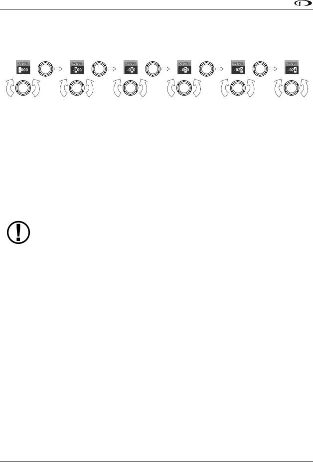
SV-D700, SV-D1000 and SV-D1000T Operation
Joystick and Button Operation Example
Some parameters may need to be adjusted using a joystick. When setting values with the joystick, each character (symbol, letter or digit) must be selected and adjusted successively.
Figure 4–Adjusting Successive Characters with a Joystick
In this example, the first time you turn the joystick, you toggle between the “-” and “+” symbols. To change the succeeding characters, you must move the cursor joystick to the right.
In this example, you first adjust the “-” or “+” character, move the joystick right, then adjust the one hundreds digit, and so forth. Once you have adjusted the value appropriately, press ACCEPT or move the joystick to the right again.
At times, the next item in the menu path in this guide may be a joystick selection OR a button push—the correct choice will be apparent.
Menu Navigation
All menu navigation in this guide starts at the In Flight Setup Menu.
After the display turns on, you will see a screen similar to the one in Figure 1. This guide refers to the label bar at the bottom of the screen as the Main Menu.
Throughout this guide, the “>” character is used to indicate a sequence of menu selections or other actions you would take as you navigate the menu system. Menu selections which are followed by “…” indicate full-screen wizard interfaces which guide you through the appropriate steps. These wizard interfaces are not described in detail in this guide, as the on-screen instructions provide adequate information.
SkyView menus follow this structure: SETUP MENU > MENU > ... > MENU > PAGE or WIZARD. The setup menus (In Flight Setup or Setup) are the root of most menu navigation. Each nested menu is more specific than the previous one and there is no set limit for the number of nested menus before reaching a page. A page or wizard is at the end of the chain and it is where the user can perform a specific action such as create a system software backup, configure a SkyView network, or set up the layout of the onscreen engine gauges. Wizards employ easy-to- follow onscreen instructions.
For example, SETUP MENU > SYSTEM SETUP > MEASUREMENT UNITS > BAROMETER indicates entering the SETUP MENU, then selecting SYSTEM SETUP, then selecting MEASUREMENT UNITS, and then entering the BAROMETER Menu to select INHG, MBAR, or MMHG.
Table 3 is a summary of menu navigation.
3-4 |
SkyView Pilot’s User Guide - Revision S |
 Loading...