


 Loading...
FlightDEK-D180
Combined EFIS and EMS
Pilot’s User Guide
P/N 100601-000, Revision H For use with firmware version 5.4
August, 2010
Dynon Avionics
This product is not approved for installation in type certificated aircraft

Contact Information
Dynon Avionics, Inc.
19825 141st Place NE Woodinville, WA 98072
Phone: (425) 402-0433 - 7:00 AM – 5:00 PM (Pacific Time) Monday - Friday Fax: (425) 984-1751
Dynon Avionics offers online sales, extensive support, and continually-updated information on its products via its Internet sites:
www.dynonavionics.com –Dynon Avionics primary web site; including:
docs.dynonavionics.com – Current and archival documentation.
downloads.dynonavionics.com – Software downloads.
support.dynonavionics.com – Support resources.
store.dynonavionics.com – Dynon’s secure online store for purchasing all Dynon products 24 hours a day.
wiki.dynonavionics.com – Dynon Avionics’ Documentation Wiki provides enhanced, extended, continuously-updated online documentation contributed by Dynon employees and customers.
forum.dynonavionics.com – Dynon Avionics’ Internet forum where Dynon customers can interact and receive Dynon technical support outside of telephone support hours. A key feature of the forum is that it allows the exchange of diagrams, photos, and other types of files.
newsletter.dynonavionics.com – Dynon’s email newsletter.
blog.dynonavionics.com – Dynon’s blog where you can find new and interesting Dynon-related content.
Copyright
2003-2009 Dynon Avionics, Inc. All rights reserved. No part of this manual may be reproduced, copied, transmitted, disseminated or stored in any storage medium, for any purpose without the express written permission of Dynon Avionics. Dynon Avionics hereby grants permission to download a single copy of this manual and of any revision to this manual onto a hard drive or other electronic storage medium to be viewed for personal use, provided that such electronic or printed copy of this manual or revision must contain the complete text of this copyright notice and provided further that any unauthorized commercial distribution of this manual or any revision hereto is strictly prohibited.

Information in this document is subject to change without notice. Dynon Avionics reserves the right to change or improve its products and to make changes in the content without obligation to notify any person or organization of such changes. Visit the Dynon Avionics website (www.dynonavionics.com) for updates and supplemental information concerning the use and operation of this and other Dynon Avionics products.
Limited Warranty
Dynon Avionics warrants this product to be free from defects in materials and workmanship for three years from date of shipment. Dynon Avionics will, at its sole option, repair or replace any components that fail in normal use. Such repairs or replacement will be made at no charge to the customer for parts or labor. The customer is, however, responsible for any transportation cost. This warranty does not cover failures due to abuse, misuse, accident, improper installation or unauthorized alteration or repairs.
THE WARRANTIES AND REMEDIES CONTAINED HEREIN ARE EXCLUSIVE, AND IN LIEU OF ALL OTHER WARRANTIES EXPRESSED OR IMPLIED, INCLUDING ANY LIABILITY ARISING UNDER WARRANTY OF MERCHANTABILITY OR FITNESS FOR A PARTICULAR PURPOSE, STATUTORY OR OTHERWISE. THIS WARRANTY GIVES YOU SPECIFIC LEGAL RIGHTS, WHICH MAY VARY FROM STATE TO STATE.
IN NO EVENT SHALL DYNON AVIONICS BE LIABLE FOR ANY INCIDENTAL, SPECIAL, INDIRECT OR CONSEQUENTIAL DAMAGES, WHETHER RESULTING FROM THE USE, MISUSE OR INABILITY TO USE THIS PRODUCT OR FROM DEFECTS IN THE PRODUCT. SOME STATES DO NOT ALLOW THE EXCLUSION OF INCIDENTAL OR CONSEQUENTIAL DAMAGES, SO THE ABOVE LIMITATIONS MAY NOT APPLY TO YOU.
Dynon Avionics retains the exclusive right to repair or replace the instrument or firmware or offer a full refund of the purchase price at its sole discretion. SUCH REMEDY SHALL BE YOUR SOLE AND EXCLUSIVE REMEDY FOR ANY BREACH OF WARRANTY.
These instruments are not intended for use in type certificated aircraft at this time. Dynon Avionics makes no claim as to the suitability of its products in connection with FAR 91.205.
Dynon Avionics’ products incorporate a variety of precise, calibrated electronics. Except for replacing the optional internal backup battery in EFISbased products per the installation guide, our products do not contain any field/user-serviceable parts. Units that have been found to have been taken apart may not be eligible for repair under warranty. Additionally, once a Dynon Avionics unit is opened up, it will require calibration and verification at our Woodinville, WA offices before it can be considered airworthy.
FlightDEK-D180 Pilot’s User Guide |
iii |

Table of Contents
Contact Information |
..............................................................................................................................................................ii |
Copyright.............................................................................................................................................................................. |
ii |
Limited Warranty ................................................................................................................................................................ |
iii |
1. Introduction |
1-1 |
Before You Fly .................................................................................................................................................................. |
1-1 |
OEM Installations.............................................................................................................................................................. |
1-1 |
Warning ............................................................................................................................................................................. |
1-2 |
About this Guide................................................................................................................................................................ |
1-2 |
2. |
Product Overview |
2-1 |
FlightDEK-D180 Hardware............................................................................................................................................... |
2-1 |
|
ADAHRS Operation.......................................................................................................................................................... |
2-4 |
|
3. |
Product Operation |
3-1 |
Front Panel Layout ............................................................................................................................................................ |
3-1 |
|
Display............................................................................................................................................................................... |
3-2 |
|
Menus ................................................................................................................................................................................ |
3-6 |
|
4. |
Available Pages |
4-1 |
EFIS Main pages ............................................................................................................................................................... |
4-2 |
|
HSI Page............................................................................................................................................................................ |
4-9 |
|
EMS Main Pages ............................................................................................................................................................. |
4-10 |
|
EMS Auxiliary Page........................................................................................................................................................ |
4-11 |
|
|
|
|
FlightDEK-D180 Pilot’s User Guide |
v |
|

Table of Contents
EMS Times Page ............................................................................................................................................................. |
4-12 |
EMS Fuel Computer Page ............................................................................................................................................... |
4-13 |
Lists Pages ....................................................................................................................................................................... |
4-14 |
Menu Pages...................................................................................................................................................................... |
4-14 |
5. EFIS Operation |
5-1 |
POWER – Power on/off ................................................................................................................................................... |
5-1 |
BARO – Changing Altimeter Setting ............................................................................................................................... |
5-1 |
BUGS – Setting Bug Markers .......................................................................................................................................... |
5-2 |
LISTS – Using Checklists and Data Panels...................................................................................................................... |
5-5 |
SETUP – Setting Preferences ........................................................................................................................................... |
5-6 |
INFO – Informational Items ............................................................................................................................................ |
5-10 |
DIM – Changing screen brightness.................................................................................................................................. |
5-13 |
TIMER – Setting and using a timer ................................................................................................................................. |
5-14 |
OATSET – Setting Temperature Offset .......................................................................................................................... |
5-14 |
6. HSI Operation |
6-1 |
Required Connections....................................................................................................................................................... |
6-1 |
Accessing the HSI/DG Page............................................................................................................................................. |
6-1 |
HSI Display Basics ........................................................................................................................................................... |
6-2 |
Navigation Radio Overlay ................................................................................................................................................ |
6-4 |
GPS Overlay ..................................................................................................................................................................... |
6-7 |
HSI Menu Structure.......................................................................................................................................................... |
6-9 |
7. Autopilot Operation |
7-1 |
Introduction and Resources .............................................................................................................................................. |
7-1 |
EFIS AP Indicators........................................................................................................................................................... |
7-2 |
|
|
vi |
FlightDEK-D180 Pilot’s User Guide |

|
|
Table of Contents |
AP Modes .......................................................................................................................................................................... |
7-5 |
|
AP Control Methods.......................................................................................................................................................... |
7-9 |
|
EFIS Autopilot Control ..................................................................................................................................................... |
7-9 |
|
AP74 Autopilot Control................................................................................................................................................... |
7-11 |
|
Disengage/Control Wheel Steering (CWS) Pushbutton .................................................................................................. |
7-15 |
|
Optional Preflight Checklist ............................................................................................................................................ |
7-17 |
|
8. |
Alerts |
8-1 |
Alarm Indicators................................................................................................................................................................ |
8-1 |
|
Multiple Alarms................................................................................................................................................................. |
8-3 |
|
Latching and Self-clearing Alarms .................................................................................................................................... |
8-4 |
|
DSAB Alerts...................................................................................................................................................................... |
8-4 |
|
9. |
EMS Monitoring Functions |
9-1 |
Engine Leaning and Power................................................................................................................................................ |
9-1 |
|
Data Logging ..................................................................................................................................................................... |
9-2 |
|
10. EMS Operation |
10-1 |
|
ON/OFF........................................................................................................................................................................... |
10-1 |
|
Display Brightness (DIM) ............................................................................................................................................... |
10-1 |
|
Fuel Computer ................................................................................................................................................................. |
10-2 |
|
Engine Leaning................................................................................................................................................................ |
10-3 |
|
Clock Setup ..................................................................................................................................................................... |
10-3 |
|
Timers.............................................................................................................................................................................. |
10-4 |
|
Global Configuration Settings ......................................................................................................................................... |
10-5 |
|
11. Appendix |
11-1 |
|
FlightDEK-D180 Pilot’s User Guide |
vii |

Table of Contents
Appendix A: Serial Data Output...................................................................................................................................... |
11-1 |
Appendix B: PC Support Program................................................................................................................................... |
11-6 |
Appendix C: Troubleshooting ......................................................................................................................................... |
11-6 |
Appendix D: FlightDEK-D180 Specifications .............................................................................................................. |
11-11 |
viii |
FlightDEK-D180 Pilot’s User Guide |

1. INTRODUCTION
Thank you for purchasing the Dynon Avionics FlightDEK-D180. This section provides some important cautionary information and general usage instructions for this manual.
Before You Fly
We strongly recommended that you read this entire guide before attempting to use the FlightDEK-D180 in an actual flying situation. Additionally, we encourage you to spend time on the ground familiarizing yourself with the operation of the product. While first learning to use the instrument in the air, we recommend you have a backup pilot with you in the aircraft. Finally, we encourage you to keep this manual in the aircraft with you at all times. This document is designed to give you quick access to information that might be needed in flight. CAUTION: in a flying situation, it is the pilot’s responsibility to use the product and the guide prudently.
OEM Installations
If your FlightDEK-D180 is installed by an OEM distributor, you may find that you are unable to access some menus and settings. Some Dynon distributors customize various areas of the FlightDEK-D180 firmware to maintain a consistent pilot experience and minimize integration issues across a large number of installations. Currently, OEMs can customize access levels to the following settings on Dynon systems: EMS GLOBAL setup menu, EMS SENSOR setup menu, fuel calibration, trim calibration, flaps calibration, GPS/NAV setup menu, screen configurations, data logging, and checklists/data panels. OEM distributors have the option of customizing some or all of these areas. Please contact your aircraft’s manufacturer if you have any questions about how your unit has been customized.
FlightDEK-D180 Pilot’s User Guide |
1-1 |

Introduction
Warning
Dynon Avionics’ products incorporate a variety of precise, calibrated electronics. Except for replacing the optional internal backup battery in EFIS-based products per the installation guide, our products do not contain any field/userserviceable parts. Units that have been found to have been taken apart may not be eligible for repair under warranty. Additionally, once a Dynon Avionics unit is opened up, it will require calibration and verification at our Woodinville, WA offices before it can be considered airworthy.
About this Guide
This guide serves two purposes. The first is to help you configure and get acquainted with the FlightDEK-D180‘s many functions. The second is to give you quick access to vital information. For detailed technical and installation information, please refer to the FlightDEK-D180 Installation Guide.
In the electronic (.PDF) version of this manual, page and section references in the Table of Contents and elsewhere act as hyperlinks taking you to the relevant location in the manual. The latest version of this manual may be downloaded from our website at docs.dynonavionics.com.
This guide discusses the most common operation scenarios. If you have an operational issue that is not discussed in this guide, you can find additional operational information on Dynon’s Internet sites:
wiki.dynonavionics.com – Dynon’s Documentation Wiki provides enhanced, extended, frequently updated online documentation contributed by Dynon employees and customers.
forum.dynonavionics.com – Dynon’s Online Customer Forum is a resource for Dynon Avionics customers to discuss installation and operational issues relating to Dynon Avionics products. The Forum is especially useful for pilots with uncommon aircraft or unusual installation issues. For customers that cannot call Dynon Technical Support during our normal business hours, the Forum is a convenient way to interact with Dynon Avionics Technical Support. The Forum allows online sharing of wiring diagrams, photos, and other types of electronic files.
1-2 |
FlightDEK-D180 Pilot’s User Guide |

Introduction
The following icons are used in this guide:
Any text following this icon describes functionality available only with the HS34 HSI Expansion Module connected to your system.
Any text following this icon describes functionality available only with the AP74 Autopilot Interface Module connected to your system.
Any text following this icon describes functionality that is possible when multiple Dynon Avionics products are networked together via the Dynon Smart Avionics Bus (DSAB).
Any text following this icon refers to a setting or situation which merits particularly close attention.
FlightDEK-D180 Pilot’s User Guide |
1-3 |
2. PRODUCT OVERVIEW
This section provides a general overview of the various parts of the FlightDEK-D180 as well as a theory of operation. The information in this section serves as a reference only and helps familiarize you with the inner workings of the unit. It should not be used for diagnostic or reparative work.
FlightDEK-D180 Hardware
The FlightDEK-D180‘s versatile design accommodates a wide range of engines and sensors. You may configure the system to meet your monitoring requirements covering both airand water-cooled engines with up to six cylinders. Its warning capabilities provide early notification of problems that might otherwise go unnoticed. The FlightDEK-D180 uses solid-state sensors to provide accurate and reliable information about your flying environment in an easy-to-use interface.
POWER
The FlightDEK-D180 requires between 10 and 30 volts DC for operation and has inputs for an external backup power supply and a keep-alive voltage. It is acceptable to have the FlightDEK-D180 turned on during engine start.
The FlightDEK-D180 can be ordered with an optional internal battery which allows the instrument to continue to operate in the event of an external power failure. This lithium-ion battery is rechargeable and is managed by the FlightDEKD180. If the always-on Keep Alive circuit is connected, the FlightDEK-D180 continues to charge its internal battery even if the instrument is turned off. This ensures that your internal emergency battery is always fully charged. Under normal conditions, the internal battery should have a voltage between 13 and 16.8 volts. When the battery’s voltage drops below 13 volts, the FlightDEK-D180 displays a low battery warning. When new, a fully charged internal battery is rated for a minimum of 1.5 hours of normal operation with the FlightDEK-D180. If the FlightDEK-D180 has switched to its internal emergency battery due to a power loss in your aircraft, it is advised that you land as soon as possible.
FlightDEK-D180 Pilot’s User Guide |
2-1 |

Product Overview
SENSORS AND INPUTS
Attitude information is obtained from 3 solid-state gyrometers, 3 solid-state accelerometers, and the airspeed pressure sensor. Heading information is obtained from 3 solid-state magnetometers housed in the EDC-D10A. Airspeed, altitude and angle of attack are obtained from three separate pressure transducers.
HSI information can be displayed when connected to Dynon’s HS34, a Garmin SL30, or a compatible GPS unit.
When connected to the appropriate sensors, the FlightDEK-D180 displays RPM, manifold pressure, oil temperature and pressure, exhaust gas temperature (EGT), cylinder head temperature (CHT), fuel levels for up to 4 tanks, voltage, current, fuel pressure, fuel flow, carburetor air temperature, coolant pressure and temperature, outside air temperature, flaps, trim, and the status of up to two external contacts. Fuel endurance and economy information can be obtained when a compatible GPS unit is connected to your system.
DYNON SMART AVIONICS BUS
If you have multiple Dynon Avionics products in your aircraft, they may be networked together via the Dynon Smart Avionics Bus (DSAB). Units networked via DSAB have the ability to transmit information to each other. Any product’s data can then be viewed on any other screen in the DSAB network. For example, an EFIS has the ability to display engine monitor information if it is connected to an EMS or FlightDEK-D180.
Note that the failure of a unit in a DSAB network may cause the loss of some or all data shared between units. In the above example, if the connected EMS/FlightDEK-D180 were to fail, the EFIS would no longer be able to behave as an engine monitor. For more information on DSAB-specific alerts, refer to the DSAB Alerts section on page 8-4.
OUTPUTS
The FlightDEK-D180 has outputs to drive external customer-supplied audible and visual devices for engine, AOA (if installed) and altitude alerts.
2-2 |
FlightDEK-D180 Pilot’s User Guide |

Product Overview
A serial output is also provided for serial altitude encoder data. An optional Serial-to-Gray Code Converter is available for connection to Mode C Gray Code transponders.
A connected HS34 or AP74 can output voice annunciations for many of the alerts generated by the FlightDEKD180.
DISPLAY
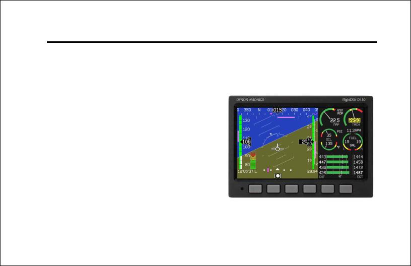
The display is a 7-inch, 854 by 480 pixel, 400 nit or 800 nit LCD screen, depending on the model.
BUTTONS AND KNOBS
User interaction takes place via the six buttons along the bottom of the front panel of the unit.
When an AP74 Autopilot Interface Module is configured to control the FlightDEK-D180, its VALUE knob changes values when in various EFIS menus. When no menus are displayed the AP74 can adjust the barometer, altitude bug, and heading bug. The AP74’s buttons control the Autopilot operation mode (Heading Hold, Track Hold, GPS horizontal navigation, altitude hold), and allow you to engage and disengage the Autopilot.
When an HS34 is configured to control the FlightDEK-D180, its VALUE knob changes values when in various EFIS menus. When no menus are displayed the HS34 can adjust the barometer or altitude bug. The HS34’s HEADING and COURSE knobs affect their respective parameters on the HSI page. The HS34’s GPS and NAV buttons cycle through the available GPS and NAV sources connected to it.
FlightDEK-D180 Pilot’s User Guide |
2-3 |

Product Overview
ADAHRS Operation
The primary flight instruments on your EFIS display are generated using a group of calibrated sensors. All of them are solid state – that is, there are no moving parts. These sensors include accelerometers, which measure forces in all three directions; rotational rate sensors, which sense rotation about all three axes; pressure transducers for measuring air data; and magnetometers on all three axes for measuring magnetic heading. These sensors form the core of Dynon’s Air Data Attitude and Heading Reference System (ADAHRS).
The table below describes which inputs and sensors are used within the EFIS to generate the different displayed instruments. It is not meant to enable in-flight troubleshooting, but is provided to convey how much of an integrated system your EFIS is.
|
GPS |
Pitot |
Static |
AOA |
Magnetometers |
Rate Sensors |
Accelerometers |
Ball |
|
|
|
|
|
|
X |
Altitude |
|
|
X |
|
|
|
|
Airspeed |
|
X |
X |
|
|
|
|
AOA |
|
X |
X |
X |
|
|
|
Turn Rate |
X* |
X |
X |
|
|
X |
X |
Heading |
X* |
X |
X |
|
X |
X |
X |
Attitude |
X* |
X* |
X |
|
|
X |
X |
ATTITUDE CALCULATION
The FlightDEK-D180 artificial horizon display (attitude) is generated via a complex algorithm using a multitude of sensors. Your EFIS attitude is not reliant on any single external system. It can provide an accurate attitude - even in the event of airspeed loss (due to icing or other blockage) - via a redundant GPS aiding source. In normal operation the
2-4 |
FlightDEK-D180 Pilot’s User Guide |
Product Overview
instrument uses airspeed to provide superior attitude accuracy. If a problem develops with your airspeed reading, a properly connected and configured GPS source acts as a substitute.
When in this mode the instrument continues to provide accurate attitude.
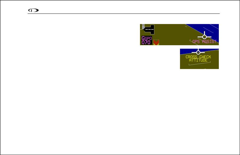
*If a GPS is present upon the loss of airspeed, the FlightDEK-D180 uses the GPS ground speed in its attitude calculation. When in this
mode, a magenta GPS ASSIST message is displayed over the horizon and the ground speed is displayed below the IAS indicator (as shown at right). If the connectivity with the GPS fails while in GPS assist mode, the attitude continues to be displayed, using the last known GPS ground speed as a reference. This mode is flagged on the horizon with a yellow CROSS CHECK ATTITUDE message. In the very rare case that this sequence of event occurs, the FlightDEK-D180’s attitude accuracy is reduced; use other references in the aircraft to crosscheck against the FlightDEK-D180’s attitude.
COMPASS ACCURACY AND AUTOPILOT PERFORMANCE
If you are using your FlightDEK-D180 to control Dynon’s Autopilot, it is critical that the magnetic heading be as accurate as possible for comfortable operation in HDG mode and radio-based VOR/NAV mode. The aircraft’s compass must be installed correctly, calibrated, and operating well in all attitudes.
FlightDEK-D180 Pilot’s User Guide |
2-5 |
3. PRODUCT OPERATION
After reading this section, you will be familiar with the basics of how to use your FlightDEK-D180. For details regarding specific procedures (e.g., adjusting display brightness, using the fuel computer, setting the clock, etc.) please refer to the EFIS Operation and EMS Operation sections.
Front Panel Layout
All normal operation of the FlightDEK-D180 happens via the front panel. The front panel contains buttons and a display.
Buttons – There are six buttons on the front panel of the FlightDEK-D180. Throughout this guide, these buttons are referred to as one through six, with button one being the leftmost and button six being the rightmost. FlightDEKD180 buttons are used to turn the instrument on and off, cycle between screens, scroll through menus, and adjust instrument parameters.
Display – The display shows EFIS information and engine parameters, menus, and data obtained from other connected
products. |
1 |
2 |
3 |
4 |
5 |
6 |
User interaction takes place via the FlightDEK-D180 main display and the six buttons beneath. Note: buttons are not labeled on actual product
FlightDEK-D180 Pilot’s User Guide |
3-1 |

Product Operation
Display
The FlightDEK-D180 display is the most obvious and commonly used output of the device. It is capable of displaying EFIS, HSI, and/or engine data simultaneously.
SCREENS AND PAGES
The terms in the following bulleted list are used in this section and are defined as follows:
Screen/Screen Configuration – Screens consist of one or two pages from the FlightDEK-D180 or from another DSAB-connected Dynon Avionics product.
Page – A page is a section of the screen that contains a collection of related data. Pages may occupy the total area of the screen (i.e., 100%) or share the screen with other pages (e.g., 2/3, 1/3 split). Pages that occupy 1/3 of the screen area are sometimes abbreviated versions of their full size (100% or 2/3) counterparts.
Screen Rotation – The rotation is the list of screen configurations which can be cycled to via the hotkeys. Your rotation is usually smaller than the total list of available screen configurations.
Screens contain one or two pages and pages contain groups of similar information.
3-2 |
FlightDEK-D180 Pilot’s User Guide |

Product Operation
The FlightDEK-D180 has several pre-defined screen configurations. The basic layout of a screen configuration is represented by one of three icons on D100-series product. The table at right shows the three icons and their meaning.
The predefined screen configurations with their respective icons are as follows:
Icon |
Left Page Area |
|
Right Page Area |
|
2/3 |
|
1/3 |
|
1/3 |
|
2/3 |
|
|
|
|
|
One page that occupies all of the screen |
||
|
|
area |
|
The SCREEN LIST Menu uses icons to illustrate the layout for each screen configuration.
 EFIS/EMS (default FlightDEK-D180 boot-up screen; in default rotation)
 EFIS/AUX (in default screen rotation)
 EFIS/FUEL (in default screen rotation)
 EFIS/TIMES (in default screen rotation)
 EFIS/HSI (in default screen rotation)
 EMS/EFIS
 EMS/AUX
 EMS/TIMES
 EMS/FUEL
 EMS/HSI
 EFIS
EFIS
 EFIS/EMS
 EMS/EFIS
 HSI/EMS
FlightDEK-D180 Pilot’s User Guide |
3-3 |
Product Operation
CYCLING BETWEEN SCREENS
There are two methods for cycling between pre-defined screens: via the menu and via hotkeys.
Screen Cycling Using the SCREEN LIST
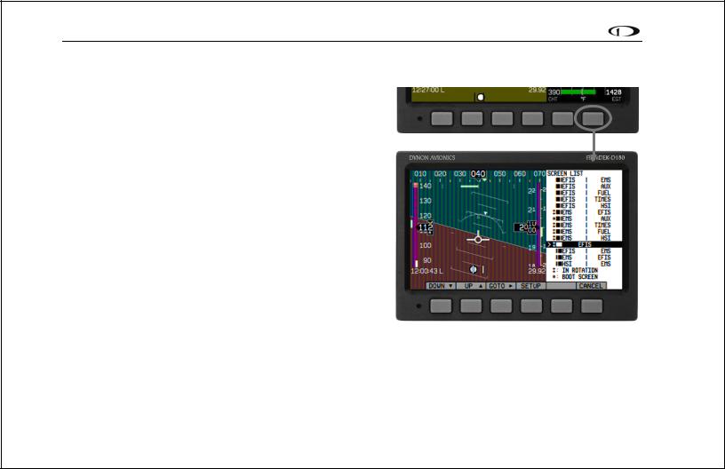
Navigate to the SCREEN LIST menu by holding button six for at least two seconds when no menu is present (see the figure to the right). Note that if you only press button six momentarily, the display cycles to the next screen in your screen rotation. Use the DOWN▼/UP▲ buttons to move the caret (>). The caret denotes the selected screen. Press GOTO► to remove the SCREEN LIST and display the selected screen. If you wish to stay on the same screen, you may either select your currently displayed screen with the caret and press GOTO►, or press CANCEL.
Screen Cycling Using Hotkeys
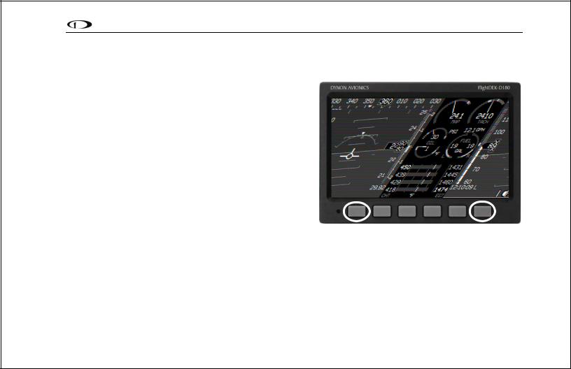
With no menu displayed, press button one to cycle to the previous screen in your rotation. Likewise, press button six to cycle to the next screen in your rotation (see the figure on the next page). Cycling via hotkeys only allows you to display screens that are in your screen rotation. They are meant to give you quick access to the screen configurations that are most important to you. If you wish to access screens that are not in your rotation, use the SCREEN LIST as described above.
Hold two seconds
With no menus displayed, pressing button six for two seconds displays the SCREEN LIST menu, from which you may switch to, and set up, various screen configurations.
3-4 |
FlightDEK-D180 Pilot’s User Guide |
Product Operation
Changing the Screen Rotation
You may use the out-of-the-box screen rotation or define your own. If you desire to use the initial rotation, no user configuration is required. If you desire to use a custom cycling
order, then user configuration is necessary.
To configure a custom rotation, navigate to the SCREEN LIST menu page by pressing button six for approximately two seconds when no menu is present. Press SETUP, then press ROTATN to display the menu used to change the boot and rotation screen. Scroll through the pre-defined screens using the DOWN▼/UP▲ buttons.
Press the BOOT* button on any selected screen configuration to make it the screen that is shown immediately after the instrument is turned on. Only one screen may be designated as the boot screen. Next, press the TOGGL↕ button on any selected screen to toggle the “↕” icon. All screens that show the “↕” icon are included in the rotation. Any screen in the rotation may be accessed via the button one and six hotkeys. Press BACK to save any settings.
cycles to |
|
cycles to |
prev. screen |
|
next screen |
|
|
|
Buttons one and six cycle to the previous and next screens, respectively.
Changing the Screen List Order
You may wish to change the order in which screen configurations are displayed in the SCREEN LIST, thus changing the order they are cycled to via hotkeys. To do this, navigate to the SCREEN LIST menu page by pressing button six for approximately two seconds when no menu is present. Press SETUP, then press ORDER to display the menu used to change the screen order. Scroll through the pre-defined screens using the DOWN▼/UP▲ buttons. Press the MV DN▼
FlightDEK-D180 Pilot’s User Guide |
3-5 |
button to move the selected screen down in the screen list. Likewise, press the MV UP▲ button to move the selected screen up in the screen list.
Menus
All interaction with the FlightDEK-D180 is accomplished through the use of its menu system. The menu system is accessed and navigated via the six buttons located on the front of the unit.
PAGE-SENSITIVE MENUS
On a screen where no menu is already present, buttons two through five are used to display a menu. With no menu displayed, pressing any one of these buttons causes the menu for the page above it to show at the bottom of the screen. For example, if a screen is divided into two pages with the left page occupying 2/3 of the screen and the right page occupying 1/3 of the screen, then pressing FlightDEK-D180 buttons two, three, or four (all below the left 2/3 of the screen) displays the main menu for the left page and pressing button five (below the right 1/3 of the screen) displays the main menu for the right page (see the figure to the right).
FUNCTIONALITY
A menu consists of two rows of gray boxes containing text. The upper row contains one tab that denotes the currently displayed menu. The lower row contains six labels that denote the function of the button below it. Many of the onscreen elements move up to avoid the menu. This prevents the menu from obscuring useful data while it is up. Upon exiting the menu, the screen returns to its normal appearance.
Pressing a button either displays another menu or adjusts a parameter. If there is no
The configuration of the pages on the screen determines which buttons are used to display a page’s menu.
3-6 |
FlightDEK-D180 Pilot’s User Guide |
text above a button, then that button does not have a function in the context of that menu. Occasionally, a button label spans two or more buttons. In this case, any button below the label invokes the command.
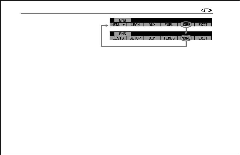
If a menu contains more options than there are buttons, the MORE label is displayed over button five. Pressing this button shows you the next set of options in the current menu.
In any menu, press the BACK button to return to the previous menu and save any changes. In all top-level menus, button six is the EXIT button. Pressing EXIT removes the menu system and moves many of the onscreen elements down to their original positions.
FLOW
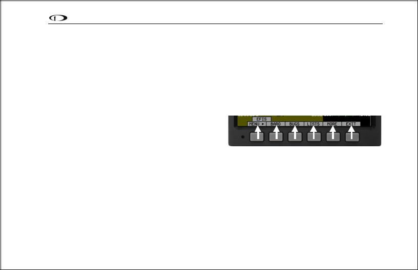
Each page has its own main menu, which may contain options for navigating to other menus or choosing and adjusting parameters. For example, the EFIS Main Page menu contains an EFIS menu tab and button labels for MENU►, BARO, BUGS, LISTS, MORE, and EXIT. Pressing MORE reveals the rest of the EFIS menu. This menu contains options for SETUP, INFO, DIM, TIMER, MORE, and EXIT. Pressing MORE on this menu simply returns you to the first part of the EFIS menu.
Each menu consists of labels above each button denoting their function.
In all top-level page menus (EFIS, EMS, AUX, TIMES, FUEL, and HSI), the leftmost button is the MENU button. If you have opened up the left page’s menu, the label reads MENU►. Pressing the button switches the menu to display the right page’s menu, and the label switches to read ◄MENU. The arrow on this button always points to the side of the screen whose menu is displayed when pressing the button.
FlightDEK-D180 Pilot’s User Guide |
3-7 |
Product Operation
All EMS 1/3 pages (AUX, TIMES, FUEL) have shortcuts to their page and menu from within the EMS Main Page menu. This means that if you only want to glance at a parameter on another page, quickly returning to your original screen configuration, simply enter the EMS menu, and press the button for the page you’d like to momentarily view. For example, if your current screen configuration is 2/3 EMS on the left, 1/3 FUEL on the right, pressing the AUX
button in the EMS menu displays the AUX page in place of the FUEL page and the AUX page menu. Pressing BACK returns you to the main EMS menu, and your original screen configuration (i.e., EMS/FUEL).
If you press the SETUP button on the EMS menu, the SETUP menu is displayed. The SETUP menu contains a menu tab and button labels for CLOCK, VRSION, GLOBAL, SENSOR, FUEL, and BACK. Pressing CLOCK displays options for specifying time format (i.e., standard AM/PM vs. military) and clock adjustment.
To exit the menu system, press the BACK button as many times as is needed to reach an EXIT button. This varies based upon how deep you are into the menu system.
DESCRIPTIONS IN THIS GUIDE
Throughout this guide, the “>“ character is used to indicate entering a deeper level of the menu system. For example, “EFIS > INFO > LEFT” indicates entering the EFIS menu, pressing MORE, then pressing INFO, and then pressing LEFT to enter the left info item menu. Note that the MORE button is not included in the sequence, since pressing MORE reveals more options in the same level of the menu system.
3-8 |
FlightDEK-D180 Pilot’s User Guide |

4. AVAILABLE PAGES
The EFIS main pages use various tapes, digital displays, and other indicators overlaid on an artificial horizon. On the 2/3 and full-screen pages, you may also display up to two “info items” on the left and right side of the main page. HSI pages use text and a DG style compass by itself or overlaid with lines and arrows of different colors.
Note: HSI pages use data that is obtained from a source external to the FlightDEK-D180. Refer to the FlightDEKD180 Installation Guide for a list of compatible equipment.
The EMS pages use various combinations of circular gauges, vertical and horizontal bars, tic marks, and text to display EMS data. Appropriate units of measurement accompany their respective values. Color indicators (green, yellow, and red) are used to denote normal and abnormal operational ranges.
Both the EMS Main Pages and the EMS Auxiliary Page allow for “info items,” user-configurable elements such as vertical info bars, contact input readouts, flaps/trim indication, and text-only items. Vertical info bars can display volts, amps, fuel pressure, carburetor air temperature, coolant temp/pressure, and outside air temperature. Contact input readouts can display discrete data (e.g., open/closed, on/off, etc.). Flaps and trim displays display icons indicating the absolute position of the flaps and trim. Vertical info bars, contacts, flaps/trim indicators, and text-only items are defined at time of installation and instrument setup. Text info items include fuel economy, engine timers, and times. For more information on configuring this display (as well as info items on the EMS Main Page), see the Info Item Configuration section on page 10-6. Menu, Checklist, and EFIS pages may be displayed and are described in the following sections.
FlightDEK-D180 Pilot’s User Guide |
4-1 |

Available Pages
EFIS Main pages
Available in 1/3, 2/3 and full formats
The FlightDEK-D180 default screen rotation includes only 2/3 EFIS pages combined with the various EMS and HSI pages described below. However, you may also choose screen configurations that use 1/3 and full-screen pages. The 2/3 and full-screen pages can display EFISand EMS-related info items on the left and right side of the screen. You can enable any of the non-default EFIS screens as described in the Changing the Screen Rotation section on page 3-5. Some of the displayed items described below may not be onscreen, depending on whether or not they have been enabled in the CLUTTR menu.
Beginning with firmware revision 3.0, Dynon adopted a dramatically different EFIS display format than it had previously used. If your EFIS display does not resemble the layouts shown at right, first ensure that you are using firmware version 3.0 or higher. Then, ensure that the setting at EFIS > SETUP > STYLE is set to MODERN. If you prefer the previous display style, you can change this setting to CLASSIC. The classic display format is documented in previous revisions of this manual, available on Dynon Avionics’ website at docs.dynonavionics.com. No further development will occur on the classic display format.
The following sub-sections describe the displayed items in detail.
4-2 |
FlightDEK-D180 Pilot’s User Guide |

Available Pages
Horizon line, pitch and roll indicators
Bounded on the top by blue, and on the bottom by brown, the horizon line behaves in much the same way as a traditional gyro-based artificial horizon. Unlike a mechanical artificial horizon, the FlightDEK-D180‘s horizon has no roll or pitch limitation. The horizon line stays parallel to the Earth’s horizon line regardless of attitude. The parallel lines above and below the horizon line are the pitch indicator lines, with each line indicating 5 degrees of pitch. The end of each 10º pitch indicator line has a hooked barb that points towards the horizon line to aid attitude awareness.
The roll scale has tic marks at 10, 20, 30, 45, 60, and 90 degrees of roll. In the CLUTTR menu
(described on page 5-7), you can choose between a stationary roll indicator and one that rotates along with the horizon. The stationary roll indicator (type 1 in the EFIS > SETUP > CLUTTR > ROLL menu) has an internal arrow which moves to stay perpendicular to the horizon, like a jet EFIS presentation. The moving roll indicator (type 2) rotates the scale about a stationary internal arrow which points to the current roll angle on the scale, like most mechanical attitude instrument presentations.
Please see the ADAHRS Operation section on page 2-4 for important information about the theory of operation for the attitude and external data sources.
CDI/Glideslope Indicators
When the FlightDEK-D180 is receiving CDI or glideslope information from a GPS or NAV radio, they can be displayed on the main EFIS display as well as the on the full HSI page (as described in the HSI Operation section on page 6-1). The data source is chosen on the HSI page using the NAVSRC button; the EFIS and HSI CDI/GS displays are always synchronized to the same source. There is no way to change the source on the EFIS screen.
On the EFIS page, these two items are enabled via the EFIS > SETUP > CLUTTR menu under a single item, which can be set to either CDI:N, CDI:Y, or CDI+GS.
FlightDEK-D180 Pilot’s User Guide |
4-3 |
Available Pages
The CDI is located just above the slip/skid ball when displayed, and behaves much as described in the HSI Operation section on page 6-1. The CDI needle is green when sourced from a NAV radio and magenta when sourced from GPS. When to/from information is available, the center of the CDI is an arrow; when on an ILS, it is a filled-in square.
The glideslope indicator is located to the left of the roll scale tape, and behaves much as described in the HSI Operation section on page 6-1. The GS needle is green when sourced from a NAV radio and magenta when sourced from GPS, and appears only when tuned to an ILS or a GPS source with vertical guidance.
Due to screen space limitations, turning on the glideslope prevents a left info item from being displayed on the 2/3- screen EFIS page. Additionally, at extreme roll angles, the glideslope is hidden to provide space for other screen elements.
Stabilized heading tape and digital readout
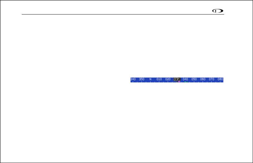
Located at the top of the EFIS page, the heading indicator functions much like a standard slaved directional gyro. North,
East, South, and West directions are labeled on the tape, “N,” “E,” “S,” and “W,” respectively. The digital readout displays your current heading, while the surrounding tape scrolls beneath its arrow. You may set a yellow bug on this tape as a heading reminder. The pointer in the digital readout is hollow to allow the GPS ground track indicator, displayed as a magenta arrow, to show through. A difference between the ground track arrow and the current heading indicates that some wind is present. The currently set course heading is represented by a “V,” colored green when sourced from a NAV radio and magenta when sourced from GPS. When the CDI is centered, aligning the ground track pointer within the course pointer compensates for all wind and takes you directly to the waypoint or VOR. For course and ground track to be displayed on the heading tape, they must both be enabled in the CLUTTR menu.
Like a conventional gyro-stabilized magnetic compass, magnetic heading reacts immediately to turn rate so that heading changes are reflected immediately. It then uses magnetometer data over the long term to ensure that it remains correct. Additionally, heading is corrected for attitude so that it is accurate as you pitch and roll.
4-4 |
FlightDEK-D180 Pilot’s User Guide |

Available Pages
Turn rate indicator
Centered just below the heading digital readout, the turn rate indicator displays the aircraft’s current rate of turn with respect to the ground. The magenta bar grows in the direction that the aircraft is currently turning, and is anchored at a white vertical anchor line. The brackets on either side of the bar’s anchor line
represent the turn rate which results in a standard rate turn. Turn rate takes attitude into account. This means that even when you are highly banked, it still shows rate of turn in relation to the aircraft’s heading.
The turn rate indicator is scaled to indicate a 6-second heading trend. In the example above, the trend indicator is showing that the aircraft will be pointed at 17º in 6 seconds if the rate of turn does not change.
Altitude tape, digital readout, and VSI
The altitude tape scrolls beneath the altitude digital readout and arrow. The digital readout’s digits scroll up and down, simulating an analog altimeter and giving a sense of the direction of movement. Thousands of feet are displayed using large numbers while hundreds of feet are displayed in smaller numbers. The FlightDEK-D180 accurately displays altitudes from -1200 to 30,000 ft (-365 to 9144 m).
The graphical Vertical Speed Indicator is located next to the altitude tape. The magenta bar grows in the direction of – and in proportion to – the rate of climb or descent. The numbers on the scale represent thousands of feet per minute. In the CLUTTR menu, the VSI scale can be set to display 1000 ft/min, 2000 ft/min, and 4000 ft/min. The 2000 ft/min scale is linear throughout the range, while the 1000 ft/min and 4000 ft/min are non-linear as shown on the scale. When set to display 2000 ft/min, the VSI bar is scaled to indicate a 6-second altitude trend based on its position with relation to the altitude bar. When set to display 4000 ft/min, the VSI bar is scaled to indicate a 6-second trend only up to 1000 ft/min. When set to display 1000 ft/min, the VSI bar is scaled to indicate a 12-second trend up to 500 ft/min.
FlightDEK-D180 Pilot’s User Guide |
4-5 |

Available Pages
During the first 30 seconds of operation, the altitude tape and digital readout are not displayed as the unit needs a small amount of time before altitude measurements are deemed accurate.
Elevator trim indicator
Located in the lower right corner of the EFIS page, the elevator trim indicator displays the relative trim of the elevator in graphic form. The elevator trim indicator can only be displayed on the FlightDEK-D180 if an elevator trim sensor is properly connected to one of the 3 EMS GP inputs, and is properly configured in the EMS setup. As with the EMS info item, the green line indicates takeoff trim. The two arrows indicate the current elevator trim.
Winds aloft arrow
Located in the lower right corner of the EFIS page, the winds aloft arrow indicates the wind direction relative to your current direction of flight. The number indicates the current absolute wind speed in the current airspeed units. If the FlightDEK-D180 cannot make an accurate winds aloft calculation, the arrow is not displayed and the numbers are replaced by dashes. The display of winds aloft requires an active GPS connection and an OAT probe. In very light winds, the wind speed number is not displayed, although the arrow is.
Angle of attack (AOA) indicator
The angle of attack indicator – available only with Dynon’s AOA Pitot Probe – displays the aircraft’s current AOA relative to the stall AOA. The AOA calibration process should result in the lowest angle of attack stall (usually the “clean” configuration) occurring between the yellow and red lines and the higher angle-of-attack stall (usually the “dirty” configuration) occurring at the top of the red. As your aircraft’s angle of attack increases, the bars in the indicator disappear, leaving the empty outline. As your aircraft’s AOA approaches stall, downward-pointing arrows are left. Depending on your installation and configuration, an audible alarm may also occur when near or in the stall. This audio alarm is accompanied by a flashing red triangle at the top of
4-6 |
FlightDEK-D180 Pilot’s User Guide |

Available Pages
the AOA display. To judge when a stall will occur, remember that the AOA indicator is showing actual AOA, and the stall AOA changes with configuration. Because of this, a stall could occur anywhere inside the yellow range, but will occur at the same point every time given a specific configuration. Refer to the FlightDEK-D180 Installation Guide for more information on calibrating the AOA indicator.
Airspeed tape, digital readout, and trend
The airspeed tape scrolls beneath the airspeed digital readout and arrow. The digital readout’s digits scroll up and down, simulating an analog airspeed indicator and giving a sense of the increase or decrease in speed. The FlightDEK-D180 is factory-calibrated to be accurate for airspeeds between 15 and 325 knots (17 to 374 mph). As airspeed increases from 0 knots, the indicator becomes active at 20 knots. The indicator remains active until airspeed drops below 15 knots. The FlightDEK-D180 may display airspeeds above 325 knots, but it is not guaranteed to be accurate.
The airspeed tape utilizes 4 colors to give you a graphical representation of your speed with relation to your aircraft’s limits. By default all of the color thresholds are set at 0, causing a grey tape to be displayed. You must set the values of the airspeed color thresholds via the SETUP menu. Refer to the FlightDEK-D180 Installation Guide for more information on setting the airspeed color thresholds.
The airspeed trend indicator is located to the left of the airspeed tape. The magenta bar grows in the direction of—and in proportion to—the rate of acceleration or deceleration. The trend indicator is scaled to indicate a 6-second airspeed trend. In the example at right, the trend indicator is showing that the aircraft will reach 124 knots in 6 seconds if the rate of acceleration does not change.
Bugs
Bugs may be set to mark a desired heading, airspeed, or altitude. These bugs are represented by a yellow inverted arrow located at the desired value on the tape. If the set heading, altitude, or airspeed is currently off-screen, the bug icon appears at the edge of the moving tape closest to the desired value.
FlightDEK-D180 Pilot’s User Guide |
4-7 |
Loading...