


EFIS-D6
Table of contents
 Loading...
EFIS-D6
Installation Guide
This product is not approved for installation in type certificated aircraft.
P/N 101209-000, Revision A
For use with firmware version 1.0
May, 2009
Copyright © 2003-2009 by Dynon Avionics, Inc.


Contact Information
Dynon Avionics, Inc.
19825 141
Woodinville, WA 98072
Phone: (425) 402-0433 - 7:00 AM – 5:00 PM (Pacific Time) Monday - Friday
Fax: (425) 984-1751
Dynon Avionics offers online sales, extensive support, and continually-updated information on its products via its Internet sites:
st
Place NE
www.dynonavionics.com
docs.dynonavionics.com
downloads.dynonavionics.com
support.dynonavionics.com
store.dynonavionics.com
wiki.dynonavionics.com
documentation contributed by Dynon employees and customers.
forum.dynonavionics.com
outside of telephone support hours. A key feature of the forum is that it allows the exchange of diagrams, photos, and other types of
files.
newsletter.dynonavionics.com
blog.dynonavionics.com
–Dynon Avionics primary web site; including:
– Current and archival documentation.
– Software downloads.
– Support resources.
– Dynon’s secure online store for purchasing all Dynon products 24 hours a day.
– Dynon Avionics’ Documentation Wiki provides enhanced, extended, continuously-updated online
– Dynon Avionics’ Internet forum where Dynon customers can interact and receive Dynon technical support
– Dynon’s email newsletter.
– Dynon’s blog where you can find new and interesting Dynon-related content.
Copyright
© 2003-2009 Dynon Avionics, Inc. All rights reserved. No part of this manual may be reproduced, copied, transmitted, disseminated or stored in
any storage medium, for any purpose without the express written permission of Dynon Avionics. Dynon Avionics hereby grants permission to
download a single copy of this manual and of any revision to this manual onto a hard drive or other electronic storage medium to be viewed for
personal use, provided that such electronic or printed copy of this manual or revision must contain the complete text of this copyright notice and
provided further that any unauthorized commercial distribution of this manual or any revision hereto is strictly prohibited.
Information in this document is subject to change without notice. Dynon Avionics reserves the right to change or improve its products and to
make changes in the content without obligation to notify any person or organization of such changes. Visit the Dynon Avionics website
(www.dynonavionics.com
products.
) for current updates and supplemental information concerning the use and operation of this and other Dynon Avionics
Limited Warranty
Dynon Avionics warrants this product to be free from defects in materials and workmanship for three years from date of shipment. Dynon
Avionics will, at its sole option, repair or replace any components that fail in normal use. Such repairs or replacement will be made at no charge
to the customer for parts or labor. The customer is, however, responsible for any transportation cost. This warranty does not cover failures due to
abuse, misuse, accident, improper installation or unauthorized alteration or repairs.
THE WARRANTIES AND REMEDIES CONTAINED HEREIN ARE EXCLUSIVE, AND IN LIEU OF ALL OTHER WARRANTIES
EXPRESSED OR IMPLIED, INCLUDING ANY LIABILITY ARISING UNDER WARRANTY OF MERCHANTABILITY OR FITNESS
FOR A PARTICULAR PURPOSE, STATUTORY OR OTHERWISE. THIS WARRANTY GIVES YOU SPECIFIC LEGAL RIGHTS, WHICH
MAY VARY FROM STATE TO STATE.
IN NO EVENT SHALL DYNON AVIONICS BE LIABLE FOR ANY INCIDENTAL, SPECIAL, INDIRECT OR CONSEQUENTIAL
DAMAGES, WHETHER RESULTING FROM THE USE, MISUSE OR INABILITY TO USE THIS PRODUCT OR FROM DEFECTS IN
THE PRODUCT. SOME STATES DO NOT ALLOW THE EXCLUSION OF INCIDENTAL OR CONSEQUENTIAL DAMAGES, SO THE
ABOVE LIMITATIONS MAY NOT APPLY TO YOU.
Dynon Avionics retains the exclusive right to repair or replace the instrument or firmware or offer a full refund of the purchase price at its sole
discretion. SUCH REMEDY SHALL BE YOUR SOLE AND EXCLUSIVE REMEDY FOR ANY BREACH OF WARRANTY.
These instruments are not intended for use in type certificated aircraft at this time. Dynon Avionics makes no claim as to the suitability of its
products in connection with FAR 91.205.
Dynon Avionics’ products incorporate a variety of precise, calibrated electronics. Except for replacing the optional internal backup battery in
EFIS-based products per the installation guide, our products do not contain any field/user-serviceable parts. Units that have been found to have
been taken apart may not be eligible for repair under warranty. Additionally, once a Dynon Avionics unit is opened up, it will require calibration
and verification at our Woodinville, WA offices before it can be considered airworthy.


Table of Contents
Contact Information......................................................................................................................................................iii
Copyright......................................................................................................................................................................iii
Limited Warranty .........................................................................................................................................................iii
1. Introduction 1-1
Warning ..................................................................................................................................................................... 1-1
About this Guide........................................................................................................................................................ 1-2
Menu Descriptions..................................................................................................................................................... 1-2
2. Wiring Overview 2-1
Recommended Wiring Practices................................................................................................................................2-1
Power Requirements.................................................................................................................................................. 2-1
25-Pin Female EFIS Harness..................................................................................................................................... 2-2
3. Instrument Installation 3-1
Selecting a Remote Compass Module Location ........................................................................................................ 3-1
EDC-D10A Communication Cable ........................................................................................................................... 3-2
Power Inputs.............................................................................................................................................................. 3-3
EFIS Serial Harness................................................................................................................................................... 3-3
Altitude Encoder Wiring ........................................................................................................................................... 3-5
Audio Alert Output.................................................................................................................................................... 3-7
Panel Location and Mounting.................................................................................................................................... 3-8
Connecting Static & Pitot Lines ...............................................................................................................................3-10
4. EFIS Calibration and Configuration 4-1
Ensuring Proper Installation ...................................................................................................................................... 4-1
Setting Zero Pitch (In flight)...................................................................................................................................... 4-1
Compass Heading Calibration ................................................................................................................................... 4-1
Configure Airspeed Color Thresholds....................................................................................................................... 4-7
5. Appendix 5-1
Appendix A: Instructions for Continued Airworthiness............................................................................................ 5-1
Appendix B: Dynon AOA/Pitot Installation and Calibration .................................................................................... 5-7
Appendix C: Encoder Serial-to-Gray Code Converter Installation ..........................................................................5-15
Appendix D: Replacing the EFIS-D6 battery pack...................................................................................................5-18
Appendix E: Upgrading EFIS-D6 to EFIS-D10A ....................................................................................................5-19
Appendix F: Weights................................................................................................................................................5-20
Appendix G: EFIS-D6 Specifications.......................................................................................................................5-20
EFIS-D6 Installation Guide v


1. INTRODUCTION
This manual provides information about the physical, electrical, and plumbing installation of the
EFIS-D6, EDC-D10A and optional AOA pitot probe purchased from Dynon Avionics.
Additionally, this guide deals with setting up the installation-dependant firmware options.
Because you may not have purchased all the components, you need only read through the
relevant sections of this guide. Information about the operation of this instrument can be found
in the EFIS-D6 Pilot’s User Guide.
The EFIS-D6 uses solid-state sensor technology to give an accurate and easy-to-understand
display. To ensure accuracy in its readings, it is very important that you install the instrument
correctly and perform the specified calibration steps. This installation guide will help you
through that process.
Warning
Dynon Avionics’ products incorporate a variety of precise, calibrated electronics. Except for
replacing the optional internal backup battery in EFIS-based products per the installation guide,
our products do not contain any field/user-serviceable parts. Units that have been found to have
been taken apart may not be eligible for repair under warranty. Additionally, once a Dynon
Avionics unit is opened up, it will require calibration and verification at our Woodinville, WA
offices before it can be considered airworthy.
EFIS-D6 Installation Guide 1-1

Introduction
About this Guide
In the electronic (.PDF) version of this manual, page and section references in the Table of
Contents and elsewhere act as hyperlinks taking you to the relevant location in the manual. The
latest version of this manual may be downloaded from our website at
downloads.dynonavionics.com.
Any text following this icon refers to a setting or situation which merits particularly close
attention.
Menu Descriptions
Throughout this guide, the “>” character is used to indicate entering a deeper level of the menu
system. For example, “EFIS > SETUP > VRSION” indicates entering the EFIS menu, pressing
MORE, then pressing SETUP, and then pressing VRSION to enter the firmware version menu.
Note that the MORE button is not shown in the sequence, since pressing MORE reveals more
options in the same level of the menu system.
1-2 EFIS-D6 Installation Guide

2. WIRING OVERVIEW
Please follow these instructions explicitly as improper wiring can result in permanent damage to
your instrument and/or the accompanying sensors.
All electrical power and EFIS-specific lines interface with the EFIS-D6 via the female 25-pin Dsub connector on the back of the instrument. Ensure that the unit powers on and that all
indicators display expected values before completing the final physical assembly.
Recommended Wiring Practices
For all electrical connections, use correct wiring techniques, taking care to properly
insulate any exposed wire. A short circuit between any of the wires may cause damage to
the EFIS-D6 and/or your aircraft. Make all connections to your harness before plugging it
into any of the components of the system. Do not make connections while power is
applied at any point in the system.
Dynon Avionics sells a wiring harness for all connections to the EFIS-D6. The harness is made
up of 22 AWG wire and meets Mil Standard MIL-W-22759/16 (Tefzel insulation). If you have
opted not to purchase this harness, please refer to the provided wiring diagrams for construction
information. We recommend that all wire you use also meets Mil Standard MIL-W-22759/16; all
wire supplied by Dynon Avionics (with the exception of thermocouple wire, which uses FEP
insulation) meets this specification.
When using any pre-manufactured harness, verify that each pin has continuity with the expected
wire on the wiring diagram. This test can be easily done with a multimeter. When verifying
harnesses, use the wiring charts and diagrams in this guide as your ultimate authority on pin
function (for any harness) and wire color (for harnesses purchased from Dynon Avionics).
Route all wiring such that there are no spots where it could chafe or break. Use appropriate strain
relief at all junctions between wires and connectors. We recommend that you secure all wires at
regular intervals along wiring runs to accommodate vibration effects.
All connections on the EFIS female 25-pin harness are described in the Instrument Installation
section on page 3-1.
Power Requirements
22 AWG wire is normally sufficient for the power supply and ground lines, but we recommend
that you consult a wire sizing chart and determine the size required for the wire routing in your
particular aircraft. Ensure that the power lines include a circuit breaker or an appropriately sized
fuse for the wire you select. Power is fed to the EFIS-D6 via pins in the female D-25 connector
as shown on the 25-Pin Female EFIS Harness diagram on page 2-2.
The EFIS-D6 system-wide power requirement is 8 watts typical and 13 watts maximum. On a
12-volt system, this translates to about 1 amp of maximum current draw. On a 24-volt system,
this translates to about 0.5 amp maximum current draw. Normally, a 2-amp circuit breaker or
fuse is sufficient.
EFIS-D6 Installation Guide 2-1
Wiring Overview
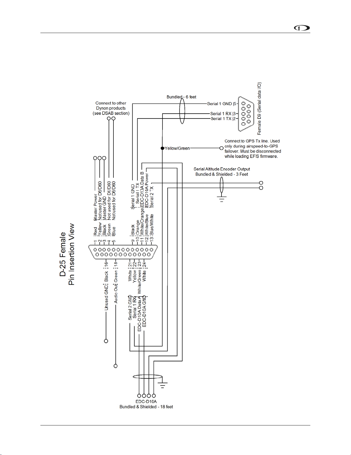
25-Pin Female EFIS Harness
Below is the wiring diagram of the EFIS 25-pin female harness. If you purchased your harness
from Dynon Avionics, it is color coded according to the chart on the following page. Unless
noted otherwise, all wires are 3 feet long on the Dynon-provided harness.
2-2 EFIS-D6 Installation Guide

Wiring Overview
The pin assignments for the female 25-pin harness are repeated below. Note that the pin numbers
are labeled on the face of both the female and male connector. Each connection on the harness
supplied by Dynon is color-coded. These colors are listed in the following chart.
For wires that are marked “(Unused in EFIS-D6)”, terminate these wires in an appropriate
manner (insure that they do not short). Dynon recommends not cutting or removing these wires
to preserve the option of upgrading the EFIS-D6 to an EFIS-D10A
Female
DB25
Dynon Harness Wire
Color
Function Details
Pin #
1 Red
Master Switch Power
(10-30 volts)
Page 3-3
2 Yellow (Unused in EFIS-D6)
3 Black Primary Ground Page 3-3
4 Green (Unused in EFIS-D6)
5 Blue (Unused in EFIS-D6)
6 N/A No Connect
7 N/A No Connect
8 N/A No Connect
9 Black (bundled) PC Serial Ground Page 3-4
10 Orange (bundled)
11
12
13
(Black on some harnesses)
(Black on some harnesses)
White/Orange
(Red on some harnesses)
White/Blue
Blue/White
EFIS-D6 Transmit / PC Serial
Serial Encoder Transmit (RS-232)
Receive (RS-232)
EDC-D10A Data B
EDC-D10A Power (12V)
Page 3-4
Page 3-2
Page 3-2
Page 5-15
14 N/A No Connect
15 N/A Emergency Backup Power Page 3-3
16 Black Ground
17 N/A No Connect
18 Green Audio out Page 3-7
19 N/A No Connect
20 N/A No Connect
21
White (Bundled in Encoder
cable)
22 Yellow (Bundled)
23
(Green on some harnesses)
White/Green
Serial Encoder Ground
EFIS-D6 Receive / PC Serial
Transmit (RS-232)
EDC-D10A Data A
Page 5-15
Page 3-4
Page 3-2
24 White EDC-D10A GND Page 3-2
25 N/A No Connect
EFIS-D6 Installation Guide 2-3
Wiring Overview
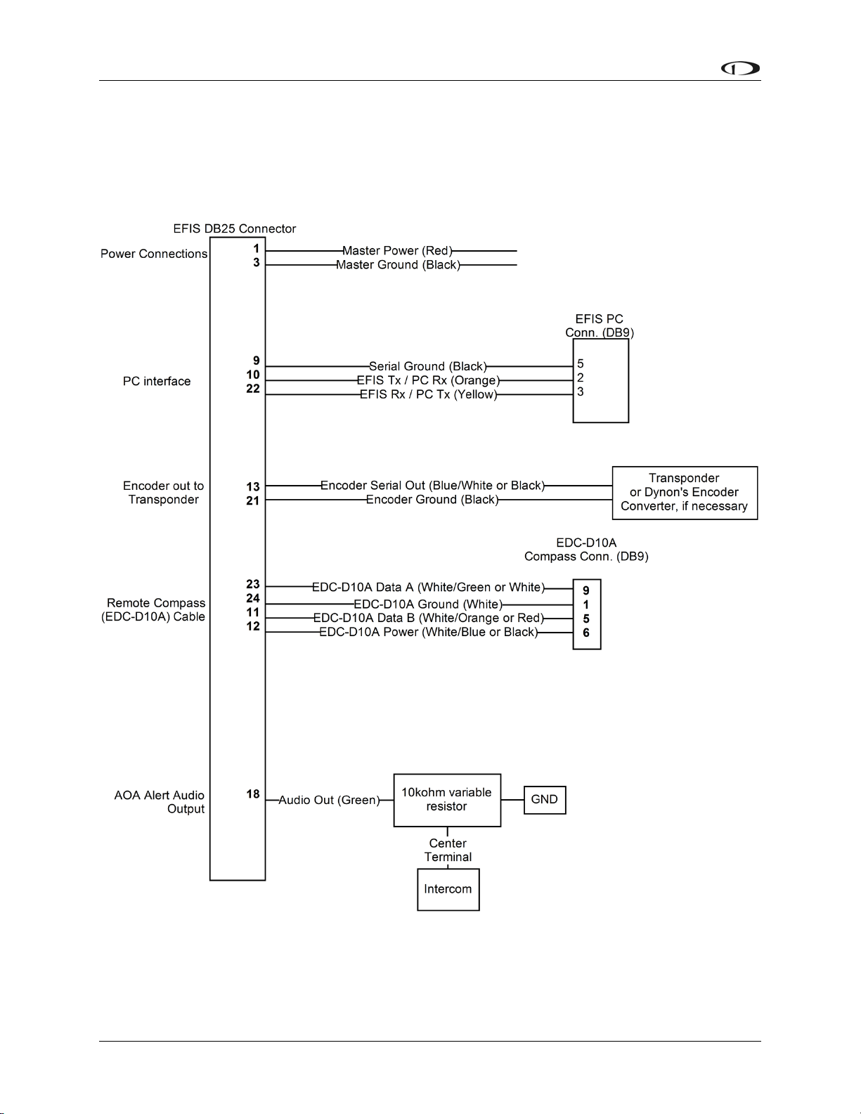
WIRING SYSTEM OVERVIEW
The following block diagram depicts the basic layout of the EFIS DB25 electrical connections
and is for reference only. Read the specific instructions for each connection prior to installation.
The colors shown refer to the Dynon-supplied EFIS harness.
2-4 EFIS-D6 Installation Guide
3. INSTRUMENT INSTALLATION
This section provides you with the information needed to physically and electrically install the
EFIS-D6. While the EFIS-D6 includes a built-in electronic compass, it is recommended to install
and calibrate the included EDC-D10A Remote Compass Module.
Selecting a Remote Compass Module Location
Finding a good location for the EDC-D10A
remote compass module is critical to an
accurate EFIS-D6 heading display. Keep in
mind that calibration can compensate for
small static magnetic fields superimposed
upon the earth’s field; it cannot take
into account dynamic effects like
AC currents, non-constant DC
currents and non-stationary ferrous
material (e.g., an electric turn
coordinator). Use the following
suggestions to help you find a good
location for your EDC-D10A.
• Keep the EDC-D10A away from
any source of magnetic fields
(such as electrical equipment and currentcarrying wires) and ferrous material.
• Move a handheld compass throughout the
space surrounding your location to get a ro
idea of the suitability of your chosen location
If the needle deviates significantly from
magnetic north in any given area, that locatio
would not be ideal for the EDC-D10A.
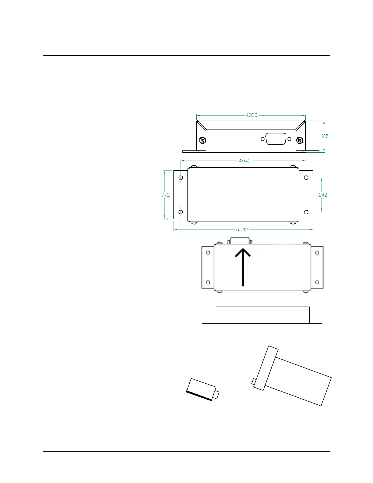
• The EDC-D10A can be mounted anywhe
the aircraft (away from magnetic interference)
such that its pitch is as close to that of the
EFIS-D6 as possible. It does not need to be
directly along any axis of the EFIS-D6. It
should be mounted with the long axis
parallel to the wings, the electrical
connector facing toward the front of th
plane, and the mounting tabs on the
bottom. The bracket used to hold the
EDC-D10A must hold the EDC-D10A
the same pitch, roll, and yaw as the EFISD6 with respect to the airframe. We
recommend that you use an electronic
level, if available, to make sure the EDC-
e
at
Connector toward
direction of flight
ugh
.
n
re in
Connector forward and
tabs mounted down
Side view of EDC-D10A, tabs mounted
down and aligned within 1 degree of pitch
with EFIS-D6
EFIS-D6 Installation Guide 3-1
Instrument Installation
D10A is aligned with the EFIS-D6 to better than 1 degree.
• All mounting hardware needs to be made from non-ferrous material such as aluminum,
plastic, or brass. Many stainless steel screws are magnetic. If the item is attracted to a
magnet, it should not be used in the installation. The EDC-D10A needs to be mounted
location as free from magnetic interference as possible. This means keeping the EDC-D10A
away from any ferrous nuts, bolts, and screws, aircraft tubing, as well as from wires or
devices carrying any appreciable current such as strobe light wiring, autopilot servos, or
other electronics.
in a
EDC-D10A Communication Cable
DO NOT ATTEMPT TO POWER UP THE EFIS-D6 WITH THE EDC CABLE LEADS
EXPOSED (UNSHEATHED) AND NOT INSTALLED IN THE DB9 CONNECTOR.
SHORTING THESE CONNECTIONS WILL CAUSE DAMAGE TO THE UNIT.
Like the RS-232 PC Communication cable, the EDC-D10A communications cable terminat
a standard female DB9 connector. While they look similar, do not plug the EDC cable into a PC
or vice versa. The following table outlines the four connections that must be made to ensure
proper communication between the EFIS-D6 and the EDC-D10A remote compass module. T
Dynon-supplied harness colors are listed, as well.
EFIS
DB25 pin#
11 5 EDC Data B White/Orange (or Red)
12 6 EDC Power White/Blue (or Black)
23 9 EDC Data A White/Green (or Green)
24 1 EDC Ground White
The EDC cable i e harness s lied b ts of 4 condu urrounded by a
metal shield and white insulation. These 4 wires are terminated with crimped female D-sub p
wrapped in plastic tubing. If you are building your own cable, we recommend that you use
shielded cable as well.
• With the 25-pin EFI
tubing off the 4 D-sub pins.
• Route the cable to the EDC-D
above.
• Install t
chart above.
• Install the bac
n th upp y Dynon consis ctors, s
he female pins in the correct holes on the included DB9 connector, according to the
k shell around the DB9 connector.
EDC
DB9 pin# Function Wire color
S harness disconnected from the EFIS-D6, carefully cut or pull the
10A mounting location chosen according to the instructions
es in
he
ins
Correct wiring installation can be easily verified once
the EDC-D10A connected to it. If you have correctly wired your EDC-D10A wiring harness yo
will see the heading properly displayed at the top of the screen (provided you have turned on the
heading display in the CLUTTR menu). If wiring is not correct, or the EDC-D10A is not
communicating properly with the EFIS-D6, you will see the message REMOTE COMPAS
NOT DETECTED in place of the heading onscreen.
3-2 EFIS-D6 Installation Guide
completed. Power on the EFIS-D6 with
u
S

Instrument Installation
The metal shield around the EDC communication cable is connected to the short black/white
wire from the DB25. Connect this wire to ground.
Power Inputs
The EFIS-D6 has two separate power inputs, located on the DB25 EFIS connector. Only Master
Switch Power is required to operate the instrument. The other input provides redundancy. Below
is a table that explains both power inputs and their purposes. Both inputs share a common ground
signal, wired to pin 3 on the EFIS connector.
EFIS
DB25
pin#
1 Master
3 Primary
15 Emergency
Function EFIS DB25
wire color
Red Provides primary power to the instrument. The
Switch
Power
Black Connect to ground. Must carry as much as 2
Ground
(Not wired in
Backup
Power
Dynon
harness)
Description
EFIS-D6 will switch on upon application of
power. Connect to a switched power source. Will
not be adversely affected by engine cranking.
amps.
Will operate the EFIS-D6 only if Master Switch
Power is not present. The transition from Master
Switch Power to External Backup Power will
bring up a warning, requiring you to press ACK
within 30 seconds to keep the unit operating. This
warning will also display when transitioning from
either Master or External Backup to Internal
Battery power.
EFIS Serial Harness
The EFIS-D6 has one RS-232 serial port that can be used for two purposes. The EFIS Serial port
(DB9) is used for:
• Connecting to a PC to use the Dynon Support Program to perform firmware upgrades,
configure checklists, and download internal logs. The Help Files of the Support Program
provide detailed instructions on these functions. The latest version of the Dynon Support
Program can be downloaded at downloads.dynonavionics.com
• Connecting a compatible GPS receiver to serve as a backup to airspeed in the event of a
blocked pitot.
EFIS-D6 Installation Guide 3-3
.
Loading...