


 Loading...
EMS-D120
Engine Monitoring System
Pilot’s User Guide
P/N 100592-000, Revision H For use with firmware version 5.4
August, 2010
Dynon Avionics
This product is not approved for installation in type certificated aircraft

Contact Information
Dynon Avionics, Inc.
19825 141st Place NE Woodinville, WA 98072
Phone: (425) 402-0433 - 7:00 AM – 5:00 PM (Pacific Time) Monday - Friday Fax: (425) 984-1751
Dynon Avionics offers online sales, extensive support, and continually-updated information on its products via its Internet sites:
www.dynonavionics.com –Dynon Avionics primary web site; including:
docs.dynonavionics.com – Current and archival documentation.
downloads.dynonavionics.com – Software downloads.
support.dynonavionics.com – Support resources.
store.dynonavionics.com – Dynon’s secure online store for purchasing all Dynon products 24 hours a day.
wiki.dynonavionics.com – Dynon Avionics’ Documentation Wiki provides enhanced, extended, continuously-updated online documentation contributed by Dynon employees and customers.
forum.dynonavionics.com – Dynon Avionics’ Internet forum where Dynon customers can interact and receive Dynon technical support outside of telephone support hours. A key feature of the forum is that it allows the exchange of diagrams, photos, and other types of files.
newsletter.dynonavionics.com – Dynon’s email newsletter.
blog.dynonavionics.com – Dynon’s blog where you can find new and interesting Dynon-related content.
Copyright
2003-2009 Dynon Avionics, Inc. All rights reserved. No part of this manual may be reproduced, copied, transmitted, disseminated or stored in any storage medium, for any purpose without the express written permission of Dynon Avionics. Dynon Avionics hereby grants permission to download a single copy of this manual and of any revision to this manual onto a hard drive or other electronic storage medium to be viewed for personal use, provided that such electronic or printed copy of this manual or revision must contain the complete text of this copyright notice and provided further that any unauthorized commercial distribution of this manual or any revision hereto is strictly prohibited.

Information in this document is subject to change without notice. Dynon Avionics reserves the right to change or improve its products and to make changes in the content without obligation to notify any person or organization of such changes. Visit the Dynon Avionics website (www.dynonavionics.com) for updates and supplemental information concerning the use and operation of this and other Dynon Avionics products.
Limited Warranty
Dynon Avionics warrants this product to be free from defects in materials and workmanship for three years from date of shipment. Dynon Avionics will, at its sole option, repair or replace any components that fail in normal use. Such repairs or replacement will be made at no charge to the customer for parts or labor. The customer is, however, responsible for any transportation cost. This warranty does not cover failures due to abuse, misuse, accident, improper installation or unauthorized alteration or repairs.
THE WARRANTIES AND REMEDIES CONTAINED HEREIN ARE EXCLUSIVE, AND IN LIEU OF ALL OTHER WARRANTIES EXPRESSED OR IMPLIED, INCLUDING ANY LIABILITY ARISING UNDER WARRANTY OF MERCHANTABILITY OR FITNESS FOR A PARTICULAR PURPOSE, STATUTORY OR OTHERWISE. THIS WARRANTY GIVES YOU SPECIFIC LEGAL RIGHTS, WHICH MAY VARY FROM STATE TO STATE.
IN NO EVENT SHALL DYNON AVIONICS BE LIABLE FOR ANY INCIDENTAL, SPECIAL, INDIRECT OR CONSEQUENTIAL DAMAGES, WHETHER RESULTING FROM THE USE, MISUSE OR INABILITY TO USE THIS PRODUCT OR FROM DEFECTS IN THE PRODUCT. SOME STATES DO NOT ALLOW THE EXCLUSION OF INCIDENTAL OR CONSEQUENTIAL DAMAGES, SO THE ABOVE LIMITATIONS MAY NOT APPLY TO YOU.
Dynon Avionics retains the exclusive right to repair or replace the instrument or firmware or offer a full refund of the purchase price at its sole discretion. SUCH REMEDY SHALL BE YOUR SOLE AND EXCLUSIVE REMEDY FOR ANY BREACH OF WARRANTY.
These instruments are not intended for use in type certificated aircraft at this time. Dynon Avionics makes no claim as to the suitability of its products in connection with FAR 91.205.
Dynon Avionics’ products incorporate a variety of precise, calibrated electronics. Except for replacing the optional internal backup battery in EFISbased products per the installation guide, our products do not contain any field/user-serviceable parts. Units that have been found to have been taken apart may not be eligible for repair under warranty. Additionally, once a Dynon Avionics unit is opened up, it will require calibration and verification at our Woodinville, WA offices before it can be considered airworthy.
EMS-D120 Pilot’s User Guide |
iii |

Table of Contents
Contact Information |
..............................................................................................................................................................ii |
Copyright.............................................................................................................................................................................. |
ii |
Limited Warranty ................................................................................................................................................................ |
iii |
1. Introduction |
1-1 |
Before You Fly .................................................................................................................................................................. |
1-1 |
OEM Installations.............................................................................................................................................................. |
1-1 |
Warning ............................................................................................................................................................................. |
1-2 |
About this Guide................................................................................................................................................................ |
1-2 |
2. |
Product Overview |
2-1 |
EMS-D120 Hardware........................................................................................................................................................ |
2-1 |
|
3. |
Product Operation |
3-1 |
Front Panel Layout ............................................................................................................................................................ |
3-1 |
|
Display............................................................................................................................................................................... |
3-2 |
|
Menus ................................................................................................................................................................................ |
3-6 |
|
4. |
Available Pages |
4-1 |
EMS Main Pages ............................................................................................................................................................... |
4-2 |
|
EMS Auxiliary Page.......................................................................................................................................................... |
4-3 |
|
EMS Times Page ............................................................................................................................................................... |
4-3 |
|
EMS Fuel Computer Page ................................................................................................................................................. |
4-4 |
|
Lists Pages......................................................................................................................................................................... |
4-5 |
|
|
|
|
EMS-D120 Pilot’s User Guide |
v |
|

Table of Contents
Menu Pages....................................................................................................................................................................... |
4-5 |
5. Alerts |
5-1 |
Alarm Indicators ............................................................................................................................................................... |
5-1 |
Multiple Alarms................................................................................................................................................................ |
5-3 |
Latching and Self-clearing Alarms ................................................................................................................................... |
5-4 |
DSAB Alerts..................................................................................................................................................................... |
5-4 |
6. |
EMS Monitoring Functions |
6-1 |
Engine Leaning and Power ............................................................................................................................................... |
6-1 |
|
Data Logging .................................................................................................................................................................... |
6-2 |
|
7. |
EMS Operation |
7-1 |
ON/OFF............................................................................................................................................................................ |
7-1 |
|
Display Brightness (DIM) ................................................................................................................................................ |
7-1 |
|
Fuel Computer .................................................................................................................................................................. |
7-2 |
|
Engine Leaning................................................................................................................................................................. |
7-3 |
|
Clock Setup....................................................................................................................................................................... |
7-3 |
|
Timers............................................................................................................................................................................... |
7-4 |
|
Global Configuration Settings .......................................................................................................................................... |
7-5 |
|
8. |
Appendix |
8-1 |
Appendix A: Serial Data Output....................................................................................................................................... |
8-1 |
|
Appendix B: PC Support Program.................................................................................................................................... |
8-5 |
|
Appendix C: Troubleshooting .......................................................................................................................................... |
8-5 |
|
Appendix D: EMS-D120 Specifications........................................................................................................................... |
8-6 |
|
vi |
EMS-D120 Pilot’s User Guide |

1. INTRODUCTION
Thank you for purchasing the Dynon Avionics EMS-D120. This section provides some important cautionary information and general usage instructions for this manual.
Before You Fly
We strongly recommended that you read this entire guide before attempting to use the EMS-D120 in an actual flying situation. Additionally, we encourage you to spend time on the ground familiarizing yourself with the operation of the product. While first learning to use the instrument in the air, we recommend you have a backup pilot with you in the aircraft. Finally, we encourage you to keep this manual in the aircraft with you at all times. This document is designed to give you quick access to information that might be needed in flight. CAUTION: in a flying situation, it is the pilot’s responsibility to use the product and the guide prudently.
OEM Installations
If your EMS-D120 is installed by an OEM distributor, you may find that you are unable to access some menus and settings. Some Dynon distributors customize various areas of the EMS-D120 firmware to maintain a consistent pilot experience and minimize integration issues across a large number of installations. Currently, OEMs can customize access levels to the following settings on Dynon systems: EMS GLOBAL setup menu, EMS SENSOR setup menu, fuel calibration, trim calibration, flaps calibration, GPS/NAV setup menu, screen configurations, data logging, and checklists/data panels. OEM distributors have the option of customizing some or all of these areas. Please contact your aircraft’s manufacturer if you have any questions about how your unit has been customized.
EMS-D120 Pilot’s User Guide |
1-1 |

Introduction
Warning
Dynon Avionics’ products incorporate a variety of precise, calibrated electronics. Except for replacing the optional internal backup battery in EFIS-based products per the installation guide, our products do not contain any field/userserviceable parts. Units that have been found to have been taken apart may not be eligible for repair under warranty. Additionally, once a Dynon Avionics unit is opened up, it will require calibration and verification at our Woodinville, WA offices before it can be considered airworthy.
About this Guide
This guide serves two purposes. The first is to help you configure and get acquainted with the EMS-D120‘s many functions. The second is to give you quick access to vital information. For detailed technical and installation information, please refer to the EMS-D120 Installation Guide.
In the electronic (.PDF) version of this manual, page and section references in the Table of Contents and elsewhere act as hyperlinks taking you to the relevant location in the manual. The latest version of this manual may be downloaded from our website at docs.dynonavionics.com.
This guide discusses the most common operation scenarios. If you have an operational issue that is not discussed in this guide, you can find additional operational information on Dynon’s Internet sites:
wiki.dynonavionics.com – Dynon’s Documentation Wiki provides enhanced, extended, frequently updated online documentation contributed by Dynon employees and customers.
forum.dynonavionics.com – Dynon’s Online Customer Forum is a resource for Dynon Avionics customers to discuss installation and operational issues relating to Dynon Avionics products. The Forum is especially useful for pilots with uncommon aircraft or unusual installation issues. For customers that cannot call Dynon Technical Support during our normal business hours, the Forum is a convenient way to interact with Dynon Avionics Technical Support. The Forum allows online sharing of wiring diagrams, photos, and other types of electronic files.
1-2 |
EMS-D120 Pilot’s User Guide |

Introduction
The following icons are used in this guide:
Any text following this icon describes functionality available only with the HS34 HSI Expansion Module connected to your system.
Any text following this icon describes functionality available only with the AP74 Autopilot Interface Module connected to your system.
Any text following this icon describes functionality that is possible when multiple Dynon Avionics products are networked together via the Dynon Smart Avionics Bus (DSAB).
Any text following this icon refers to a setting or situation which merits particularly close attention.
EMS-D120 Pilot’s User Guide |
1-3 |

2. PRODUCT OVERVIEW
This EMS-D120 monitors your engine and other vital aircraft systems and displays information in an easy-to-read format. This section provides a general overview of the various parts of the EMS-D120 as well as a theory of operation. The information in this section serves as a reference only and helps familiarize you with the inner workings of the unit. It should not be used for diagnostic or reparative work.
EMS-D120 Hardware
The EMS-D120’s versatile design accommodates a wide range of engines and sensors. You may configure the system to meet your monitoring requirements covering both airand water-cooled engines with up to six cylinders. Its warning capabilities provide early notification of problems that might otherwise go unnoticed.
POWER
The EMS-D120 requires between 10 and 30 volts DC for operation. It is acceptable to have the EMS-D120 turned on during engine start.
SENSORS AND INPUTS
When connected to the appropriate sensors, the EMS-D120 displays RPM, manifold pressure, oil temperature and pressure, exhaust gas temperature (EGT), cylinder head temperature (CHT), fuel levels for up to 4 tanks, voltage, current, fuel pressure, fuel flow, carburetor air temperature, coolant pressure and temperature, outside air temperature, flaps, trim, and the status of up to two external contacts. Fuel endurance and economy information can be obtained when a compatible GPS unit is connected to your system.
EMS-D120 Pilot’s User Guide |
2-1 |

Product Overview
DYNON SMART AVIONICS BUS
If you have multiple Dynon Avionics products in your aircraft, they may be networked together via the Dynon Smart Avionics Bus (DSAB). Units networked via DSAB have the ability to transmit information to each other. Any product's data can then be viewed on any other screen in the DSAB network. For example, an EFIS has the ability to display engine monitor information if it is connected to an EMS or FlightDEK-D180.
Note that the failure of a unit in a DSAB network may cause the loss of some or all data shared between units. In the above example, if the connected EMS/FlightDEK-D180 were to fail, the EFIS would no longer be able to behave as an engine monitor. For more information on DSAB-specific alerts, refer to the DSAB Alerts section on page 5-4.
OUTPUTS
The EMS-D120 has outputs to drive external customer-supplied audible and visual devices for engine, AOA (if installed) and altitude alerts.
A connected HS34 or AP74 can output voice annunciations for many of the alerts generated by the EMS-D120.
DISPLAY
The display is a 7-inch, 854 by 480 pixel, 400 nit or 800 nit LCD screen, depending on the model.
BUTTONS
User interaction takes place via the six buttons along the bottom of the front panel of the unit.
2-2 |
EMS-D120 Pilot’s User Guide |
3. PRODUCT OPERATION
After reading this section, you will be familiar with the basics of how to use your EMS-D120. For details regarding specific procedures (e.g., adjusting display brightness, using the fuel computer, setting the clock, etc.) please refer to the EMS Operation section.
Front Panel Layout
All normal operation of the EMS-D120 happens via the front panel. The front panel contains buttons and a display.
Buttons – There are six buttons on the front panel of the EMS-D120. Throughout this guide, these buttons are referred to as one through six, with button one being the leftmost and button six being the rightmost. EMS-D120 buttons are used to turn the instrument on and off, cycle between screens, scroll through menus, and adjust instrument parameters.
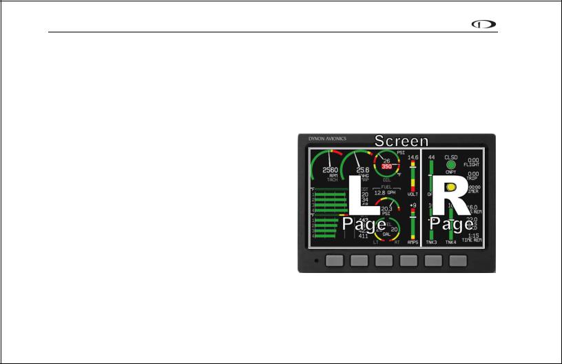
Display – The display shows engine parameters, menus, and data obtained from other connected products.
1 |
2 |
3 |
4 |
5 |
6 |
User interaction takes place via the EMS-D120 main display and the six buttons beneath. Note: buttons are not labeled on actual product
EMS-D120 Pilot’s User Guide |
3-1 |
Product Operation
Display
The EMS-D120 display is the most obvious and commonly used output of the device. It is capable of displaying EFIS, HSI, and/or engine data simultaneously.
SCREENS AND PAGES
The terms in the following bulleted list are used in this section and are defined as follows:
Screen/Screen Configuration – Screens consist of one or two pages from the EMS-D120 or from another DSABconnected Dynon Avionics product.
Page – A page is a section of the screen that contains a collection of related data. Pages may occupy the total area of the screen (i.e., 100%) or share the screen with other pages (e.g., 2/3, 1/3 split). Pages that occupy 1/3 of the screen area are sometimes abbreviated versions of their full size (100% or 2/3) counterparts.
Screen Rotation – The rotation is the list of screen configurations which can be cycled to via the hotkeys. Your rotation is usually smaller than the total list of available screen configurations.
Screens contain one or two pages and pages contain groups of similar information.
3-2 |
EMS-D120 Pilot’s User Guide |

Product Operation
The EMS-D120 has several pre-defined screen configurations. The basic layout of a screen configuration is represented by one of three icons on D100-series product. The table at right shows the three icons and their meaning.
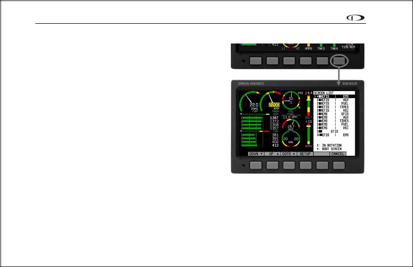
The predefined screen configurations with their respective icons are as follows:
Icon |
Left Page Area |
|
Right Page Area |
|
2/3 |
|
1/3 |
|
1/3 |
|
2/3 |
|
|
|
|
|
One page that occupies all of the screen |
||
|
|
area |
|
The SCREEN LIST Menu uses icons to illustrate the layout for each screen configuration.
 EFIS/EMS
 EFIS/AUX
 EFIS/FUEL
 EFIS/TIMES
 EFIS/HSI
 EMS/EFIS
 EMS/AUX (default EMS-D120 boot-up screen; in default rotation)
 EMS/TIMES (in default screen rotation)
 EMS/FUEL
 EMS/HSI
 EFIS
EFIS
 EFIS/EMS
 EMS/EFIS
 HSI/EMS
EMS-D120 Pilot’s User Guide |
3-3 |
Product Operation
CYCLING BETWEEN SCREENS
There are two methods for cycling between pre-defined screens: via the menu and via hotkeys.
Screen Cycling Using the SCREEN LIST
Navigate to the SCREEN LIST menu by holding button six for at least two seconds when no menu is present (see the figure to the right). Note that if you only press button six momentarily, the display cycles to the next screen in your screen rotation. Use the DOWN▼/UP▲ buttons to move the caret (>). The caret denotes the selected screen. Press GOTO► to remove the SCREEN LIST and display the selected screen. If you wish to stay on the same screen, you may either select your currently displayed screen with the caret and press GOTO►, or press CANCEL.
Screen Cycling Using Hotkeys
With no menu displayed, press button one to cycle to the previous screen in your rotation. Likewise, press button six to cycle to the next screen in your rotation (see the figure on the next page). Cycling via hotkeys only allows you to display screens that are in your screen rotation. They are meant to give you quick access to the screen configurations that are most important to you. If you wish to access
screens that are not in your rotation, use the SCREEN LIST as described above.
3-4 |
EMS-D120 Pilot’s User Guide |
Loading...