


 Loading...
L Series and C Series FIR-Drive Power
Amplifiers
en | Installation manual

L Series and C Series FIR-Drive Power |
Table of Contents | en |
3 |
|
Amplifiers |
|||
|
|
||
|
|
|
Table of contents
1 |
Safety |
5 |
1.1 |
Safety messages explained |
5 |
1.2 |
Important safety instructions |
5 |
1.3 |
Safety precautions |
7 |
1.4 |
FCC |
8 |
1.5 |
Notices |
8 |
2 |
About this manual |
9 |
2.1 |
Manual purpose |
9 |
2.2 |
Digital document |
9 |
2.3 |
Intended audience |
9 |
2.4 |
Short Information |
9 |
3 |
System overview |
11 |
3.1 |
Application area |
11 |
3.2 |
Features |
11 |
3.3 |
Unpacking and inspection |
11 |
3.4 |
Scope of delivery |
11 |
4 |
|
|
Planning information |
13 |
|
5 |
|
|
Installation |
14 |
|
5.1 |
Operating voltage |
14 |
5.2 |
Power |
14 |
5.2.1 |
L Series |
14 |
5.2.2 |
C Series |
14 |
5.3 |
Mounting |
15 |
5.4 |
Ventilation |
15 |
6 |
|
|
Controls, indicators and connections |
17 |
|
6.1 |
L Series amplifier |
17 |
6.2 |
C Series amplifier |
18 |
6.3 |
Fan cooling |
18 |
6.4 |
Groundlift |
19 |
6.5 |
USB B connector |
19 |
6.6 |
Power remote |
19 |
6.7 |
Power on delay |
19 |
6.8 |
GPI/GPO |
19 |
6.9 |
Power outputs |
20 |
6.9.1 |
L Series amplifier |
20 |
6.9.2 |
C Series amplifier |
21 |
6.10 |
Audio input cabling |
22 |
6.10.1 |
Audio input cabling for XLR-type connectors |
22 |
6.10.2 |
Audio input cabling for Euroblock-type connectors |
23 |
7 |
|
|
Power amplifier menu navigation |
24 |
|
7.1 |
Amplifier and DSP control |
24 |
7.2 |
DSP control menu |
24 |
7.3 |
Factory presets |
26 |
8 |
|
|
Technical data |
29 |
|
8.1 |
C Series direct drive load capability |
34 |
8.2 |
Mains operation & resulting temperature |
35 |
Bosch Sicherheitssysteme GmbH |
Installation manual |
2017.10 | 02 | F.01U.327.801 |

4 |
en | Table of Contents |
L Series and C Series FIR-Drive Power |
|
Amplifiers |
|||
|
|
||
|
|
|
|
8.3 |
Block diagrams |
38 |
|
8.4 |
Dimensions |
40 |
2017.10 | 02 | F.01U.327.801 |
Installation manual |
Bosch Sicherheitssysteme GmbH |
L Series and C Series FIR-Drive Power |
Safety | en |
5 |
|
Amplifiers |
|||
|
|
||
|
|
|
1 |
Safety |
1.1 |
Safety messages explained |
|
Four types of signs can be used in this manual. The type is closely related to the effect that |
|
may be caused if it is not observed. These signs - from least severe effect to most severe |
|
effect - are: |
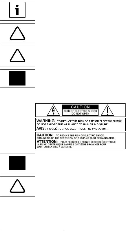
Notice!
Containing additional information. Usually, not observing a ‘notice’ does not result in damage to the equipment or personal injuries.
Caution!
!The equipment or the property can be damaged, or persons can be lightly injured if the alert is not observed.
Warning!
!The equipment or the property can be seriously damaged, or persons can be severely injured if the alert is not observed.
Danger!
Not observing the alert can lead to severe injuries or death.
1.2 |
Important safety instructions |
Danger!
The lightning symbol inside a triangle notifies the user of high-voltage, uninsulated lines and contacts inside the devices that could result in fatal electrocution if touched.
Warning!
!An exclamation mark inside a triangle refers the user to important operating and service instructions in the documentation for the equipment.
1.Read these safety notes.
2.Keep these safety notes in a safe place.
3.Heed all warnings.
4.Observe all instructions.
Bosch Sicherheitssysteme GmbH |
Installation manual |
2017.10 | 02 | F.01U.327.801 |

6 |
en | Safety |
L Series and C Series FIR-Drive Power |
|
Amplifiers |
|||
|
|
||
|
|
|
5.Do not operate the device in close proximity to water.
6.Use only a dry cloth to clean the unit.
7.Do not cover any ventilation slots. Always refer to the manufacturer's instructions when installing the device.
8.Do not install the device close to heaters, ovens, or other heat sources.
9.Note: The device must only be operated via the mains power supply with a safety ground connector. Do not disable the safety ground connection function of the supplied power cable. If the plug of the supplied cable does not fit your mains socket, please contact your electrician.
10.Ensure that it is not possible to stand on the mains cable. Take precautions to ensure the mains cable cannot become crushed, particularly near the device connector and mains plug.
11.Only use accessories/extensions for the device that have been approved by the manufacturer.
12.Unplug the device if there is risk of lightning strike or in the event of long periods of inactivity. However, this does not apply if the device is to be used as part of an evacuation system!
13.Have all service work and repairs performed by a trained customer service technician only. Service work must be carried out immediately following any damage such as damage to the mains cable or plug, if fluid or any object enters the device, if the device has been used in rain or become wet, or if the device has been dropped or no longer works correctly.
14.Please ensure that no dripping water or spray can penetrate the inside of the device. Do not place any objects filled with fluids, such as vases or drinking vessels, on top of the device.
15.To ensure the device is completely free of voltage, unplug the device from the power supply.
16.When installing the device, ensure that the plug is freely accessible.
17.Do not place any sources of open flame, such as lit candles, on top of the device.
18.This PROTECTION CLASS I device must be connected to a MAINS socket with a safety ground connection.
Caution!
Use only manufacturer-approved carts, stands, brackets, or tables that you acquired together with the device. When using carts to move the device, make sure the transported equipment and the cart itself cannot tip over or cause injury or material damage.
IMPORTANT SERVICE INFORMATION
Caution!
This service information is for use by qualified service personnel only. To avoid the risk of
!electric shock, do not perform any maintenance work that is not described in the operating instructions unless you are qualified to do so. Have all service work and repairs performed by a trained customer service technician.
1.Repair work on the device must comply with the safety standards specified in EN 60065 (VDE 0860).
2.A mains isolating transformer must be used during any work for which the opened device is connected to and operated with mains voltage.
2017.10 | 02 | F.01U.327.801 |
Installation manual |
Bosch Sicherheitssysteme GmbH |

L Series and C Series FIR-Drive Power |
Safety | en |
7 |
|
Amplifiers |
|||
|
|
||
|
|
|
3. The device must be free of any voltage before performing any alterations with upgrade sets, switching the mains voltage, or performing any other modifications.
4. The minimum distance between voltage-carrying parts and metal parts that can be touched (such as the metal housing) or between mains poles is 3 mm, and must be observed at all times.
5. The minimum distance between voltage-carrying parts and circuit parts that are not connected to the mains (secondary) is 6 mm, and must be observed at all times.
6. Special components that are marked with the safety symbol in the circuit diagram (note) must only be replaced with original parts.
7. Unauthorized changes to the circuitry are prohibited.
8. The protective measures issued by the relevant trade organizations and applicable at the place of repair must be observed. This includes the properties and configuration of the workplace.
9. Observe the guidelines with respect to handling MOS components.
Danger!
SAFETY COMPONENT (MUST BE REPLACED BY ORIGINAL PART)
1.3 Safety precautions
Speaker system damage and protection of human beings
Power amps provide extremely high power output that might be dangerous for human beings as well as for the connected speaker systems. High output voltages can damage or even destroy the connected speaker systems, especially, when the amplifier is operated in bridged mode. Prior to connecting any loudspeakers, make sure to check the speaker system’s specifications for continuous and peak power handling capacities. Even if amplification has been reduced through lowering the input level controls on the amplifier’s front panel, it is still possible to achieve full power output with a sufficiently high input signal.
Danger!
Danger at the loudspeaker/power outputs
Power amplifiers are capable of producing dangerously high voltage output that is present at the output connectors.
To protect yourself from electric shock, do not touch any blank speaker cables during operation of the power amp.
Danger!
The terminals marked with a lightning bolt are hazardous live and the external wiring connected to these terminals requires installation by an instructed person or the use of readymade leads of cords.
Danger!
In case of using the amplifier with speakers including a primary tapped transformer, it is possible that during operation shock hazard voltages may be present at the taps of the transformer.
Therefore, the taps have to be insulated sufficiently in accordance with applicable safety regulations.
Bosch Sicherheitssysteme GmbH |
Installation manual |
2017.10 | 02 | F.01U.327.801 |

8 |
en | Safety |
L Series and C Series FIR-Drive Power |
|
Amplifiers |
|||
|
|
||
|
|
|
1.4 FCC
IMPORTANT: Do not modify this unit! Changes or modifications not expressly approved by the manufacturer could void the user’s authority, granted by the FCC, to operate the equipment.
Notice!
This equipment has been tested and found to comply with the limits for a Class B digital device, pursuant to Part 15 of the FCC Rules. These limits are designed to provide reasonable protection against harmful interference in a residential installation. This equipment generates, uses and can radiate radio frequency energy and, if not installed and used in accordance with the instructions, may cause harmful interference to radio communications. However, there is no guarantee interference will not occur in a particular installation.
If this equipment does cause harmful interference to radio or television reception or receive audible interference from radio, television or communications equipment, which can be determined by turning the equipment off and on. The user is encouraged to try to correct the interference by one or more of the following measures:
•Reorient or relocate the receiving antenna.
•Increase the separation between the equipment and receiver.
•Connect the equipment into an outlet on a circuit different from that to which the receiver is connected.
•Consult the dealer or an experienced radio/TV/communications equipment technician.
1.5 Notices
Old electrical and electronic appliances
Electrical or electronic devices that are no longer serviceable must be collected separately and sent for environmentally compatible recycling (in accordance with the European Waste Electrical and Electronic Equipment Directive).
To dispose of old electrical or electronic devices, you should use the return and collection systems put in place in the country concerned.
Copyright and disclaimer
All rights reserved. No part of this document may be reproduced or transmitted in any form by any means, electronic, mechanical, photocopying, recording, or otherwise, without the prior written permission of the publisher. For information on getting permission for reprints and excerpts, contact Dynacord.
The content and illustrations are subject to change without prior notice.
2017.10 | 02 | F.01U.327.801 |
Installation manual |
Bosch Sicherheitssysteme GmbH |

L Series and C Series FIR-Drive Power |
About this manual | en |
9 |
|
Amplifiers |
|||
|
|
||
|
|
|
2 |
About this manual |
|
2.1 |
Manual purpose |
|
|
The purpose of this manual is to provide information required for installing, configuring, |
|
|
operating and maintaining the L Series FIR-Drive Power Amplifier and C Series FIR-Drive |
|
|
Power Amplifier hardware products. |
|
|
Read through this manual to familiarize yourself with the safety information, features, and |
|
|
applications before you use these products. |
|
2.2 |
Digital document |
|
|
This manual is available as a digital document in the Adobe Portable Document Format (PDF). |
|
|
You can find information about Dynacord products on the product related information at |
|
|
www.dynacord.com. |
|
2.3 |
Intended audience |
|
|
This manual is intended for installers, operators, and users of L/C series powered amplifier |
|
|
systems. |
|
2.4 |
Short Information |
|
|
The following table lists products in a family, with CTN (Commercial Type Number) and |
|
|
identifying product name DESCRIPTION. |
|
|
|
|
|
CTN |
Description |
|
|
|
|
L Series |
|
|
|
|
|
L1300FD-AU |
DSP power amplifier 2x650W AU |
|
|
|
|
L1300FD-CN |
DSP power amplifier 2x650W CN |
|
|
|
|
L1300FD-EU |
DSP power amplifier 2x650W EU |
|
|
|
|
L1300FD-JP |
DSP power amplifier 2x650W JP |
|
|
|
|
L1300FD-UK |
DSP power amplifier 2x650W UK |
|
|
|
|
L1300FD-US |
DSP power amplifier 2x650W US |
|
|
|
|
L1800FD-AU |
DSP power amplifier 2x950W AU |
|
|
|
|
L1800FD-CN |
DSP power amplifier 2x950W CN |
|
|
|
|
L1800FD-EU |
DSP power amplifier 2x950W EU |
|
|
|
|
L1800FD-JP |
DSP power amplifier 2x950W JP |
|
|
|
|
L1800FD-UK |
DSP power amplifier 2x950W UK |
|
|
|
|
L1800FD-US |
DSP power amplifier 2x950W US |
|
|
|
|
L2800FD-AU |
DSP power amplifier 2x1400W AU |
|
|
|
|
L2800FD-CN |
DSP power amplifier 2x1400W CN |
|
|
|
|
L2800FD-EU |
DSP power amplifier 2x1400W EU |
|
|
|
|
L2800FD-JP |
DSP power amplifier 2x1400W JP |
|
|
|
Bosch Sicherheitssysteme GmbH |
Installation manual |
2017.10 | 02 | F.01U.327.801 |

10 en | About this manual |
L Series and C Series FIR-Drive Power |
|
Amplifiers |
||
|
||
|
|
CTN |
Description |
|
|
L2800FD-UK |
DSP power amplifier 2x1400W UK |
|
|
L2800FD-US |
DSP power amplifier 2x1400W US |
|
|
L3600FD-AU |
DSP power amplifier 2x1800W AU |
|
|
L3600FD-CN |
DSP power amplifier 2x1800W CN |
|
|
L3600FD-EU |
DSP power amplifier 2x1800W EU |
|
|
L3600FD-JP |
DSP power amplifier 2x1800W JP |
|
|
L3600FD-UK |
DSP power amplifier 2x1800W UK |
|
|
L3600FD-US |
DSP power amplifier 2x1800W US |
|
|
C Series |
|
|
|
C1300FDi-AU |
DSP power amplifier 2x650W, install AU |
|
|
C1300FDi-CN |
DSP power amplifier 2x650W, install CN |
|
|
C1300FDi-EU |
DSP power amplifier 2x650W, install EU |
|
|
C1300FDi-JP |
DSP power amplifier 2x650W, install JP |
|
|
C1300FDi-UK |
DSP power amplifier 2x650W, install UK |
|
|
C1300FDi-US |
DSP power amplifier 2x650W, install US |
|
|
C1800FDi-AU |
DSP power amplifier 2x950W, install AU |
|
|
C1800FDi-CN |
DSP power amplifier 2x950W, install CN |
|
|
C1800FDi-EU |
DSP power amplifier 2x950W, install EU |
|
|
C1800FDi-JP |
DSP power amplifier 2x950W, install JP |
|
|
C1800FDi-UK |
DSP power amplifier 2x950W, install UK |
|
|
C1800FDi-US |
DSP power amplifier 2x950W, install US |
|
|
C2800FDi-AU |
DSP power amplifier 2x1400W, install AU |
|
|
C2800FDi-CN |
DSP power amplifier 2x1400W, install CN |
|
|
C2800FDi-EU |
DSP power amplifier 2x1400W, install EU |
|
|
C2800FDi-JP |
DSP power amplifier 2x1400W, install JP |
|
|
C2800FDi-UK |
DSP power amplifier 2x1400W, install UK |
|
|
C2800FDi-US |
DSP power amplifier 2x1400W, install US |
|
|
C3600FDi-AU |
DSP power amplifier 2x1800W, install AU |
|
|
C3600FDi-CN |
DSP power amplifier 2x1800W, install CN |
|
|
C3600FDi-EU |
DSP power amplifier 2x1800W, install EU |
|
|
C3600FDi-JP |
DSP power amplifier 2x1800W, install JP |
|
|
C3600FDi-UK |
DSP power amplifier 2x1800W, install UK |
|
|
C3600FDi-US |
DSP power amplifier 2x1800W, install US |
|
|
2017.10 | 02 | F.01U.327.801 |
Installation manual |
Bosch Sicherheitssysteme GmbH |
L Series and C Series FIR-Drive Power |
System overview | en 11 |
|
Amplifiers |
||
|
||
|
|
3 |
|
System overview |
|||
3.1 |
|
Application area |
|
||
|
|
The L Series and C Series power amplifier are designed to power professional loudspeaker |
|||
|
|
system in live and fix installed audio applications such as concerts, clubs, sports venues, |
|||
|
|
HOWs and many other applications. |
|||
3.2 |
|
Features |
|
||
|
|
L Series |
|
||
|
|
• |
Live performance DSP amplifier |
||
|
|
• |
Fully integrated professional speaker processing with FIR Drive technology |
||
|
|
• |
Market leading acoustic performance and rock solid reliability |
||
|
|
• |
True 2 ohm stability |
|
|
|
|
• |
Intuitive system control software, makes setup and control easy |
||
|
|
C Series |
|
||
|
|
• |
Installation DSP amplifier, Euroblock connectors |
||
|
|
• |
Fully integrated professional speaker processing with FIR Drive technology |
||
|
|
• |
Market leading acoustic performance and rock solid reliability |
||
|
|
• |
Low Z and 70/100V operation and power saving standby mode |
||
|
|
• |
Intuitive system control software, makes setup and control easy |
||
3.3 |
|
Unpacking and inspection |
|||
|
|
Carefully open the packaging and take out the power amplifier. Inspect the power amp’s |
|||
|
|
enclosure for damages that might have happened during transportation. Each amplifier is |
|||
|
|
examined and tested in detail before leaving the manufacturing site to ensure that it arrives in |
|||
|
|
perfect condition at your place. Please inform the transport company immediately, if the |
|||
|
|
power amplifier shows any damage. Being the addressee, you are the only person who can |
|||
|
|
claim damages in transit. Keep the cardboard box and all packaging materials for inspection |
|||
|
|
by the transport company. |
|||
|
|
Keeping the cardboard box including all packing materials is also recommended, if the power |
|||
|
|
amplifier shows no external damages. |
|||
|
|
|
|
|
|
|
|
Caution! |
|
||
|
! |
Do not ship the power amp in any other but its original packaging. |
|||
|
|
|
|
|
|
|
|
|
|
||
|
|
When shipping the power amp, make sure to always use its original box and packaging |
|||
|
|
materials. Packing the power amplifier like it was packed by the manufacturer guarantees |
|||
|
|
optimum protection from transport damage. |
|||
3.4 |
|
Scope of delivery |
|
||
|
|
|
|
|
|
|
|
Quantity |
|
Component |
|
|
|
|
|
|
|
|
|
1 |
|
|
DSP amplifier |
|
|
|
|
|
|
|
|
1 |
|
|
Mains cord |
|
|
|
|
|
|
|
|
1 |
|
|
USB cable |
|
|
|
|
|
|
Bosch Sicherheitssysteme GmbH |
Installation manual |
2017.10 | 02 | F.01U.327.801 |

12 en | System overview |
L Series and C Series FIR-Drive Power |
|
Amplifiers |
||
|
||
|
|
Quantity |
Component |
|
|
1 |
Installation manual |
|
|
1 |
Safety instruction card |
|
|
Table 3.1: L Series |
|
|
|
Quantity |
Component |
|
|
1 |
DSP amplifier |
|
|
1 |
Mains cord |
|
|
1 |
USB cable |
|
|
1 |
Euroblock GPIO connector 6 pole |
|
|
1 |
Euroblock output connector 4 pole |
|
|
2 |
Euroblock input connectors 3 pole |
|
|
1 |
Power remote connector 2 pole |
|
|
1 |
Installation manual |
|
|
1 |
Safety instruction card |
|
|
Table 3.2: C Series |
|
Keep the original invoice that states the purchase/delivery date in a safe place.
2017.10 | 02 | F.01U.327.801 |
Installation manual |
Bosch Sicherheitssysteme GmbH |

L Series and C Series FIR-Drive Power |
Planning information | en 13 |
|
Amplifiers |
||
|
||
|
|
4 Planning information
Ensure the following:
•You make use of manufacturer specified installation materials.
•No liquids can spill into or on the products.
•Installation is in a clean environment free of dust.
•The ventilation airflow of the 19" units is not obstructed.
•There is a mains power outlet of sufficient rating close to the intended location of the products.
•Sufficient free space and access at the rear of the 19" units for connectors and wiring.
To find current user documentation, firmware, or software visit our product related information at www.dynacord.com.
Bosch Sicherheitssysteme GmbH |
Installation manual |
2017.10 | 02 | F.01U.327.801 |

14 en | Installation |
L Series and C Series FIR-Drive Power |
|
Amplifiers |
||
|
||
|
|
5 |
Installation |
5.1 |
Operating voltage |
|
The power amplifier receives its power supply via the MAINS IN connector. Only the provided |
|
power cord may be used. During installation, always separate the power amplifier from the |
|
mains. Connect the power amplifier only to a mains network, which corresponds to the |
|
requirements indicated on the type plate. |
5.2 |
Power |
|
The L Series power button is located on the front of the amplifier panel. The C Series power |
|
switch is located on the rear of the amplifier panel. |
5.2.1 |
L Series |
|
The Power button on the front panel separates the power amp from the mains. Pressing the |
|
Power button turns on the power amp. A soft start circuit compensates mains inrush current |
|
peaks and thus prevents triggering AC mains fuse when switching on the amplifier. Speaker |
system switch-on is delayed by approximately two seconds via output relays, effectively suppressing any possible power-on noise, which otherwise might be heard through the loudspeakers.
|
Figure 5.1: Power button on the front panel (L Series) |
5.2.2 |
C Series |
|
The Power/Standby switch on the rear panel is used to turn on the power to the amplifier or |
|
put the amplifier into standby mode. To separate the amplifier from the mains it is required to |
disconnect the mains power connection. A soft start circuit compensates mains inrush current peaks and thus prevents the automatic cutout of the mains from reacting when switching on the power amplifier. Speaker system switch-on is delayed by approximately two seconds via output relays, effectively suppressing any possible power-on noise, which otherwise might be heard through the loudspeakers. PROTECT-LED lights up and fans are at high speed during this delay. This indicates all protections are working fine.
Figure 5.2: Mains switch on the rear panel (C Series)
2017.10 | 02 | F.01U.327.801 |
Installation manual |
Bosch Sicherheitssysteme GmbH |
Loading...