


INTRODUCTION
1. INTRODUCTION
Preamble
Thank you for choosing the DYNACORD PROANNOUNCE System. With the PROANNOUNCE System you purchased a high-quality product which is going to satisfy your highest demands. This extraordinarily flexible and versatile system allows the configuration of either small or complex installations as well. Most functions are realized through software modules, which - when compared to conventional PA-systems – not only reduces the amount of cabling but also the costs. Next to extensive audio signal generating and distribution functions, the PROANNOUNCE system provides ample control functions. On one hand, these functions offer the possibility to register and rate external events, as well as to control different external components, on the other hand. Boolean operations and relations to the internal state of the system can be programmed as well.
To be able to take advantage of all possibilities that are offered by the PROANNOUNCE system, we would like to ask you to read this handbook carefully. For getting a quick overview about the PROANNOUNCE system's components and functions, we recommend consulting the chapter System Description.
Owner’s Manual
This handbook provides all the information that is necessary for planning and installing a PROANNOUNCE system. The handbook is structured in different chapters, each explaining a specific component or function. Thus, you can skip a section, if it is of no relevance for your particular application. The following table lists all chapters included in the handbook. It is meant as a guide for finding relevant information as quickly as possible.
1. |
Introduction |
Notes on how to use the handbook |
2. |
Operation Instructions |
Precautions, operational conditions, environmental conditions, location, |
|
|
initial operation, maintenance and service |
3. |
System Description |
Overview of all components (appliances), audio and control functions of |
|
|
the PROANNOUNCE system |
4. |
Installation |
Notes on how to install the PROANNOUNCE DESIGNER |
|
|
configuration software |
5. |
Single Device Descriptions |
Detailed descriptions of all PROANNOUNCE components: central unit with |
|
|
modules, paging stations, power amplifiers, monitoring system |
6. |
Appendix |
Notes on how to configure the hardware, wiring, and initial operation |
PROANNOUNCE System User Handbook 1.1 |
1-1 |
OPERATION INSTRUCTIONS
2.Operation Instructions
2.1Safety Instructions
IMPORTANT SAFETY INSTRUCTIONS
CAUTION
RISK OF ELECTRIC SHOCK
DO NOT OPEN
WARNING:


DO NOT EXPOSE THIS APPLIANCE TO RAIN OR MOISTURE. AVIS: RISQUÉ DE CHOC ELECTRIQUE. NE PAS OUVRIR.
The symbol of a flash within an equilateral triangle is to alert the user to the presence of uninsulated dangerous voltage within the product's enclosure that may be of sufficient magnitude to constitute a risk of electric shock to persons.
The symbol of an exclamation mark within an equilateral triangle is to alert the user's attention to the presence of important operating and maintenance (servicing) instructions in the literature accompanying the appliance
1.Please carefully read all instructions.
2.Keep the instructions at a safe place, so that they are at hand for further reference.
3.Observe all warnings and precautions, whether attached to the appliance or within the owner's manual.
4.Do not expose or operate the appliance next to water or in environments with high humidity.
5.Do not cover any ventilation louvers. Mind manufacturer’s instructions when installing the appliance.
6.For maintenance and servicing, please refer to qualified service personnel only.
PROANNOUNCE System User Handbook 1.1 |
2-1 |

OPERATION INSTRUCTIONS
 CAUTION !
1.To prevent the risk of fire and shock hazard, do not expose any appliance or module high humidity or water.
2.Make sure that no alien objects enter the appliances or get in contact with the modules – especially no metal parts
– since this would very likely cause dangerous electric shock and/or malfunctioning. There are no userserviceable parts located inside the appliances or on the modules. Opening appliance enclosures and/or rack shelf systems can lead to dangerous shock hazard. Do not open or try to reach inside the enclosures of appliances. Leave installation, servicing, maintenance, and any other works on the appliances or the rack shelf system to qualified service personnel only.
3.When exposing appliances/modules to extreme temperature changes, i. e. when moving them from the outside into a warm room, condensation may occur. If so, it is necessary to wait before use until the devices gained room temperature.
4.Under no circumstance place any liquid-containing cans, glasses, mugs, etc. on top of an enclosure. In case any liquids or foreign obstacles entered the enclosure of an appliance, immediately unplug the device from the mains supply and have it serviced.
5.Make sure that appliances/modules are always provided with sufficient ventilation. Do not expose devices to direct sunlight or any other heat-radiating source.
6.Do not expose appliances/modules to extreme dust or humidity. Operating the system under environmental conditions like these can lead to severe damage through fire or cause bodily harm to the operator.
7.Make sure that the stated mains voltage is in accordance to the specifications of your mains supplier. Mismatching will cause severe damage to all appliances/modules.
8.Make sure that mains cords and/or any other cabling are not damaged or being jammed by the turning frame or any other movable parts of the rack shelf. Damaged cables can lead to fire hazard and/or can be the cause for electric shock.
9.The mains cord of the rack shelf installation is supplied with a 3-pole plug to minimize the risk of electric shock. It should only be connected to a grounded wall outlet. Under no circumstances insulate the ground contact. When using an extension cord, always use a 3-pole grounded cable. When using multi-outlets for distributing, make sure that the wall outlet's capacity is not exceeded, since this could lead to fire hazard and/or can be the cause for electric shock.
10.The DPM 4000 contains a lithium-type battery to provide the internal clock with power. The lifetime of this batterytype spans approximately 10 years. When the battery's voltage drops below a certain minimum, an according message appears on the paging station display. In this case, the battery has to be exchanged by an EVI Audio GmbH authorized service technician. Under no circumstances try to exchange the battery yourself!
CAUTION! There is a severe risk of explosion when incorrectly exchanging the battery. Only replace with the same type of battery or one especially recommended by the manufacturer. For environmental awareness: Take care of used batteries following the manufacturer's advice.
11.Obeying the VDE-regulation DIN VDE 0800 is necessary when installing and operating 100V-loudspeaker systems. Especially with 100V-loudspeaker systems that are part of an emergency alert installation, protection measures have to be in accordance with safety class 3 regulations.
CAUTION! During operation, speaker group connectors (POWER OUTPUT) may carry shock hazard output voltages (>34V peak value). Thus, the installation of the connected loudspeaker groups has to in accordance to security standards and regulations as stated above.
12.Make sure to establish all connections before operating the system. Connecting/disconnecting cables during operation can cause malfunctioning or damage to the correspondent appliances.
2-2 |
PROANNOUNCE System User Handbook 1.1 |

OPERATION INSTRUCTIONS
2.2Operation Instructions
2.2.1 Central Unit DPM 4000
According to its specified capabilities and specifications, the DPM 4000 central unit can be used to control and monitor PAand paging systems in buildings, but also to operate professional audio systems.
The DPM 4000 central unit is not an independent device. For its operation, at least the following is necessary:
1.A power supply unit (24 V / 4 A) (24 V / 12 A), preferably of the DPP 4000 – Series, depending on the power consumption of the entire system.
2.When the installation includes paging stations:
-the desired amount of paging stations of the DPC 4000 – Series (max. 16)
-all required cables.
3.When the unit's audio section is utilized:
-power amplifiers, preferably of the DPA 4000 – Series, including cabling
-loudspeaker systems including cabling
4.When the integrated real-time clock is going to be synchronized to the DCF77–timesync-signal:
-an active DCF77–antenna for reception (NRS 90193) including cables
This feature is only available in areas where DCF77-reception is strong enough.
5.When slave clocks need to be synchronized:
-the required amount of slave clocks (max. 40) including cabling
Additionally, a PC providing the following features is needed for configuration purposes and operation:
-PC computer system with Pentium processor (min. 90 MHz) and Windows 95/98/NT
-16 MB of RAM
-1 hard disk offering free space of at least 5 MB
-1 x 3.5” floppy drive, 1.44 MB
-1 mouse
-1 monitor (with a resolution of at least 800 x 600 pixels) with VGA-graphics board, 256 colors
-1 serial port RS-232 with serial cable
-PROANNOUNCE Designer configuration software
-1 CD ROM drive
All necessary cables, plugs, connectors or adapters for establishing connections are available through EVI Audio GmbH. Our entire accessory assortment with order-numbers is included in the corresponding owner's manuals as well as in the PA-systems price lists.
PROANNOUNCE System User Handbook 1.1 |
2-3 |

OPERATION INSTRUCTIONS
2.2.2DPA 4000 Power Amplifier
Especially designed for it, the DPA 4000 Series power amplifiers optimally match the PROANNOUNCE system. Thus guaranteeing trouble-free installation and operation.
The power amplifiers are "stand alone" devices, offering the opportunity for them to be operated together with several other pieces of equipment, as long as all valid specifications and applicable instructions for the installation are being observed.
2.2.3DPC 4000 Paging Stations
Especially designed for it, the DPC 4000 Series paging stations optimally match the PROANNOUNCE system. Thus guaranteeing trouble-free installation and operation.
The paging stations cannot be used as "stand alone" devices. At least a DPM 4000, a 24 V power supply plus all necessary cabling is needed to build-up a minimal installation.
Configuration and operation is accomplished through the DPM 4000 central unit.
2.2.4 DCS 400 Control System
The DCS 400 control system – consisting of a DCS 401 control module, a DCS 408 relay module 100V, a DCS 409 control-relay module, DCS 412 logic input module and DCS 416 analog I/O module – cannot be used as a "stand alone" system. At least a DPM 4000, a 24 V power supply plus all necessary cabling is needed to build-up a minimal installation.
According to their technical specifications, it is possible to incorporate the modules of the DCS 400 system as follows:
-DCS 401: control module for all other DCS 400 modules
query of 2 rotary encoders
-DCS 408: 5 floating switches for 100 V loudspeaker lines
-DCS 409: 5 floating switches for control signals (DC voltages, 24 V)
or for audio signals at line level
-DCS 412: query and monitoring of 12 floating control voltages
(logic signals up to ±31 V)
-DCS 416: 8 analog inputs for the query of control voltages (0 – 10 V)
8 analog outputs to output control voltages (0 – 10 V)
-DCS 420: Monitor Manager with loudspeaker, headphones socket,
7-segment display, and metering instrument
Configuration and operation is accomplished through the DPM 4000 central unit.
2.2.5DPP 4000 Power Supply Units
Especially designed for it, the DPP 4000 Series power supply units optimally match the PROANNOUNCE system, guaranteeing trouble-free installation and operation.
The power supplies are "stand alone" units, which offers the possibility to utilize them to feed other equipment with 24 V supply voltage, as long as all valid specifications and applicable instructions for the installation are being observed.
2-4 |
PROANNOUNCE System User Handbook 1.1 |

OPERATION INSTRUCTIONS
2.3Operation Location
The appliances are exclusively meant for the installation in 19" rack shelf systems while the modules can also be installed in an appropriate wall junction box. When installing the system, the safety regulations that are mentioned in chapter 2.1 have to be observed.
It is particularly important that the following environmental conditions are provided:
- ambient temperature at the installation site – which also includes inside the rack shelf system – is not to exceed 40° C. If necessary, the rack shelf system has to be supplied with forced ventilation or air conditioning.
Heat sources like power amplifiers, etc. – especially when they are mounted underneath the appliance – can increase the ambient temperature to an exceeding degree, although the average temperature within the rack shelf system may stay below 40° C.
-The installation site should not suffer from increased dust and moisture.
-The radiation of direct sunlight or other heat sources should be avoided.
-During operation, rear connectors have to be covered, since they partly conduct voltages that could endanger your life.
-Ventilation louvres are not to be covered by any other installed gear. Therefore, it is reasonable to install a 1 HU ventilation blind above the correspondent appliance.
-The installation site should not be subject to vibration.
2.4Excluded From Warranty
Damages, malfunction, or obstruction of certain performance features resulting from the following causes are excluded from the warranty.
-improper or erroneous maintenance by the customer
-changes or alterations without written consent
-operation outside of the environmental conditions specified for this product
-operation outside of electrical specifications
-improper installation
-damage during transportation because of improper packaging by the customer
Repair, replacing used batteries, altering, and retrofitting extensions is only admissible if EVI Audio GmbH or one of its authorized service centers or maintenance technicians carry out these tasks.
PROANNOUNCE System User Handbook 1.1 |
2-5 |

SYSTEM DESCRIPTION
3. System Description
This chapter provides an overview of the general configuration of the PROANNOUNCE system and its most important functions. The following block diagram shows a typical PROANNOUNCE system installation including the DPM 4000 central unit, paging stations, audio equipment, amplifiers, power supply unit, relay board assemblies, loudspeaker lines, and control board assemblies for external signals.
figure 3.1 PROANNOUNCE System
3.1General Overview
The digital PROANNOUNCE manager DPM 4000 represents the central unit of the system. It is used to control and monitor all connected components via several serial interfaces. The chapter Single Device Descriptions contains all necessary information about the DPM 4000 and its available modules.
The kind and amount of connected audio sound sources, amplifiers, and relay board assemblies are extremely variable. This allows configuring the system to basically match any requirement. The system is capable of managing up to 16 paging stations and up to 100 output lines. More than 150 control inputs and outputs are available for controlling and monitoring purposes providing the possibility to generate and manage logic levels and analog levels as well. For detailed information, please refer to the chapter DCS 400 Control System.
Configuration and documentation of a PROANNOUNCE system installation is established through the use of the PROANNOUNCE Designer software – a comfortable graphical user interface that runs on a PC under Windows 95/98/NT. This allows changing the system’s setup at any time to meet new requirements, without the need to alter the actual installation. The PC has to be connected to the system only when loading or changing its configuration. During
PROANNOUNCE System User Handbook 1.1 |
3-1 |

SYSTEM DESCRIPTION
normal operation, PC-interaction is not necessary. Anyway, in most cases the permanent connection of a computer bears benefits, like displaying detailed status reports or the printing of protocols. It also offers the possibility for remote diagnosis and remote maintenance via modem.
3.2Audio Routing
The DPM 4000 employs a digital audio matrix providing 4 inputs and 4 outputs. Additional matrix junctions for the integrated gong and alarm signal generators, the vocal recording/playback unit, and the lock-on of the pilot tone and its evaluation are incorporated. All input signals and internally generated signals can be freely mixed inside the matrix and outputted through the 4 amplifier channels. Routing speaker lines to these amplifier channels is achieved via the relaymatrix, which offers up to four separate audio buses simultaneously, while the DPM 4000 takes over the management of all these signals according to their priority.
Next to connecting paging stations, the audio inputs also serve for the connection of other audio sound sources, like microphones, mixers, CD-players, cassette decks and DAT-recorders, tuners, etc. Several different input modules are available to optimally adjust and match signal levels and connections.
3.3Volume And Tone Controls / Delays
The PROANNOUNCE system provides individual volume controls for each input, output, and paging station. Even the internal audio sources, like gong/alarm tone generators, voice message playback, and pilot tone generator employ individual level controls, each. Additionally, it is possible to set an attenuation that unanimously affects the inputs. This value determines the degree, by which the input signal is attenuated during the reproduction of messages or other signals with a higher priority setting. This allows to smoothly fade-out and fade-in background music during the transmission of important messages.
Besides, each of the four inputs embodies three fully parametric digital filters allowing for optimal tone control. The filters provide different filter types like Hi-/Lo pass filters, shelving filters, and peak-dip-filters providing the possibility for adjusting the sound within the entire audio transmission range. Factory-preset filter settings for the DPC 4000 Series paging stations are already provided.
Setting volume levels and filter parameters is accomplished via PC during the configuration procedure. Further, it is possible to alter any volume setting during the later operation of the system via special-function keys on the paging stations or through external controls that are connected to analog or digital control inputs.
All four outputs employ digital delays allowing signal delays of up to 330 ms per channel. Natural delays, resulting from loudspeaker positioning which causes time differences in the traveling of sonic events or environmental circumstances related to architectural characteristics of the location, can be equalized without additional effort.
3.4Signal Generators / Voice Message Memory
The DPM 4000 provides a variety of tone generators for the generation of gong, alarm, and text signals. Signal generation is realized through DSP-algorithms, which are extremely flexible in use, so that they can be adjusted to match nearly any possible application. Factory presets include 6 different gong signals, 18 different alarm signals, plus sine cycle at any frequency. Other than in comparable equipment, the PROANNOUNCE signal generating DSPalgorithms do not take up any extra storage of the voice message memory.
In addition, a voice message recording/playback module providing CD-quality sound is optionally available. With a total recording time of approximately 6 minutes, 25 different messages are being managed. The DPM 4000 provides the possibility to install up to four optional FLASH-memory modules, depending on individual desires or requirements.
3-2 |
PROANNOUNCE System User Handbook 1.1 |
SYSTEM DESCRIPTION
3.5Paging Stations
The DPC 4000 Series paging consoles are mainly meant for transmitting voice messages and calls but also to manually control the PROANNOUNCE system. Available paging station functions are: line/group selection, voice messages, program assignment, launching gong and alarm signals, and reproduction of voice message memory announcements. Additionally, special commands include volume control, monitor selection, preset switching, lighting control, function status indication, etc. Thus, it is possible to configure the paging consoles to serve as operation panels for general control purposes.
If a voice call is being launched into a speaker line that is already busy with other audio transmissions, the caller gets a busy-sign, i. e. the BUSY-LED blinks. In case the calling terminal has a higher priority it will interrupt any messages from other paging stations or audio signals with lower priority levels. Interruption does not take place uncontrolled anymore. Before actually interrupting a transmission, the blinking LED indicates that a line or group is busy when selecting a destination, leaving the choice to the operator, whether he/she immediately wants to interrupt or wait upon the conclusion of the momentary reproduced program.
3.6Control Inputs And Outputs
By using the control inputs, it is possible to link the PROANNOUNCE system to fire alert systems, burglary alert systems, or to a central operating desk. It is also possible to connect external switches, breakers, rotary controls or rotary encoders, respectively to query control outputs of external units (power supplies, power amplifiers, …).
The control outputs allow switching external devices ON or OFF, trigger signals and events, switch monitor sources, remote control doors, gates or shutters, generate analog signals for the control of multimedia systems, etc.
A total of 130 control inputs for logic levels, 128 control inputs for analog levels, 16 inputs for rotary encoders, 127 logic-control outputs, and 128 analog-control outputs are usable.
3.7Clock / Calendar
The PROANNOUNCE manager DPM 4000 has an integrated quartz-controlled real-time clock which can be set for radio-controlled DCF 77 operation using the optional antenna (DCF 77 tuner NRS 90193). The system clock automatically recognizes leap years and, if in DCF 77 mode, automatically switches between daylight saving time and standard time.
The system clock provides the possibility to control up to 40 external slave clocks. For this purpose, the DPM 4000 employs a special, short-circuit-proof output for pole changing impulses. Slave clocks are automatically resynchronized whenever a time difference to the system clock is detected; like for instance in cases of power outage or when time values were entered manually.
It is possible to activate pre-set functions like break-gong signals, background music, remotely controlled gates, switch lights ON/OFF, etc. when using system clock and calendar function together All the functions mentioned before can be programmed for specific days; but also hourly, daily, weekly, monthly, and yearly activation is possible. Up to 500 timecontrolled events can be programmed.
3.8Monitoring
The PROANNOUNCE manager DPM 4000 embodies a monitor amplifier with headphones/speaker output. The integrated logic-switching circuit provides the opportunity to listen to the signals of any internal input and output. Assigning external sound sources to the monitor bus is possible as well. This additionally allows monitoring amplifier outputs or pre-listen to the contents of external voice message memories and other audio devices.
The remote control’s wiring already includes all the cabling necessary for the pre-/post-listen feature when using remote-controlled amplifiers.
When using the DCS 420 PROANNOUNCE MONITOR MANAGER, easy programming and operating is available. See also chapter 5.4.7
PROANNOUNCE System User Handbook 1.1 |
3-3 |

SYSTEM DESCRIPTION
3.9Macros
Macro is defined as the combination of several commands, functions, and their parameters in an internal consecutive sequence. For example a gong signal with specific volume and priority settings has to be transmitted in different calling zones, while simultaneously activating a control output. In that case the macro consists of the functions “gong” and "control" with the parameters gong-type, volume setting, priority number, calling zone numbers, and the type and idnumber of the control output.
It is possible to initiate a macro via the special function keys on the paging consoles or to trigger it via control input. It is also possible to combine a macro with the internal clock or calendar.
The PROANNOUNCE system provides a number of pre-programmed macros, where only individual parameters still have to be entered. Additionally, it is possible to combine several macros in a sequence. Using pre-defined macros and sequences lets you create new, user-specified and application-related macros, which basically are capable of managing any control function imaginable. A total of up to 250 user-macros can be programmed.
3.10Interfaces
Besides its control inputs and control outputs, the PROANNOUNCE system provides additional interface ports. The connection of paging consoles to the PROANNOUNCE manager DPM 4000 is performed via serial RS-485 ports. This allows connecting up to four terminals at a single port. Power amplifiers and the DCS 400 controller are connected to another independent RS-485 port, which allows direct management of up to 64 power amplifiers and 8 DCS 401.
Connecting a PC is established via serial RS-232 port on the rear panel of the DPM 4000. It is not necessary for the PC to be permanently connected to the DPM 4000.
An additional RS 485-interface offers the possibility to operate several DPM 4000 in a network.
3.11Safety Standards
The PROANNOUNCE system complies with all applicable requirements of the IEC 849 standard – electro acoustics emergency alert PA-systems. The digital PROANNOUNCE manager DPM 4000 guards and monitors its entire internal functions. All connected paging stations and power amplifiers, including the wiring, are monitored via polling and pilot tone functions. Using the remote control units in the power amplifiers, it is also possible to monitor the loudspeaker lines. Of course, the PROANNOUNCE system is also prepared for operation with emergency power supply. In case of a power outage, the DPM 4000 takes over the entire power management; i. e. all internal and external power consuming components are switched to stand-by mode. Only when necessary, they are turned on again. This minimizes the total power consumption efficiently and guarantees maximum operational reliability when the system is operated from a battery power source.
Fault messages are being displayed in plain text on the paging console displays and a floating contact is provided for collective fault messages. An automatic protocol facility of the system's individual state of operation is optionally possible. This protocol is stored in the DPM 4000's internal memory. If necessary, it can be displayed on the screen of a connected computer or printed out via a printer.
3-4 |
PROANNOUNCE System User Handbook 1.1 |

INSTALLATION
4. Installation
The PROANNOUNCE Designer software has been designed for use on computers running Microsoft Windows95/98/NT and utilizes all typical features of these operating systems. Therefore it is important that the user is familiar with using application software running under Windows.
4.1Installation And Program Start
4.1.1 System Specifications
The software can be used on a desktop or laptop PC running Windows95/98/NT as operating system. To guarantee satisfactory working with the PROANNOUNCE Designer software, the computer should provide the following features:
-PC computer system with pentium processor (at least 90 MHz) and Windows95/98/NT
-16 MB of RAM
-1 hard disk with at least 5 MB available disk space
-1 x 3.5" floppy drive
-1 mouse
-1 monitor (800 x 600) incl. VGA graphics board, 256 colors
-1 RS-232 serial port with interface cable
-1 CD-ROM drive
4.1.2 Software Installation
To install the PROANNOUNCE Designer on your PC you have to:
insert the PROANNOUNCE Designer CD into CD-ROM or DVD drive on your PC.
-in the Windows menu select the entry Execute
-enter the correct names for the floppy drive, directory and the software: D:\PROANNOUNCE Designer\Disk1\SETUP.EXE
-First, the setup-software prepares the Install Shield Wizard for the installation of the PROANNOUNCE software. During the following installation process, the program will ask you to acknowledge several specific
notes and preferences. To accept the standard preferences, you simply confirm the Next button. In general, the PROANNOUNCE software is installed in the directory C:\PROGRAMS\PROANNOUNCE. Additionally, the sub directories C:\PROGRAMS\PROANNOUNCE\ EXAMPLES and C:\PROGRAMS\PROANNOUNCE\PROJECTS are being installed. Anyway, it is possible to change the installation paths at your liking and you can also cancel the installation process at any time.
-Now it comes to copying the files.
- |
After successfully finishing the installation, you can “quit” the installation software and “open” the |
|
PROANNOUNCE Designer application by “double clicking” the program icon. |
PROANNOUNCE System User Handbook 1.1 |
4-1 |

INSTALLATION
4.1.3 Starting PROANNOUNCE Designer
Windows95/98/NT offers several choices to start the PROANNOUNCE Designer software:
-Select EXECUTE within the Windows95/98/NT start menu, enter the command line "C:\programs\PROANNOUNCE\PROANNOUNCE.exe" and confirm with OK.
-In the Windows95/98/NT start menu, select programs/PROANNOUNCE and click onto PROANNOUNCE Designer.
-Link the "PROANNOUNCE.exe" file onto your desktop and start the program by double clicking the PROANNOUNCE Designer icon.
-By dragging & dropping a configuration file (suffix .pmx) onto the PROANNOUNCE Designer icon on the desktop, the PROANNOUNCE Designer software starts using the corresponding project.
4.1.4Uninstalling PROANNOUNCE Designer
For removing the PROANNOUNCE Designer software from your hard disk, using the Windows95/98/NT software uninstall-procedure is recommended.
To do so, you have to open the windows my system and system controls and select the entry software. Now, you are presented with a list of software that Windows95/98/NT is able to automatically uninstall. Click onto the entry "PROANNOUNCE" and confirm your selection with the button install/uninstall. After confirming the uninstalling procedure again, all components of the PROANNOUNCE Designer software including its .dll and registration files are automatically removed from your hard disk.
4-2 |
PROANNOUNCE System User Handbook 1.1 |

DEVICE DESCRIPTIONS
5.Description Of Individual Devices
5.1Digital PROANNOUNCE Manager DPM 4000
5.1.1 Features
The Digital PROANNOUNCE Manager DPM 4000 represents the central unit of the PROANNOUNCE system incorporating all primary functions that are needed in advanced PA-system installations. The DPM 4000's most important characteristics are listed below:
4 audio inputs; universally configurable; connection of up to 16 paging consoles
4 audio outputs
Digital 4 x 4 audio mixing matrix with volume controls in all inputs and outputs
Parametric 3-band equalizer for all 4 inputs
Delay processor for all 4 outputs
Multi-chime gong signal
Alarm generator
Signal generator and evaluation used for pilot tone surveillance
Voice message recording and playback (optional)
Floating control inputs with freely definable functions
Floating control outputs for general control purposes with freely definable functions
Linking of internal and external control inputs and outputs
System clock with DCF-77 receiver for radio-controlled operation (optional)
Monitor output to control slave clocks via pole change impulse
Monitoring facility for all inputs and outputs as well as DPA 4000 Series power amplifiers and other external audio sources
Integrated monitoring amplifier with loudspeaker respectively headphones connector
RS-485 remote interface for DPA 4000 Series power amplifiers and the DCS 400 control system
RS-232 interface for PC-connection
Optional RS-485 interface for network-based operation of several DPM 4000
Electronically programmable fuses for all power supply outputs
READY relay for remote indication of malfunctions
Power management of the entire PROANNOUNCE system (optional)
Surveillance and protocol of all internal and external functions (optional)
PROANNOUNCE System User Handbook 1.1 |
5-1 |
DEVICE DESCRIPTIONS
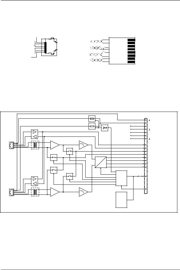
The following block diagram outlines the features once again. It shows a DPM 4000 equipped with a 2-channel paging station module (NRS 90215), a MIC/LINE + 2 AUX inputs module (NRS 90216), two 2-channel LINE output modules (NRS 90218) and an 8 I/O control module (NRS 90219). The ports of the interface block are standard. Their functioning is explained in detail on the following pages. The "Optional" port allows for retrofitting an additional serial port for the intercommunication between several DPM 4000s or connecting external devices / entire installations.
|
|
|
|
DPM 4000 |
|
|
|
|
|||||
|
|
|
|
|
|
|
|
|
|
|
|
|
|
|
IN A Pag. Console |
|
|
|
|
|
|
|
|
|
LINE OUT A |
|
|
|
|
|
|
|
|
|
|
|
|
|
|
||
|
|
|
|
|
|
|
|
|
|
|
|
||
|
|
|
|
|
|
|
|
|
|||||
|
SLOT 1 |
|
|
|
|
|
|
|
|
|
SLOT 3 |
|
|
|
|
|
|
|
|
|
|
|
|
|
|
||
|
|
|
|
|
|
|
|
|
|||||
|
NRS 90215 |
|
|
|
|
|
|
|
|
|
NRS 90218 |
|
|
|
|
|
|
|
|
|
|
|
|||||
|
IN B Pag. Console |
|
AUDIO MATRIX 4x4 |
|
LINE OUT B |
|
|
||||||
|
|
|
|
|
|
|
|||||||
|
|
|
INPUT FILTERS |
|
|
|
|
||||||
|
|
|
|
|
|
|
|||||||
|
|
|
OUTPUT DELAYS |
|
|
|
|
||||||
|
AUX1 |
|
CHIME / ALARM |
|
|
|
|
||||||
|
|
SIGNAL GENERATOR |
|
|
|
|
|||||||
|
IN A |
|
MESSAGE RECORDER |
|
LINE OUT A |
|
|
||||||
|
AUX2 |
|
SYSTEM TIMER |
|
|
|
|
||||||
|
|
|
|
|
|
||||||||
|
|
|
|
|
|
|
|||||||
|
SLOT 2 |
|
|
CALENDAR |
|
SLOT 4 |
|
|
|||||
|
NRS 90216 |
|
CONTROL / SUPERVISION |
|
NRS 90218 |
|
|
||||||
|
|
|
|
|
|
|
|||||||
|
|
|
POWER MANAGEMENT |
|
|
|
|
||||||
|
IN B MIC / LINE |
|
|
|
|
|
|
|
|
|
LINE OUT B |
|
|
|
|
|
|
|
|
|
|
|
|
|
|
|
|
+ DC INPUT |
|
|
|
|
|||
|
|
|
|
||||
|
|
|
24V = |
INTERFACE |
|
OPTION PORT |
|
|
|
|
|
||||
|
|
RS-232 PC INTERFACE |
|
|
|
||
|
|
|
+ 24V = |
|
|||
|
|
|
|||||
|
|
|
|||||
|
|
DCF 77 |
|
|
READY |
|
|
|
|
|
|
||||
|
|
|
|
||||
|
|
INP 1 |
|
REMOTE CONTROL |
|
||
|
|
|
|
||||
|
|
|
|
||||
|
|
INP 2 |
|
|
MONITOR OUT |
|
|
|
|
|
|
||||
|
|
|
|
||||
|
IN 1 |
|
|
|
|
|
|
|
|
IN 2 |
|
|
|
|
|
IN 3 |
|
|
|
|
|
|
|
|
IN 4 |
SLOT 5 |
|
||
|
||
|
IN 5 |
NRS 90219 |
|
||
|
IN 6 |
|
|
|
|
|
|
|
|
IN 7 |
|
|
|
|
|
|
|
|
IN 8 |
|
|
|
|
|
|
SLAVE CLOCK OUT 1  OUT 2
OUT 2  OUT 3
OUT 3  OUT 4
OUT 4  OUT 5
OUT 5  OUT 6
OUT 6  OUT 7
OUT 7  OUT 8
OUT 8 
figure 5.1 DPM 4000 block diagram
5-2 |
PROANNOUNCE System User Handbook 1.1 |
DEVICE DESCRIPTIONS
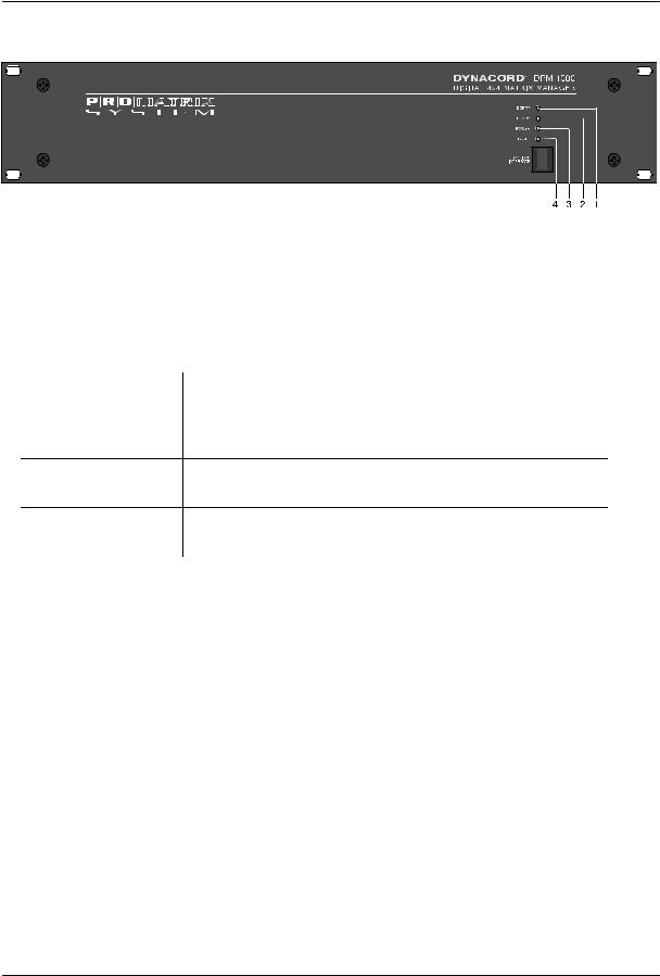
5.1.2 Front View
figure 5.2 DPM 4000 front view
The following controls and indicators are located on the DPM 4000's front panel:
1.LED DCF 77
This LED indicates the operation mode of the DCF 77 radio-controlled-signal receiver. The following table shows the different indications and explains their corresponding status:
LED indication |
status |
OFF |
No radio control signal detected or no DCF 77 antenna connected. The |
|
system clock is quartz-synchronized. |
ON |
The radio control signal is received. The system clock is synchronized |
|
to the DCF 77 signal. |
Blinking, one cycle per The radio control signal is present and the system clock is being second synchronized. This procedure can take up to 2 minutes. After
synchronization is complete, the DCF 77 LED light continuously.
Blinking, fast |
The radio control signal is detected but its reception is jammed. Re- |
|
adjusting the DCF 77 antenna or choosing a location with improved |
|
reception is recommended. |
2.LED READY
This LED indicates the operation mode of the PROANNOUNCE System. After switching the power on, the READY LED blinks while the system boots. Depending on the complexity of the installation blinking can take several seconds. After successful initialization, the LED lights, signaling that the system is ready for operation. Whenever erroneous operation – either in the DPM 4000 or in one of the connected components – is detected, the LED goes out indicating that a system error occurred. When the system power is OFF, the READY LED is OFF as well.
3.LED POWER
This LED lights as soon as a power source (24 V =, power supply or battery) is connected to the DPM 4000. The LED does not light when the DPM 4000's power supply is disconnected, switched off or fails.
4.LED FAULT
This LED lights during a reset or when an internal watchdog error is being detected within the DPM 4000. It also indicates erroneous operation of external system components (power amplifiers, paging stations, relay boards, ...). The LED is connected to the READY relay on the rear of the appliance, which allows remote indication of system errors.
PROANNOUNCE System User Handbook 1.1 |
5-3 |
DEVICE DESCRIPTIONS
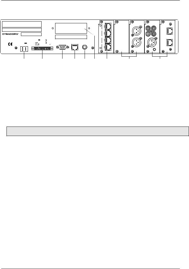
5.1.3 Rear View
WARNING: TO REDUCE THE RISK OF FIRE OR ELECTRIC SHOCK, DO NOT EXPOSE THIS APPLIANCE TO RAIN OR MOISTURE.
AVIS: RISQUÉ DE CHOC ELECTRIQUE. NE PAS OUVRIR.
NO USER SERVICEABLE PARTS INSIDE. REFER SERVICING TO
QUALIFIED SERVICE PERSONNEL.
121619 |
|
|
|
|
|
DPM 4000 |
|
SIGNAL INTERFACE |
|||
MADE IN GERMANY |
1 |
+ 24V |
6 |
INP 1 |
|
DC INPUT |
2 |
GROUND |
7 |
||
|
|||||
24 |
3 |
READY |
8 |
INP 2 |
|
9 |
|||||
+ -- |
4 |
|
10 DCF 77 |
||
5 |
|
||||
|
11 DCF 77 IN |
||||
|
|
||||
|
1 |
|
|
11 |
|
|
|
5 |
|
DPM - LC 8 4 |
3 |
DPM - OUT 2 |
|
DPM - MLA 1 |
DPM - PCI |
|
|
|
|
8 |
|
|
|
|
|
|
|
|
|
|
|
|
|
AUX |
DPC 4000 IN |
|
|
|
|
5 |
|
|
|
|
|
|
|
|
|
|
|
|
IN 1 |
|
|
|
|
|
|
OUT |
|
|
|
|
|
|
|
|
|
A |
A |
|
|
A |
|
|
|
|
C |
4 |
|
|
|||
|
|
|
|
|
LINE |
|
AUX |
|
|
|
|
|
O |
|
|
|
|
||
|
|
|
NU 1 |
|
OUT |
|
IN 2 |
|
|
CAUTION: SEE OPERATION MANUAL FOR MODULE |
N |
|
0/+6 dBu |
L |
R |
|
|||
T |
|
|
|
|
|||||
FITTING AND CORRECT CABLES AND CONNECTION. |
R |
8 |
|
|
|
|
DPC 4000 IN |
||
|
|
|
O |
|
|
|
|
|
|
RS-232 |
REMOTE |
MONITOR OUT |
L |
5 |
B |
B |
|
|
B |
PC INTERFACE |
CONTROL |
8 OHMS 1 WATT |
|
|
|
||||
|
|
PHONES |
|
IN |
|
LINE |
|
MIC/ |
|
|
|
|
|
4 |
|
|
|
||
|
|
|
|
|
OUT |
|
LINE |
|
|
|
|
|
|
|
|
0/+6 dBu |
|
IN |
|
|
|
|
|
1 |
|
|
|
GAIN |
|
|
|
|
|
90219 |
|
90218 |
|
90216 |
90215 |
1 |
2 |
3 |
4 |
5 |
6 |
7 |
8 |
9 |
figure 5.3 DPM 4000 rear view
The following module ports and connections are located on the rear panel of the DPM 4000:
1.DC INPUT 24V ==
The DPM 4000's power supply source has to be connected here; a 24 VDC power supply or a PROANNOUNCE system battery module using insulated AMP flat-connector plugs 6.3 x 0.8 mm. The DPM 4000 is protected against polarization mismatch and all positive and negative conductors within the device are fuse-protected. The fuses are located inside the enclosure on the printed board assembly 80430. The connection cables have to be 1,5 mm2 in diameter at least. With this diameter the cable length of a single path should not exceed 4.0 m (max. drop in voltage <1V).
CAUTION: Using the DPM 4000 is only permissible with batteries that are not grounded or provide a grounded negative pole. Operation with grounded positive pole is not admissible.
2.SIGNAL INTERFACE
Signal |
Pins |
Description |
+24V == |
1 |
24 V== voltage output for the supply of external components. The maximum current |
|
|
handling capacity is 400 mA. |
GROUND |
2 |
Ground connector of the 24 V== voltage output. |
READY |
3, 4, 5 |
Floating output for the indication of the system's operation mode. In the normal ready |
|
|
mode the READY relay is activated. When internal errors occur or external devices |
|
|
show faulty behavior, the READY-relay drops. The relay is connected to the FAULT |
|
|
LED indicator on the front panel of the DPM 4000 providing indication of the |
|
|
operational status directly on the appliance. |
INP1 |
6, 7 |
Floating input for monitoring / remote controlling the battery power supply, usually |
|
|
connected to a battery module or battery charging unit. Since this input can be freely |
|
|
programmed, using it for any other 24 V control signal is possible as well. |
INP2 |
8, 9 |
Floating input for monitoring / remotely controlling the power supply, usually |
|
|
connected to the 24 V== system power supply. Since this input can be freely |
|
|
programmed, using it for any other 24 V control signal is possible as well. |
DCF77 |
10, 11 |
Socket for connecting an external DCF 77 antenna. This input provides the supply |
|
|
voltage and simultaneously serves as input for the decoded DCF 77 signal. Only |
|
|
connecting the NRS 90193 DCF 77 receiver is admissible while polarity is not a |
|
|
critical factor. However, according to CE regulations, shielded cabling has to be used. |
|
|
Connect the shield to the connector's pin 10 and the signal line to pin 11. |
5-4 |
PROANNOUNCE System User Handbook 1.1 |
DEVICE DESCRIPTIONS
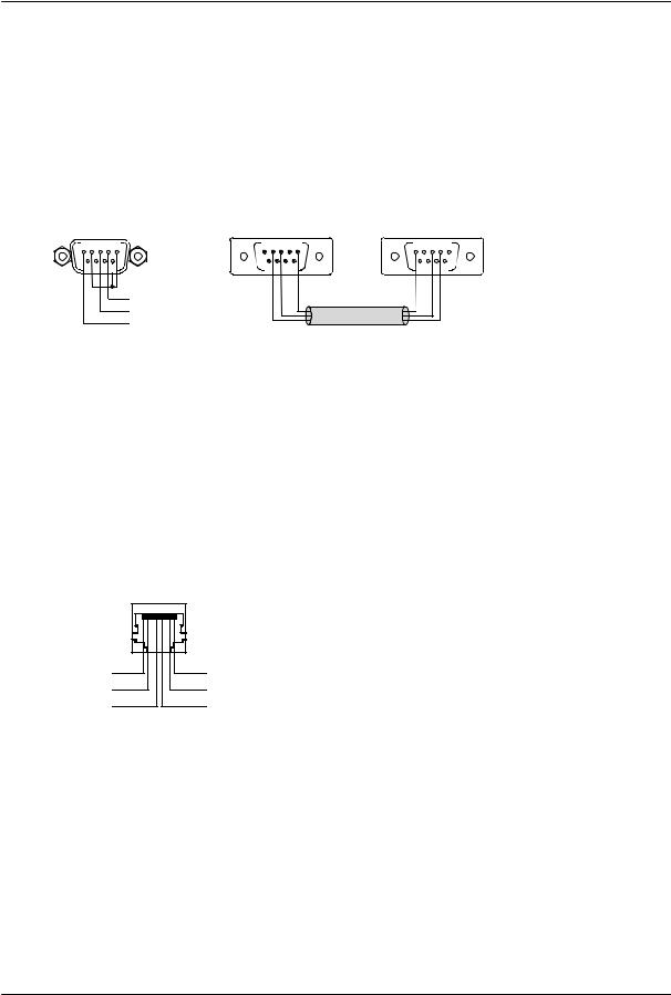
3.RS-232 PC INTERFACE
This 9-pole PC-interface is meant for connecting a computer (female, pin 4 = TXD, pin 3 = RXD, pin 1 = ground). It is used to transfer data between the PC and the DPM 4000 during system configuration as well as for control, monitoring, and remote diagnosis purposes. The PC is connected to the DPM 4000 utilizing a standard 1:1 D-sub extension cord with male connectors on one end and female connectors on the other.
As an alternative to the RS-232 port, an optical IrDA interface is provided on the front panel of the appliance offering the possibility for wireless data transmission.
RS-232
PC INTERFACE
5 4 3 2 1 |
9 8 7 6 |
TxD |
RxD |
MASSE |
RS-232 extension cord
1 2 3 4 5 |
5 4 3 2 1 |
6 7 8 9 |
9 8 7 6 |
figure 5.4 pin-assignment of the RS-232 PC INTERFACE connector, D-Sub extension cord
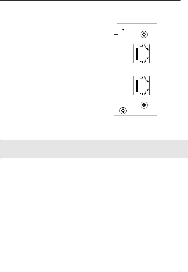
4.REMOTE CONTROL socket
This 8-pole RJ-45-type socket is meant for connecting DCS 401 control modules or DPA 4000 power amplifiers with remote interface. The connector provides a RS-485 interface for communicating with control modules and power amplifiers (pins 4 / 5), a balanced audio input for the insertion of external monitor signals (pins 7 / 8), and a 24 V== supply voltage output for the supply of external modules (pin 1 = +24 V, 1 A max., pin 2 = GND). A programmable electronic fuse (adjustable to 330 mA, 660 mA, 990 mA) protects the voltage output against short-circuit and overload. External devices are connected through common RJ-45 extension cords. For additional information, please refer to the corresponding chapters of the individual device.
REMOTE |
|
CONTROL |
|
1 |
8 |
+ 24V |
|
GND |
|
RS-485 + |
|
AUDIO IN - AUDIO IN + RS-485 -
figure 5.5 pin-assignment of the REMOTE CONTROL socket
The RS-485 bus may not exceed a maximum length of 1,000m and must follow a line-structure (short stub cables are permissible). Cabling has to be carried out using twisted pair cables (38.400 Bd, 8N1)
PROANNOUNCE System User Handbook 1.1 |
5-5 |
DEVICE DESCRIPTIONS
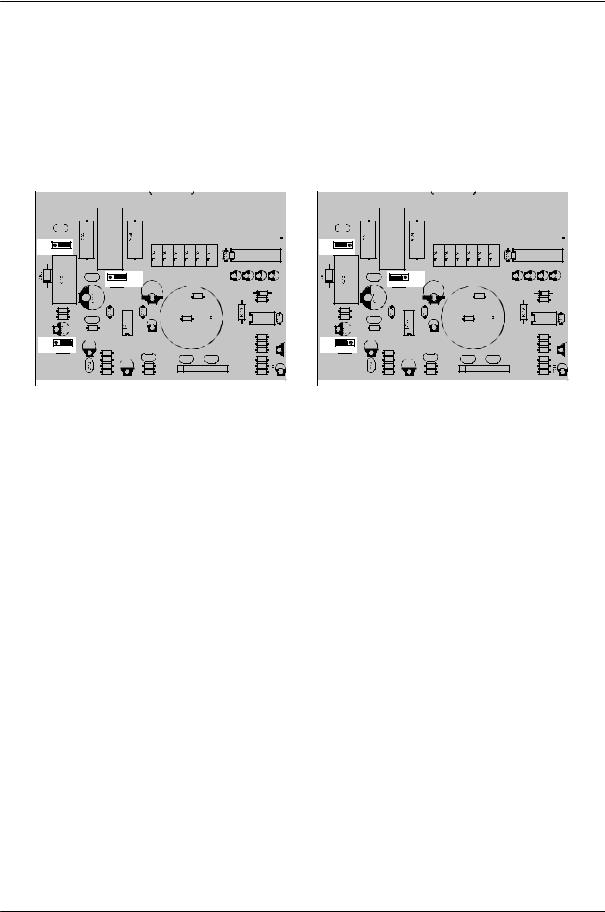
5.MONITOR OUTPUT socket
The audio signal of the integrated monitor amplifier is outputted via this connector. In standard configuration, this output is set for the connection of headphones. It is also possible to directly connect a loudspeaker with minimum load impedance of 8 Ohms. To achieve higher output capacity it is possible to set the internal monitor amplifier to bridged operation. Thus some internal jumpers have to be re-set as shown in the figure below.
jumper-setting for headphones operation |
|
|
jumper-setting for bridged operation |
|
|
|
|
|
|
|
|||||||||||||||||||||||||||||||||||||||||||
Jumper-Einstellung für Kopfhörerbetrieb |
|
|
Jumper-Einstellung für Brückenbetrieb |
|
|
|
|||||||||||||||||||||||||||||||||||||||||||||||
|
|
|
|
|
|
|
|
|
|
|
|
|
|
|
|
|
|
|
|
|
|
|
|
|
|
|
|
|
|
|
|
|
|
|
|
|
|
|
|
|
|
|
|
|
|
|
|
|
|
|
|
|
|
|
|
|
|
|
|
|
|
|
|
|
|
8 |
1 |
|
|
|
|
|
|
|
|
|
|
|
|
|
|
|
|
|
|
|
|
|
|
|
|
8 |
1 |
|
|
|
|
|
|
|
|
|
|
|
|
|
|
|
|
|
|
|
|
|
|
|
|
|
|
|
|
|
|
|
|
|
|
|
|
|
|
|
|
|
|
|
|
|
|||||||||||||||||||||||
|
|
|
|
|
|
|
|
|
|
|
|
|
CN101 |
|
|
|
|
|
|
|
|
|
|
|
|
|
|
|
|
|
|
|
|
|
|
|
|
|
|
CN101 |
|
|
|
|
|
|
|
|
|
|
|
|
|
|
|
|
|
|
|
|
|
|
|
|
|
|
|
|
|
|
|
CN201 |
|
|
|
|
|
|
|
|
|
|
|
|
|
|
|
|
|
|
|
|
|
|
|
CN201 |
|
|
|
|
|||||||
|
|
|
|
|
|
|
|
|
|
|
|
|
|
|
|
|
|
|
|
|
|
|
|
|
|
|
|
|
|
|
|
|
|
|
|
|
|
|
|
|
|
|
|
|
|
||||||||
|
|
|
|
|
|
|
|
|
|
|
|
|
|
|
|
|
|
6 |
9 |
|
|
|
|
|
|
|
|
|
|
|
|
|
|
|
|
|
|
|
|
|
|
|
6 |
9 |
|
|
|
|
|||||
|
|
|
|
|
|
|
|
|
|
|
|
|
|
|
|
|
|
1 |
5 |
|
|
|
|
|
|
|
|
|
|
|
|
|
|
|
|
|
|
|
|
|
|
|
1 |
5 |
|
|
|
|
|||||
|
|
|
|
|
|
|
|
|
|
|
|
|
|
|
|
|
|
|
|
|
|
|
|
|
|
|
|
|
|
|
|
|
|
|
|
|
|
|
|
|
|
|
|
|
|||||||||
|
|
|
|
|
|
|
|
|
|
|
|
|
|
|
|
|
|
|
|
|
|
|
|
|
|
|
|
|
|
|
|
||||||||||||||||||||||
|
C142 |
|
|
|
|
|
|
|
|
|
|
|
|
|
|
|
|
C142 |
|
|
|
|
|
|
|
|
|
|
|
|
|
|
|
||||||||||||||||||||
|
|
|
|
|
|
|
|
|
|
|
|
|
|
|
|
|
|
|
|
|
|
|
|
|
|
|
|
||||||||||||||||||||||||||
|
|
|
|
|
|
|
JS101 |
|
|
|
|
|
|
FL201 |
|
|
FL202 |
|
|
|
|
|
|
|
|
|
|
|
JS101 |
|
|
|
|
|
|
FL201 |
|
|
FL202 |
|
|
|
|
||||||||||
JP101 |
|
|
|
|
|
|
|
|
JP101 |
|
|
|
|
|
|
|
|
3 |
2 |
1 |
|
|
IC201 |
|
|
|
3 |
2 |
1 |
|
|
IC201 |
|
|
|
|
|
|
|
|
C203 |
C201 |
C202 |
C204 |
|
|
|
|
|
C203 |
C201 |
C202 |
C204 |
|
|
C141 |
|
|
JP103 |
|
|
|
|
|
C141 |
|
|
JP103 |
|
|
|
|
|
3 |
2 |
1 |
C139 |
|
D204 |
|
|
|
3 |
2 |
1 |
C139 |
|
D204 |
|
|
|
|
|
|
|
|
|
|
|
|
|
|
|
|
|
||
|
|
|
|
|
R101 |
|
R211 |
|
|
|
|
|
|
R101 |
|
R211 |
|
|
|
|
|
|
|
|
|
|
|
|
|
|
|
|
|
||
|
R122 |
|
|
|
|
|
|
|
|
R122 |
|
|
|
|
|
|
|
|
R121 |
C115 |
|
|
R102 |
|
IC204 |
|
|
R121 |
C115 |
|
|
R102 |
|
IC204 |
|
|
|
|
|
|
|
|
|
|
|
|
|
|
|
|
|
||
|
|
R120 |
|
|
|
|
|
|
|
|
R120 |
|
|
|
|
|
|
|
|
|
|
C140 |
T101 |
|
R213 |
|
|
|
|
C140 |
T101 |
|
R213 |
|
|
|
|
|
|
|
|
|
|
|
|
|
|
||
JP102 |
|
|
C113 |
|
|
|
R212 |
JP102 |
|
|
C113 |
|
|
|
R212 |
3 |
2 |
1 |
|
|
|
R210 |
3 |
2 |
1 |
|
|
|
R210 |
||
R118 |
|
|
|
R118 |
|
|
|
||||||||
|
|
|
C108 |
|
|
|
|
|
|
C108 |
|
|
|
||
|
|
|
R117 |
C101 |
C102 |
R216 |
|
|
|
R117 |
C101 |
C102 |
R216 |
R110 |
C110 |
R107 |
RN101 |
R227 |
R110 |
C110 |
R107 |
RN101 |
R227 |
R114 |
|
R108 |
R228 |
R114 |
|
R108 |
R228 |
||
|
|
|
|
figure 5.6 adjusting the monitor amplifier's output power via jumpers on the printed board assembly 80430
6.Extension slot
The DPM 4000 extension slot allows retrofitting additional serial ports, which can be used for the intercommunication amongst DPM 4000 managers or to connect additional external devices. For detailed information, please refer to the owner’s manuals of the individual extensions or modules.
7.Control Module Slot
Slot 5 is a control slot, which can be equipped with control modules for general control and query purposes. Control modules provide different kinds of control inputs and outputs. For detailed description, please refer to the following chapters. The DPM 4000 is shipped with one 8 I/O control module installed.
8.Slots for Audio Output Modules
The slots 3 and 4 are the DPM 4000's audio output slots providing two audio outputs per slot. Each slot can be equipped with a 2-channel audio output module. The DPM 4000 is shipped with a 2-channel audio output module installed in slot 3; described in detail at a later stage. Slot 4 is empty.
9.Audio Input Module Slots
The slots 1 and 2 are the DPM 4000's audio input module slots providing two audio inputs per slot. Each slot can be equipped with any suitable audio input module. A detailed description of available audio input modules can be found in the following chapters. The DPM 4000 is shipped with no audio input modules installed.
5-6 |
PROANNOUNCE System User Handbook 1.1 |
5.1.4 Specifications
Supply voltage
Nominal power consumption Maximum power consumption
Audio section
Inputs
Outputs
Frequency Response
S/N ratio
Distortion
24 V output Ready output Logic inputs
Voltage with input OFF (LOW) Voltage with input ON (HIGH) Maximum input voltage
DCF77 input
RS-232 interface
Remote interface Serial port Supply output
Supply voltage Nominal current
Monitor input
Nominal input level Max. input level Input balance
Monitor output
Output level
Output power handling
Operating temperature range
Dimensions W x H x D
Installation depth
Weight
Optionally available extensions
DEVICE DESCRIPTIONS
24 V DC (21.6 ... 31.2 V DC)
500 mA
6.7 A
see specifications of the corresponding input module see specifications of the corresponding output module 20 Hz ... 20 kHz, 0.5 dB
> 100 dB (A-weighted) < 0.01 %
24 V DC / 400 mA max. (21.6 ... 31.2 V DC) floating relay contacts, 1 A / 24 V DC
2, floating via opto-coupler, bi-pole UIN < 5 V
UIN > 10 V UIN max = 31 V
2-pole, for the NRS 90193, DCF 77 receiver
19,200 Baud, 8 data bits, 1 stop bit, no parity, Xon/Xoff
RS-485 standard
short-circuit-proof, electronically programmable fuse 24 V DC (21.6 ... 31.2 V DC)
330 mA, 660 mA, 990 mA (selectable, electronic fuse) electronically balanced, transformer optionally available +2.2 dBu / 1 V
+10 dBu / 2.5 V > -30 dB
6.3 mm phone jack, either for the connection of headphones or speakers
with headphones: |
650 mV / -1.5 dBu |
with loudspeakers: |
1.8 V / 7.2 dBu |
with headphones: |
50 mW / 8 |
with loudspeakers: |
380 mW / 8 |
+5 C ... +40 C
19“, 2 HE 483 x 88 x 337 mm
340 mm (410 mm incl. connectors)
6.4 kg
NRS 90208 input transformer for 1 monitor input, order no. 121 641
PROANNOUNCE System User Handbook 1.1 |
5-7 |
DEVICE DESCRIPTIONS
5.1.5 2-Channel Paging Station Module (NRS 90215)
This 2-channel audio input module is meant for the connection of DPC 4000 Series paging consoles. Each of the two input channels provide RJ-45 sockets allowing the connection of up to 4 paging stations plus paging station extensions per input. The microphone terminals are interconnected via 6-conductor parallel cables. The module can be installed in slot 1 and slot 2.
Next to the electronically balanced audio input, each input connector provides a serial RS-485 interface port and the power supply connection for the paging stations (see also: pin-assignment of the RJ-45 connector). The paging stations' power supply employs an electronic, programmable fuse, through which the maximum output current can be matched to meet actual system accommodations. This prevents the entire installation from malfunction, in case of short-circuit occurring in a single paging station only.
Input channels can be switched separately onto the monitor bus and you can monitor the audio signal via headphones or loudspeaker, either which is connected to the monitor output. Automatic pilot tone surveillance of the entire input stage is integrated as well. If necessary, retrofitting the audio inputs with transformers is possible.

 DPM - PCI
DPC 4000 IN
A
DPC 4000 IN
B
90215
figure 5.7 2-channel paging station module
Note: When connecting several paging consoles to a single input, please keep in mind that line interruption or short-circuit can cause malfunction of several or even all paging stations of that specific line. In emergency alert installation, connecting security-related consoles to individual inputs is therefore of major importance.
Specifications:
description |
DPM-PCI 2-channel paging station module, NRS 90215 |
connections |
2 x RJ-45 sockets |
audio |
|
inputs |
2, electronically balanced, transformers are optionally available |
nominal input level |
0 dBu / 775 mV |
max. input level |
+12 dBu / 3 V |
input impedance |
20 k |
input balancing |
> -30 dB |
frequency response |
20 Hz ... 20 kHz, 0.5 dB |
S/N ratio |
> 100 dB (A-weighted) |
distortion |
< 0.01 % |
A/D-conversion |
18-bit linear, Sigma-Delta |
control interfaces |
2 x RS-485 standard |
power supply outputs for the DPC 4000 2, short-circuit-proof, electronically programmable fuses |
|
supply voltage |
24 V DC (21.6 ... 31.2 V DC) |
nominal current |
330 mA, 660 mA, 990 mA (adjustable, electronic fuse) |
power consumption |
2 W |
operational temperature range |
+5 C ... +40 C |
dimensions W x H x D |
37.5 x 81 x 248 mm |
weight |
152 g (220 g including 2 x NRS 90208) |
extensions |
NRS 90208 input transformer for 1 paging station input, order-No. 121 641 |
5-8 |
PROANNOUNCE System User Handbook 1.1 |
DEVICE DESCRIPTIONS
Pin-Assignment Of DPC 4000 Connectors And The Extension Cord:
Connecting DPC 4000 paging stations to the DPC 4000 IN connector is established through the use of common RJ-45 extension cords, where the conductors are twisted in pairs as follows: pair 1 = 1/2 (24 V/GND), pair 2 = 3/6 (free), pair 3 = 4/5 (RS-485), pair 4 = 7/8 (AUDIO).
AUDIO IN - |
DPC 4000 IN |
|
RJ45 |
extension |
cord |
|
8 |
|
|
|
|
||
AUDIO IN + |
AUDIO |
|
8 |
|
||
RS485 |
- |
|
|
7 |
|
|
RS485 |
+ |
|
RS-485 |
|
6 |
|
1 |
|
5 |
|
|||
GND |
|
|
|
4 |
|
|
+ 24V |
|
|
|
|
3 |
|
|
|
|
24V/GND |
|
2 |
|
|
|
|
|
1 |
|
|
figure 5.8 pin-assignment of the DPC 4000 connectors, RJ-45 extension cords
The RS-485 bus may not exceed a maximum length of 1,000m (mind the voltage drop for operation voltage) and must follow a line-structure (short stub cables are permissible). Twisted-pair wiring is of special importance.
Using IY(ST)Y wiring is allowable (38400 Bd, 9N1)
Block Diagram:
|
ELECTRONIC |
|
|
|
|
|
PROGRAMMABLE |
|
|
+U24 |
|
|
FUSES |
|
|
|
|
|
|
|
|
|
|
|
|
|
|
+12V |
ANALOG |
|
|
|
|
|
|
|
|
|
|
-12V |
SUPPLY |
|
|
|
|
|
|
DPC 4000 |
|
|
|
+5V |
DIGITAL |
IN A |
|
|
|
|
SUPPLY |
24V |
|
|
|
RX485 |
|
RS-485 |
|
|
|
|
|
AUDIO |
|
|
|
TX485 |
|
|
|
|
|
|
|
NRS 90208 |
|
|
|
INTERNAL MONITOR |
|
|
|
|
|
||
|
MON A |
|
|
PILOT |
|
|
|
|
|
|
|
|
A |
|
|
MCLK |
|
PILOT A |
|
|
BCLK |
2 CHANNEL |
|
|
|
|
|
WCLK |
DIGITAL |
|
D |
|
|
AUDIO |
|
|
|
|
|
DIN |
|
PILOT B |
|
|
|
|
|
|
|
BOARD |
4 |
SPI |
|
|
|
|
|
||
|
MON B |
|
|
|
|
|
CONTROL |
|
|
|
|
DPC 4000 |
|
|
|
|
|
IN B |
|
|
|
|
|
24V |
|
|
|
RES |
|
|
|
|
|
|
|
RS-485 |
|
|
|
|
|
AUDIO |
|
|
|
|
|
NRS 90208 |
|
BOARD |
|
|
|
|
|
STATUS |
|
|
|
|
|
& ID |
|
|
|
figure 5.9 block diagram 2-channel paging station module
PROANNOUNCE System User Handbook 1.1 |
5-9 |
DEVICE DESCRIPTIONS
Retrofitting Input Transformers:
In case galvanic separation of the audio signal is necessary, the module is prepared for retrofitting two input transformers. Separate NRS 90208 extensions consisting of audio transformer and insulation plate each are needed per input channel.
When retrofitting the transformers, please proceed as follows:
1.Disconnect the DPM 4000 from the mains power supply.
2.Loosen the two locking screws and carefully slide the module out of the slot.
3.Remove the two resistors of the corresponding input channel (IN A: R6 / R7, IN B: R3 / R8).
4.Place the insulation plate between the transformer and the printed board assembly and solder the transformer to position T1 for IN A or to position T2 for IN B.
5.Re-insert the module into the slot and carefully push it into the DPM 4000 until it firmly locks in place.
6.Fix the module in place using the two locking screws and reconnect the power supply.
|
|
|
|
|
|
|
|
|
|
|
|
|
|
|
|
|
|
|
|
|
|
|
|
|
|
|
|
|
|
|
|
|
|
|
|
|
|
|
|
|
|
|
|
|
|
|
|
|
|
|
|
|
|
|
|
|
|
|
|
|
|
|
|
|
|
|
|
|
|
|
|
|
|
|
|
|
|
|
|
|
|
|
|
|
|
|
|
|
|
|
|
|
|
|
|
|
|
|
|
|
|
|
|
|
|
|
|
|
|
|
|
|
|
|
|
|
|
|
|
|
|
|
|
|
|
|
|
|
|
|
|
|
|
|
|
|
|
|
|
|
|
|
|
|
|
|
|
|
|
|
|
|
|
|
|
|
|
|
|
|
|
|
|
|
|
|
|
|
|
|
|
|
|
|
|
|
|
|
|
|
|
|
|
|
|
|
|
|
|
|
|
|
|
|
|
|
|
|
|
|
|
|
|
|
|
|
|
|
|
|
|
|
|
|
|
|
|
|
|
|
|
|
|
|
|
|
|
|
|
|
|
|
|
|
|
|
|
|
|
|
|
|
|
|
|
|
|
|
|
|
|
|
|
|
|
|
|
|
|
|
|
|
|
|
|
|
|
|
|
|
|
|
|
|
|
|
|
|
|
|
|
|
|
|
|
|
|
|
|
|
|
|
|
|
|
|
|
|
|
|
|
|
|
|
|
|
|
|
|
|
|
|
|
|
|
|
|
|
|
|
|
|
|
|
|
|
|
|
|
|
|
|
|
|
|
|
|
|
|
|
|
|
|
|
|
|
|
|
|
|
|
|
|
|
|
|
|
|
|
|
|
|
|
|
|
|
|
|
|
|
|
|
|
|
|
|
|
|
|
|
|
|
|
|
|
|
|
|
|
|
|
|
|
|
|
|
|
|
|
|
|
|
|
|
|
|
|
|
|
|
|
|
|
|
|
|
|
|
|
|
|
|
|
|
|
|
|
|
|
|
|
|
|
|
|
|
|
|
|
|
|
|
|
|
|
|
|
|
|
|
|
|
|
|
|
|
|
|
|
|
|
|
|
|
|
|
|
|
|
|
|
|
|
|
|
|
|
|
|
|
|
|
|
|
|
|
|
|
|
|
|
|
|
|
|
|
|
|
|
|
|
|
|
|
|
|
|
|
|
|
|
|
|
|
|
|
|
|
|
|
|
|
|
|
|
|
|
|
|
|
|
|
|
|
|
|
|
|
|
|
|
|
|
|
|
|
|
|
|
|
|
|
|
|
|
|
|
|
|
|
|
|
|
|
|
|
|
|
|
|
|
|
|
|
|
|
|
|
|
|
|
|
|
|
|
|
|
|
|
|
|
|
|
|
|
|
|
|
|
|
|
|
|
|
|
|
|
|
|
|
|
|
|
|
|
|
|
|
|
|
|
|
|
|
|
|
|
|
|
|
|
|
|
|
|
|
|
|
|
|
|
|
|
|
|
|
|
|
|
|
|
|
|
|
|
|
|
|
|
|
|
|
|
|
|
|
|
|
|
|
|
|
|
|
|
|
|
|
|
|
|
|
|
|
|
|
|
|
|
|
|
|
|
|
|
|
|
|
|
|
|
|
|
|
|
|
|
|
|
|
|
|
|
|
|
|
|
|
|
|
|
|
|
|
|
|
|
|
|
|
|
|
|
|
|
|
|
|
|
|
|
|
|
|
|
|
|
|
|
|
|
|
|
|
|
|
|
|
|
|
|
|
|
|
|
|
|
|
|
|
|
|
|
|
|
|
|
|
|
figure 5.10 |
|
|
|
|
|
|
|
|
|
|
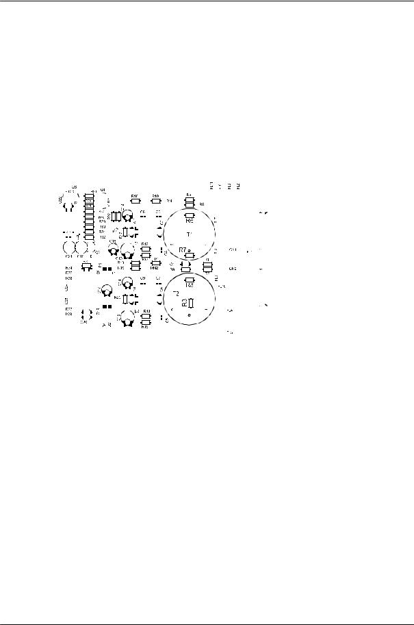
retrofitting the input transformers, location of parts (NRS 90215) |
||||||||||||||
5-10 |
PROANNOUNCE System User Handbook 1.1 |
DEVICE DESCRIPTIONS
5.1.6 MIC/LINE + 2 AUX Input Module (NRS 90216)
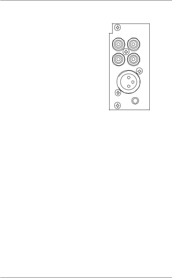
This 2-channel audio input module is meant for the connection of external audio sources of any kind. Channel A employs two switched AUX-inputs with 4 RCA-type connectors (2 x L / R) for CD players, tape decks, tuners, DAT decks, etc. The MIC / LINE-input of channel B is provided through an XLRF-type connector allowing the connection of microphones, mixers and other similar sources. The module can be inserted in slot 1 and slot 2.
Input levels of both AUX-inputs can be separately adjusted via internal potentiometers in a range between – 10 dBu to +12 dBu.
The MIC / LINE-input's sensitivity can also be adjusted through an internal MIC / LINE switch (PAD) providing 30 dB attenuation. The GAIN-control on the appliance's rear panel offers additional control within a range of 40 dB. The MIC / LINE input is electronically balanced and can be retrofitted with a transformer. Phantom power can be switched via a jumper. If necessary, it is also possible to incorporate a compressor / limiter into the audio path via jumper setting.
The input channels can be switched separately to the monitor bus and you can listen to the signal via headphones or loudspeaker, either which is being connected to the monitor output. Automatic pilot tone surveillance of the entire input stage is integrated as well.
|
DPM - MLA |
|
AUX |
|
IN 1 |
A |
|
|
AUX |
|
IN 2 |
L |
R |
B |
|
|
MIC/ |
|
LINE |
|
IN |
|
GAIN |
|
90216 |
figure 5.11 MIC/LINE + 2 AUX input module
Specifications:
description |
DPM-MLA MIC/LINE + 2 AUX input module, NRS 90216 |
||
connections |
1 x XLRF-type / 4 x RCA-type connectors |
||
input A |
2 x AUX, unbalanced, internally summed |
||
nominal input level |
-10 dBu ... +12 dBu / 250 mV ... 3 V |
||
max. input level |
+12 dBu / 3 V |
|
|
input impedance |
10 k |
|
|
input B |
MIC/LINE, electronically balanced, transformers are optionally available |
||
nominal input level |
MIC: |
-54 dBu ... -14 dBu / |
1.5 mV ... 155 mV |
|
LINE: |
-24 dBu ... +16 dBu / |
50 mV ... 5 V |
max. input level |
MIC: |
+5 dBu / 1.4 V |
|
(im limiter operation) |
LINE: |
+30 dBu / 25 V |
|
input impedance |
MIC: |
3.6 k |
|
|
LINE: |
10 k |
|
input balancing |
> -30 dB |
|
|
phantom power |
24V / 20 mA, switched via jumper |
||
audio |
|
|
|
frequency response |
20 Hz ... 20 kHz, 0.5 dB |
|
|
S/N ratio |
> 95 dB (A-weighted) |
|
|
distortion |
< 0.01 % |
|
|
A/D-conversion |
18-bit linear, Sigma-Delta |
|
|
power consumption |
2.3 W |
|
|
operational temperature range |
+5 C ... +40 C |
|
|
dimensions W x H x D |
37.5 x 81 x 252 mm |
|
|
weight |
160 g (173 g including NRS 90233) |
||
extensions |
NRS 90233 input transformer for 1 MIC/LINE input, order-No. 121 682 |
||
PROANNOUNCE System User Handbook 1.1 |
5-11 |
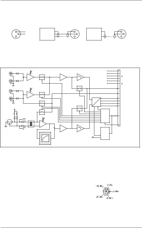
DEVICE DESCRIPTIONS
Pin-Assignment Of XLRF-Type Connectors:
The pin-assignment of the MIC/LINE input's XLRF-type connector is as follows: pin 1 = screen, pin 2 = positive conductor, pin 3 = negative conductor. In unbalanced configuration, the pins 3 (-) and 1 (screen) have to be bridged inside the connection plug.
1 |
SHIELD |
BALANCED |
LO (-) |
1 |
UNBALANCED |
1 |
3 |
-- |
|
|
|
3 |
3 |
2 |
+ |
SOURCE |
HI (+) |
2 |
SOURCE |
2 |
MIC/ |
|
|
|
|
|
|
|
|
|
|
|
|
|
LINE |
|
|
|
|
|
|
IN |
|
|
|
|
|
|
figure 5.12 |
|
pin-assignment of the MIC/LINE IN XLRF-type connector |
|
|||
Block diagram:
|
|
|
|
AUX 1 |
|
|
|
|
+24V |
|
L |
|
|
|
|
|
|
|
+12V |
|
|
|
|
|
GAIN |
|
|
|
|
ANALOG |
||
AUX 1 |
|
|
|
|
|
|
|
|
|
SUPPLY |
|
|
|
|
|
|
|
|
-12V |
|
|
|
|
|
|
|
AUX 1 |
|
|
|
|
|
|
|
|
|
|
|
|
|
|
|
|
R |
|
|
|
|
|
|
|
|
+5V |
DIGITAL |
|
|
|
|
|
|
|
|
|
|
SUPPLY |
IN A |
|
|
|
|
|
|
|
|
INTERNAL MONITOR |
|
|
|
|
|
AUX 2 |
|
|
|
|
||
L |
|
|
|
MON A |
|
|
|
|
|
|
|
|
|
GAIN |
|
|
|
|
|
||
|
|
|
|
|
|
|
|
|
||
AUX 2 |
|
|
|
|
|
|
|
|
PILOT |
|
|
|
|
|
|
|
|
|
|
|
|
|
|
|
|
|
AUX 2 |
|
|
|
|
|
R |
|
|
|
|
|
|
A |
|
MCLK |
|
|
|
|
|
|
|
|
|
BCLK |
2 CHANNEL |
|
|
|
|
|
|
|
|
|
|
WCLK |
DIGITAL |
|
|
|
|
|
PILOT A |
|
D |
|
AUDIO |
|
|
|
|
|
|
|
|
|
DIN |
|
|
|
|
|
|
|
|
|
|
|
|
|
|
|
|
+24V |
MON B |
|
|
|
|
|
|
|
|
|
|
|
|
|
|
|
|
|
|
|
JP1 |
1 |
3 |
PILOT B |
|
|
|
|
|
|
|
2 |
4 |
|
BOARD |
|
|
|
||
|
|
|
|
4 |
SPI |
|
||||
|
|
|
|
|
|
|
|
|||
MIC/ |
|
|
|
|
|
|
CONTROL |
|
|
|
|
|
|
|
|
|
|
|
|
||
|
|
|
MIC |
|
|
|
|
|
|
|
LINE |
|
|
|
GAIN |
|
|
|
|
|
|
|
|
|
LINE |
|
|
|
|
|
||
|
|
|
|
|
|
|
|
|
|
|
IN B |
1 |
2 |
|
|
|
|
|
|
|
|
|
3 |
|
|
|
|
|
|
|
|
|
|
|
|
|
|
|
|
|
|
RES |
|
|
|
|
|
NRS 90233 |
LIN |
|
|
|
|
|
|
|
|
|
JP2 |
|
|
|
|
|
|
|
|
|
|
|
COMP |
|
|
|
|
|
|
|
|
|
|
|
|
BOARD |
|
|
|
|
|
|
|
|
|
|
STATUS |
|
|
|
|
|
|
|
|
LINE JP1 |
& ID |
|
|
|
|
|
|
|
|
|
|
|
|
|
||
|
|
|
|
|
MIC 5 |
6 |
|
|
|
|
|
|
|
|
|
COMPRESSOR / |
|
|
|
|
|
|
|
|
|
|
LIMITER |
|
|
|
|
|
figure 5.13 |
block diagram MIC/LINE + 2 AUX input module |
Internal Settings:
1.AUX input sensitivity
The input levels can be set in a range of -10 dBu to +12 dBu using trimmers VR2 (AUX 1) and VR3 (AUX 2). The trim-potentiometers’ coarse scales are meant for your convenience, helping you in adjusting the levels.
Potentiometer setting |
Input level |
Left margin |
+12 dBu |
Center position |
-3 dBu |
Right margin |
-10 dBu |
2.MIC / LINE switching and sensitivity setting for the MIC / LINE input
The MIC / LINE input's internal PAD-switch (S1) allows switching the channels' sensitivity between microphone and line level (30 dB). The GAIN-control on the module's front panel is provided to precisely adjust the input sensitivity (range 40 dB).
5-12 |
PROANNOUNCE System User Handbook 1.1 |
 Loading...