


OWNER’S MANUAL
DRM 4000
8-IN-2 AUDIO MIXER & ROUTER

IMPORTANT SAFETY INSTRUCTIONS
The lightning flash with arrowhead symbol, within an equilateral triangle is intended to alert the user to the 
 presence of uninsulated “dangerous voltage” within the
  product’s enclosure that may be of sufficient magnitude to constitute a risk of electric shock to persons.
The exclamation point within an equilateral triangle is intended to alert the user to the presence of important operating and maintance (servicing) instructions in the literature accompanying the appliance.
1.Read these instructions.
2.Keep these instructions.
3.Heed all warnings.
4.Follow all instructions.
5.Do not use this apparatus near water.
6.Clean only with a dry cloth.
7.Do not block any of the ventilation openings.
Install in accordance with the manufacturer’s instructions.
8.Install only in rack with back cover.
9.Only use attachments/accessories specified by the manufacturer.
10.Refer all servicing to qualified service personnel. Servicing is required when the apparatus has been
damaged in any way, such as power-supply cord or plug is damaged, liquid has been spilled or objects have fallen into the apparatus, the apparatus has been exposed to rain or moisture, does not operate normally, or has
been dropped.
11.To completely disconnect mains power from this apparatus, the power supply cord must be unplugged
For US, CANADA and Japan only:
Do not defeat the safety purpose of the grounding-type plug. A grounding type plug has two blades and a third grounding prong. The wide blade or the third prong are provided for your safety. When the provided plug does not fit into your outlet, consult an electrican for replacement of the obsolete outlet.
IMPORTANT SERVICE INSTRUCTIONS
CAUTION: These servicing instructions are for use by qualified personnel only. To reduce the risk of electric shock, do not perform any servicing other than that contained in the Operating Instructions unless you are qualified to do so. Refer all servicing to qualified service personnel.
1.Security regulations as stated in the EN 60065 (VDE 0860) and the CSA E60065-00 have to be obeyed when servicing the appliance.
2.Use of a mains separator transformer is mandatory during maintenance while the appliance is opened, needs to be operated and is connected to the mains
3.Switch off the power before retrofitting any extensions, changing the mains voltage or the output voltage.
4.The minimum distance between parts carrying mains voltage and any accessible metal piece (metal enclosure), respectively between the mains poles has to be 3 mm and needs to be minded at all times.
The minimum distance between parts carrying mains voltage and any switches or breakers that are not connected to the mains (secondary parts) has to be 6 mm and needs to be minded at all times.
5.Replacing special components that are marked in the circuit diagram using the security symbol (Note) is only permissible when using original parts.
6.Altering the circuitry without prior consent or advice is not legitimate.
7.Any work security regulations that are applicable at the location where the appliance is being serviced have to be strictly obeyed. This applies also to any regulations about the work place itself.
8.All instructions concerning the handling of MOS - circuits have to be observed.
Note: |
SAFETY COMPONENT (HAS TO BE REPLACED WITH ORIGINAL PART ONLY) |
1-2
CONTENTS
TABLE OF CONTENTS |
PAGE |
SAFETY AND SERVICE INSTRUCTIONS . . . . . . . . . . . . . . . . . . . . . . . . . . . . . . . . . . 1-2 1. INTRODUCTION . . . . . . . . . . . . . . . . . . . . . . . . . . . . . . . . . . . . . . . . . . . . . . . . . . . . 1-4
1.1 DRM 4000 Characteristics . . . . . . . . . . . . . . . . . . . . . . . . . . . . . . . . . . . 1-4 1.2 Unpacking and Warranty . . . . . . . . . . . . . . . . . . . . . . . . . . . . . . . . . . . . 1-5
2. CONTROLS AND CONNECTIONS. . . . . . . . . . . . . . . . . . . . . . . . . . . . . . . . . . . . . . 2-1 2.1 Front Panel . . . . . . . . . . . . . . . . . . . . . . . . . . . . . . . . . . . . . . . . . . . . . . . 2-1 2.2 Rear Panel . . . . . . . . . . . . . . . . . . . . . . . . . . . . . . . . . . . . . . . . . . . . . . . 2-3
3. QUICK START . . . . . . . . . . . . . . . . . . . . . . . . . . . . . . . . . . . . . . . . . . . . . . . . . . . . . . 3-1 4. INSTALLATION AND CONNECTIONS . . . . . . . . . . . . . . . . . . . . . . . . . . . . . . . . . . . 4-1
4.1 General Notes. . . . . . . . . . . . . . . . . . . . . . . . . . . . . . . . . . . . . . . . . . . . . 4-1 4.2 Input Assignment . . . . . . . . . . . . . . . . . . . . . . . . . . . . . . . . . . . . . . . . . . 4-1 4.2.1 MIC/LINE Inputs. . . . . . . . . . . . . . . . . . . . . . . . . . . . . . . . . . . . . . . 4-1 4.2.2 AUX and MIX IN Inputs . . . . . . . . . . . . . . . . . . . . . . . . . . . . . . . . . 4-2 4.3 Output Assignment . . . . . . . . . . . . . . . . . . . . . . . . . . . . . . . . . . . . . . . . . 4-2 4.3.1 MASTER Outputs . . . . . . . . . . . . . . . . . . . . . . . . . . . . . . . . . . . . . 4-2 4.3.2 SEND Outputs . . . . . . . . . . . . . . . . . . . . . . . . . . . . . . . . . . . . . . . . 4-2 4.3.3 DIRECT OUTPUT . . . . . . . . . . . . . . . . . . . . . . . . . . . . . . . . . . . . . 4-2 4.4 Control Inputs . . . . . . . . . . . . . . . . . . . . . . . . . . . . . . . . . . . . . . . . . . 4-3 4.4.1 CONTROL INPUTS . . . . . . . . . . . . . . . . . . . . . . . . . . . . . . . . . . . . 4-3 4.4.2 External VCA-Control. . . . . . . . . . . . . . . . . . . . . . . . . . . . . . . . . . . 4-3
5. INITIAL OPERATION. . . . . . . . . . . . . . . . . . . . . . . . . . . . . . . . . . . . . . . . . . . . . . . . . 5-1
5.1 Power-On Operation. . . . . . . . . . . . . . . . . . . . . . . . . . . . . . . . . . . . . . . . 5-1 5.2 Level Settings . . . . . . . . . . . . . . . . . . . . . . . . . . . . . . . . . . . . . . . . . . . . . 5-1 5.2.1 Level Adjustment for MIC/LINE Inputs . . . . . . . . . . . . . . . . . . . . . 5-1 5.2.2 Level Adjustment for AUX Inputs. . . . . . . . . . . . . . . . . . . . . . . . . . 5-2
6. SPECIAL FEATURES OF THE DRM 4000 . . . . . . . . . . . . . . . . . . . . . . . . . . . . . . . 6-1 6.1 Using Ducking Control . . . . . . . . . . . . . . . . . . . . . . . . . . . . . . . . . . . . . . 6-2 6.2 Limiter Operation . . . . . . . . . . . . . . . . . . . . . . . . . . . . . . . . . . . . . . . . . . 6-2 6.3 Cascading Several Units via MIX IN and SEND . . . . . . . . . . . . . . . . . . 6-2 6.4 Using The Unit Together With The DPM 4000. . . . . . . . . . . . . . . . . . . . 6-3
7. SOFTWARE EDITOR DRM 4000 . . . . . . . . . . . . . . . . . . . . . . . . . . . . . . . . . . . . . . . 7-1 7.1 System Requirements . . . . . . . . . . . . . . . . . . . . . . . . . . . . . . . . . . . . . . 7-1 7.2 Installation Notes . . . . . . . . . . . . . . . . . . . . . . . . . . . . . . . . . . . . . . . . . . 7-1 7.3 PC - DRM 4000 Connection . . . . . . . . . . . . . . . . . . . . . . . . . . . . . . . . . . 7-1 7.4 Software Description. . . . . . . . . . . . . . . . . . . . . . . . . . . . . . . . . . . . . . . . 7-2
7.4.1 General . . . . . . . . . . . . . . . . . . . . . . . . . . . . . . . . . . . . . . . . . . . . . 7-2 7.4.2 Menus and the Toolbar . . . . . . . . . . . . . . . . . . . . . . . . . . . . . . . . . 7-2 7.4.3 Basic Configuration . . . . . . . . . . . . . . . . . . . . . . . . . . . . . . . . . . . . 7-3 7.4.4 Control Inputs. . . . . . . . . . . . . . . . . . . . . . . . . . . . . . . . . . . . . . . . . 7-5 7.4.5 Online Control / Status. . . . . . . . . . . . . . . . . . . . . . . . . . . . . . . . . . 7-6
8. CONFIGURING THE DRM 4000 . . . . . . . . . . . . . . . . . . . . . . . . . . . . . . . . . . . . . . . . 8-1 9. INTERNAL SETTINGS / EXTENSIONS . . . . . . . . . . . . . . . . . . . . . . . . . . . . . . . . . . 9-1
9.1 Internal Configuration Possibilities . . . . . . . . . . . . . . . . . . . . . . . . . . . . . 9-1 9.1.1 Lo Cut-Filter . . . . . . . . . . . . . . . . . . . . . . . . . . . . . . . . . . . . . . . . . . 9-2 9.1.2 DIRECT OUTPUTS . . . . . . . . . . . . . . . . . . . . . . . . . . . . . . . . . . . . 9-2 9.1.3 AUX Sensitivity Selection . . . . . . . . . . . . . . . . . . . . . . . . . . . . . . . 9-3 9.2 Limiter Settings . . . . . . . . . . . . . . . . . . . . . . . . . . . . . . . . . . . . . . . . . . . . 9-3 9.3 How to install Extensions . . . . . . . . . . . . . . . . . . . . . . . . . . . . . . . . . . . . 9-4 9.3.1 How to install the Input Transformer (NRS 90233) . . . . . . . . . . . . 9-4 9.3.2 How to install the Output Transformer (NRS 90227). . . . . . . . . . . 9-5 9.3.3 How to install Interface-Boards . . . . . . . . . . . . . . . . . . . . . . . . . . . 9-6
10. SPECIFICATIONS . . . . . . . . . . . . . . . . . . . . . . . . . . . . . . . . . . . . . . . . . . . . . . . . . . 10-1
10.1 Specifications . . . . . . . . . . . . . . . . . . . . . . . . . . . . . . . . . . . . . . . . . . . . 10-1 10.2 User Configuration . . . . . . . . . . . . . . . . . . . . . . . . . . . . . . . . . . . . . . . . 10-2 10.3 Block Diagram . . . . . . . . . . . . . . . . . . . . . . . . . . . . . . . . . . . . . . . . . . . 10-4 10.4 RS-232 Interface - Programmer’s Instructions. . . . . . . . . . . . . . . . . . . 10-5 10.5 Dimensions . . . . . . . . . . . . . . . . . . . . . . . . . . . . . . . . . . . . . . . . . . . . . . 10-7 10.5 Warranty . . . . . . . . . . . . . . . . . . . . . . . . . . . . . . . . . . . . . . . . . . . . . . . . 10-8
1-3

INTRODUCTION
1. INTRODUCTION
First of all, we like to thank you for and congratulate you on buying a DYNACORD DRM 4000 8-in-2 Audio Mixer & Router. To ensure optimal performance and to minimize the risk of damaging the appliance through erroneous operation, please make sure to read this owner’s manual carefully before operating the DRM 4000.
1.1 DRM 4000 CHARACTERISTICS
The DRM 4000 is a rack-mixer and/or audio signal router offering 8 audio inputs and 2 audio outputs. The inputs are divided into 4 MIC/LINE channels and 4 AUX channels. Each input channel can be freely assigned to either one or both output channels, offering Mono 2-Channel operation as well as Stereo operation modes.
The DRM 4000 can be used as a pre-mixer for the DPM 4000, expanding the amount of available input channels. DRM 4000 and DPM 4000 are linked via remote-interface. Priority functions, preset switching and routing are easy to configure and operate. The DRM 4000 Mixer & Router can also be used as stand-alone unit for simple sound reinforcement tasks, e.g. in a multimedia set-up, as well as for straightforward intercom installations.
Field of Application
∙Pre-mixer to the DPM 4000 for connecting several switchable audio signal sources and microphones with priority or mixing function
∙Mixer for sound reinforcement systems in conference rooms, multi-purpose halls, congregation halls, gastronomy, houses of worship, etc.
∙Straightforward calling systems with the ability for background music playback
Characteristics
∙4 MIC/LINE input channels: XLR, electronically balanced, transformer optionally available.
∙4 AUX input channels: each with 2 RCA-type connectors.
∙Volume and tone control (Lo/Hi) in all input channels.
∙Signal / Peak LEDs (green / red) for monitoring the input level in all input channels.
∙Input channels can be freely assigned to the output channels, controlled via control contacts, optional RS-232 interface or from the DPM 4000.
∙Direct outputs for all MIC/LINE and AUX-channels. Pre/Post internally configurable.
∙Frontal connections: 1 MIC/LINE input (XLR) and 1 AUX-input (2 x RCA-type) connected parallel to MIC/LINE1 and AUX1.
∙Priority control (ducking function) in the inputs MIC/LINE 1 and 2; controllable via external contacts, signal level with adjustable threshold (on the front) or via remote control, indicated via LED’s on the front panel.
∙Limiter in the inputs MIC/LINE 1 and 2 with internally selectable threshold.
∙2 audio outputs: XLR, electronically balanced, transformer optionally available.
∙Separate summing controls and LED-chains for both outputs.
∙VCA’s in both output channels. 2 VCA control inputs A / B for remotely controlling the volume setting via external potentiometer, also controllable via serial interface (PC, DPM 4000, media-control) or via control contacts.
∙Mix-input for external feeds / extension: 2 x RCA-type, unbalanced, with level control on the rear panel
∙Send-output for recording / extension: 2 x RCA-type, unbalanced.
∙Remote control via external contacts: 8 freely configurable control inputs for ducking MIC/LINE 1 and 2, Preset switching, routing, volume switching, mute.
∙Optional serial RS-232 interface for PC or media-control: Direct control of all routing possibilities, output level control, configuration and storing of presets and the preset switching.
1-4

INTRODUCTION
∙Optional serial RS-485 interface for connecting the DPM 4000: control of all routing possibilities, ducking control, preset switching via macros, output level control, configuration and storing of presets via Designer software.
∙24V power supply; optional mains adapter for 90 - 240 V AC mains supply.
∙Power-on delay: relay switching to prevent audible power-on / off switching noise.
∙Enclosure: 19" / 1HU.
This owner’s manual contains lots of valuable information about the DRM 4000. So please keep it at a safe place for further reference.
1.2 Unpacking and Warranty
Carefully open the packaging and take out the DRM 4000. Next to this owner’s manual, the appliance is shipped together with three Phoenix-type connectors and the warranty card. Please make sure that the warranty card has been completed. Only with a fully completed warranty certificate any possible warranty claims can be granted. The appliance comes with a 36 months warranty, which is valid starting with the date when you had received the device from your dealer. Please keep the warranty certificate, the original invoice and also the original packaging at a safe place for any eventual shipping.
1-5
CONTROLS AND CONNECTIONS
2. CONTROLS AND CONNECTIONS
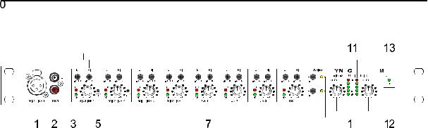
2.1 Front Panel
1, Socket MIC/LINE 1
Electronically balanced XLR-input on the front panel for the connection of microphones or other signal sources. This socket is connected parallel to the MIC/LINE 1 input on the appliance’s rear panel. Gain, Pad and phantom power settings have to be performed on the rear panel.
2, Sockets AUX 1 L/R
The AUX 1 L/R RCA-type connectors on the front panel allow connecting a 2-channel audio signal source (e.g. CD-Player). The connectors are connected parallel to the AUX 1 input on the appliance’s rear panel.
3, Signal/Peak-LED’s
The signal/peak-LED’s provide optical information about the momentary level of the corresponding input channel. When setting the input level, make sure that the signal-LED’s blinking follows the rhythm of the fed input signal. Otherwise, use the gain control for correctly adjusting the input level. Blinking or constant lighting of the peak-LED indicates that the input channel is on the edge of clipping. In this case use the gain control to reduce the level of the input signal. The signal-LED lights at approx. 30 dB and the peak-LED at 6 dB below clipping.
4, Control MIC/LINE 1-4
Rotary controls for setting the volume level of the DRM4000’s corresponding MIC/LINE inputs. Ideally, the rotary control is set to a value in the area of its center position (0 dB). This provides you with the opportunity to match different levels of different input channels. Afterwards, use the master rotary controls to set the output volume for the entire system.
5, Ducking Threshold control (DUCK THR)
This control allows separately setting the threshold of the ducking control (priority function) for MIC/LINE 1 and MIC/LINE 2. Ducking control is an automatic level detection function, which passes the audio signal of the corresponding input channel (MIC/LINE 1 or 2) through to the pre-selected outputs, while attenuating the audio signals of all other input channels - e.g. background music - by the pre-set value (ducking). The ducking threshold controls allow using the ducking function even under unfavorable conditions (e.g. when using a microphone in a noisy environment or picking up sound over wider distances). The controls are recessed-mounted in the front panel to prevent faulty operation. Accessing the controls is possible using a crosshead screwdriver.
2-1

CONTROLS AND CONNECTIONS
6, Tone Control LO / HI
Each of the four MIC/LINE as well as each of the four AUX inputs has its own tone control section, which allows individually amplifying/attenuating the treble (HI) and bass (LO) by +/-15 dB. Turning the tone controls clockwise amplifies the corresponding frequency range, while turning them counterclockwise results in attenuating the corresponding frequency range. Avoid extreme settings. Generally, minor corrections of the input sound signal will achieve the best result as well as the most natural sound. The controls are recessed-mounted and can only be accessed via screwdriver, to prevent faulty operation.
7, Control AUX 1-4
Rotary controls for setting the volume level of the DRM4000’s corresponding AUX inputs. Ideally, the rotary control is set to a value in the area of its center position (0 dB). This provides you with the opportunity to match different levels of different input channels. Afterwards, use the master rotary controls to set the output volume for the entire system.
8, Ducking controls A / B
These controls allow setting a value in dB by which the audio signals of the non-prioritized input channels (e.g. background music) is attenuated when the ducking function is active. Separately setting the ducking depth (attenuation rate) for the outputs A and B to any value between 0 dB (clockwise margin) and -40 dB (counterclockwise margin) is possible. The ducking controls are recessed-mounted and can only be accessed via screwdriver, to prevent faulty operation.
9, Ducking indicators A / B
A lit ducking-LED indicates that the ducking function of the corresponding channel has been activated. In other words, the audio signal of a prioritized channel (MIC/LINE 1 or 2) is connected through while the signals of all other channels (e.g. background music) are attenuated.
10, Control MASTER A / B
These volume controls of the two main outputs Master A and B allow matching the output level of the DRM 4000 to the input level of consecutive equipment - e.g. power amps or the DPM 4000. In this way they are used to set the overall volume. Generally, setting the controls to their center position (0 dB) will provide good results. If a different output level is needed, amplifying the signal by +6 dB (clockwise margin) or attenuating the signal by any amount (counterclockwise margin) is possible.
11, LED-chain Meters A / B
The two 5-segment LED-chains indicate the actual audio signal level at the MASTER-outputs A and B in steps of 10 dB within an indication range of 40 dB; the indicators signal the individual levels at the outputs OUT A and OUT B in dBu. To prevent the occurrence of distortion, set the output levels of the DRM 4000 so that at the highest signal peaks the top LED’s of the chains are not lit (+20 dBu).
12, POWER-switch
Use this switch to switch the power of the DRM4000 on or off.
13, ON-LED
The ON-LED lights when the DRM4000’s power is switched on.
2-2
CONTROLS AND CONNECTIONS
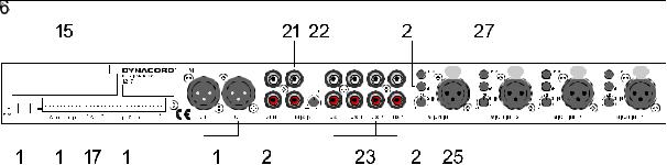
2.2 Rear Panel
14, 24 V power supply
These two 6.3mm flat-connectors are utilized to supply the DRM 4000 with an operating voltage of 24 V DC. Whenever incorporating the DRM 4000 in an intercom system, using the system’s already existing supply voltage of 24 V is recommended. For stand-alone operation use the optionally available mains adapter (NRS 90257). Make sure to mind the correct polarity (+ = +24V, - = Ground) when connecting the power supply.
15, REMOTE INTERFACE port
This port allows retrofitting an optional serial interface (RS-232 or RS-485). For further detail, please refer to chapter 9.3 “How To Install Extensions”.
16, CONTROL IN
These control inputs provide access to eight programmable internal states, including: signal routing, ducking control (priority function), level settings, mute, etc. Connecting it to ground activates a control input. The configuration is factory pre-set for using the DRM 4000 in a multitude of applications. Utilizing a serial interface (optionally available) allows configuring the functions of the eight control inputs via PC-software according to your personal needs. These setting can be saved in the DRM 4000. For details on the pin-assignment and an example of how connection is established, please refer to chapter 4.4.1.
17, External VCA-control
These control contacts allow the connection of two external potentiometers for remotely controlling the volume settings of Master A and B. The VCA’s of the two master outputs A or B are controlled by DC-voltage. Please, keep in mind that audio levels of eventually prioritized microphones (Priority Override is enabled) are not attenuated by VCA-control. For details on the pin-assignment and an example of how connection is established, please refer to chapter 4.4.2.
18, DIRECT OUT
Each of the eight input channels (MIC/LINE single-channel and AUX two-channel) has an individual direct output. It is possible to internally assign the direct outputs to PRE (the signal path is split prior to the tone control and volume setting section) or POST (the signal path is split after the tone control and volume setting section). For details on the pin-assignment, please refer to chapter 4.3.3.
19, Master Outputs OUT A / B
These are the two balanced XLR-type outputs of the DRM 4000. They can be used as L/R-stereo or as two separate monaural outputs, depending on the configuration of the DRM4000.
2-3

CONTROLS AND CONNECTIONS
20, SEND output
The pre-master A/B audio signal of the output channels is present at these two RCA-type connectors. Therefore, these outputs can be utilized for easy expanding / cascading several DRM 4000.
21, MIX IN input
This unbalanced stereo/dual input can be used connecting another mixer or an additional DRM 4000 allowing easy expanding / cascading.
22, MIX IN control
This control allows matching the level of the input signal to the MIX IN input. Setting the control to its center position (0 dB) leaves the audio signal unaltered. Turning it clockwise provides amplification of up to +10 dB while turning it counterclockwise attenuates the level accordingly.
23, AUX 1-4 RCA-type inputs
These RCA-type inputs allow connecting unbalanced Line-level signal sources, like for instance CDPlayers, Cassette Decks, Tuners, etc., to the AUX 1-4 channels.
24, Gain control
These controls allow separately setting the input levels of each MIC/LINE input channel in an amplification range between +10 dB and +60 dB. It is recommended to set the input level so that it matches the desired nominal level or to match the appliance’s optimum internal operation level using the gain controls. In this way you obtain the optimum S/N-ratio. In doing so make sure that the signal-LED lights constantly while, even at the loudest signal peaks, the peak-LED is just not lit.
25, MIC/LINE 1-4 XLR-type inputs
These XLR-type inputs allow connecting balanced signal sources to the MIC/LINE 1-4 channels. The inputs can be matched for use with an extremely wide level range. They are designed to accept microphone levels as well as Line-level signal sources.
26, PAD-switch
Engaging this switch attenuates the audio signals by -30 dB providing the possibility of connecting LINE and MIC signal sources to a single connector. When the switch is not engaged, the corresponding input is configured for the connection of microphones. Engaging the switch allows connecting a balanced LINE-level signal source to the corresponding XLR-type connector.
27, +24V-switch
These switches allow individually activating 24 V phantom power for each MIC/LINE-channel, which allows the connection of condenser microphones or phantom-powered paging consoles.
2-4

QUICK START
3. QUICK START
This paragraph describes in an overview the most important steps for a trouble-free operation of the DRM 4000 in your PA-system. For a more detailed description of specific functions when using the DRM 4000 in combination with the DPM 4000, please refer to chapter 6.4. For further details on the functioning and the configuration of the DRM 4000, please refer to the corresponding paragraph in the handbook.
POWER SUPPLY
Connect the DRM 4000 to a 24 V DC power source via the 6.3mm flat-connectors (14) on the rear panel.
AUDIO CONNECTIONS
Before integrating and initially operating the DRM 4000 in your PA-system, you should determine which system configuration you are using. Please refer to chapter 8 “CONFIGURING THE DRM 4000" for a wiring example for the BASIC CONFIGURATION 8-in-2 mixer as well as for notes on how to configure the DRM 4000. Please refer to the additional sheet ”DRM 4000 FACTORY CONFIGURATION" for an overview of the factory pre-set assignment of the BASIC CONFIGURATION and the CONTROL INPUTS. After doing so, connect the DRM 4000 according to the chosen configuration. Do not power-on any connected audio signal source yet.
POWER ON OPERATION
After including the DRM 4000 in your PA-system and before operating it for the first time, please set the input controls MIC/LINE 1-4 (4) and AUX 1-4 (7) all the way counterclockwise, so that actually no audio signal is fed to the audio outputs. Proceed in the same way with the gain controls (24) of the input channels MIC/LINE 1-4 on the rear panel of the appliance. Set them to +10 dB (counterclockwise margin). The DRM 4000 is factory pre-configured to be used as 8-in-2 mixer, which is a universal configuration in stereo mode. In case the appliance had previously been operated, it may start-up in any other configuration.
LEVEL SETTING
Set both master controls (10) to their counterclockwise margins, so that actually no audio signal is present at the audio outputs of the DRM 4000. Now, activate the previously connected sound source. If this audio signal source is connected to one of the MIC/LINE-inputs, carefully turn the corresponding gain control (24) on the rear panel of the appliance in clockwise direction. The green SIGNAL-LED (3) indicates signal presence. If the red PEAK-LED (3) lights, reducing the input amplification by turning the gain control counterclockwise will prevent possible distortion. Now, you can turn the input control MIC/LINE (4) or AUX
(7) as well as both MASTER-controls (10) clockwise. The audio signal is present at the XLR-type output connectors (19) on the rear panel of the DRM 4000 and the momentary level reading is indicated via the level-meter LED-chains (11).
3-1
INSTALLATION AND CONNECTIONS
4. INSTALLATION AND CONNECTIONS
4.1 General Notes
Achieving the best results possible with your DRM 4000 is only doable when making sure that all connections are in perfect order. For operating the appliance, connect its power supply via the flat-con- nectors on the rear panel to a 24 V DC power source. When incorporating the DRM 4000 in a PA or intercom system, using the already present 24 V supply voltage is recommended. For including the DRM 4000 in other applications, please use the optionally available mains adapter (NRS 90257). The adapter includes a universal input power supply with matching AMP-connectors, which directly fits the power supply connection (14) of the DRM 4000.
CAUTION: When establishing the power supply connection, make sure to connect the positive conductor (24 V) to the +24V-input of the DRM 4000 and the negative conductor (Ground) to the negative input.
To prevent any trouble with temperature, providing sufficient ventilation is as advisable as not to operate the DRM 4000 in environments with ambient temperatures exceeding 40°C. One Height-Unit is necessary for rack-installation. Normally, in this case, there are no special measures, like rack blinds, for ventilation necessary. Like with any other LF-signal processing unit, it is not recommended to install or operate the DRM 4000 directly above or below any device that generates a massive magnetic field; e.g. power amplifiers. In this way the risk of unwanted interference is reduced to a minimum. Before switching the DRM 4000’s power on, make sure that all necessary connections have been established. Start with connecting all microphones and other audio signal sources to the inputs of the DRM 4000. Then proceed with connecting the outputs of the DRM 4000 with the inputs of any consecutive device, e.g. power amplifier or DPM 4000. Make sure to also connect the direct-outs, if you are using them.
IMPORTANT: - Always use high-performance, properly shielded cables.
-When establishing connections (especially input connections) make sure that the connection cords do not exceed 10 m in length to prevent the loss of treble frequencies.
4.2Input Assignment
4.2.1 MIC/LINE inputs
The MIC/LINE-inputs (1 and 25) are provided via XLR-type sockets. The pin-assignment for the XLR-type plugs to be connected has to be: pin 1 = ground (shield), pin 2 = hot (+), pin 3 = cold (-). In case that the inputs are galvanic separated via transformers (NRS 90233), do not connect the shield to the ground of the sending device. The MIC/LINE 1-4 inputs can also be used with unbalanced signal sources. If so, please mind the following pin-assignment: pin 1 = ground (shield), pin 2 = hot (+). For avoiding a signal level attenuation by 6 dB, please interconnect the pins 1 and 3 inside the XLR-type plug. However, if this causes noise interference, remove the bridge again.
The following shows examples for balanced and unbalanced pin-assignments for audio cables, like they are commonly used with the DRM 4000.
4-1

INSTALLATION AND CONNECTIONS
4.2.2 AUX and MIX IN inputs
The four AUX-inputs (2 and 23) and the MIX IN-input (21) are provided via RCA-type jacks, which allows the direct connection of common unbalanced audio equipment (CD-Player, Tape Deck, Tuner, etc.). Usually, the needed connection cords are supplied together with the corresponding device. They are also available at basically any electronics store. Especially when using unbalanced cables, cable length matters: the shorter the cable, the smaller the risk of gaining additional noise interference.
4.3 Output Assignment
4.3.1 MASTER outputs
The two low-impedance MASTER outputs (19) are electronically balanced and provided via XLR-type connectors, which allows the use of longer cables. All summed MIC/LINE, AUX and MIX IN input signals are outputted via the MASTER outputs. When the DRM 4000 is used in stand-alone operation, the MASTER outputs are typically connected to the inputs of an external power amplifier. When incorporating the DRM 4000 in an intercom system, the MASTER outputs are connected to the inputs of the consecutive central unit (e.g. DPM 4000 or mixer / router).
4.3.2 SEND outputs
The Pre-Fader Master A/B signals are present at the SEND outputs (20) carrying the summed audio signals with the volume levels being independent from the setting of the MASTER controls. Therefore, when connecting the SEND OUT to the MIX IN of a following unit, allows comfortably cascading several DRM 4000 units, which of course doubles the amount of available input channels. For the case that additional input channels are needed cascading up to eight DRM 4000 units is possible. Using the SEND outputs for any other application that requires a summed signal input is possible as well. Examples for such applications are: the connection of open reel recorders, tape decks, or DAT / Minidisc devices for recording purposes as well as the incorporation of a monitor power amplifier or an active monitor speaker system. Since the SEND outputs are unbalanced, cable length matters. Using long cables is not recommended.
4.3.3 DIRECT OUTPUTS
The eight input channels provide DIRECT OUTPUTS (18) each. 12 unbalanced, low-impedance outputs are provided via the Phoenix-type terminal on the rear of the appliance (4 x MIC/LINE and 4 x 2 AUX), allowing separately outputting the input signals for pre-listening / monitoring or other signal-routing purposes. Internal Jumper provide the possibility to individually select for each input channel whether its DIRECT OUT signal path is split PRE - before entering the tone control and volume setting stage - or POST. For details on the location of the wire-bridges that are used for PRE/POST-switching, please refer to chapter 9.1.2. For details on the pin-assignment of the DIRECT OUT connectors, please refer to the following diagram. Make sure to use shielded LF-cables.
4-2
 Loading...