


TM
Length: 16.5" [435mm] Width: 7.7" [195mm] Height: 4.6" [115mm] Weight: 3.1 lb [1.4kg] Wheelbase: 10.1" [255mm]
Technical Support Information
For technical assistance, contact: DuraTrax Product Support 3002 N. Apollo Drive, Suite 1 Champaign, IL 61822
(217) 398-8970, Ext. 5 carsupport@duratrax.com
ASSEMBLY AND OPERATION MANUAL
Warranty
•DuraTrax® will warranty this kit for 90 days after the purchase date from defects in materials or workmanship. DuraTrax will either repair or replace, at no charge, the incorrectly made part. Exception: Specific parts covered under the Stress Tech™ Guarantee, see page 3.
•Make sure you save the receipt or invoice you were given when you bought your model! It is your proof of purchase and we must see it before we can honor the warranty.
•To return your Street Force GP2 for repairs covered under warranty, you should send your truck to:
Hobby Services
3002 N. Apollo Drive Suite 1
Champaign, Illinois 61822
Attn: Service Department
Phone: (217) 398-0007 9:00 am-5:00 pm Central Time M-F E-mail: hobbyservices@hobbico.com
If the buyer is not prepared to accept the liability associated with the use of this product, the buyer is advised to return this kit immediately in new and unused condition to the place of purchase.
READ THROUGH THIS MANUAL BEFORE STARTING. IT CONTAINS IMPORTANT INSTRUCTIONS AND WARNINGS CONCERNING THE ASSEMBLY AND USE OF THIS MODEL.
Copyright © 2004 |
DTXZ1044 For DTXC0052/DTXD52** |

TABLE OF CONTENTS |
|
Introduction....................................................................... |
2 |
Safety Precautions ........................................................... |
2 |
Helpful Hints ..................................................................... |
2 |
Stress-Tech™ Parts Guarantee ........................................ |
2 |
Repair Service .................................................................. |
2 |
Specification & Description Changes ............................ |
3 |
Screw Information ............................................................ |
3 |
Required Items for Completion....................................... |
3 |
Tools You Will Need .......................................................... |
3 |
Finishing the RTR Version............................................... |
4 |
Air Filter Installation .................................................. |
4 |
Radio Set-Up .............................................................. |
4 |
Body Mounting........................................................... |
5 |
Assembly of the Pre-Built Version.................................. |
6 |
Preparing the Radio System..................................... |
6 |
Radio Set-Up .............................................................. |
6 |
Air Filter Installation .................................................. |
9 |
Body Mounting......................................................... |
10 |
Carburetor Settings........................................................ |
10 |
Breaking-In the Engine .................................................. |
11 |
Engine Maintenance....................................................... |
12 |
Performance Tuning ....................................................... |
13 |
Maintenance Tips............................................................ |
13 |
Assembly Guide ............................................................. |
14 |
Engine Trouble Shooting ............................................... |
19 |
INTRODUCTION
Thank you for purchasing the DuraTrax Street Force GP2. This manual contains the instructions you need to build, operate and maintain your new nitro R/C touring car. Read over this manual thoroughly before building or operating the Street Force GP2.
SAFETY PRECAUTIONS
When the safety precautions are followed, the Street Force GP2 will provide years of enjoyment. Use care and good sense at all times when operating this radio controlled touring car. Failure to use this vehicle in a safe, sensible manner can result in injury or damage to property. You and you alone must insure that the instructions are carefully followed and all safety precautions are obeyed.
•Do not operate the Street Force GP2 near people. Spectators should be behind the driver or at a safe distance away from the vehicle.
•The engine and exhaust produce quite a bit of noise. If you are disturbed by the amount of noise this touring car produces, wear ear protection such as earplugs. Do not run this vehicle when or where it can disturb others.
•The engine and exhaust can become very hot. Avoid touching any of these parts during use and until they have cooled down.
•Model engine fuel is poisonous. Make sure you read and follow all of the precautions on the fuel container. Keep fuel out of the reach of children.
•Model engine fuel is flammable and when ignited has a flame that is difficult to see. Avoid sparks, flames, smoking, or any other ignition source when fuel is near.
•The engine emits carbon dioxide just like real cars. Do not operate this model indoors.
•Before turning on the transmitter, make sure that no one else is on your frequency.
HELPFUL HINTS
•Avoid working over a deep pile carpet. If you drop a small part or screw, it will be difficult to find.
•Place a mat or towel over your work surface.This will prevent parts from rolling off and will protect the work surface.
•Avoid running the touring car in cold weather. The plastic and metal parts can become brittle at low temperatures. In addition, grease and oil become thick, causing premature wear and poor performance.
•Test fit all parts before attaching them permanently.
STRESS-TECH™ PARTS GUARANTEE
We have engineered the Street Force GP2 to take the high speed abuse that makes R/C cars fun. We are so confident of the quality and durability of the Stress-Tech™ plastic parts that we will replace any Stress-Tech plastic part you break during the first 12 months you own the touring car. Just send in the part to us and we will send you a Free replacement. Please see the Street Force GP2 parts list for the items covered under the Stress-Tech guarantee.
To receive your free replacement part please send the following to the Hobby Services address listed on the cover of this manual:
•The broken part must be included.
•The part number and description of the broken part.
•Dated copy of your invoice or purchase receipt.
•Your name, phone number and shipping address.
REPAIR SERVICE
Repair service is available anytime.
•After the 90 day warranty, you can still have your Street Force GP2 repaired for a small charge by the experts at DuraTrax’s authorized repair facility, Hobby Services, at the address listed on the front page of this manual.
2
To speed up the repair process, please follow the |
REQUIRED ITEMS FOR COMPLETION |
instructions listed below. |
1.Under most circumstances return the ENTIRE system: To operate the Street Force GP2 these items are required: touring car and radio. The exception would be sending in
|
a Stress-Tech part. See the instructions under Stress- |
• Fuel (DuraTrax Red Alert™ fuel - DTXP0520) |
||
|
Tech Guarantee. |
• Air Filter Oil (DTXC2465) |
||
|
|
• Glow plug wrench (DTXR1170) |
||
2. |
Make sure the transmitter is turned off, all batteries are |
• It is also helpful to have a couple of extra glow plugs |
||
|
removed and fuel is drained from the tank. |
|
on hand (DuraTrax Carbon Speed DTXG3003) |
|
3. |
Send written instructions which include: a list of all items |
|
|
|
|
|
|
||
|
returned, a THOROUGH explanation of the problem, the |
|
|
|
|
service needed and your phone number during the day. If |
|
|
|
|
you expect the repair to be covered under warranty, be |
|
|
|
|
sure to include a proof of date of purchase (your store |
|
|
|
|
receipt or purchase invoice). |
|
|
|
4. |
Also be sure to include your full return address. |
|
|
|

 SPECIFICATION & DESCRIPTION CHANGES

All pictures, descriptions and specifications found in this instruction manual are subject to change without notice. DuraTrax maintains no responsibility for inadvertent errors in this manual.
|
|
|
|
|
|
|
|
|
|
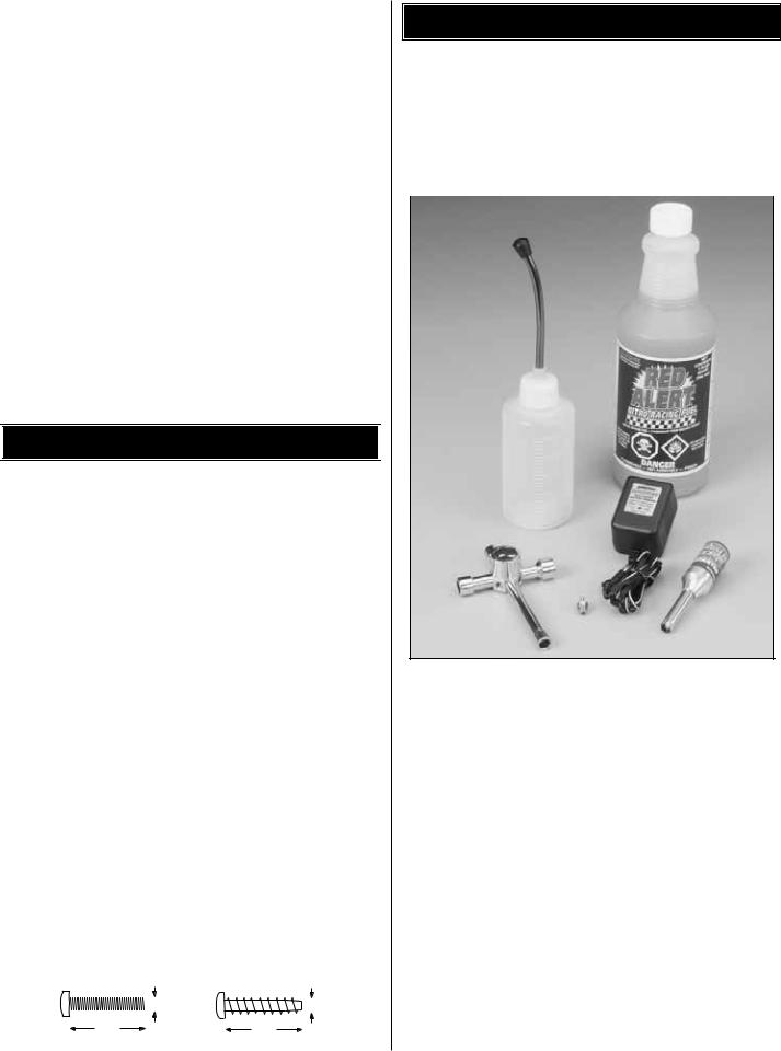
The Nitro Starter Pack from DuraTrax (DTXP0200) |
|||
|
|
|
SCREW INFORMATION |
|
|||||||||
|
|
|
|
includes fuel, deluxe wrench, fuel bottle, rechargeable |
|||||||||
|
|
|
|
|
|
|
|
|
|
glowplug starter and a glow plug. |
|||
|
|
|
|
|
|
|
|
|
|
||||
Do not use too much force when tightening self-tapping |
|||||||||||||
|
|
|
|||||||||||
screws into plastic. Overtightening will cause the threads in |
For the Pre-Built version of the Street Force GP2, you will |
||||||||||||
the plastic to strip. We recommend that you stop turning a |
also need: |
||||||||||||
self-tapping screw when you feel some resistance as the |
|
|
|
||||||||||
head of the screw comes in contact with the plastic. Avoid |
• 2-Channel radio with two standard servos (FUTJ14**). |
||||||||||||
using powered screwdrivers when assembling this kit. They |
• (12) “AA” batteries - four for the receiver and eight for |
||||||||||||
tend to overtighten the screws. Do not use thread locking |
|
the transmitter. |
|||||||||||
compound on any self-tapping screws. The thread locking |
• Small bottle of thread locking compound (DTXR2010). |
||||||||||||
compound may damage the plastic. IMPORTANT: Use |
|
|
|
||||||||||
thread lock on any fastener that is threaded into metal or |
|
|
|
||||||||||
fastened with a nut. Vibration from the engine will cause the |
|
|
|
||||||||||
|
TOOLS YOU WILL NEED |
|
|||||||||||
screws to loosen if thread locking compound is not used. |
|
|
|||||||||||
|
|
|
|
|
|
|
|
|
|
|
|
|
|
|
|
|
|
|
|
M3x14 |
To assemble the Pre-Built version (DTXC0052), you will |
||||||
|
|
|
|
|
|
need the following tools: |
|||||||
|
|
|
M3x14 Screw |
Self-Tapping |
|||||||||
|
|
|
Screw |
|
|
|
|||||||
|
|
|
|
|
|
|
|
|
|||||
|
|
|
|
|
|
|
|
|
|
• Phillips head screwdriver (DTXR0122) |
|||
|
|
|
|
3mm |
|
3mm |
|||||||
|
|
|
14mm |
|
|
14mm |
|
|
|
• Needle-nose pliers (DTXR0300) |
|||
|
|
|
|
|
|
|
|
||||||
|
|
|
|
|
|
|
|
||||||
|
|
|
|
|
|
• Hobby knife (HCAR0105), #11 blades (HCAR0211) |
|||||||
|
|
|
|
|
|
|
|
|
|
||||
3

FINISHING THE STREET FORCE GP2 TOURING CAR RTR VERSION (DTXD52**)
AIR FILTER INSTALLATION
1. Install the air filter onto the carburetor. Using the included tie-strap, secure the air filter to the carburetor. Cut off any excess portion of the tie-strap to avoid interference.
RADIO SET-UP
2. Remove the twist-tie from around the receiver antenna wire. Run the length of the antenna wire through your fingers to help straighten the wire out. This will make it easier to get the wire through the antenna tube. Slide the antenna wire through the antenna tube. Press the antenna tube into the antenna mount molded into the top of the radio plate.
3. Frequently, there will be leftover wire protruding from the antenna tube. Do not cut or coil the antenna! Cut two pieces of fuel tubing 1/8" long and slide them over the outside of the antenna tube and wire. This is to help hold the excess antenna onto the tube and avoid getting the antenna wire cut in a roll over. Note the placement of the fuel tubing on the antenna tube.
4. It may be necessary to loosen the radio plate to remove the receiver battery holder. Install 4 "AA" batteries (included) into the receiver battery holder in the configuration molded into the battery holder. Install the receiver battery back into the receiver battery holder as shown. Make sure to re-tighten the radio plate screws once the receiver battery is in place.
4
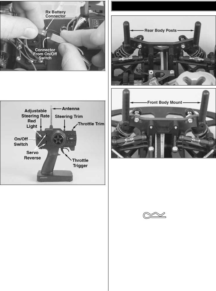
5. Plug the male end of the wire from the receiver (RX) battery into the female end from the on/off switch.
6. Install the transmitter antenna by screwing it into the hole on the top of the transmitter. Give the antenna a mild tug to make sure that it is properly secured in the transmitter.
7. Slide open the battery door on the bottom of the transmitter. Install eight (8) “AA” batteries into the transmitter in the configuration molded into the plastic on the battery holder. Reinstall the battery door.
8. Warning: Always extend the transmitter antenna before operating your vehicle. Turn on the transmitter using the switch on the side. The red light on the side of the transmitter should light up. If there is no light on, turn the transmitter off and check to ensure that the batteries are making contact with the metal contacts in the battery holder. Make sure the batteries are installed correctly. Turn the transmitter on and check for the red light. If the red light appears, turn off the transmitter. If the red light blinks, the batteries are low and should be replaced.
BODY MOUNTING
9. Raise the body posts to the upright position. Notice there is a molded pin that fits into a hole in the shock tower. This is to keep the body posts from swiveling during running. Tighten the screws in the body posts, making sure that the posts pull tight against the shock towers. You will have to remove the screws in the tops of the front shocks to get to the front body mount screws.
10. Apply the decals to the body.
BODY CLIP
11. Remove the body clips from the parts bag. On the front body posts place a body clip in the bottom hole of each post. On the rear body posts place a body clip in the third hole from the bottom in each post. Place the body onto the body mounts. On each body post place a body clip to secure the body onto the chassis. The excess body post can be trimmed off if desired.
You are ready to go! Watch the DVD for information on breaking in the engine and turn to page 10 for performance and maintenance tips.
5
ASSEMBLY OF THE STREET FORCE GP2 TOURING CAR PRE-BUILT VERSION (DTXC0052)
PREPARING THE RADIO SYSTEM
1. Install the “AA” batteries in the transmitter and the receiver holders.
2. Extend the transmitter antenna.
3. Connect the steering servo, throttle servo and receiver battery to the receiver.
4. Extend the receiver antenna.
5. Adjust the servo trims of the transmitter to the neutral position.
6. Switch on the transmitter.
7. Switch on the receiver.
8. Operate the steering and throttle control. Make sure the servo arms move in proportion to the movement of the steering wheel and throttle trigger.
9. Switch off the receiver, then the transmitter.
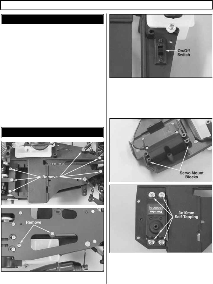
RADIO SET-UP
1. Remove the radio plate from the chassis by removing the 9 screws as indicated in the above photos.
2. Install the on/off switch into the slot in front of the fuel tank. Remove the face plate from the switch, then install the switch up through the bottom of the radio plate, and then install the face plate onto the top of the radio plate. Re-install the two screws through the face plate and into the switch to secure it to the radio plate. Be careful to put the switch plate on correctly with respect to on and off switch positions.
3. Install the throttle/brake servo into the slot next to the fuel tank. Place the two servo mount blocks onto the bottom of the radio plate. Then install the four 3x10mm self-tapping screws through the servo into the servo mounts. Route the servo wire through the slotted hole between the servo and the receiver battery holder.
6
 Loading...