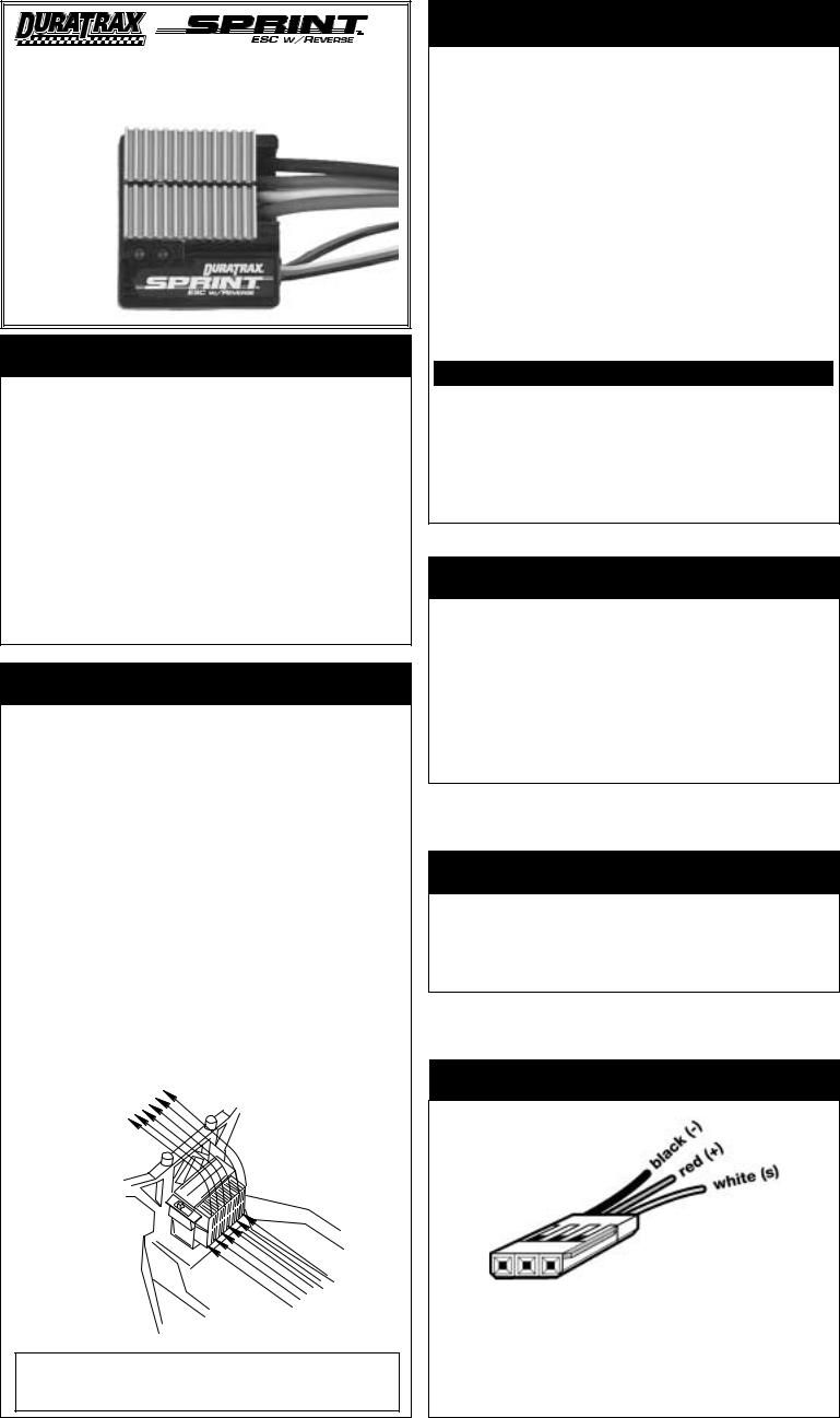
Duratrax Sprint ESC User Manual

Automatic Forward/Reverse MOSFET |
ELECTRONIC SPEED CONTROL |
OPERATING INSTRUCTIONS |
IMPORTANT INSTRUCTIONS
(ESC=ELECTRONIC SPEED CONTROL)
•Do not run the car near water! Never allow water, moisture, or any foreign material onto the ESC's PC board.
•Never use more than 7 cells (8.4 volts total) in the main battery pack.
•Do not mix instructions. If you are building a vehicle that has a mechanical speed control, do not use the wiring diagram included with the vehicle.
•Never cut or splice the ESC input harness wires. The receiver does not need to have anything plugged into the "battery" slot. It receives power through the ESC input harness which plugs into the CHANNEL 2 slot.
•Two 0.1µF (50V) monolithic capacitors (not included) should be properly installed on any motor that does not have capacitors built in. (See step 2)
•Always disconnect the battery pack from the ESC when not in use.
•Never turn on the ESC before plugging it into the receiver and switching on the transmitter.
•Be careful not to touch the heat sink when it is hot.
PLEASE FOLLOW ALL INSTRUCTIONS CAREFULLY!
STEP 1
MOUNTING THE SPEED CONTROL
The following mounting information will assure that your speed control performs at maximum efficiency and minimizes the chances of overheating and radio interference problems.
Mounting the Speed Control (Figure 1)
1.Mount the ESC to the chassis using mounting tape. Mounting the ESC to achieve good airflow through the heat sinks is very important for maximum performance. The ESC should be mounted as far away from the receiver as possible to prevent radio interference.
2.Mount the ON/OFF switch in a convenient place using mounting tape or screws.
Mounting the Receiver
1.To prevent radio interference, mount the receiver and antenna at least two inches away from the motor, batteries, power wires, servo, or any large piece of metal - such as a metal chassis.
2.Mounting the receiver in the tub of the chassis greatly reduces the range of your radio and increases the chance of radio interference.
3.If your car has a graphite chassis, and you want to mount the receiver on the chassis, mounting the receiver on edge with the crystal and antenna as far away from the chassis as possible reduces the chance of radio interference.
Figure 1
|
Flo |
w |
Air |
|
|
|
|
Mount the speed control to obtain maximum parallel airflow THROUGH the heat sink. For off-road cars, or cars with a metal or graphite chassis, mount the ESC on the chassis, and the receiver and antenna on the rear shock tower to reduce radio interference.
INTRODUCTION TO
SPRINT INSTRUCTIONS
The following instructions will help you get trouble-free speed control operation. These simple steps will allow your speed control to achieve maximum performance and minimize the chance of problems due to incorrect installation.
Consult the specifications printed in the table below for limitations on the number of cells that the speed control can be used with. You should always ask your hobby dealer or call our service department before using the speed control for an application other than what is listed in these instructions.
The Sprint has a reverse polarity protection circuit, which protects the speed control if the battery pack is hooked-up backwards. To reset the ESC turn it off and then back on, there is not a delay.
The Sprint is designed to be used with any 20-27 turn stock motor and run on 6 to 7 cells only (1.2 volts/cell connected in series). Using more than 7 cells may damage the speed control and void the warranty.
Specifications
|
Forward |
Reverse |
|
|
|
On-Resistance |
0.007 ohms |
0.014 ohms |
|
|
|
Max. Constant Current |
128 amps |
64 amps |
|
|
|
Battery Size |
7.2 to 8.4V (6-7 cells) |
|
|
|
|
Case Size (with heat sink) |
42mm x 38mm x 16mm |
|
|
|
|
Weight (with heat sink) |
|
60 g |
|
|
|
BEC Voltage / Amps |
5.0 volts / 1.0 amps |
|
|
|
|
STEP 2
HOOK-UP INSTRUCTIONS
Motors generate radio noise, which can interfere with your receiver and cause problems. Check your motor to see if it has capacitors installed on it. Some motors have capacitors built in so refer to the motor's instructions. If the motor does not have capacitors installed, you might need to install two (not included) 0.1µF, 50V, non-polarized, ceramic capacitors onto the motor. These capacitors will help reduce radio noise generated by the motor and prevent possible damage to the speed control. Solder the capacitors between:
•POSITIVE (+) motor brush tab & GROUND motor tab†.
•NEGATIVE (-) motor brush tab & GROUND motor tab†.
STEP 3
TRANSMITTER ADJUSTMENTS
Adjusting your transmitter is critical for proper speed control operation. The transmitter (TX) throttle adjustments are described below:
•ATV, EPA, or ATL - set all to maximum.
•Throttle Trims and Sub Trims - set all at neutral or zero.
STEP 4
RADIO CONNECTOR POLARITIES
 Clip tab
By simply clipping off the tab on the side of the connector using wire cutters, it can be directly connected to any Futaba® J, Airtronics "Z", Hitec "S", or JR receiver. For proper connection refer to your radio's manual. WARNING: This connector is NOT directly compatible with the old Airtronics connector style. For old Airtronics radios, it is highly recommended to use an Airtronics Servo Adapter to connect this ESC to the older style Airtronics radios. NEVER ALLOW THE RED (+) AND
BLACK (-) WIRES TO CROSS ON ANY RECEIVER OR ESC AS PERMANENT DAMAGE WILL RESULT TO BOTH ITEMS.
 Loading...