

Duke AHPO Installation Manual
OWNER’S MANUAL
AHPO/EPO
PROOFER OVEN
IMPORTANT INFORMATION
READ BEFORE USE
PLEASE SAVE THESE INSTRUCTIONS
Duke Manufacturing Co.
2305 N. Broadway • St. Louis, MO 63102
800.735.3853 • 3.231.1130 • 314.231.5074 Fax
www.dukemfg.com
502821F
CONTENTS
Manufacturing Introduction 2
Safety Instruction 3
Spec Sheets 4
Main Features 5
Installation Instructions 6-9
Oven Start-Up 10
Proofer Operating Instructions 10-11
Oven Operating Instructions 12- 13
Care and Cleaning 14
Troubleshooting 15-16
Door Adjustments and Gasket Maintenance 17 -2 2
Air-wash door Information and Cleaning Instructions 23
Bulb Mounting Details 24
Parts List and Illustrations 25 -27
Wiring Diagrams 28
Customer Assistance 29
Manufacturers Introduction
The Duke AHPO or EPO Proofer Oven were developed
in response to Customer’s need for uniform baking
capabilities to provide consistently high, “just baked”
bread quality .
The Duke Proofer Oven utilizes Duke’s unique directional
convection airflow technology that provides even heat
distribution and a uniform bake without the need for
turning pans during the bake cycle. This enhances the
quality and consistency of the baked products while
reducing food scrap/waste and simplifying operating
procedures.
The low profile oven won’t block the view of menu boards
and will easily roll through a standard height door . The
oven and proofer doors are field reversible with a drip
channel on the proofer door to prevent water from
dripping on the floor.
Full width doors on the oven and proofer help to display
and merchandise fresh baked bread to the customer.
The controls are simple to operate, there are two timers
for independent timing of the proofer and oven.
The full width oven and proofer cavity will accept
standard ½ size or full size sheet pans.
Supplier Name: Duke Manufacturing Co.
Address: 2305 N. Broadway
St. Louis, MO 63102
Model #:
AHPO-6/18-208
AHPO-6/18-230
Note:“230V” can be used
for 220-240V
1Ph or 3Ph
AHPO-6/18-400
EPO-3/9-208
EPO-3/9-230
3N (3Ph w/neutral)
Note:“230V” can be used
for 220-240V
1Ph or 3Ph
EPO-3/9-400
3N (3 Ph w/neutral)
Serial #:
Date
Received:
Date
Installed:
T elephone: (800) 735-DUKE (3853)
(314) 231-1 130
Fax: (314) 231-5074
Service
Referral #:
Local
Service
Name:
Local
Service #:
Duke Manufacturing Co.
2305 N. Broadway • St. Louis, MO 63102
800.735.3853 • 3.231.1130 • 314.231.5074 Fax
www.dukemfg.com
2 of 29
IMPORTANT SAFETY INSTRUCTIONS
Throughout this manual, you will find the following safety words and symbols that signify important safety issues
with regards to operating or maintaining the equipment.
W ARNING
GENERAL WARNING. Indicates information important to the proper operation of
the equipment. Failure to observe may
result in damage to the equipment and/
or severe bodily injury or death.
CAUTION
GENERAL CAUTION. Indicates information important to the proper operation of
the equipment. Failure to observe may
result in damage to the equipment.
In addition to the warnings and cautions in this manual,
use the following guidelines for safe operation of the unit.
• Read all instructions before using equipment.
• For your safety, the equipment must be furnished
with a properly grounded cord connector. Do not
attempt to defeat the grounded connector.
• Install or locate the equipment only for its intended
use as described in this manual.
• Do not use corrosive chemicals in this equipment.
• Do not operate this equipment if it has a damaged
cord or plug, if it is not working properly, or if it has
been damaged or dropped.
• This equipment should be serviced by qualified personnel only. Contact the nearest Duke authorized
service facility for adjustment or repair .
• Do not block any openings on the unit.
• A minimum clearance of 6” (152,4 mm) from the top
of the unit to the ceiling must be provided.
• This appliance must be secured to building structure
(Restraining Device Kit).
• Keep cord away from heated surfaces.
• To prevent tipping, securely attach unit to the wall
using brackets provided.
W ARNING
ELECTRICAL WARNING. Indicates information relating to possible shock hazard.
Failure to observe may result in damage
to the equipment and/or severe bodily
injury or death.
W ARNING
HOT SURFACE WARNING. Indicates information important to the handling of
equipment and parts. Failure to observe
caution could result in personal injury.
The following warnings and cautions appear throughout
this manual and should be carefully observed.
• Turn the unit off, disconnect the power source and
allow unit to cool down before performing any service
or maintenance on the unit.
• The procedures in this manual may include the use
of chemical products. You must read the Material
Safety Data Sheets before using any of these products.
• The unit should be grounded according to local electrical codes to prevent the possibility of electrical
shock. It requires a grounded receptacle with separate electrical lines, protected by fuses or circuit
breaker of the proper rating.
• All electrical connections must be in accordance with
local electrical codes and / or any other applicable
codes.
• Disposal of the unit must be in accordance with local environmental codes and/or any other applicable
codes.
SAVE THESE INSTRUCTIONS
Duke Manufacturing Co.
2305 N. Broadway • St. Louis, MO 63102
800.735.3853 • 3.231.1130 • 314.231.5074 Fax
www.dukemfg.com
3 of 29
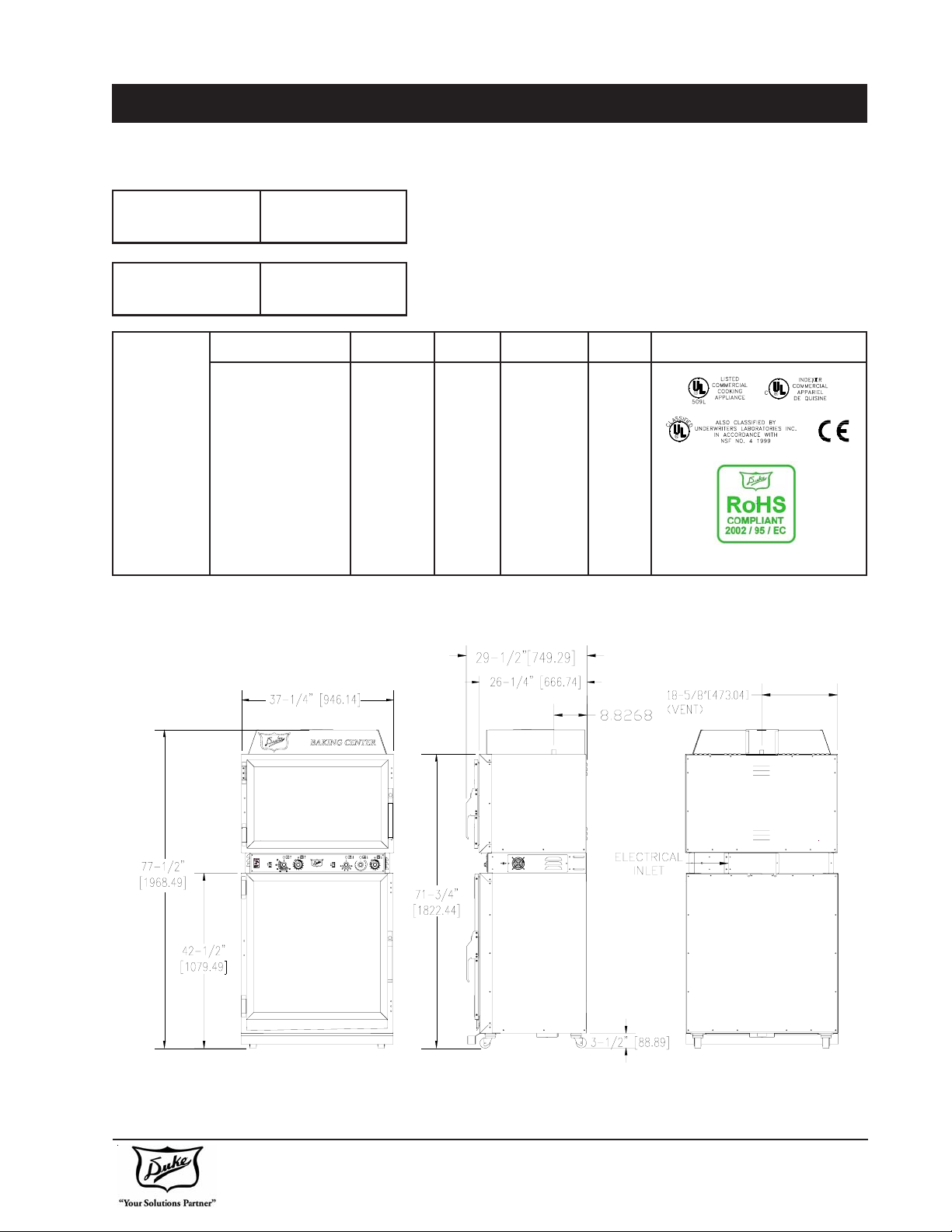
SPEC SHEET
U.S. Patent. Other US and Foreign Patents Pending
Model AHPO or EPO
Shipping Weight:
Carton Box
Shipping Weight:
Wooden Crate
208 1 60 6650 32.0
208 1 50 6650 32.0
230 (220-240) 1 6 0 6650 32.0
AHPO /
EPO
230 (220-240) 1 5 0 6650 32.0
230 (220-240) 3 6 0 6650 16.7
230 (220-240) 3 5 0 6650 16.7
400 (380-415) 3N 60 6650 16.7
400 (380-415) 3N 50 6650 16.7
625lbs/284 Kg
760lbs/345 Kg
Volts Phase Hz Watts Amps
Duke Manufacturing Co.
2305 N. Broadway • St. Louis, MO 63102
800.735.3853 • 3.231.1130 • 314.231.5074 Fax
www.dukemfg.com
4 of 29
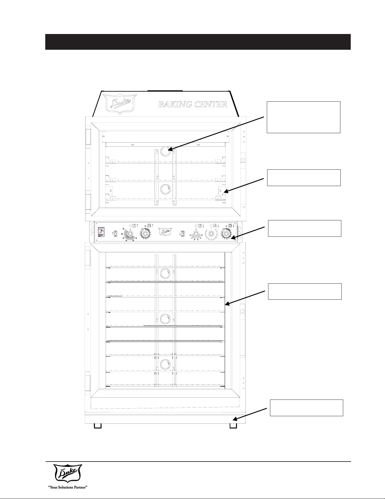
MAIN FEATURES
LOW VOL T AGE
LIGHTING SYSTEM
12V HALOGEN LAMP
CONVECTION OVEN
CONTROL P ANEL
PROOFER
DRIP P AN
800.735.3853 • 3.231.1130 • 314.231.5074 Fax
Duke Manufacturing Co.
2305 N. Broadway • St. Louis, MO 63102
www.dukemfg.com
5 of 29
INSTALLATION
Unpacking Unit
• Inspect the shipping carton and/or container, carefully noting any exterior damage on the delivery receipt, which was not evident on the outside of the
shipping container (concealed damage). Contact the
carrier immediately and file a damage claim with them.
Save all packing materials when filing a claim. Freight
damage claims are the responsibility of the purchaser
and are not covered by the warranty .
• Follow the instructions on the Carton Box for unpacking the unit.
• Inspect unit for damage such as, broken glass, etc.
• Report any dents or breakage to source of purchase
immediately .
• Do not attempt to use unit if damaged.
• Remove all materials from unit interior.
• If unit has been stored in extremely cold area, wait a
few hours before connecting power.
Unit Placement
• Do not install unit next to source of heat, such as
deep fat fryer, etc.
• Install unit on level surface floor.
• A Minimum Clearance of:
Unit Clearance
Right Side 0 ”
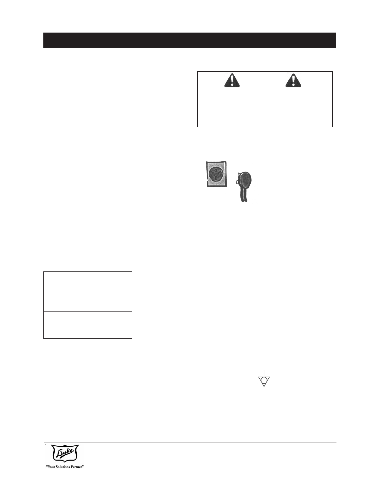
W ARNING
T o avoid risk of electrical shock or death,
this unit must be grounded or field connection must not be altered.
Earthing Instructions
Unit MUST be grounded.
Grounding reduces risk of
electric shock by providing an
escape wire for the electric
current if an electrical short
occurs. When using an ap-
propriate plug it must be
plugged into an outlet that is properly installed and
grounded.
Consult a qualified electrician or servicer if grounding
instructions are not completely understood, or if doubt
exists as to whether the oven is properly grounded.
Do not use an extension cord. This unit should be
plugged or field connected into a separate circuit with
the electrical rating as provided in product specifications.
All electrical connections must be in accordance with
local electrical codes and/or any other applicable codes.
Left Side 0”
External Equipotential
Rear 0”
Ceiling 6”
Must be maintained between the unit and any
combustible or non-combustible substance.
Proper airflow around unit cools electrical components.
With restricted airflow, unit may not operate properly
and life of electrical parts is reduced.
Duke Manufacturing Co.
2305 N. Broadway • St. Louis, MO 63102
800.735.3853 • 3.231.1130 • 314.231.5074 Fax
www.dukemfg.com
Earthing Terminal
Equipment has secondary earthing terminal.
Terminal provides external earthing connection
used in addition to earthing prong on plug. Located
on outside of oven back, terminal is marked with
this symbol.
6 of 29
INSTALLATION
1. Compare the voltage and phase from the oven specification label to the power supply for the oven and call Duke
if there is a difference. If the phase is wrong, a qualified service technician can change the wire connections
inside the oven to correct the problem. See the illustration on page 4 for phase conversions. If the voltage is
wrong, the heat elements must be changed. Call Duke to get new elements.
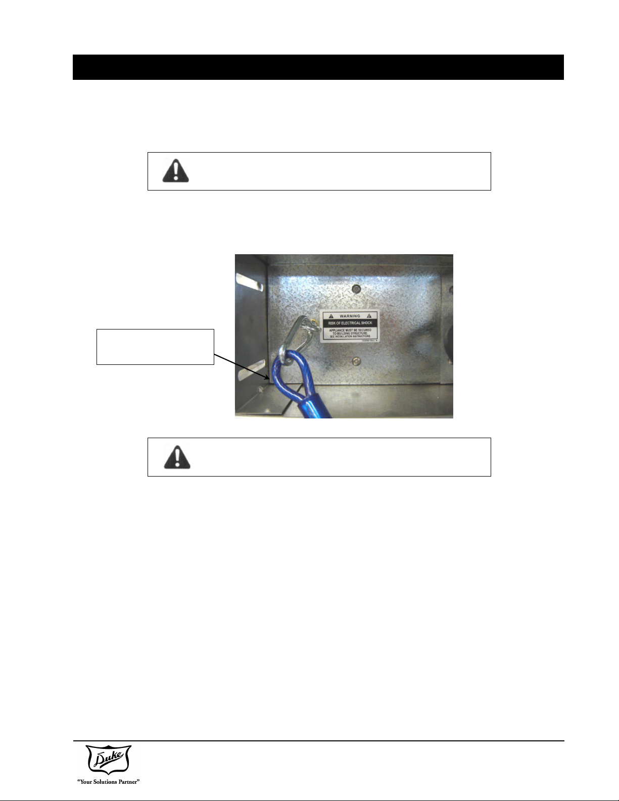
WARNING Risk of Injury
2. This appliance must be secured to building structure. A restraining device kit (#153586) was provided with the
unit to limit the movement of the appliance without depending on or transmitting stress to the electrical conduit.
Installation instruction is in the kit. Permanent installation of the unit requires that the utility connection be of
sufficient length to allow the equipment to be moved for cleaning.
RESTRAINING DEVICE
KIT (PART # 153586)
WARNING Risk of Electric Shock
This Restraining Device MUST always be connected when the Appliance is in Service. Disconnect for movement,
servicing and or cleaning, then reconnect when the appliance has been returned to its normal position.
The appliance shall be installed using flexible conduit or equivalent to meet the local electrical codes and shall be
of sufficient length to allow the equipment to be moved for cleaning.
3. IMPORTANT: A minimum clearance of 6” from the top of unit to the ceiling must be provided.
4. TO PREVENT FROM TIPPING: Unit must be permanently attached to wall using wall-mounting brackets. Refer
page 9 for the instructions on Installation of Wall Brackets to the wall.
5. Check the swing of the door. The hinge side can be changed by following the instructions on the following pages.
The door swing direction can be changed in the field after you have a new drip channel for the proofer door. Call
Duke to get the new drip channel for the proofer door.
6. Check the door seal and make sure both doors close completely. If they do not close and seal properly, call
Duke for assistance.
7. Place the wire racks in the oven and proofer.
Duke Manufacturing Co.
2305 N. Broadway • St. Louis, MO 63102
800.735.3853 • 3.231.1130 • 314.231.5074 Fax
www.dukemfg.com
7 of 29
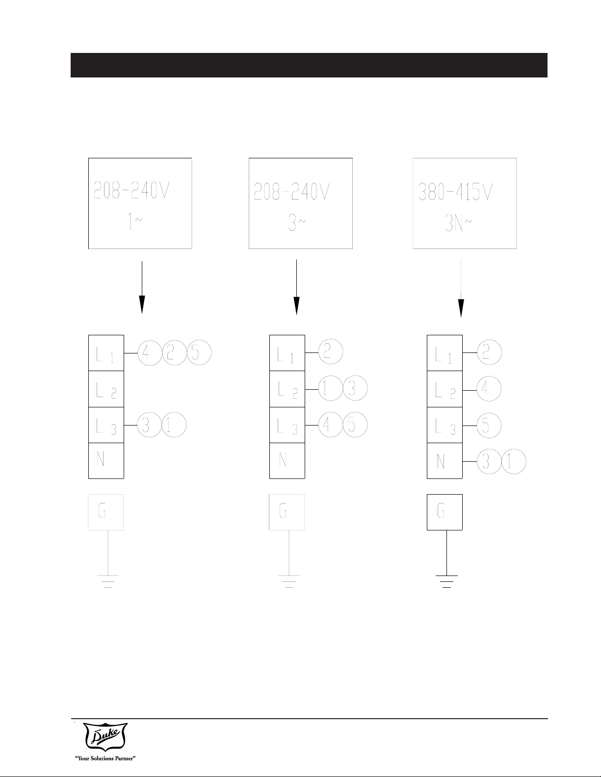
INSTALLATION
Illustration of the Wiring connection for single phase and three phase connections.
Duke Manufacturing Co.
2305 N. Broadway • St. Louis, MO 63102
800.735.3853 • 3.231.1130 • 314.231.5074 Fax
www.dukemfg.com
8 of 29

INSTALLATION
Instruction for the installation of W all Brackets to the wall for tipping!
1. Mount the Wall Mounting Bracket with screws provided to the Proofer Oven & extend the Wall Mounting Bracket
towards the wall by sliding it thru the slot provided. Do not tighten the screws.
2. Mark on the Wall & Drill in the Wall for fixing anchors for screws.
3. Insert the wall anchors into the already drilled holes on the wall.
4. Butt the Wall Mounting Bracket against the wall.
5. Insert the screws provided into the Wall Mounting Bracket to firmly secure it against the wall.
6. Please re-ensure that the Bracket is firmly secured to the wall. Tighten the screws into the unit.
HOLE DRILLED IN
WALL
WALL FOR FIXING
BRKT
WALL
WALL MOUNTING BRACKET
2305 N. Broadway • St. Louis, MO 63102
800.735.3853 • 3.231.1130 • 314.231.5074 Fax
www.dukemfg.com
Duke Manufacturing Co.
9 of 29
 Loading...