

Page 1
Jaundice Meter
Incorrect use of the instrument may result in accidents, so follow the
instruction manual to ensure correct and safe operation.
JM-103
Instruction Manual
Page 2
Safety Symbols
The following symbols are used in this manual and on the instrument to prevent accidents that may occur as a result of incorrect
use of the instrument.
Denotes a sentence regarding a safety warning or note.
Read the sentence carefully to ensure safe and correct use.
Denotes a prohibited operation.
The operation must never be performed.
Denotes an instruction.
The instruction must be strictly adhered to.
Denotes a prohibited operation.
Never disassemble the instrument.
Denotes an instruction.
Disconnect the AC power cord from the AC outlet.
This symbol indicates type BF Applied Part. The instrument
provides a particular degree of protection against electric
shock, particularly the leakage current and reliability of the
protective earth connection with an F-TYPE APPLIED PART.
F-TYPE APPLIED PART indicates applied part isolated from
all other parts of the instrument to such a degree that the patient leakage current allowable in single fault condition is not
exceeded when a voltage equal to 1.1 times the highest rated
mains voltage is applied between the applied part and earth.
This symbol indicates alternating current (AC).
This symbol indicates direct current (DC).
Page 3

Notes on this Manual
• Copying or reproduction of all or any part of the contents of this
manual without KONICA MINOLTA SENSING's permission is strictly
prohibited.
• The contents of this manual are subject to change without prior
notice.
• Every effort has been made in the preparation of this manual to ensure
the accuracy of its contents. However, should you have any questions
or find any errors, please contact a KONICA MINOLTA SENSING
authorized service facility.
• KONICA MINOLTA SENSING will not accept any responsibility for
consequences arising from the use of the instrument.
Authorized Standards
For North America
UL, cUL:
WITH RESPECT TO ELECTRICAL SHOCK,FIRE
AND MECHANICAL HAZARDS ONLYIN ACCORDANCE WITH UL 60601-1AND CAN/CSA
C22.2 No. 601.1
For Europe
CE (Medical Device Directive):
This instrument complies with EN60601-1,
EN60601-1-2, and EN ISO13485, and EN
ISO14971.
1
Page 4
SAFETY PRECAUTIONS
To ensure correct use of this instrument, read the following
points carefully and adhere to them. After reading this manual,
keep it in a safe place where it can be referred to anytime a
question arises.
WARNING
Do not use the instrument in areas where flammable or
combustible gases (anesthetic gas, gasoline fumes etc.) are
present. Doing so may result in a fire.
Always use the charger unit (JM-A30) and the AC adapter
(JM-A31, including the power cord) that are supplied with the
instrument, and connect the adapter to an AC outlet (100V,
50/60Hz). Using a charger unit and AC adapter other than
those mentioned above or connecting to a voltage other than
the one specified may result in damage to the instrument,
charger or AC adapter, fire or electric shock.
Do not insert or disconnect the AC power cord’s plug with
wet hands. Doing so may cause electric shock.
Do not disassemble or modify the instrument, Charger unit or
AC adapter. Doing so may cause a fire or electric shock.
2
Failure to adhere to the following points
may result in death or serious injury.
Page 5
Take special care not to allow liquid or metal objects to enter the instrument or charger unit. This may cause a fire or
electric shock. Should liquid or metal objects enter the instrument, turn the power OFF immediately, disconnect the AC
adapter from the AC outlet, and contact the nearest KONICA
MINOLTA SENSING authorized service facility.
The instrument, Charger unit and AC adapter should not be
operated if they are damaged, or if smoke or odd smells occur. Doing so may result in a fire. In such situations, turn
the power OFF immediately, disconnect the AC adapter from
the AC outlet, and contact the nearest KONICA MINOLTA
SENSING authorized service facility.
Failure to adhere to the following points
CAUTION
Never press the measuring probe when it is directed to the
eyes. Doing so may cause eye damage.
Do not place the instrument on an unstable or sloping surface. Doing so may result in the instrument or Charger unit
dropping or overturning, causing injury. When you carry the
instrument, take care not to let it drop.
Make sure that the instrument is placed near the AC outlet
and that the AC power cord’s plug can be easily connected
and disconnected.
may result in injury or damage to the instrument or other property.
3
Page 6

CONTENTS
SAFETY PRECAUTIONS …………………………………………… 2
Foreword ……………………………………………………………… 5
Contents of the package …………………………………………………… 7
Notes on Use ………………………………………………………………… 7
Notes on Storage …………………………………………………………… 9
Disposal Method …………………………………………………………… 9
Names of Parts …………………………………………………… 10
1) JM-103 main body ………………………………………………………10
2) Charger unit JM-A30 ……………………………………………………11
3) AC adapter JM-A31 ………………………………………………………11
Reading the Display …………………………………………………………12
Preparation ………………………………………………………… 13
1) Charging ……………………………………………………………………13
2) Inspecting …………………………………………………………………15
3) Attaching the Strap ………………………………………………………18
4) Selecting the Unit of Measurement ……………………………………19
Measurement ……………………………………………………… 21
Setting the Number of Average Measurements ………………………21
Measuring Procedure ………………………………………………………23
Removing from Charger ……………………………………………………23
Single Measurement ………………………………………………………24
Average Measurement (example using five times as the average) ……25
Storing the Instrument ………………………………………………………28
Trouble Shootings ………………………………………………… 29
Error Messages ………………………………………………………………29
Check Points before Repairing ……………………………………………31
Maintenance and Inspections ……………………………………………32
Cleaning ………………………………………………………………………32
Specifications ……………………………………………………… 33
Appendix …………………………………………………………… 35
EMC Guidance
EMC Guidance
Measuring Principle …………………………………………………………38
Clinical Test Result Report …………………………………………………40
4
(electromagnetic emissions) …………………………………… 35
(electromagnetic immunity) …………………………………… 36
Page 7
Foreword
Safety Notes
This instrument is designed for estimating total serum bilirubin
concentration, that is necessary for the screening of jaundice in
newborn infants. It must be used for newborn infants only.
Never press the measuring probe when it is directed to the eyes.
Doing so may cause eye damage.
To prevent kernicterus in newborn infants, it is very important to
detect jaundice in its early stages.
This hand-held jaundice meter allows a quick, non-invasive
estimate of total serum bilirubin concentration, necessary for the
control of jaundice in newborn infants.
Measurements are taken automatically by simply placing the
instrument’s measuring probe against the forehead or sternum
of the infant and pressing it gently, and the measured value is
displayed.
This facilitates use of the instrument for infants who are still kept
in incubators and provides suitable screening for jaundice. This
will also help detect jaundice in its early stages.
Foreword
This instrument considers the yellowness of the skin, which
consists of epidermis, dermis and subcutaneous tissue as the
optical density difference at two wavelengths, and it calculates
the difference only for the subcutaneous tissue by measuring
the difference between the two optical paths.
5
Page 8

Hemolytic jaundice
Foreword
Normally, in the case of hemolytic jaundice that appears before the
age of three days, measurement of total serum bilirubin concentration
must also be taken. (The correlation between the measured value
taken by the instrument and total serum bilirubin concentration drops
substantially due to physiologic factors.)
Precocious jaundice
If there is a possibility that the newborn infant is suffering from
precocious jaundice (incompatible blood type, hemolytic jaundice),
it is necessary to take frequent measurements or measure the total
serum bilirubin concentration as well. (There is a possibility that
bilirubin concentration in the subcutaneous tissue rises slower than
the total serum bilirubin concentration.)
When the newborn infant is undergoing photo-therapy
During photo-therapy, the bilirubin concentration in the subcutaneous
tissue under the area exposed to light decreases before the total
serum bilirubin concentration does, so it is necessary to limit the use
of this instrument only when photo-therapy equipment is used from
the back of the patient or affix a light-blocking patch to the measuring
point on the forehead or chest. (In areas exposed to light, there are
some cases in which only the bilirubin concentration in the subcutaneous tissue decreases before the total serum bilirubin concentration improves. In addition, if the total serum bilirubin concentration
increases again after therapy, there is a possibility that the bilirubin
concentration in the subcutaneous tissue will increase later.)
Measuring point
Measurements must be taken on the forehead or sternum, where a
sufficient amount of blood is circulated. (There is a chance that the
bilirubin concentration in the subcutaneous tissue is low for areas with
small amounts of blood and areas in which the subcutaneous tissue is
subject to keratinization.)
6
Page 9
Contents of the package
Before using the instrument, check to ensure that the following
items are included in the package.
1) Jaundice Merer JM-103 × 1
2) Charger Unit JM-A30 × 1
3) AC Adapter JM-A31 × 1
4) Strap × 1
5) Instruction Manual × 1
Notes on Use
● This instrument should be used under the following operating conditions.
• Temperature of 0 to 40°C (32 to 104°F), relative humidity of 30 to
85%, with no condensation.
• Atmospheric pressure of 700 to 1060 hPa (altitude of -400 to
3000m).
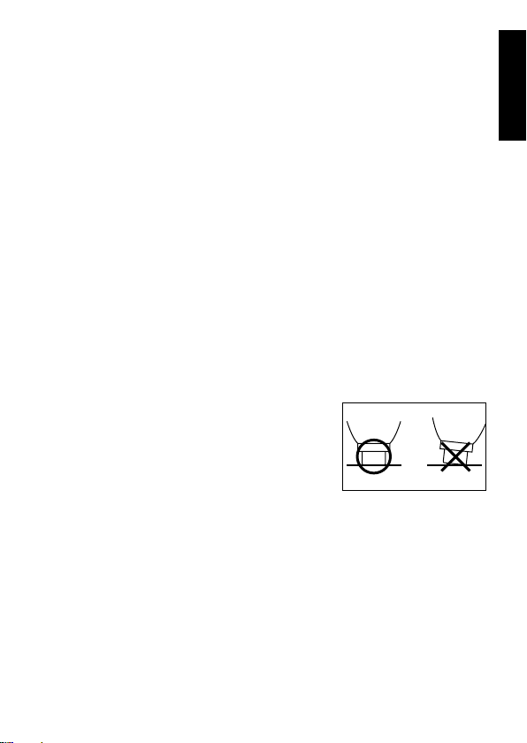
● When taking measurements, place the measuring probe perpendicular to the measuring point and then push it gently as shown
below. Placing the measuring probe at an
angle may result in fluctuation of measured
value.
● This instrument is a precision instrument, so it should not be dropped,
exposed to shocks and strong vibrations, nor should heavy objects
be placed on it. Failure to observe these cautions may cause breakdown.
● Do not use the instrument in areas where it may be exposed to rain or
water since it is not splash/water-proof. Also take special care not to
allow blood or other liquids to come in contact with the instrument.
Foreword
7
Page 10

● Do not use the instrument on a point where there is excessive vibra-
Foreword
tion. In addition, to avoid excessive impact on the instrument, it should
be handled gently. Failure to observe this may cause breakdown.
● Accurate measurement data may not be obtained in the following
cases.
• When ambient light (e.g. panel light, fluorescent light, infrared heat
lamp, direct sunlight) is too strong
• When influenced electromagnetically by other electronic devices
(e.g. near electrical appliances like TV, medial device)
• When a mobile telephone is used during measurement
● This instrument has a built-in battery. Do not disassemble the instrument to replace the battery.
● Use the Charger unit (JM-A30) and AC adapter (JM-A31) that are
supplied with the instrument.
● The Charger unit (JM-A30) and AC adapter (JM-A31) are solely designed for use with the JM-103, so they must never be used with any
other instrument.
● This instrument emits intense light to take measurements. Measurements should only be taken of the forehead or sternum, and the instrument should never be allowed to emit light directly into the eyes.
● If the instrument gets dirty, wipe it with a dry cloth or a cloth moistened
with mild, neutral detergent. (Never use a solvent such as thinner or
benzene to clean the instrument, since it may dissolve its casing.)
● The measuring probe should be cleaned by wiping with medicinal alcohol before use.
8
Page 11

Notes on Storage
● This instrument should be stored under the following storage conditions.
• Temperature of -10 to 60°C (14 to 140°F), relative humidity of 10 to
95%, with no condensation.
• Atmospheric pressure of 700 to 1060 hPa (altitude of -400 to
3000m).
● When storing the instrument:
• Do not store the instrument in an area where it will be ex-posed to
water.
• Do not store the instrument in an area where direct sunlight, pres-
sure, temperature, humidity, ventilation, sunlight, dust, strong magnetic fields, and/or saline or sulphurous atmospheres may affect
the instrument.
• Do not store the instrument on an inclined surface or on a surface
which may be subject to vibrations or physical shock. (Also avoid
vibrations or physical shock during transportation.)
• Do not store the instrument in areas where chemicals are stored or
where gas may be emitted.
• The instrument and its accessories should be cleaned thoroughly
and stored properly to make sure that there will be no problems
when they are used again. (For the cleaning method, refer to
“Cleaning” on page 32.)
Disposal Method
● The instrument has a built-in Ni-MH battery. Do not disassemble the
instrument or remove the battery. To dispose of or replace the battery,
contact the nearest KONICA MINOLTA SENSING authorized service
facility.
● When disposing of the instrument or its accessories, local laws and
regulations must be observed.
Foreword
9
Page 12
Foreword
Names of Parts
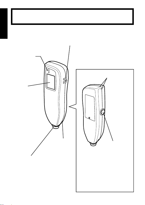
1) JM-103 main body
READY lamp
Lights up to indicate that the instrument is ready
for the next measurement.
Display
Displays the measured value etc.
❋For the method
of re ad in g th e
dis play, refer t o
“ Re ad ing th e
Display” on page
12
POWER switch
• Slide this switch to turn the power ON/
OFF.
• Using this switch in combin ation with
the RESET button allows you to switch
to check mode and change the unit of
measurement.
Strap attachment area
Attach the strap.
Measuring probe
Takes measurement
when pressed against
the measuring point.
10
Charger contact
Used to connect the
Charger unit.
• Deletes the currently d isplayed
RESET button
measured value and prepares for
the next measurement.
• Using this switch in combination
with the POWER switch allows
you to switch to check mode and
change the unit of measurement.
• In ad dition, holding this button
down allows you to set the number of average measurements to
be performed.
Page 13
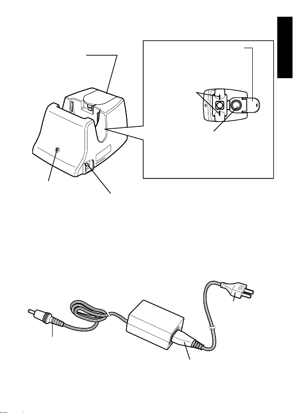
2) Charger unit JM-A30
Foreword
Checker cover
To check the instrument,
open this cover.
Charger jack
Used to connect
the main body.
Charger lamp
Lights up to indicate that
the instrument is currently charged.
DC jack
Used to connect the AC adapter.
3) AC adapter JM-A31
DC plug
Used to connect the charger’s DC jack.
Standard checker values
The reference values for check
mode are given.
Checker
Checks whether the instrument is operating correctly
by taking measurement in
check mode.
AC Power
cord’s plug
Connect into
an AC outlet.
AC Power cord
11
Page 14
Foreword
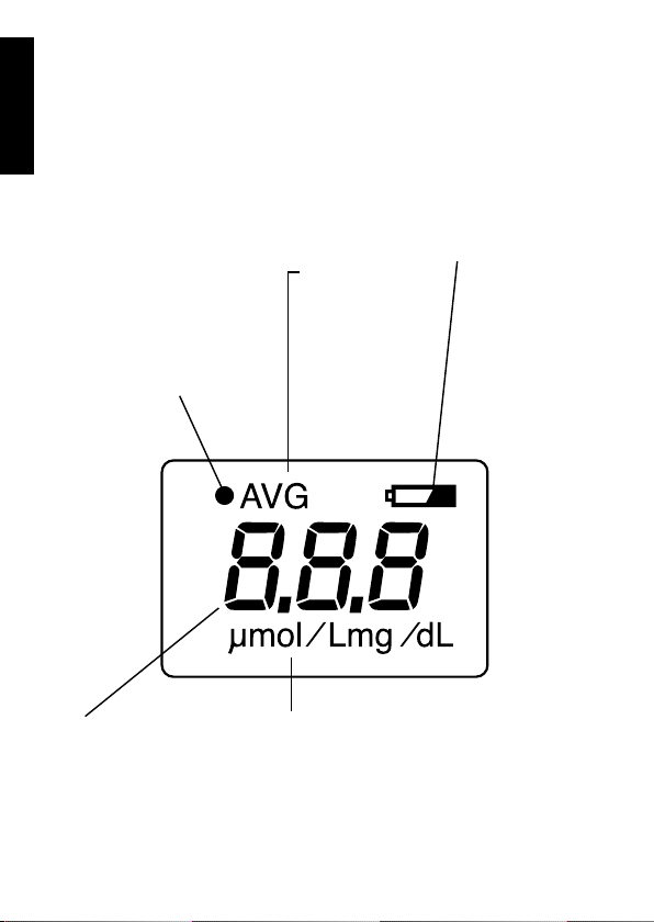
Reading the Display
The following items are displayed on the instrument display.
❋ In the following drawing, all the items are lit for explanatory purposes.
In actual operation, there are no cases where all of them are lit at the
same time.
Optical path
When performing inspections
with the checker, this will be
illuminated when the L value
is displayed (long optical path)
and extinguished when the S
value is displayed (short optical path).
Value
The measured values,
and other information
will be displayed.
12
AVG
Lights up during
averaging measurement.
Battery Indicate
(Battery mark)
Battery mark blinks
when the battery
power is low.
❋For details on bat-
Unit
Displays the unit of measurement. (mg/dL or μ mol/L)
tery d ispla y, refer
to “Battery Indica-
tion” on page 30.
Page 15

Preparation
Before starting measurements using this instrument, follow
the procedure given below to ensure that measurements are
stable.
1) Charging
● Ensure that the batteries have been charged when using it for the first
time.
● Ensure that JM-103 should be always placed in the charger unit to
charge the battery when not using the instrument for measurement.
● The battery display will blink when the battery power is low.
The power cord and AC
1
adapter are supplied separately. Before using the instrument, make sure that
the power cord is connected
to the AC adapter.
Connect the AC adapter’s
2
DC plug to the DC jack of
the Charger unit.
Preparation
DC jack
DC plug
13
Page 16

Connect the AC Power
3
cord’s plug into an AC outlet.
Preparation
Set the POWER switch on
4
the main body to OFF, and
then place the instrument
on the charger unit.
◆ Make sure that the display faces toward you. When the instrument is
set on the Charger unit properly, the
CHARGER lamp will light up.
◆ Charging will be completed in approximately 32 hours. Measurement
can be performed approximately 400
times with fully charged battery.
◆ Measurement can be performed approximately 100 times with 6 hours
battery charged.
◆ The power of the batteries will be diminished if the instrument is left uncharged for long periods of time, so
ensure that it is recharged prior to
use.
14
Page 17

2) Inspecting
● The instrument can be easily checked to ascertain that it is performing measurement correctly, by using the checker supplied with the
Charger unit.
● It is recommended that the instrument be checked once or more each
day it is used.
● Since the configuration of this instrument differs from that of old models, never use conventional checkers.
● Do not touch the checker’s surface with fingers. If the checker gets
dirty, wipe it with a soft cloth dampened with water, then wipe it with a
dry cloth.
Set the POWER switch to
1
ON while holding down the
RESET button.
Release the RESET button
2
immediately after “CHE”
is displayed on the display
window.
Preparation
◆ If the RESET button is held down for
more than 15 seconds, the unit of
measurement will be switched. If this
occurs, switch the unit back to the previous one. (For the method of switching the unit of measurement, refer to
“Selecting the Unit of Measurement”
on page 19.)
15
Page 18

Check to confirm that “CHE”
3
is displayed and that the
READY lamp is illuminated.
Preparation
Open the checker cover.
4
Place the measuring probe
5
perpendicular to the checker, and push it gently until a
click is heard.
◆ If the measuring probe is contacted
aslant with the checker, place it perpendicularly and take measurement
again.
Confirm the measured val-
6
ue.
◆ The display will interchange between
the L value (measured value of the
long optical path) and the S value
(measured value of the short optical
path). “●” appears in the upper left
corner of the display while the L value
is displayed.
Reference
values
L value (measured value of
the long optical path)
16
Page 19

◆ The values are acceptable if both the
L value and S value are within ±1.0 of
the reference values indicated on the
checker cover. (The L and S values
indicate the hardware characteristics.)
If the measured value exceeds ±1.0
of the reference value, clean both the
checker and probe, then take measurement again.
If ±1.0 of the reference value is still
exceeded, contact the nearest KONICA MINOLTA SENSING authorized
service facility.
Close the check cover.
7
Set the POWER switch to
8
OFF.
Preparation
S value (measured value of
the short optical path)
17
Page 20

3) Attaching the Strap
Strap
Preparation
Pass the strap string through
1
Pass the strap through the
2
Strap string
the strap hook.
Strap hook
loop of the string and then
pull it to secure as shown.
18
Page 21

4) Selecting the Unit of Measurement
● The unit of measurement can be switched by pressing the POWER
switch and RESET button together.
Set the POWER switch to
1
ON while holding down the
RESET button.
“CHE” will appear on the
2
display, but leave the RESET button held down.
◆ The unit of measurement will be
switched when approximately 15 seconds have elapsed.
◆ If the RESET button is released while
“CHE” is displayed on the display,
the check mode will be activated.
Preparation
19
Page 22

Check that the unit of mea-
3
surement has been switched.
◆ “CHE” will disappear and the unit of
measurement is displayed.
Preparation
When switching the unit of measurement, the one for the
previous measurement will not be displayed. The newly
selected unit of measurement is displayed. (An example
of switching from “mg/dL” to “μmol/L” is shown above.)
Release the RESET button.
4
◆ The READY lamp will light up, indicating that the instrument is ready for
measurement.
◆ Switching of the unit of measurement
is performed only once.
The unit of measurement will not be
switched even if the RESET button is
kept pressed.
To switch the unit of measurement
again, set the POWER switch to OFF,
and then repeat the above steps from
step 1.
Set the POWER switch to
5
OFF.
The unit for the previous
measurement
20
Page 23

Measurement
This instrument allows “single measurement”, that handles
the result taken from each measurement as the measured value, and “average measurement” that handles the average of the
results taken from two to five measurements as the measured
value. The number of measurements to be taken must be set
according to the measuring point and measurement state.
Setting the Number of Average Measurements
Set the POWER switch to
1
ON or press the RESET button to ready the instrument
for measurement.
◆ “n-1” to “n-5” are displayed accord-
ing to the settings made for the previ-
ous measurement.
Hold down the RESET but-
2
ton for five seconds. The
number of average measurements will switch as
follows.
Preparation
21
Page 24

Release the RESET button
3
while the desired number of
average times is displayed.
This will record the displayed number of average
times.
◆ n-1: Single measurement
Displays the result taken from a single
measurement as the measured value.
◆ n-2 to n-5: Average measurement
Measurement
Displays the average of the results
taken from two to five measurements
as the measured value.
If “2” to “5” is selected, “AVG” will
appear in the upper left corner of the
display.
22
Page 25

Measuring Procedure
Removing from Charger
Remove the main body from
1
the charger.
Clean the measuring probe
2
with medicinal alcohol.
Set the POWER switch to
3
ON.
◆ The READY lamp will light up after a
few seconds, indicating that the instrument is ready for measurement.
◆ If the instrument is not operated for
more than 60 seconds, the back-light
on the display and READY lamp will
go out. In this case, press the RESET
button to ready the instrument for
measurement.
Measurement
23
Page 26

Single Measurement
Make sure that single measurement is selected.
(For the method of setting the number of measurements to be taken, refer to “Setting the Number of Average Measurements” on page 21.)
While “n-1” is displayed,
4
make sure that the READY
lamp is lit.
Measurement
Place the measuring probe
5
against the point to be measured, and push it gently
until a click is heard.
◆ The instrument’s xenon lamp will flash
momentarily, and the measured value
will appear on the display.
◆ If the instrument is not operated for
more than 60 seconds, the back-light
on the display will go out.
Reading the value.
6
◆If the measured value blinks, the
value is outside the guaranteed measurement accuracy range. If “-0-” is
displayed, the measured value is outside the display range.
(For details of the guaranteed mea-
24
Page 27

surement accuracy range or the display range, refer to the column of
page 27 on this manual.)
◆ To exit measurement, proceed to
step 7. To take another measurement, press the RESET button and
continue from step 4.
Average Measurement
Make sure that average measurement is selected.
(For the method of setting the number of measurements to be taken, refer to “Setting the Number of Average Measurements” on page 21.)
Check to ensure that the
4
READY lamp is illuminated
once “n-5” has been dis-
played.
-1 Place the measuring
5
probe vertically on the area
to be measured, and then
apply gentle pressure until
it clicks into place.
◆ The measurement will be carried out
and the number of remaining measurements will be displayed.
(example using five times as the average)
Measurement
25
Page 28

-2 While making sure that
5
the READY lamp is lit, repeat the remaining number
of measurements.
◆ When the remaining number of measurements is completed, the average
of the measured values will be displayed.
◆ If the instrument is left without performing the remaining measurements,
Measurement
no measured value will be displayed,
the instrument will no longer be ready
for measurement, and the average
measurement will be cancelled. To
perform average measurement again,
press the RESET button and repeat
the above steps from step 4.
Reading the value.
6
◆ If the measured value blinks, the
value is outside the guaranteed measurement accuracy range. If “-0-” is
displayed, the measured value is outside the display range.
(For details of the guaranteed mea-
surement accuracy range or the display range, refer to the column of
page 27 on this manual.)
◆ To exit measurement, proceed to step
7. To take another measurement,
press the RESET button and continue
from step 4.
26
Page 29

Regarding the measurement accuracy
• If the measured value is outside the measurement range (25.1 to 30.0 mg/dL,
426 to 510 μ mol/L), it will blink.
This means that the value is outside the guaranteed measurement accuracy
range.
Regarding outside the display range
• If the measured value is outside the display range (i.e. exceeds 30.1 mg/dL,
511 μ mol/L), “-0-” will be displayed.
Measurement
27
Page 30

Storing the Instrument
Set the POWER switch to
7
OFF.
Measurement
Clean the measuring probe
8
with medicinal alcohol.
Place the instrument on the
9
Charger unit.
◆ When the instrument is not in use,
keep it placed on the Charger unit.
28
Page 31

Trouble Shootings
Error Messages
The following warnings may be displayed on the display window.
Error Message Cause Solution
T h e mea s ured
value is abnormal.
I n th e ca s e o f
average measurement, me as ur ement fluctuation is
excessively large.
It is possible that
a me asu re men t
error has occurred
d ur in g av er age
measurements, or
a malfunction has
arisen in the hardware.
Place the measuring probe perpendicular to the recommended
point (forehead or sternum) and
take measurement again.
Set the POWER switch to OFF,
wait 10 seconds or more, and
then set it to ON again.
If this warning still reappears,
contac t the n eare st KONI CA
MINOLTA SENSING authorized
service facility.
Trouble Shootings
There is a possibility that charging is
insufficient.
Set the POWER switch to OFF,
and then place the instrument
on the charger unit to charge it.
If this warning still reappears,
contac t the n eare st KONI CA
MINOLTA SENSING authorized
service facility.
29
Page 32

Battery Indication
Indicate Cause Solution
Battery mark is
blinking.
Only the battery
mark is displayed.
Trouble Shootings
None are displayed.
Bat tery power is gett ing
low.
Battery has run out. Set the instrument to the
Battery is completely exhausted.
Althou gh approxi mately
50 measurements can still
be taken continuously after this warning appears,
it i s reco mme nde d that
the battery be charged as
soon as possible.
charger, and charge the
battery.
Set the instrument to the
charger, and charge the
battery.
30
Page 33

Check Points before Repairing
If an abnormality occurs with the instrument, check and take
necessary action as given in the table below. If the abnormality
still reappears, set the POWER switch to OFF, wait 10 seconds
or more, and then set it to ON again.
If the abnormality continues to reappear, contact the nearest
KONICA MINOLTA SENSING authorized service facility.
Problem Check point Solution
The display is blank
even if the POWER
switch is set to ON.
The display suddenly goes blank during
measurement.
The cha rge r lamp
do es not lig ht up
even if t he inst rument is plac ed on
the Charger unit.
Not possible to take
measurements.
Ar e th e ba tt eries
exhausted?
Hav e th e ba tt er ie s
been left 60 seconds
or more a fter s etti ng
the SET switch to ON?
Are th e Cha rge r
unit and AC adapter
connected to an AC
outlet correctly?
Is th e instr um en t
placed perpendicular to the measuring
point?
Is the READY lamp
lit?
Pl ace the instru ment on the charger
unit to charge it.
Pr ess the R ESET
button to ready the
instrument for measurement.
Connect the Charg er un it and AC
adapter correctly.
P l a ce t he m ain
body correctly.
First check that the
READY lamp is lit,
and start measurement.
If the remaining battery voltage is low
or if the b atte ry is
ex ha us te d, pla ce
th e instrument on
the charger unit to
charge it.
Ref.
Page
13
23
Trouble Shootings
14
21
13
31
Page 34

Maintenance and Inspections
● Before using the instrument, make sure that there is no dam-age to
the instrument, no damage or wire-breakage in the power cord and
the instrument operates correctly and safely.
(For the method of checking operation of the instrument, refer to “In-
specting” on page 15.)
Cleaning
● Dampen a soft cloth with neutral detergent or water, wipe the instrument with it, then wipe off carefully with a dry cloth. In this way, make
sure the instrument is cleaned and never use solvent.
When cleaning, take care not to touch the connector terminals.
Touching them may break terminal pins, resulting in breakdown or
damage.
● When cleaning the measuring probe, wipe it with a cloth dampened
Trouble Shootings
with disinfectant alcohol.
32
Page 35

Specifications
Model name Jaundice Meter JM-103
■
Measuring method Determines yellowness of subcutane-
■
ous tissue by using two optical paths
to measure optical density difference
at two wavelengths
Measurement range 0.0 to 25.0 mg/dL or 0 to 425 μ mol/L
■
Accuracy ( σ ) ±1.5 mg/dL or ±25.5 μ mol/L
■
Light source Pulse xenon arc lamp
■
Light source life 150,000 measurements
■
Sensors Silicon photodiodes
■
Operating conditions
■
Temperature/humidity range:
0 to 40°C (32 to 104°F); 30 to 85% relative humidity with no conden-
sation
Atmospheric pressure/altitude range:
700 to 1060hPa (altitude: -400 to 3000m)
Storage conditions
■
Temperature/humidity range:
-10 to 60°C (14 to 140°F); 10 to 95% relative humidity with no con-
densation
Atmospheric pressure/altitude range:
700 to 1060hPa (altitude: -400 to 3000m)
Power
■
JM-103 main body:
Built-in Ni-MH battery (Approximately 400 measurements when fully
charged)
AC Adapter:
Rated input: 100 to 240V, 50/60Hz, 9-13VA
Rated output: 9V 500mA, 4.5W
Specifications
33
Page 36

Dimensions 48 mm(W) x 154 mm(H) x 32 mm(D)
■
Weight 150 g (with Ni-MH battery)
■
Other Averaging function
■
Standard accessories
■
Charger unit (with a built-in reading checker) JM-A30, Strap, Soft
Case JM-A61, AC adapter JM-A31
Usable life
■
5 years [Verified by KONICA MINOLTA SENSING, INC. (based on
own data)]
Components that touch the body
■
Measuring probe:
Polyacetal, stainless pipe, optical fiber (multi-component glass)
Measuring probe
Specifications
Equipment classification (based on “UL 60601-1/EN 60601-1”)
❍
• Protection against electric shock: Internally powered
• Type of applied part: BF
• The instrument is not protected against entry of water.
• Only the cleaning method has been stipulated (no disinfection/sterilization methods have been stipulated).
• Mode of operation of Equipment: Continuous while in Use (IEC 60601-1)
34
Page 37

Appendix
EMC Guidance
(electromagnetic emissions)
Appendix
35
Page 38

EMC Guidance
(electromagnetic immunity)
Appendix
36
Page 39

Appendix
37
Page 40

Measuring Principle
2-wavelength
photodiode
2-wavelength
photodiode
Sensor for short
optical path
Sensor for long
optical path
Diffuser panel
Diffuser panel
Long optical path
Light-emitting path
Short optical path
Glass fiber
Xenon lamp
The Jaundice Meter JM-103 determines the yellowness of the subcutaneous tissue of a newborn infant by measuring the difference in optical
densities for light in the blue (450 nm) and green (550 nm) wavelength
regions. The measuring probe has two optical paths (see Fig. 1). The
use of this method allows measurement of yellowness of the skin and
subcutaneous of a newborn infant with the influences of melanin pigment and skin maturity kept at a minimum, which was impossible with
conventional methods.
Fig. 1
When the measuring probe is pressed against the forehead or sternum
of the infant, the built-in xenon lamp flashes, and the light from the xenon
lamp is guided to the skin surface through the glass fiber and illuminates
Appendix
the skin. The light is then scattered and absorbed in the skin repeatedly, and finally returns to the glass fiber (sensor side). Of the light
that returns to the fiber, the part scattered from shallow areas of the
subcutaneous tissue passes through the inner core (short optical path)
of the fiber while the part scattered from deep areas of the subcutaneous
38
Page 41

tissue passes through the outer core (long optical path), and then they
Long optical path
Subcutaneous
tissue
Epidermis
Dermis
Mature baby
Premature baby
Long optical path
Short optical path
Short optical path
reach their corresponding photodiode.
Fig. 2
By calculating the difference in optical densities, the parts that are common to the epidermis and dermis will be deducted, and as a result the
difference in optical densities between the two wavelength regions can
be obtained for the subcutaneous tissue only. Since the optical density
difference shows a linear correlation with serum bilirubin concentration,
it is converted to serum bilirubin concentration and indicated digitally.
Appendix
39
Page 42

Clinical Test Result Report
To verify serviceability of the JM-103 Jaundice Meter, the correlation
between values measured by the instrument and the serum bilirubin was
measured at three domestic hospital facilities.
The standard deviation ( σ ) from the regression line obtained at that
time was ±1.24.
❋: The standard deviation ( σ ) being ±1.24 means that approximately
68% of the data taken from measurements performed on a living
body is within this range.
Appendix
40
Data quantity n=69
Page 43

Page 44

Manufacturer
3-91, Daisen-nishimachi, Sakai-ku, Sakai-shi, Osaka 590-8551, Japan
©2002-2006 KONICA MINOLTA SENSING, INC.
9222-1712-12 AGGBKX(2) Printed in Japan
 Loading...