

Page 1
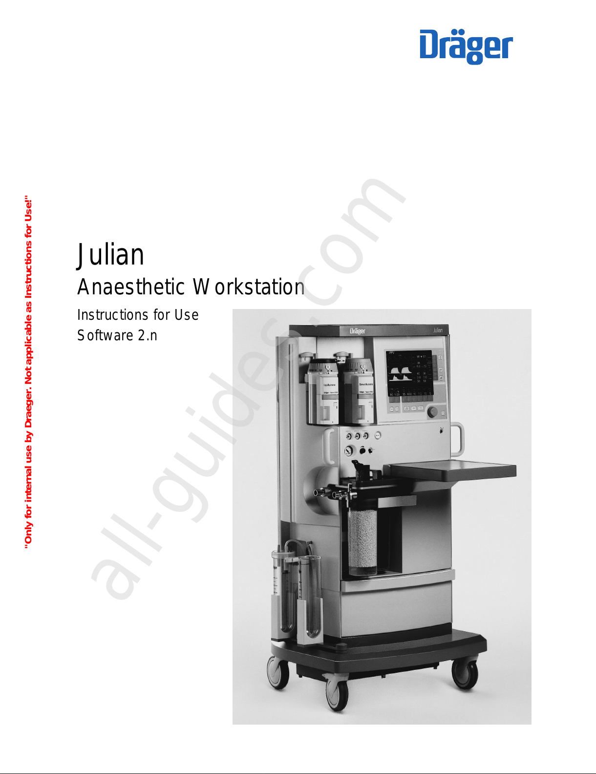
Julian
Anaesthetic Workstation
Instructions for Use
Software 2.n
1-36-96
"Only for internal use by Draeger. Not applicable as Instructions for Use!"
All manuals and user guides at all-guides.com
all-guides.com
Page 2

How to use these Instructions for Use
In the header is the subject…
of the main chapter.
Underneath is the title of the subchapter, to help you
find your way around quickly.
On each page…
the instructions for use
combining text with illustrations. The information is
translated directly into actions to enable the user to
learn „hands-on“ how to use the workstation.
Left-hand column: the text…
provides explanations and guides the user clearly and
ergonomically with brief directions on the use of the
product.
Bullet points indicate the steps to be followed, and
where there are several steps, numbers refer to the
illustration and indicate the sequence.
Right-hand column: the illustration…
provides the link with the text and serves as a guide
to the workstation. Points mentioned in the text are
emphasised and non-essential information is omitted.
Screen displays guide the user and confirm the steps
to be followed.
How to use these Instructions for Use
2
1 Press the »MAN/SPONT« key,
2 and confirm with the rotary knob.
Display (example):
O2 flush
– For flushing and rapidly filling the breathing
system and breathing bag with O2 while
bypassing the Vapor unit.
3 Press the »O2 +« button.
O2 flows into the breathing system without
anaesthetic gas as long as the button is held
down.
Julian
1
2
Operation
Selecting the ventilation mode
MAN/SPONT
Julian
D
3
MAN/SPONT
Pleth
40
0
CO
2
40 36
0.8 0.6
58 56
38
98 67
5.2 8
4.0030
Volumeter starten: Bestätigen!
O
2
SpO
2
N2O
Hal.
Fi
Fet
et
CO
2
AMV
Freq
Grenzen
CO
2
-Al.
aus/ein
Alarm
Info
Liste
Kurven
Konfig.
Frischgas O
2
+ N2O
O
2
%
L/min
VT
0.35
0
Volumeter
--s
--
05
10
0.5
1
Frischgas
intern
extern
"Only for internal use by Draeger. Not applicable as Instructions for Use!"
All manuals and user guides at all-guides.com
Page 3
Contents
3
Contents
Index 142
For Your Safety and that of Your Patients 5
Intended Use 7
Operating Concept 11
Before Using for the First Time 19
Preparation 21
Starting Up 25
Operation 35
Monitoring 55
Configuring in Standby Mode 81
Care 95
Julian as Wall-mounted Unit 113
Maintenance Intervals 115
What's what 125
Technical Data 131
Fault – Cause – Remedy 119
Abbreviations / Symbols 139
"Only for internal use by Draeger. Not applicable as Instructions for Use!"
All manuals and user guides at all-guides.com
Page 4

4
"Only for internal use by Draeger. Not applicable as Instructions for Use!"
All manuals and user guides at all-guides.com
Page 5
For Your Safety and that of Your
Patients
Strictly follow the Instructions for Use
Any use of the apparatus requires full understanding and
strict observation of these instructions.
The apparatus is only to be used for purposes specified
here.
Maintenance
The apparatus must be inspected and serviced regularly
by trained service personnel at six monthly intervals
(and a record kept).
Repair and general overhaul of the apparatus may only
be carried out by trained service personnel.
We recommend that a service contract be obtained with
DrägerService and that all repairs also be carried out by
them. Only authentic Dräger spare parts may be used for
maintenance.
Observe chapter "Maintenance Intervals".
Accessories
Do not use accessory parts other than those in the
order list.
Not for use in areas of explosion hazard
This apparatus is neither approved nor certified for use in
areas where combustible or explosive gas mixtures are
likely to occur.
Safe connection with other electrical equipment
Electrical connections to equipment which is not listed in
these Instructions for Use should only be made following
consultations with the respective manufacturers or an
expert.
Liability for proper function or damage
The liability for the proper function of the apparatus is
irrevocably transferred to the owner or operator to the
extent that the apparatus is serviced or repaired by
personnel not employed or authorized by DrägerService
or if the apparatus is used in a manner not conforming to
its intended use.
Dräger cannot be held responsible for damage caused
by non-compliance with the recommendations given
above. The warranty and liability provisions of the terms
of sale and delivery of Dräger are likewise not modified
by the recommendations given above.
Dräger Medizintechnik GmbH
For Your Safety and that of Your Patients
5
"Only for internal use by Draeger. Not applicable as Instructions for Use!"
All manuals and user guides at all-guides.com
Page 6

"Only for internal use by Draeger. Not applicable as Instructions for Use!"
All manuals and user guides at all-guides.com
all-guides.com
Page 7
Contents
Intended Use............................................................................................. 9
7
Intended Use
Contents
Intended Use
"Only for internal use by Draeger. Not applicable as Instructions for Use!"
All manuals and user guides at all-guides.com
Page 8

8
"Only for internal use by Draeger. Not applicable as Instructions for Use!"
All manuals and user guides at all-guides.com
Page 9
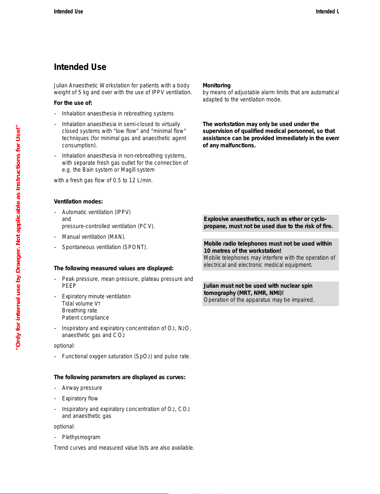
Intended Use
Julian Anaesthetic Workstation for patients with a body
weight of 5 kg and over with the use of IPPV ventilation.
For the use of:
– Inhalation anaesthesia in rebreathing systems
– Inhalation anaesthesia in semi-closed to virtually
closed systems with "low flow" and "minimal flow"
techniques (for minimal gas and anaesthetic agent
consumption).
– Inhalation anaesthesia in non-rebreathing systems,
with separate fresh gas outlet for the connection of
e.g. the Bain system or Magill system
with a fresh gas flow of 0.5 to 12 L/min.
Ventilation modes:
– Automatic ventilation (IPPV)
and
pressure-controlled ventilation (PCV).
– Manual ventilation (MAN).
– Spontaneous ventilation (SPONT).
The following measured values are displayed:
– Peak pressure, mean pressure, plateau pressure and
PEEP
– Expiratory minute ventilation
Tidal volume VT
Breathing rate
Patient compliance
– Inspiratory and expiratory concentration of O2, N2O,
anaesthetic gas and CO2
optional:
– Functional oxygen saturation (SpO2) and pulse rate.
The following parameters are displayed as curves:
– Airway pressure
– Expiratory flow
– Inspiratory and expiratory concentration of O2, CO2
and anaesthetic gas
optional:
– Plethysmogram
Trend curves and measured value lists are also available.
Monitoring
by means of adjustable alarm limits that are automatically
adapted to the ventilation mode.
The workstation may only be used under the
supervision of qualified medical personnel, so that
assistance can be provided immediately in the event
of any malfunctions.
Explosive anaesthetics, such as ether or cyclo-
propane, must not be used due to the risk of fire.
Mobile radio telephones must not be used within
10 metres of the workstation!
Mobile telephones may interfere with the operation of
electrical and electronic medical equipment.
Julian must not be used with nuclear spin
tomography (MRT, NMR, NMI)!
Operation of the apparatus may be impaired.
Intended Use
9
Intended Use
"Only for internal use by Draeger. Not applicable as Instructions for Use!"
All manuals and user guides at all-guides.com
Page 10

10
"Only for internal use by Draeger. Not applicable as Instructions for Use!"
All manuals and user guides at all-guides.com
Page 11
Contents
Screen ergonomics.................................................................................12
Selecting / setting ventilation parameters..................................................14
Selecting / setting monitoring functions.....................................................15
Screen layout..........................................................................................16
Three basic screens for monitoring...........................................................17
The standard screen.................................................................................17
The data screen....................................................................................... 17
The trend screen......................................................................................18
Operating Concept
Contents
11
Operating Concept
"Only for internal use by Draeger. Not applicable as Instructions for Use!"
All manuals and user guides at all-guides.com
all-guides.com
Page 12
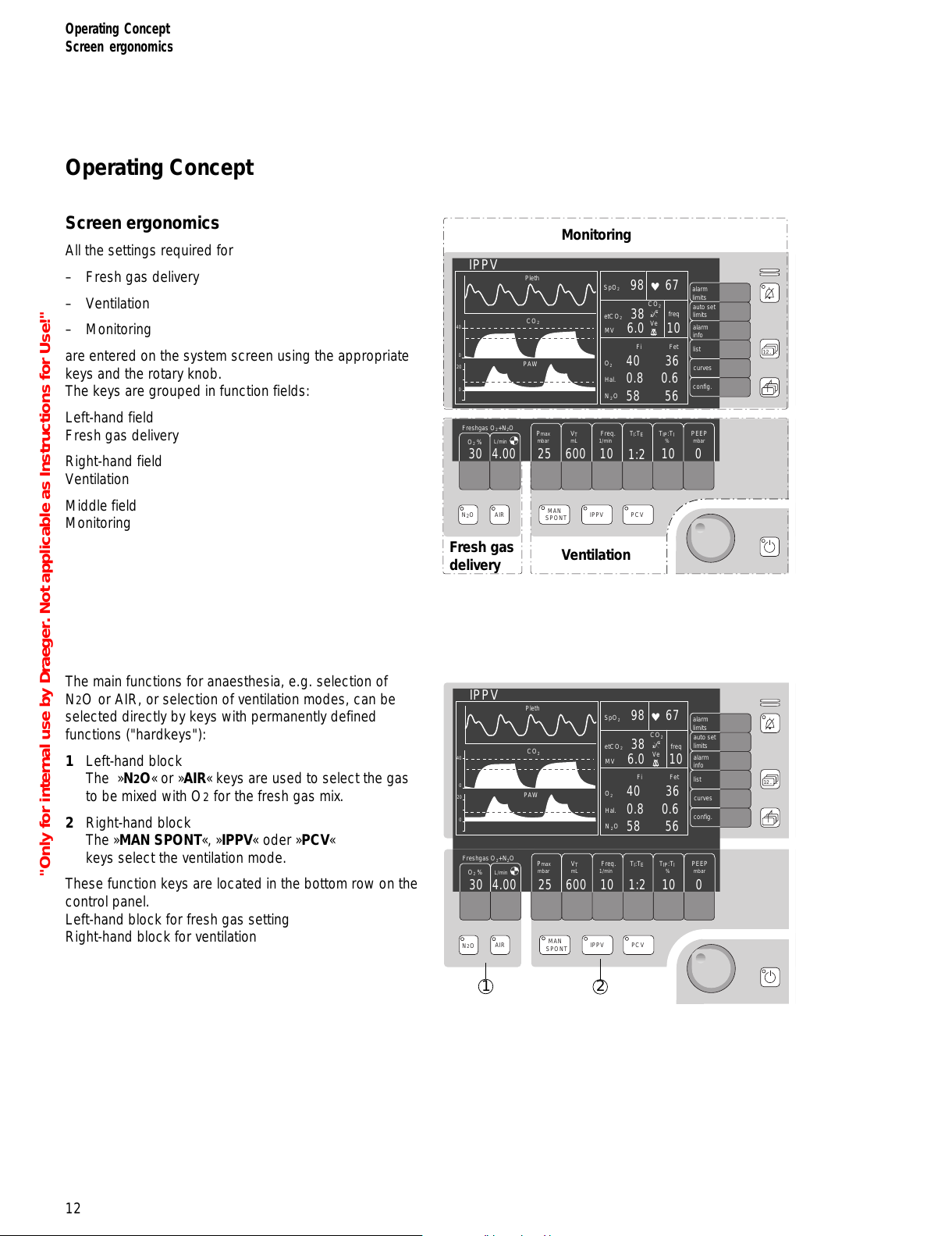
Operating Concept
Screen ergonomics
All the settings required for
– Fresh gas delivery
– Ventilation
– Monitoring
are entered on the system screen using the appropriate
keys and the rotary knob.
The keys are grouped in function fields:
Left-hand field
Fresh gas delivery
Right-hand field
Ventilation
Middle field
Monitoring
The main functions for anaesthesia, e.g. selection of
N2O or AIR, or selection of ventilation modes, can be
selected directly by keys with permanently defined
functions ("hardkeys"):
1 Left-hand block
The »N2O« or »AIR« keys are used to select the gas
to be mixed with O2 for the fresh gas mix.
2 Right-hand block
The »MAN SPONT«, »IPPV« oder »PCV«
keys select the ventilation mode.
These function keys are located in the bottom row on the
control panel.
Left-hand block for fresh gas setting
Right-hand block for ventilation
Operating Concept
Screen ergonomics
12
.
12...
.
NO
2
AIR
MAN
SPONT
IPPV PCV
Monitoring
Ventilation
Fresh gas
delivery
Pleth
IPPV
alarm
limits
auto set
limits
alarm
info
list
curves
CO
2
40
0
PAW
0
20
config.
O
2
SpO
2
N2O
Hal.
40 36
0.8 0.6
58 56
Fi
Fet
etCO
2
38
98 67
6.0 10
MV
freq
600
V
T
mL
10
1:2
10 0
PEEP
mbar
Freq.
1/min
TI:TETIP:TI
%
25
Pmax
mbar
Freshgas O2+N2O
4.00
O
2
%
L/min
30
_
CO
2
Ve
.
12...
.
NO
2
AIR
MAN
SPONT
IPPV PCV
Pleth
IPPV
alarm
limits
auto set
limits
alarm
info
list
curves
CO
2
40
0
PAW
0
20
config.
O
2
SpO
2
N2O
Hal.
40 36
0.8 0.6
58 56
Fi
Fet
etCO
2
38
98 67
6.0 10
MV
freq
600
V
T
mL
10
1:2
10 0
PEEP
mbar
Freq.
1/min
TI:TETIP:TI
%
25
Pmax
mbar
Freshgas O2+N2O
4.00
O
2
%
L/min
30
1
2
_
CO
2
Ve
"Only for internal use by Draeger. Not applicable as Instructions for Use!"
All manuals and user guides at all-guides.com
Page 13
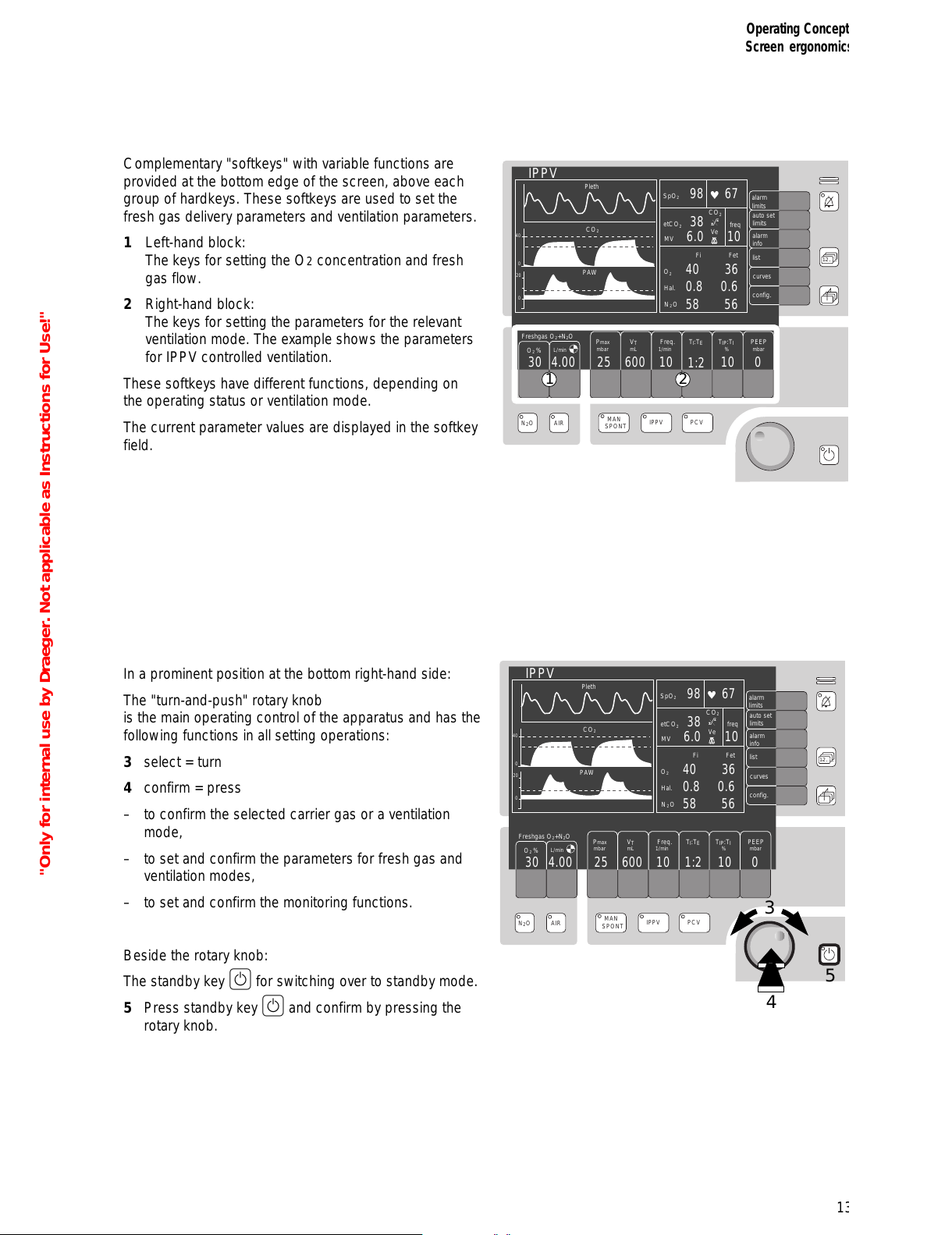
Complementary "softkeys" with variable functions are
provided at the bottom edge of the screen, above each
group of hardkeys. These softkeys are used to set the
fresh gas delivery parameters and ventilation parameters.
1 Left-hand block:
The keys for setting the O2 concentration and fresh
gas flow.
2 Right-hand block:
The keys for setting the parameters for the relevant
ventilation mode. The example shows the parameters
for IPPV controlled ventilation.
These softkeys have different functions, depending on
the operating status or ventilation mode.
The current parameter values are displayed in the softkey
field.
In a prominent position at the bottom right-hand side:
The "turn-and-push" rotary knob
is the main operating control of the apparatus and has the
following functions in all setting operations:
3 select = turn
4 confirm = press
– to confirm the selected carrier gas or a ventilation
mode,
– to set and confirm the parameters for fresh gas and
ventilation modes,
– to set and confirm the monitoring functions.
Beside the rotary knob:
The standby key E for switching over to standby mode.
5 Press standby key E and confirm by pressing the
rotary knob.
13
Operating Concept
Screen ergonomics
.
12...
.
NO
2
AIR
MAN
SPONT
IPPV PCV
Pleth
IPPV
alarm
limits
auto set
limits
alarm
info
list
curves
CO
2
40
0
PAW
0
20
config.
O
2
SpO
2
N2O
Hal.
40 36
0.8 0.6
58 56
Fi
Fet
etCO
2
38
98 67
6.0 10
MV
freq
600
V
T
mL
10
1:2
10 0
PEEP
mbar
Freq.
1/min
TI:TETIP:TI
%
25
Pmax
mbar
Freshgas O2+N2O
4.00
O
2
%
L/min
30
1 2
_
CO
2
Ve
.
12...
.
NO
2
AIR
MAN
SPONT
IPPV PCV
Pleth
IPPV
alarm
limits
auto set
limits
alarm
info
list
curves
CO
2
40
0
PAW
0
20
config.
O
2
SpO
2
N2O
Hal.
40 36
0.8 0.6
58 56
Fi
Fet
etCO
2
38
98 67
6.0 10
MV
freq
600
V
T
mL
10
1:2
10 0
PEEP
mbar
Freq.
1/min
TI:TETIP:TI
%
25
Pmax
mbar
Freshgas O2+N2O
4.00
O
2
%
L/min
30
3
5
4
_
CO
2
Ve
"Only for internal use by Draeger. Not applicable as Instructions for Use!"
All manuals and user guides at all-guides.com
Page 14
Operating Concept
Screen ergonomics
14
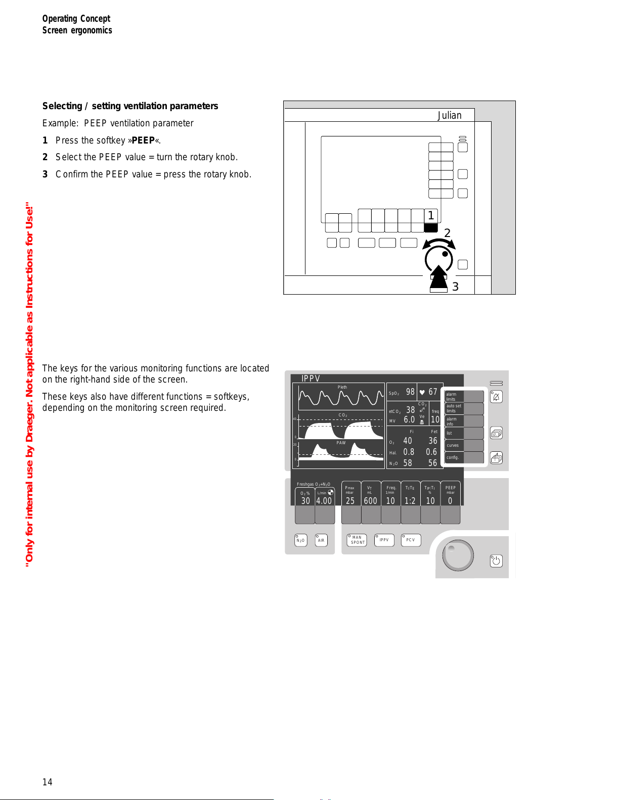
Selecting / setting ventilation parameters
Example: PEEP ventilation parameter
1 Press the softkey »PEEP«.
2 Select the PEEP value = turn the rotary knob.
3 Confirm the PEEP value = press the rotary knob.
The keys for the various monitoring functions are located
on the right-hand side of the screen.
These keys also have different functions = softkeys,
depending on the monitoring screen required.
Julian
1
2
3
.
12...
.
NO
2
AIR
MAN
SPONT
IPPV PCV
Pleth
IPPV
alarm
limits
auto set
limits
alarm
info
list
curves
CO
2
40
0
PAW
0
20
config.
O
2
SpO
2
N2O
Hal.
40 36
0.8 0.6
58 56
Fi
Fet
etCO
2
38
98 67
6.0 10
MV
freq
600
V
T
mL
10
1:2
10 0
PEEP
mbar
Freq.
1/min
TI:TETIP:TI
%
25
Pmax
mbar
Freshgas O2+N2O
4.00
O
2
%
L/min
30
_
CO
2
Ve
"Only for internal use by Draeger. Not applicable as Instructions for Use!"
All manuals and user guides at all-guides.com
Page 15

15
Operating Concept
Screen ergonomics
Selecting / setting monitoring functions
For example, to change the lower alarm limit of the end-
tidal CO2 concentration.
1 Press the »alarm limits« softkey. The alarm limits
menu is displayed on the screen.
● Select the alarm limit value = turn the rotary knob.
Confirm the selection = press the rotary knob.
The limit value is highlighted.
Example: lower alarm limit etCO2: <30
● Set the alarm limit value = turn the rotary knob.
● Confirm the new alarm limit = press the rotary knob.
The cursor returns to the zsymbol.
Julian
1
Pleth
IPPV
CO2
40
0
PAW
600 10
1:2
10 0251.0050
98
67
38
6.0
29
0.8
--
95
3.0
--
20
1.0
0.0
40
8
120
50
--
Select limit: Turn and confirm ! !
42
30
0
20
FiO
2
FiHal.
PAW
SpO
2
etCO
2
MV
alarm
limits
auto set
limits
alarm
info
list
curves
config.
O
2
%
L/min
PEEP
mbar
Freq.
1/min
V
T
mL
TI:TETIP:T
I
%
Pmax
mbar
Freshgas O
2
+ N2O
Pleth
IPPV
CO
2
40
0
600 10
1:2
10 0251.0050
98
67
38
6.0
29
0.8
--
95
3.0
--
20
1.0
0.0
40
8
120
50
--
Adjust limit value: Turn and confirm !
42
30
PAW
0
20
FiO
2
FiHal.
PAW
SpO
2
etCO
2
MV
alarm
limits
auto set
limits
alarm
info
list
curves
config.
O
2
%
L/min
PEEP
mbar
Freq.
1/min
V
T
mL
TI:TETIP:T
I
%
Pmax
mbar
Freshgas O2 + N2O
"Only for internal use by Draeger. Not applicable as Instructions for Use!"
All manuals and user guides at all-guides.com
Page 16
Operating Concept
Screen ergonomics
Screen layout
16
Pleth
IPPV
alarm
limits
auto set
limits
alarm
info
list
curves
CO
2
40
0
PAW
0
20
config.
O
2
SpO
2
N2O
Hal.
40 36
0.8 0.6
58 56
Fi
Fet
etCO
2
38
98 67
6.0 10
MV
freq
600
V
T
mL
10
1:2
10 0
PEEP
mbar
Freq.
1/min
TI:TETIP:TI
%
25
Pmax
mbar
Freshgas O2+N2O
4.00
O
2
%
L/min
30
_
CO
2
Ve
➀ ➁ ➂ ➃
➄ ➅ ➆ ➇
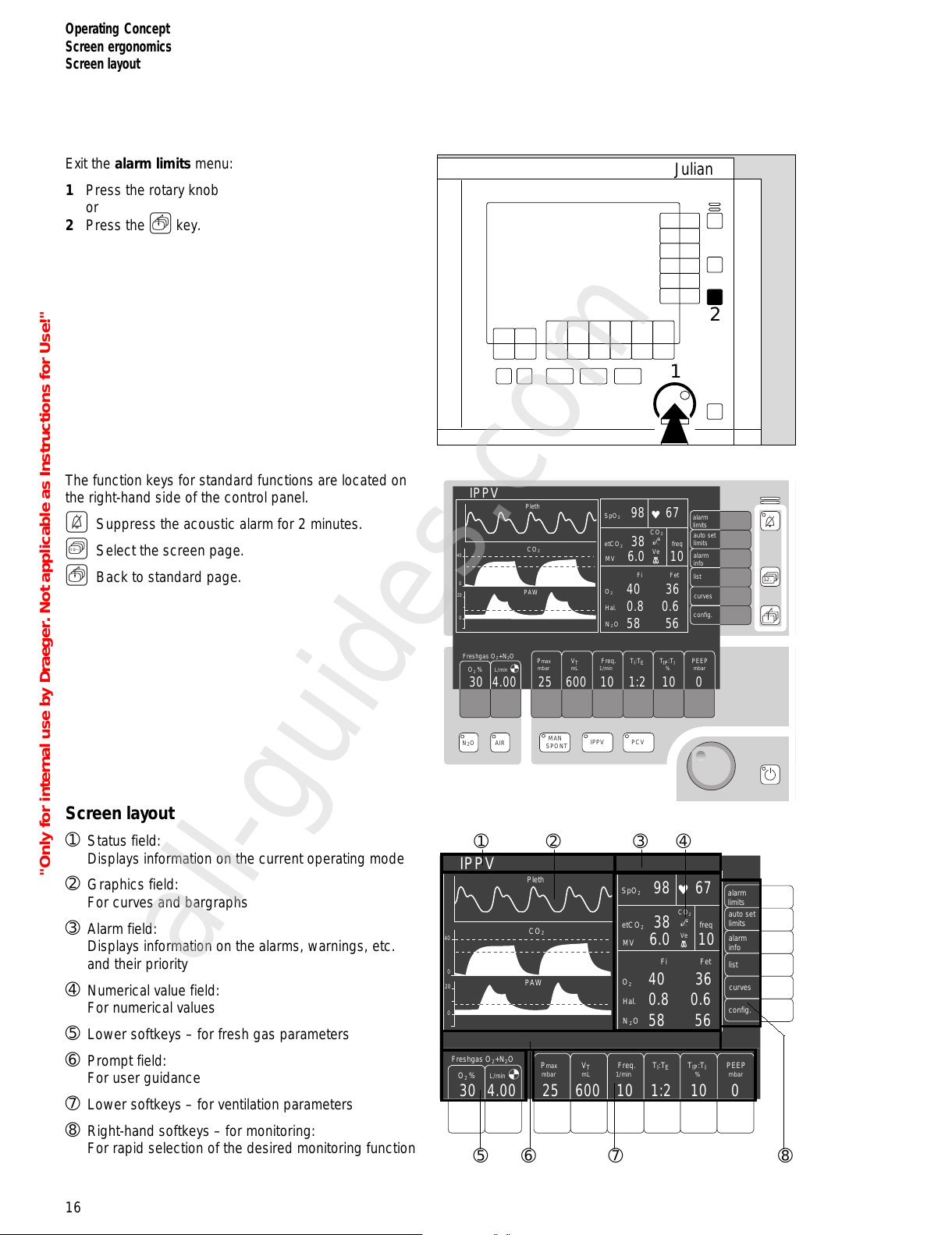
Exit the alarm limits menu:
1 Press the rotary knob
or
2 Press the Q key.
The function keys for standard functions are located on
the right-hand side of the control panel.
G Suppress the acoustic alarm for 2 minutes.
S Select the screen page.
Q Back to standard page.
Screen layout
➀ Status field:
Displays information on the current operating mode
➁ Graphics field:
For curves and bargraphs
➂ Alarm field:
Displays information on the alarms, warnings, etc.
and their priority
➃ Numerical value field:
For numerical values
➄ Lower softkeys – for fresh gas parameters
➅ Prompt field:
For user guidance
➆ Lower softkeys – for ventilation parameters
➇ Right-hand softkeys – for monitoring:
For rapid selection of the desired monitoring function
.
12...
.
NO
2
AIR
MAN
SPONT
IPPV PCV
Pleth
IPPV
alarm
limits
auto set
limits
alarm
info
list
curves
CO
2
40
0
PAW
0
20
config.
O
2
SpO
2
N2O
Hal.
40 36
0.8 0.6
58 56
Fi
Fet
etCO
2
38
98 67
6.0 10
MV
freq
600
V
T
mL
10
1:2
10 0
PEEP
mbar
Freq.
1/min
TI:TETIP:TI
%
25
Pmax
mbar
Freshgas O2+N2O
4.00
O
2
%
L/min
30
_
CO
2
Ve
Julian
2
1
"Only for internal use by Draeger. Not applicable as Instructions for Use!"
All manuals and user guides at all-guides.com
all-guides.com
Page 17
17
Operating Concept
Screen layout
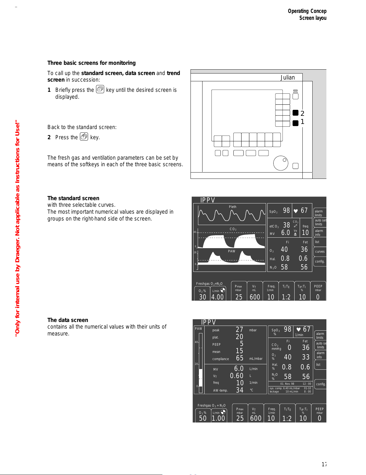
Three basic screens for monitoring
To call up the standard screen, data screen and trend
screen in succession:
1 Briefly press the S key until the desired screen is
displayed.
Back to the standard screen:
2 Press the Q key.
The fresh gas and ventilation parameters can be set by
means of the softkeys in each of the three basic screens.
The standard screen
with three selectable curves.
The most important numerical values are displayed in
groups on the right-hand side of the screen.
The data screen
contains all the numerical values with their units of
measure.
Julian
2
1
Pleth
IPPV
alarm
limits
auto set
limits
alarm
info
list
curves
CO
2
40
0
PAW
0
20
config.
O
2
SpO
2
N2O
Hal.
40 36
0.8 0.6
58 56
Fi
Fet
etCO
2
38
98 67
6.0 10
MV
freq
600
V
T
mL
10
1:2
10 0
PEEP
mbar
Freq.
1/min
TI:TETIP:TI
%
25
Pmax
mbar
Freshgas O2+N2O
4.00
O
2
%
L/min
30
_
CO
2
Ve
IPPV
PAW
40
20
0
600 10
1:2
10 0251.0050
O
2
%
N
2
O
%
Hal.
%
036
40 33
0.8 0.6
58 56
Fi
Fet
CO
2
mmHg
98 67
6.0
0.60
10
27
20
5
15
65
MV
V
T
freq
peak
plat.
PEEP
mean
compliance
mbar
mL/mbar
L/min
L
34
AW-temp.
°C
1/min
01. Nov. 98
sys. comp. 6.40 mL/mbar
leckage 10 mL/min
01-10
8 : 00
12 : 00
SpO
2
%
1/min
alarm
limits
auto se
t
limits
alarm
info
list
config.
Freshgas O
2
+ N2O
O
2
%
L/min
PEEP
mbar
Freq.
1/min
V
T
mL
TI:TETIP:T
I
%
Pmax
mbar
"Only for internal use by Draeger. Not applicable as Instructions for Use!"
All manuals and user guides at all-guides.com
Page 18
Operating Concept
Screen layout
18
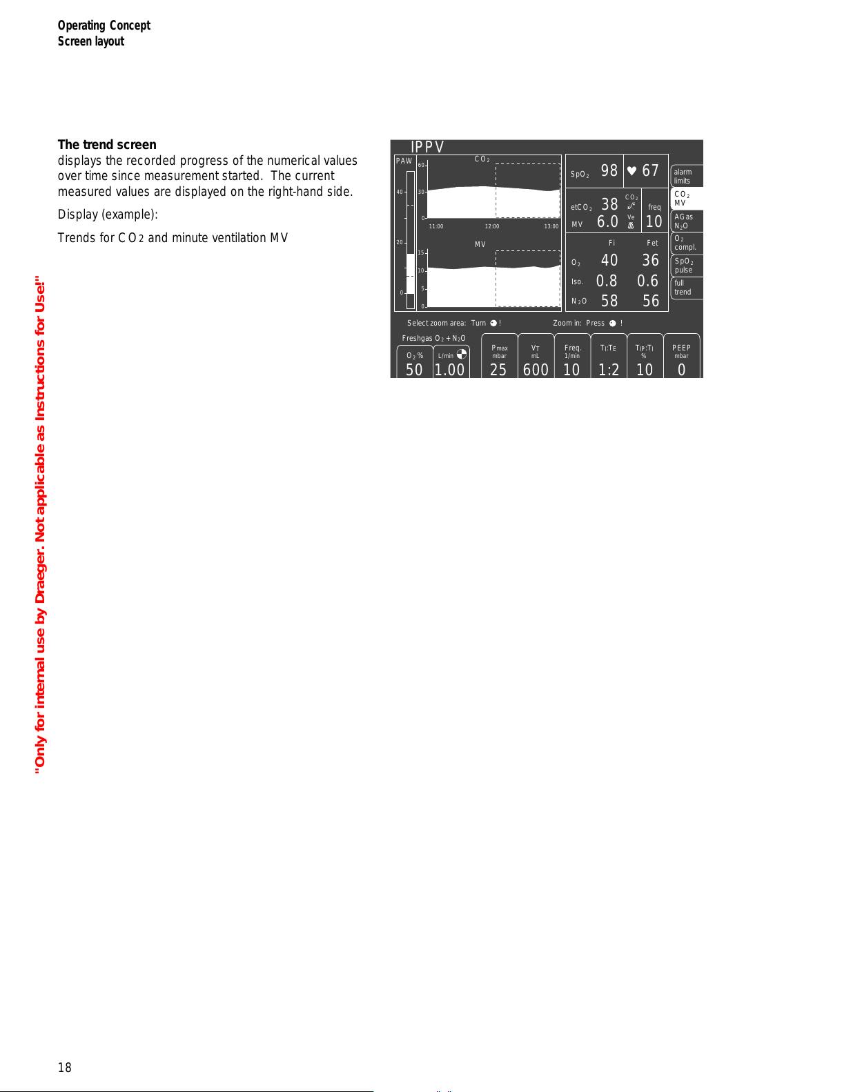
The trend screen
displays the recorded progress of the numerical values
over time since measurement started. The current
measured values are displayed on the right-hand side.
Display (example):
Trends for CO2 and minute ventilation MV
IPPV
40 36
0.8 0.6
58 56
38
98 67
6.0 10
600 10
1:2
10 0251.0050
PAW
40
20
0
11:00 12:00 13:00
60
30
0
15
10
5
0
Select zoom area:
Turn !
Zoom in: Press !
CO
2
MV
O
2
SpO
2
N2O
Iso.
Fi
Fet
etCO
2
MV
freq
alarm
limits
AGas
N
2
O
CO
2
MV
O
2
compl.
SpO
2
pulse
full
trend
O
2
%
L/min
PEEP
mbar
Freq.
1/min
V
T
mL
TI:TETIP:T
I
%
Pmax
mbar
Freshgas O
2
+ N2O
_
CO
2
Ve
"Only for internal use by Draeger. Not applicable as Instructions for Use!"
All manuals and user guides at all-guides.com
Page 19
Contents
Charging the battery for emergency operation......................................20
When Julian is not in use........................................................................ 20
19
Before Using for the First Time
Contents
Before Using for the First Time
"Only for internal use by Draeger. Not applicable as Instructions for Use!"
All manuals and user guides at all-guides.com
Page 20

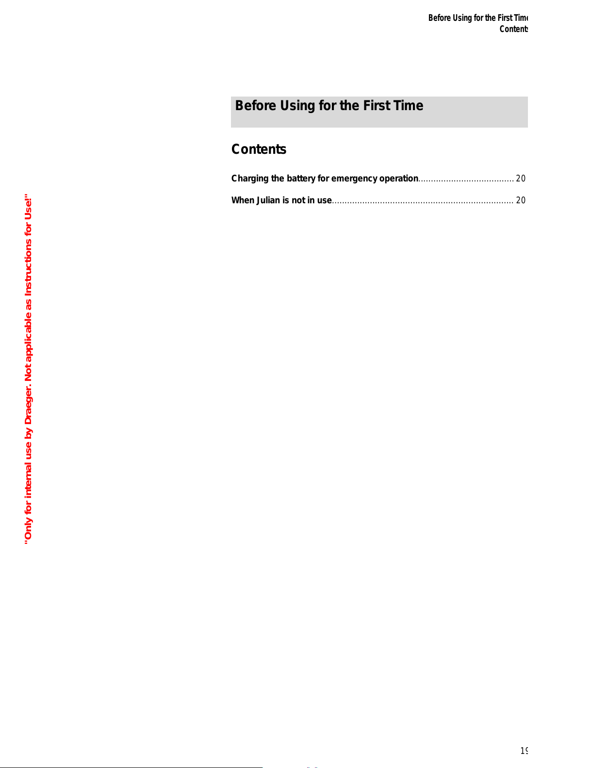
Before Using for the First Time
Fit the enclosed O2 sensor,
page 117 "Replacing O2 sensor"
Fit the flow sensor, page 106
Charging the battery for emergency
operation
Julian has a built-in uninterruptible power supply UPS
which maintains the power supply for 30 minutes in the
event of a mains failure, provided that the battery is
charged.
The switch-over to the battery-powered UPS is automatic
and is indicated on the screen by the message:
POWER FAIL!
The battery recharges automatically when the workstation
is plugged into the mains.
The battery must be charged for 10 hours before using
the Workstation for the first time.
● Plug the mains plug of the Julian workstation into the
mains socket. The mains voltage must correspond to
the voltage specified on the nameplate.
1 The green LED
NN
NN
lights up.
● Leave Julian connected to the mains for 10 hours.
The workstation does not have to be switched on.
The devices connected to auxiliary power sockets will
not be powered by the UPS in the event of a power
failure.
When Julian is not in use
● Charge battery at least every 4 weeks.
Allowing it to run down can lead to damage.
If Julian is out of use for an extended period:
● Leave the workstation connected to the mains at all
times.
1 The green LED
NN
NN
is lit.
20
Before Using for the First Time
Charging the battery for emergency operation
When Julian is not in use
1
"Only for internal use by Draeger. Not applicable as Instructions for Use!"
All manuals and user guides at all-guides.com
Page 21
Contents
Connecting the gas supply.....................................................................22
Connecting the backup gas cylinders for O2 and N2O .............................23
Caution when handling O2 cylinders.........................................................23
Connecting the anaesthetic gas scavenging system.............................23
Connecting the power supply.................................................................24
Connecting auxiliary systems....................................................................24
Equipotential bonding...............................................................................24
Connecting the power supply...................................................................24
21
Preparation
Contents
Preparation
"Only for internal use by Draeger. Not applicable as Instructions for Use!"
All manuals and user guides at all-guides.com
all-guides.com
Page 22
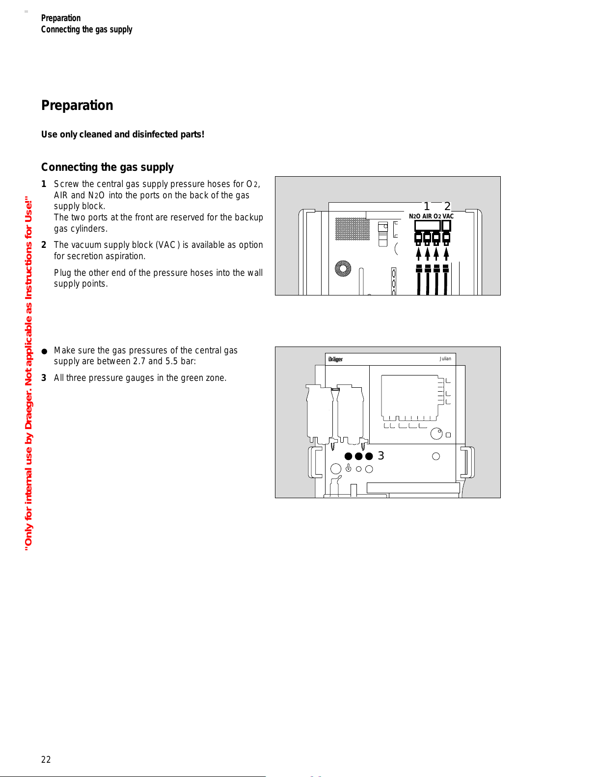
Preparation
Use only cleaned and disinfected parts!
Connecting the gas supply
1 Screw the central gas supply pressure hoses for O2,
AIR and N2O into the ports on the back of the gas
supply block.
The two ports at the front are reserved for the backup
gas cylinders.
2 The vacuum supply block (VAC) is available as option
for secretion aspiration.
Plug the other end of the pressure hoses into the wall
supply points.
● Make sure the gas pressures of the central gas
supply are between 2.7 and 5.5 bar:
3 All three pressure gauges in the green zone.
22
Preparation
Connecting the gas supply
N2O AIR O2 VAC
12
Julian
D
3
"Only for internal use by Draeger. Not applicable as Instructions for Use!"
All manuals and user guides at all-guides.com
Page 23
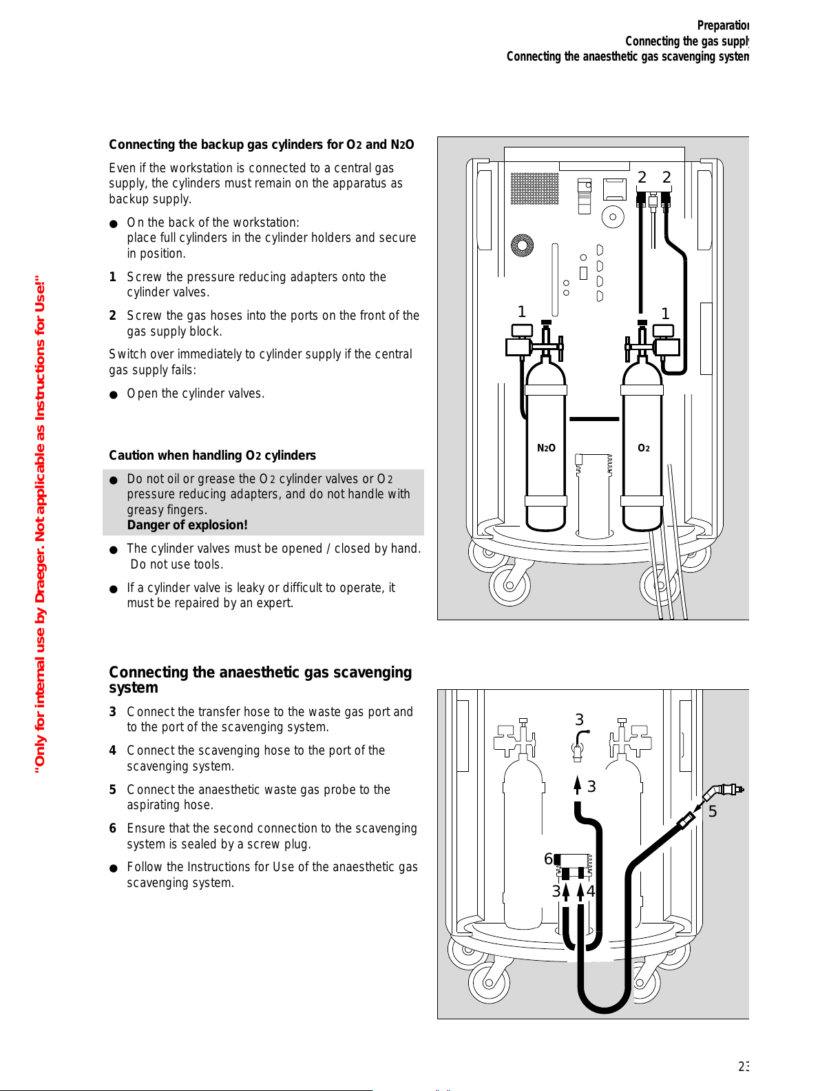
Connecting the backup gas cylinders for O2 and N2O
Even if the workstation is connected to a central gas
supply, the cylinders must remain on the apparatus as
backup supply.
● On the back of the workstation:
place full cylinders in the cylinder holders and secure
in position.
1 Screw the pressure reducing adapters onto the
cylinder valves.
2 Screw the gas hoses into the ports on the front of the
gas supply block.
Switch over immediately to cylinder supply if the central
gas supply fails:
● Open the cylinder valves.
Caution when handling O2 cylinders
● Do not oil or grease the O2 cylinder valves or O2
pressure reducing adapters, and do not handle with
greasy fingers.
Danger of explosion!
● The cylinder valves must be opened / closed by hand.
Do not use tools.
● If a cylinder valve is leaky or difficult to operate, it
must be repaired by an expert.
Connecting the anaesthetic gas scavenging
system
3 Connect the transfer hose to the waste gas port and
to the port of the scavenging system.
4 Connect the scavenging hose to the port of the
scavenging system.
5 Connect the anaesthetic waste gas probe to the
aspirating hose.
6 Ensure that the second connection to the scavenging
system is sealed by a screw plug.
● Follow the Instructions for Use of the anaesthetic gas
scavenging system.
23
Preparation
Connecting the gas supply
Connecting the anaesthetic gas scavenging system
N2O
1
1
O2
22
6
3
3
5
4
3
"Only for internal use by Draeger. Not applicable as Instructions for Use!"
All manuals and user guides at all-guides.com
Page 24
Connecting the power supply
Connecting auxiliary systems
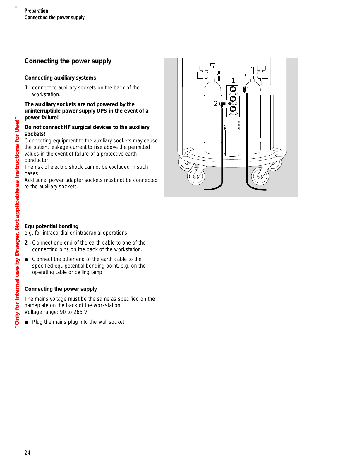
1 connect to auxiliary sockets on the back of the
workstation.
The auxiliary sockets are not powered by the
uninterruptible power supply UPS in the event of a
power failure!
Do not connect HF surgical devices to the auxiliary
sockets!
Connecting equipment to the auxiliary sockets may cause
the patient leakage current to rise above the permitted
values in the event of failure of a protective earth
conductor.
The risk of electric shock cannot be excluded in such
cases.
Additional power adapter sockets must not be connected
to the auxiliary sockets.
Equipotential bonding
e.g. for intracardial or intracranial operations.
2 Connect one end of the earth cable to one of the
connecting pins on the back of the workstation.
● Connect the other end of the earth cable to the
specified equipotential bonding point, e.g. on the
operating table or ceiling lamp.
Connecting the power supply
The mains voltage must be the same as specified on the
nameplate on the back of the workstation.
Voltage range: 90 to 265 V
● Plug the mains plug into the wall socket.
24
Preparation
Connecting the power supply
1
2
"Only for internal use by Draeger. Not applicable as Instructions for Use!"
All manuals and user guides at all-guides.com
Page 25
Contents
Checking the workstation against the checklist.................................... 26
Switching on............................................................................................26
Gas pressures.........................................................................................29
Central gas supply................................................................................... 29
Backup gas cylinders............................................................................... 29
Suction system.........................................................................................30
O2 flush .................................................................................................. 30
O2 emergency metering........................................................................... 30
Preparing Julian for the self-test................................................................31
Self-test...................................................................................................31
Electronics...............................................................................................31
Fresh gas mixer........................................................................................31
Ventilator and breathing system ...............................................................31
System compliance................................................................................ 32
Leakage...................................................................................................32
Emergency start......................................................................................33
25
Starting Up
Contents
Starting Up
"Only for internal use by Draeger. Not applicable as Instructions for Use!"
All manuals and user guides at all-guides.com
Page 26
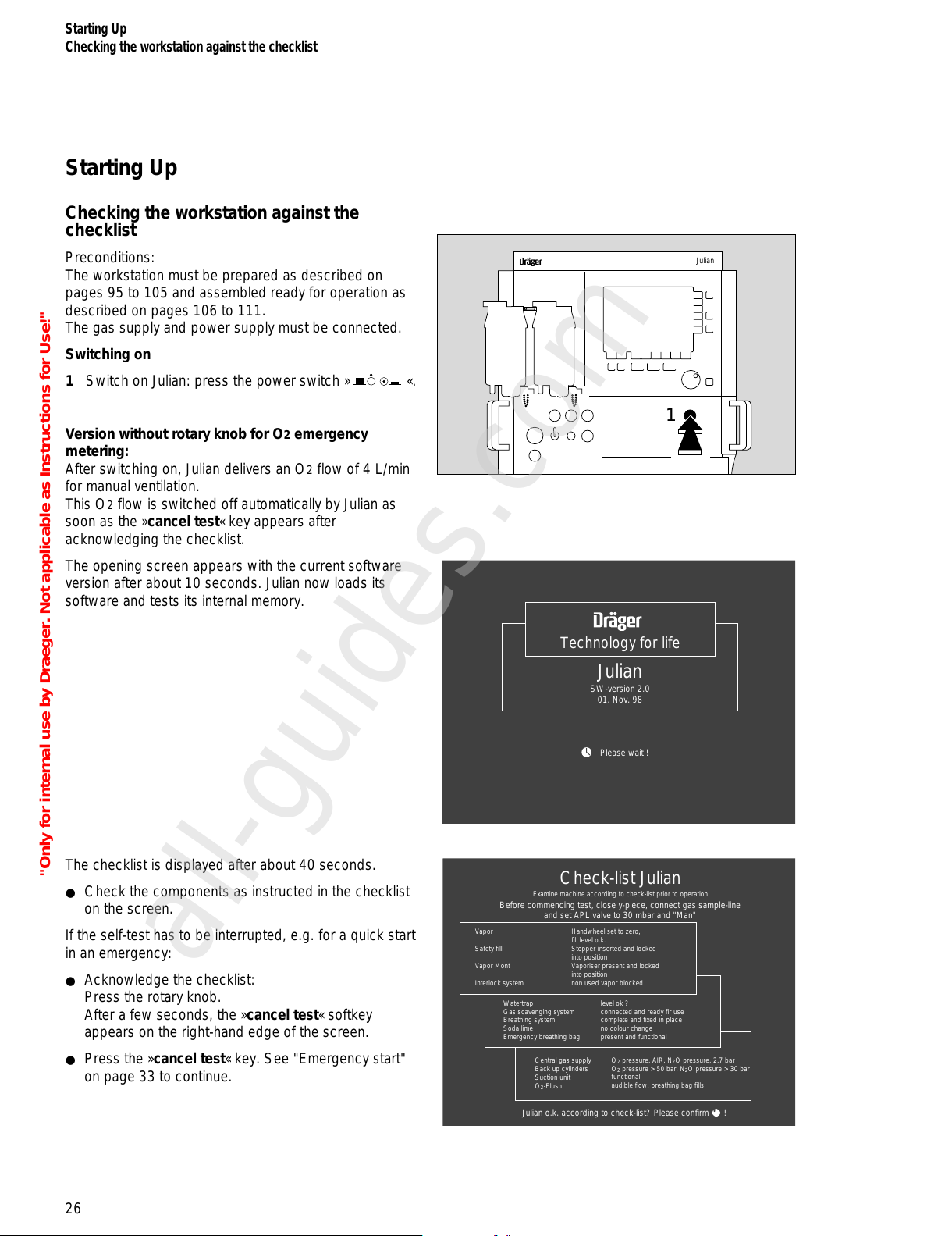
Starting Up
Checking the workstation against the
checklist
Preconditions:
The workstation must be prepared as described on
pages 95 to 105 and assembled ready for operation as
described on pages 106 to 111.
The gas supply and power supply must be connected.
Switching on
1 Switch on Julian: press the power switch » «.
Version without rotary knob for O2 emergency
metering:
After switching on, Julian delivers an O2 flow of 4 L/min
for manual ventilation.
This O2 flow is switched off automatically by Julian as
soon as the »cancel test« key appears after
acknowledging the checklist.
The opening screen appears with the current software
version after about 10 seconds. Julian now loads its
software and tests its internal memory.
The checklist is displayed after about 40 seconds.
● Check the components as instructed in the checklist
on the screen.
If the self-test has to be interrupted, e.g. for a quick start
in an emergency:
● Acknowledge the checklist:
Press the rotary knob.
After a few seconds, the »cancel test« softkey
appears on the right-hand edge of the screen.
● Press the »cancel test« key. See "Emergency start"
on page 33 to continue.
Starting Up
Checking the workstation against the checklist
26
Julian
D
1
Technology for life
SW-version 2.0
01. Nov. 98
Please wait !
Julian
Check-list Julian
Vapor
Safety fill
Vapor Mont
Interlock system
Handwheel set to zero,
fill level o.k.
Stopper inserted and locked
into position
Vaporiser present and locked
into position
non used vapor blocked
Watertrap
Gas scavenging system
Breathing system
Soda lime
Emergency breathing bag
level ok ?
connected and ready fir use
complete and fixed in place
no colour change
present and functional
Central gas supply
Back up cylinders
Suction unit
O
2
-Flush
O
2
pressure, AIR, N2O pressure, 2,7 bar
O
2
pressure > 50 bar, N2O pressure > 30 bar
functional
audible flow, breathing bag fills
Julian o.k. according to check-list? Please confirm !
Examine machine according to check-list prior to operation
Before commencing test, close y-piece, connect gas sample-line
and set APL valve to 30 mbar and "Man"
"Only for internal use by Draeger. Not applicable as Instructions for Use!"
All manuals and user guides at all-guides.com
all-guides.com
Page 27
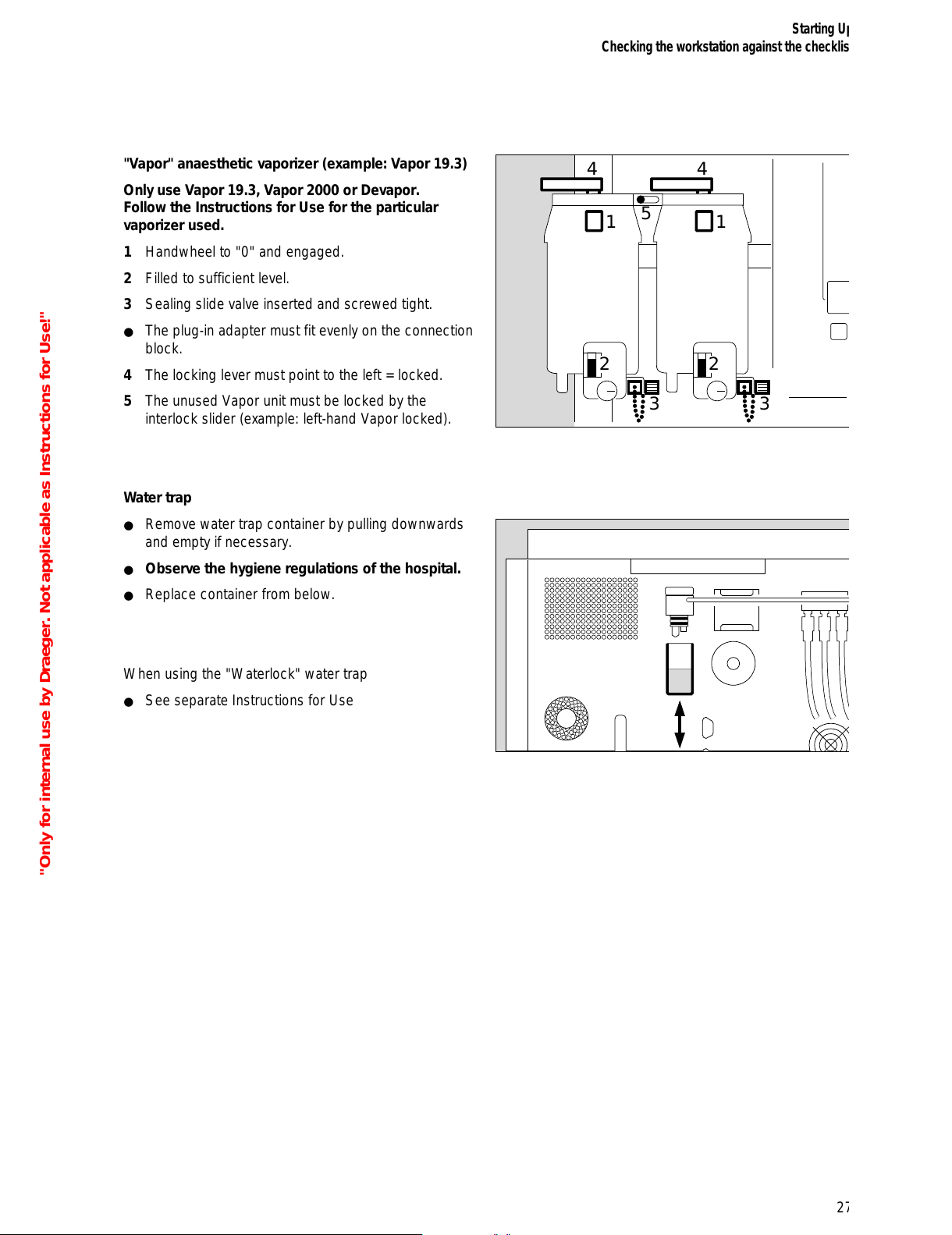
"Vapor" anaesthetic vaporizer (example: Vapor 19.3)
Only use Vapor 19.3, Vapor 2000 or Devapor.
Follow the Instructions for Use for the particular
vaporizer used.
1 Handwheel to "0" and engaged.
2 Filled to sufficient level.
3 Sealing slide valve inserted and screwed tight.
● The plug-in adapter must fit evenly on the connection
block.
4 The locking lever must point to the left = locked.
5 The unused Vapor unit must be locked by the
interlock slider (example: left-hand Vapor locked).
Water trap
● Remove water trap container by pulling downwards
and empty if necessary.
● Observe the hygiene regulations of the hospital.
● Replace container from below.
When using the "Waterlock" water trap
● See separate Instructions for Use
27
Starting Up
Checking the workstation against the checklist
33
4
5
4
1
2 2
1
"Only for internal use by Draeger. Not applicable as Instructions for Use!"
All manuals and user guides at all-guides.com
Page 28
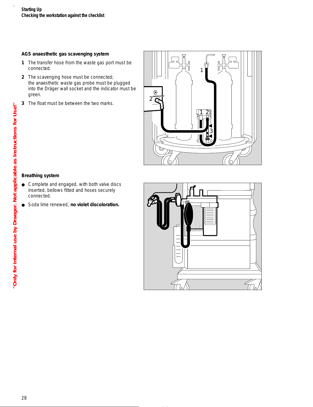
AGS anaesthetic gas scavenging system
1 The transfer hose from the waste gas port must be
connected.
2 The scavenging hose must be connected;
the anaesthetic waste gas probe must be plugged
into the Dräger wall socket and the indicator must be
green.
3 The float must be between the two marks.
Breathing system
● Complete and engaged, with both valve discs
inserted, bellows fitted and hoses securely
connected.
● Soda lime renewed, no violet discoloration.
28
Starting Up
Checking the workstation against the checklist
3
21
2
1
"Only for internal use by Draeger. Not applicable as Instructions for Use!"
All manuals and user guides at all-guides.com
Page 29

Emergency ventilating bag
Example: Dräger Resutator 2000
● Ready for operation.
Central gas supply
Gas pressures:
1 All pressure gauges in the green zone.
Backup gas cylinders
2 Slowly open the cylinder valves.
Check the cylinder pressure gauges:
3 O2 pressure greater than 50 bar,
4 N2O pressure greater than 30 bar.
2 Reclose the cylinder valves.
29
Starting Up
Checking the workstation against the checklist
2
2
4
3
N2O O2
Julian
D
3
"Only for internal use by Draeger. Not applicable as Instructions for Use!"
All manuals and user guides at all-guides.com
Page 30
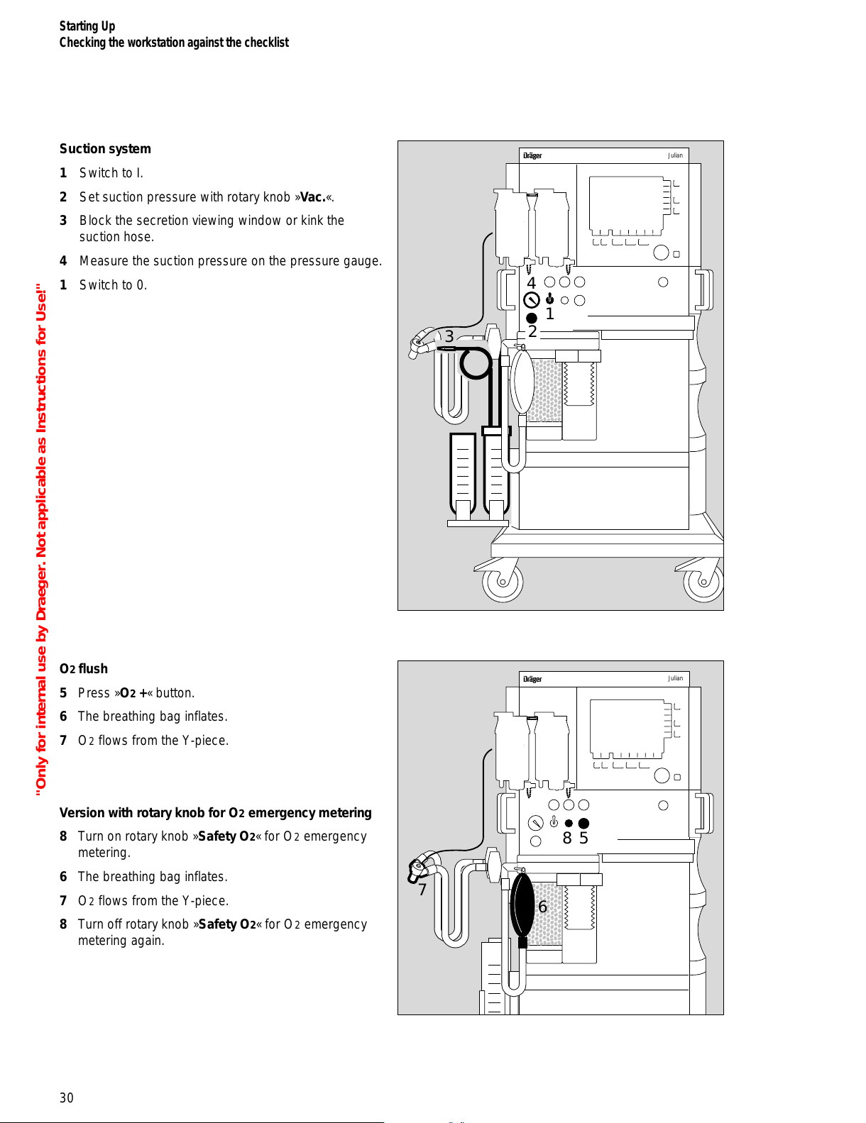
Suction system
1 Switch to I.
2 Set suction pressure with rotary knob »Vac.«.
3 Block the secretion viewing window or kink the
suction hose.
4 Measure the suction pressure on the pressure gauge.
1 Switch to 0.
O2 flush
5 Press »O2 +« button.
6 The breathing bag inflates.
7 O2 flows from the Y-piece.
Version with rotary knob for O2 emergency metering
8 Turn on rotary knob »Safety O2« for O2 emergency
metering.
6 The breathing bag inflates.
7 O2 flows from the Y-piece.
8 Turn off rotary knob »Safety O2« for O2 emergency
metering again.
30
Starting Up
Checking the workstation against the checklist
7
Julian
D
6
5
8
Julian
D
4
1
3
2
"Only for internal use by Draeger. Not applicable as Instructions for Use!"
All manuals and user guides at all-guides.com
Page 31

Preparing Julian for the self-test
● Make sure that the breathing system is securely
connected.
1 Close the Y-piece = plug firmly on to the cone.
2 Ensure that the sample line is connected to the
Y-piece and to the water trap on the back of the
workstation.
Self-test
If all points on the checklist are OK:
● Confirm = press the rotary knob.
The self-test is started.
The self-test is run automatically
and takes 3 to 4 minutes.
Julian carries out the following automatic tests and
actions:
Electronics
– Testing and calibration of gas metering bench
– Testing and calibration of O2 sensor
– Testing of pressure sensor for airway pressure
measurement
– Testing the flow sensor
– Testing the battery
– Activating the default settings for alarm limits,
monitoring parameters and the default settings of
the ventilator and fresh gas settings
Fresh gas mixer
– Testing of gas supply O2, N2O, AIR
– Testing of gas inlet valves
– Calibration of pressures sensors in the compressed
air supply
– Testing of O2 emergency metering
– Testing of fresh gas failure monitoring (optional)
Ventilator and breathing system
– Testing and calibration of PEEP/Pmax valves
– Testing of safety valve
– Testing of MAN/AUTO switch-over valve
– Calibration of flow monitoring valve
– Testing of time monitoring valve
– Testing of bellows
31
Starting Up
Checking the workstation against the checklist
2
2
1
"Only for internal use by Draeger. Not applicable as Instructions for Use!"
All manuals and user guides at all-guides.com
all-guides.com
Page 32

System compliance
Julian determines the current system compliance.
Depending on the breathing hoses used, the system
compliance is 5 to 6 mL/bar.
Leakage
Julian determines the current leakage of the breathing
system and breathing hoses.
The system tolerates leaks of up to 150 mL/min.
For leaks of more than 150 mL/min:
● Check the breathing system and repeat the leak test.
Display (example):
A tick (✓) indicates that the relevant test point has been
completed successfully.
The clock symbol uuuu indicates the test stage is currently
in progress.
Malfunctions detected in the self-test and any gas failures
are displayed on the screen. Some malfunctions can be
accepted by confirming = pressing the rotary knob, for
example no AIR supply (AIR FAILURE!!!).
Other malfunctions need to be corrected before starting
up the workstation, for example no O2 supply
(O2 FAILURE!!!).
Julian switches to standby after the self-test.
Display:
Starting Up
Checking the workstation against the checklist
32
Self-test
electronics
freshgas
mixer
ventilator
and
breathing system
system
compliance
leakage
✓
✓
✓
3.40 mL/mbar
20 mL/mbar
cancel
test
delete
trend
leakage
test
config.
Julian
SW-version 2.0
01. Nov. 98
Standby
4.00
L/min
30
Operation with , or
MAN
SPONT
IPPV
PCV
O
2
%
Freshgas O2+N2O
"Only for internal use by Draeger. Not applicable as Instructions for Use!"
All manuals and user guides at all-guides.com
Page 33

Emergency start
This procedure should only be used when there is no
time for the self-test!
1 Switch on the workstation.
Version without rotary knob for O2 emergency
metering:
After switching on, Julian delivers an O2 flow of
4 L/min for manual ventilation.
Version with rotary knob for O2 emergency
metering:
2 Set rotary knob »Safety-O2« for O2 emergency
metering to the desired O2 flow.
Range 0 to 12 L/min.
● Wait for the software to be internally loaded and for
the electronics to be self-tested.
The checklist appears after about 40 seconds.
● Confirm the checklist: press the rotary knob.
After a few seconds, the »Cancel test« softkey is
displayed on the right-hand edge of the screen.
Display:
● Press the softkey »Cancel test«.
The apparatus only runs through a minimal test.
Julian is ready for operation about 1 minute after
switching on. Calibration of the O2 sensor is complete
after about 2 minutes.
The leakage and compliance test is not performed.
The accuracy levels specified in the "Technical Data"
cannot be guaranteed.
To prevent abuse of this facility, the self-test can only
be cancelled 10 times in succession.
The self-test cannot be cancelled the next time that Julian
is started and a complete self-test must be run through.
33
Starting Up
Emergency start
Julian
D
1
2
Self-test
electronics
freshgas
mixer
ventilator
and
breathing system
✓
cancel
test
39
"Only for internal use by Draeger. Not applicable as Instructions for Use!"
All manuals and user guides at all-guides.com
Page 34

The workstation switches to standby mode after
completing the minimal test.
Display (example):
If no key is pressed in standby mode for two minutes,
the standby screen is switched off and a screen saver
with the Dräger logo is displayed instead.
To switch the standby screen on again:
● Press the rotary knob or any other key.
To start Julian:
Version with rotary knob for O2 emergency metering:
● Turn rotary knob for O2 emergency metering to 0.
● Select fresh gas setting and ventilation mode.
See »Operation«, page 36 onwards.
34
Starting Up
Emergency start
delete
trend
leakage
test
config.
Julian
SW version 2.0
01. Nov. 98
Standby
2.00
L/min
100
Operation with , or
MAN
SPONT
IPPV
PCV
Freshgas O
2
O
2
%
First interruption of self-test
"Only for internal use by Draeger. Not applicable as Instructions for Use!"
All manuals and user guides at all-guides.com
Page 35

Contents
Setting the fresh gas concentrations..................................................... 36
Adjustment ranges................................................................................... 36
Selecting the carrier gas...........................................................................36
Setting the O2 concentration....................................................................36
Setting the fresh gas flow.........................................................................37
Selecting the ventilation mode...............................................................37
MAN/SPONT ventilation mode.................................................................37
Manual ventilation.....................................................................................37
Spontaneous breathing.............................................................................37
IPPV ventilation mode...............................................................................40
Starting IPPV............................................................................................41
PCV ventilation mode...............................................................................43
Starting PCV............................................................................................44
Setting the Vapor unit.............................................................................46
Aspirating secretion................................................................................46
Changing patients...................................................................................47
Changing soda lime................................................................................47
Leakage test........................................................................................... 48
Ventilating children.................................................................................49
Connecting the breathing hoses...............................................................49
Using non-rebreathing systems..............................................................50
In the event of a power failure................................................................52
In the event of a gas failure....................................................................53
In the event of a Major Hardware Fault.................................................. 53
End of Operation.....................................................................................54
35
Operation
Contents
Operation
"Only for internal use by Draeger. Not applicable as Instructions for Use!"
All manuals and user guides at all-guides.com
Page 36

Operation
Setting the fresh gas concentrations
The fresh gas settings are displayed in the Standby
screen:
–»Fresh gas O2 + N2O«
or
»Fresh gas O2 + AIR«
–O2 concentration »O2 %«
– Fresh gas flow »L/min«
The settings correspond to the configurable default
values after switching on and after entering standby
mode. The fresh gas settings can be modified before
selecting the ventilation mode.
Fresh gas does not flow in standby mode. The fresh gas
flow is not enabled until a ventilation mode has been
started.
Adjustment ranges and default settings on delivery
Selecting the carrier gas
1 Press the »N2O« or »AIR« hardkey.
The yellow LED in the selected key flashes.
● Press the rotary knob to confirm. The yellow LED
lights up constantly.
The selected fresh gas components are displayed on the
screen.
Setting the O2 concentration
2 Press the softkey »O2%«.
The key field is highlighted against a white
background.
● Set and confirm the O2 concentration by means of the
rotary knob.
* Only in MAN/SPONT mode
Operation
Setting the fresh gas concentrations
36
Julian
1
2
delete
trend
leakage
test
config.
Julian
SW-version 2.0
01. Nov. 98
Standby
4.00
L/min
30
Operation with , or
MAN
SPONT
IPPV
PCV
O
2
%
Freshgas O2+N2O
Fresh gas
parameters
Adjustment
range
Default setting
on delivery
Carrier gas AIR or N2ON2O
O2 % 25 to 100 100
Fresh gas flow
L/min
0* ; 0,5 to 12 2
"Only for internal use by Draeger. Not applicable as Instructions for Use!"
All manuals and user guides at all-guides.com
all-guides.com
Page 37

Setting the fresh gas flow
1 Press the softkey »L/min«.
The key field is highlighted against a light background.
● Set and confirm the fresh gas flow by means of the
rotary knob.
Julian is fitted with an electronic O2 minimum dosing
system to avoid hypoxic gas mixtures. For fresh gas flow
settings below 1 L/min, the O2 concentration is
automatically increased to a value corresponding to an
O2 flow of 250 mL/min. If this control system is
activated, the O2 value is highlighted in addition to the
active softkey »L/min«.
Version with fresh gas failure detection (optional):
During operation, Julian checks that the bellows are
sufficiently full.
If the message „Fresh gas ? !!“ appears:
● Increase the fresh gas flow
The default settings valid whenever Julian is switched on
can also be modified; see "Setting default values" on
page 82.
Selecting the ventilation mode
MAN/SPONT ventilation mode
Choose between manual ventilation MAN and sponta-
neous breathing SPONT on the APL pressure-limiting
valve.
Manual ventilation
2 Set the lever of the APL pressure-limiting valve to
MAN.
3 Set the pressure limit = rotate lever.
Spontaneous breathing
4 Set the lever of the APL pressure-limiting valve to
SPONT.
The valve is open for a free spontaneous breathing
stroke regardless of the set pressure limit.
37
Operation
Setting the fresh gas flow
Selecting the ventilation mode
MAN/SPONT
Julian
1
MAN
MAN
3
2
SPONT
SPONT
4
"Only for internal use by Draeger. Not applicable as Instructions for Use!"
All manuals and user guides at all-guides.com
Page 38

1 Press the »MAN/SPONT« key,
2 and confirm with the rotary knob.
Display (example):
O2 flush
– For flushing and rapidly filling the breathing system
and breathing bag with O2 while bypassing the
Vapor unit.
3 Press the »O2 +« button.
O2 flows into the breathing system without
anaesthetic gas as long as the button is held down.
Operation
Selecting the ventilation mode
MAN/SPONT
38
Julian
1
2
Julian
D
3
MAN/SPONT
Pleth
40
0
CO
2
40 36
0.8 0.6
58 56
38
98 67
5.2 8
Start volumeter: Confirm !
O
2
SpO
2
N2O
Hal.
Fi
Fet
etCO
2
MV
freq
alarm
limits
CO
2
-al.
on/off
alarm
info
list
curves
config.
Freshgas O
2
+ N2O
fresh gas
O
2
%
L/min
VT
0.35
0
Volumeter
--s
--
0510
0.5
1
_
CO
2
Ve
internal
external
"Only for internal use by Draeger. Not applicable as Instructions for Use!"
All manuals and user guides at all-guides.com
Page 39

39
Operation
Selecting the ventilation mode
MAN/SPONT
Certain alarms are automatically switched off in
MAN/SPONT ventilation mode in order to avoid artefacts.
The deactivated alarms are identified by the grey back-
ground in the table.
– – : The default setting on delivery is outside the
monitoring range and the corresponding alarm limit
is switched off.
To set the values of the alarm limits during operation see
page 60.
To set the default alarm limits see page 86.
Alarm limits in MAN/SPONT
mode
Default setting
on delivery
SpO2 ON
ON
– –
92
Pulse
H
ON
ON
120
50
etCO2 ON
ON
50 (mmHg)
– –
FiCO2 OFF
MV OFF
OFF
– –
– –
FiO2 OFF
ON
– –
20
Fi Hal. ON
OFF
1.5
– –
Fi Iso. ON
OFF
2.3
– –
Fi Enf. ON
OFF
3.4
– –
Fi Des. ON
OFF
12.0
– –
Fi Sev. ON
OFF
3.4
– –
PAW ON
OFF
40
– –
Apnoea pressure OFF
Apnoea flow OFF
Apnoea CO2
ON
activated after
60 seconds
_
_
_
_
_
_
_
_
_
_
_
>
"Only for internal use by Draeger. Not applicable as Instructions for Use!"
All manuals and user guides at all-guides.com
Page 40

IPPV ventilation mode
IPPV = Intermittent Positive Pressure Ventilation
Volume-controlled ventilation with fixed mandatory minute
volume (MV), set with the tidal volume (VT), breathing
rate (Freq.) and the ratio of inspiration time to expiration
(TI:TE ).
Presetting the ventilation parameters for IPPV
1 Press the »IPPV« hardkey; its LED flashes.
● The six ventilation parameters for IPPV are displayed
on the screen with their default settings.
2 Press the softkey for the desired ventilation
parameter.
3 Set and confirm the ventilation parameter with the
rotary knob.
Display (example):
Adjustment ranges and default settings on delivery
For tidal volumes VT of less than 200 mL:
● Use the paediatric hose set,
see "Ventilating children", page 49.
In IPPV ventilation mode, automatic system compliance
compensation takes place, and the applied tidal volume
therefore corresponds to the set volume.
* The default values can be set specifically for each hospital,
see page 82.
40
Operation
Selecting the ventilation mode
IPPV
Julian
2
3
1
Ventilation parameters Adjustment
range
Default setting
on delivery *
Pressure limit
Pmax [mbar]
10 to 70 25
Tidal volume VT
[mL]
50 to 1400 600
Frequency Freq.
[1/min]
6 to 60 12
Insp/Exp ratio
TI : TE
2 : 1, 1 : 1,
1 : 2, 1 : 3,
1 : 4
1 : 2
Insp. pause time :
Insp. time TIP : TI [%]
0 to 50 10
PEEP [mbar] 0 to 20 0
delete
trend
leakage
test
config.
Julian
SW- version 2.0
01. Nov. 98
Standby
To Start IPPV: Confirm !
4.00 30
600 12
1:2
10 0
25
O2 %
L/min
V
T
mL
PEEP
mbar
Freq.
1/min
TI:TETIP:T
I
%
Pmax
mbar
Freshgas O2+N2O
"Only for internal use by Draeger. Not applicable as Instructions for Use!"
All manuals and user guides at all-guides.com
Page 41

Starting IPPV
1 Press the »IPPV« hardkey
2 and confirm with the rotary knob.
Display (example):
The preset ventilation parameters are displayed on the
screen.
The symbol rotates in the softkey »L/min« to indicate
that fresh gas is flowing.
If a change in ventilation parameters is required:
● Press the corresponding softkey. Set and confirm the
ventilation parameter with the rotary knob.
41
Operation
Selecting the ventilation mode
IPPV
Julian
1
2
Pleth
IPPV
alarm
limits
auto set
limits
alarm
info
list
curves
CO
2
40
0
PAW
0
20
config.
O
2
SpO
2
N2O
Hal.
40 36
0.8 0.6
58 56
Fi
Fet
etCO
2
38
98 67
6.0 10
MV
freq
600
V
T
mL
10
1:2
10 0
PEEP
mbar
Freq.
1/min
TI:TETIP:TI
%
25
Pmax
mbar
Freshgas O2+N2O
4.00
O
2
%
L/min
30
_
CO
2
Ve
"Only for internal use by Draeger. Not applicable as Instructions for Use!"
All manuals and user guides at all-guides.com
all-guides.com
Page 42

Operation
Selecting the ventilation mode
IPPV
42
Alarms effective in IPPV mode
– – : The default setting on delivery is outside the
monitoring range and the corresponding alarm limit
is switched off.
To set the values of the alarm limits during operation see
page 60.
To set the default alarm limits see page 86.
Alarm limits In IPPV mode Default setting
on delivery
SpO2 ON
ON
– –
92
Pulse
H
ON
ON
120
50
etCO2 ON
ON
50 (mmHg)
– –
FiCO2 ON Fixed upper alarm
limit 5 mmHg
MV ON
ON
– –
3.0
FiO2 ON
ON
– –
20
Fi Hal. ON
ON
1.5
– –
Fi Iso. ON
ON
2.3
– –
Fi Enf. ON
ON
3.4
– –
Fi Des. ON
ON
12.0
– –
Fi Sev. ON
ON
3.4
– –
PAW ON
ON
40
8
Apnoea pressure ON Active after
15 seconds
Apnoea flow ON Active after
15 seconds
Apnoea CO2 ON Active after
30 seconds
_
_
_
_
_
_
_
_
_
_
>
_
"Only for internal use by Draeger. Not applicable as Instructions for Use!"
All manuals and user guides at all-guides.com
Page 43

PCV ventilation mode
PCV = Pressure Controlled Ventilation
In pressure controlled ventilation mode, the applied tidal
volume depends on the ventilation parameters Pmax,
insp. Flow, insp. Time, PEEP and the lung compliance.
Changes in ventilation parameters or lung compliance
influence the tidal volume and the MV minute volume
must therefore be monitored constantly.
Presetting ventilation parameters for PCV
1 Press »PCV« its LED flashes.
● The five ventilation parameters for PCV appear on the
screen with the default settings.
2 Press the softkey of the relevant ventilation parameter.
3 Set and confirm the ventilation parameter with the
rotary knob.
Display (example):
Adjustment ranges and default settings on delivery
When ventilating infants weighing less than 20 kg:
● Use the paediatric hose set;
see page 49 "Ventilating children".
–––––––––––
* The default settings can be set specifically for each hospital,
see page 82.
** Can be set by DrägerService.
43
Operation
Selecting the ventilation mode
PCV
1
Julian
2
1
3
Ventilation parameter Adjustment
range
Default setting
on delivery*
Pressure limit
Pmax [mbar]
(PEEP+1)
to 70
15
Frequency Freq.
[1/min]
6 to 60 12
Insp./Exp. ratio
[TI : TE]
2: 1, 1: 1, 1: 2,
1: 3, 1: 4
1 : 2
Insp. flow [L/min] 5 to 50 (75**) 30
PEEP [mbar] 0 to 20 0
Julian
SW version 2.0
01. Nov. 98
Standby
4.00
30
12
1:2
30 0
15
delete
trend
leakage
test
config.
To Start PCV : Confirm !
O2 % L/min
PEEP
mbar
Freq.
1/min
TI:TEInsp.Flow
L/min
Pmax
mbar
Freshgas O2+N2O
"Only for internal use by Draeger. Not applicable as Instructions for Use!"
All manuals and user guides at all-guides.com
Page 44

44
Operation
Selecting the ventilation mode
PCV
Starting PCV
1 Press »PCV«.
2 Confirm by pressing the rotary knob.
Display (example):
The preset ventilation parameters appear on the screen.
Fresh gas flows, as indicated by the rotating symbol
in the softkey »L/min«.
If a change in ventilation parameters is required:
● Press the relevant softkey. Set and confirm the
ventilation parameter with the rotary knob.
Julian
1
2
Pleth
PCV
CO
2
40
0
PAW
0
20
O
2
SpO
2
N2O
Hal.
40 36
0.8 0.6
58 56
Fi
Fet
etCO
2
38
98 67
4.3 10
MV
freq
10
1:2
30 0184.0030
alarm
limits
alarm
info
list
curves
config.
PEEP
mbar
Freq.
1/min
TI:TEInsp. flow
L/min
Pmax
mbar
Freshgas O
2
+ N2O
O
2
%
L/min
_
CO
2
Ve
"Only for internal use by Draeger. Not applicable as Instructions for Use!"
All manuals and user guides at all-guides.com
Page 45

45
Operation
Selecting the ventilation mode
PCV
Alarms effective in PCV mode
– – : The default setting on delivery is outside the
monitoring range and the corresponding alarm limit
is switched off.
To set the values of the alarm limits during operation see
page 60.
To set the default alarm limits see page 86.
Alarm limits In PCV mode Default setting on
delivery
SpO
2 ON
ON
– –
92
Pulse
H
ON
ON
120
50
etCO2 ON
ON
50 (mmHg)
– –
FiCO2 ON Fixed upper alarm
limit 5 mmHg
MV ON
ON
– –
3.0
FiO2 ON
ON
– –
20
Fi Hal. ON
ON
1.5
– –
Fi Iso. ON
ON
2.3
– –
Fi Enf. ON
ON
3.4
– –
Fi Des. ON
ON
12.0
– –
Fi Sev. ON
ON
3.4
– –
PAW ON
ON
40
8
Apnoea pressure ON Active after
15 seconds
Apnoea flow ON Active after
15 seconds
Apnoea CO2 ON Active after
30 seconds
_
_
_
_
_
_
_
_
_
_
>
_
"Only for internal use by Draeger. Not applicable as Instructions for Use!"
All manuals and user guides at all-guides.com
Page 46

Setting the Vapor unit
1 Lock the unused Vapor unit
= push lever fully in the direction of the unused Vapor
(example: left-hand Vapor locked).
2 Press the O button and
3 set the handwheel to the required anaesthetic agent
concentration.
Aspirating secretion
● Swing the bottles forwards.
1 Set the switch to I.
2 Seal the "fingertip" or kink the suction hose and
3 Set the appropriate suction pressure for the patient
with the rotary knob »Vac.« and
4 check on the pressure gauge.
Observe the hygiene regulations of the hospital!
After aspirating
● Rinse the suction hose with the water purifier.
1 Set the switch to 0.
Julian
D
2
4
1
3
46
Operation
Setting the Vapor unit
Aspirating secretion
2
1
3
"Only for internal use by Draeger. Not applicable as Instructions for Use!"
All manuals and user guides at all-guides.com
all-guides.com
Page 47

Changing patients
To switch Julian to standby:
● Press the Standby key E and confirm with the
rotary knob.
The functions of the workstation are switched off.
The set alarm limits are cancelled and the default alarm
settings are valid again.
The default settings are loaded for dosing anaesthetic
gas and for the ventilation parameters.
If the ventilation hoses have been changed:
● Perform a leakage test, page 48.
Changing soda lime
– If 2/3 of the absorber charge has turned violet.
– If the inspiratory CO2 concentration FiCO2 equals
5 mmHg or more.
● Press the Standby key E and confirm by pressing
the rotary knob.
1 Raise the writing top.
2 Pull the catch and draw out the breathing system at
the same time.
3 Turn the absorber counterclockwise and pull it out
downwards.
● Drain the used soda lime and dispose of with
domestic waste.
● Fill the absorber with fresh soda lime up to the MAX
mark.
● Fit the absorber to the breathing system from below
and turn it clockwise as far as it will go.
● Push the breathing system inwards until it clicks into
place.
● Fold down the writing top.
47
Operation
Changing patients
Changing soda lime
1
2
MAX
3
delete
trend
leakage
test
config.
Julian
SW-version 2.0
01. Nov. 98
Standby
4.00
L/min
30
Operation with , or
MAN
SPONT
IPPV
PCV
O
2
%
Freshgas O2+N2O
"Only for internal use by Draeger. Not applicable as Instructions for Use!"
All manuals and user guides at all-guides.com
Page 48

Leakage test
Must not be performed when a patient is connected to
the workstation!
– When the soda lime has been changed
or
– when the breathing hoses have been changed.
1 Close the Y-piece = place firmly on the cone.
2 Ensure that the sample line is connected to the
Y-piece and to the water trap at the back of the
workstation.
● Press the softkey »leakage«.
Julian performs the leakage test for IPPV/PCV, duration
approx. 30 seconds.
The breathing bag and its hose are not included in the
test.
Display:
After the test has been successfully completed, the clock
symbol disappears and Julian displays the values for
leakage and system compliance for a few seconds.
The results of the leakage test are continually displayed
on the data screen.
To return to the standby screen:
● Press the rotary knob.
48
Operation
Leakage test
2
2
1
Leakage test
System-
compliance
Leakage
Please wait.
"Only for internal use by Draeger. Not applicable as Instructions for Use!"
All manuals and user guides at all-guides.com
Page 49

Ventilating children
For tidal volumes VT of less than 200 mL:
● Use paediatric hoses.
Connecting the breathing hoses
1 Use Y-piece with connection for sample line.
● The inspiratory and expiratory
microbial filter 654 St should not be used – this
reduces the system compliance.
2 Connect 0.5 L breathing bag with socket to the
breathing hose with the large connection sleeves.
Slip the breathing hose over the angled socket.
Hang the 0.5 L breathing bag onto the hook.
3 Slip the breathing hoses with the large sleeves onto
the inspiratory and expiratory sockets and connect the
small sleeves to the Y-piece.
4 Connect the sample line to the Y-piece and water
trap.
● Set the sample rate to 200 mL/min, page 84.
If the measured gas is not recirculated:
● Increase the tidal volume VT in accordance with the
sample rate.
Volumeter function:
● Select »Child« scale, page 67.
To determine system compliance and leakage:
5 Firmly connect the Y-piece to the cone.
● Determine the system compliance and leakage,
see „Leakage test“ on page 48.
Set a correspondingly higher tidal volume VT in
accordance with the airway pressure PAW.
● Use PCV or IPPV ventilation mode.
49
Operation
Ventilating children
3
2
1
4
5
"Only for internal use by Draeger. Not applicable as Instructions for Use!"
All manuals and user guides at all-guides.com
Page 50

Using non-rebreathing systems
Example: Bain system
● Prepare the Bain system in accordance with the
separate Instructions for Use.
For the specified monitoring of O2, CO2 and anaesthetic
agents:
1 Screw the sample line to the Luer lock connection of
the mask manifold pipe and to the water trap on the
back of the workstation.
For mask pipes without sample line connector:
● Place a T-piece with filter between the mask pipe and
fresh gas connection port.
or:
● where applicable, use the Luer lock connection of a
filter.
2 Connect the fresh gas hose of the Bain system to the
fresh gas outlet.
3 Connect the anaesthetic gas scavenging system AGS
to the Bain system.
● Note the Instructions for Use of the Bain system.
Display (example):
In MAN/SPONT ventilation mode:
● Press the softkey »Fresh gas internal/external«,
select »Fresh gas external« and confirm by pressing
the rotary knob.
50
Operation
Using non-rebreathing systems
3
2
1
MAN/SPONT
Pleth
40
0
CO
2
40 36
0.8 0.6
58 56
38
98 67
5.2 8
4.0030
Start volumeter: Confirm !
O
2
SpO
2
N2O
Hal.
Fi
Fet
etCO
2
MV
freq
alarm
limits
CO
2
-al.
on/off
alarm
info
list
curves
config.
Freshgas O
2
+ N2O
fresh gas
O
2
%
L/min
VT
0.35
0
Volumeter
--s
--
0510
0.5
1
_
CO
2
Ve
internal
external
"Only for internal use by Draeger. Not applicable as Instructions for Use!"
All manuals and user guides at all-guides.com
Page 51

51
Operation
Using non-rebreathing systems
Display (example):
The airway pressure (PAW), minute volume (MV) and
frequency are not measured.
● Set the fresh gas flow. The fresh gas supply must be
at least twice the minute volume in order to prevent
rebreathing.
Certain alarms are automatically switched off in order to
avoid artefacts.
The inactive alarm limits are highlighted by the grey
background in the following table.
FRESHGAS EXTERNAL
CO
2
40
0
30 28
0.8 0.8
58 57
38
98 67
--
--
6.0030
Pleth
O
2
SpO
2
N2O
Hal.
Fi
Fet
etCO
2
MV
freq
CO
2 al.
on/off
alarm
limit
alarm
info
list
curves
config.
Freshgas O
2
+ N
2
O
O
2
%
L/min
fresh gas
_
CO
2
Ve
internal
external
Alarm limits In external fresh
gas mode
Default setting
on delivery
SpO2 ON
ON
– –
92
Pulse
H
ON
ON
120
50
etCO2 ON
ON
50 (mmHg)
– –
FiCO2 ON Fixed upper alarm
limit 5 mmHg
MV OFF
OFF
– –
– –
FiO2 OFF
ON
– –
20
Fi Hal. ON
OFF
1.5
– –
Fi Iso. ON
OFF
2.3
– –
Fi Enf. ON
OFF
3.4
– –
Fi Des. ON
OFF
12.0
– –
Fi Sev. ON
AUS
3.4
– –
PAW ON
OFF
40
– –
Apnoea pressure OFF
Apnoea flow OFF
Apnoea CO2 ON
_
_
_
>
_
_
_
_
_
_
_
_
"Only for internal use by Draeger. Not applicable as Instructions for Use!"
All manuals and user guides at all-guides.com
all-guides.com
Page 52

Switch off the external fresh gas output:
● Press the softkey »Fresh gas internal/external« and
confirm by pressing the rotary knob.
Julian switches over to MAN/SPONT ventilation mode
or
● Press the »IPPV« or »PCV« key and confirm with
the rotary knob.
Julian then switches over directly to controlled
ventilation via the original rebreathing system.
When changing from the external non-rebreathing system
to the rebreathing system of the Julian:
● Reconnect the sample line to the Y-piece.
In the event of a power failure
Julian automatically switches over to the integrated
uninterruptible power supply (UPS).
If the battery is charged, operation will be maintained for
an average of 30 minutes.
The message
POWER FAIL!
appears on the screen
together with the remaining available battery capacity in
percent.
Example:
JJ
JJ
95 %
If the battery is almost completely discharged, the
message BATTERY LOW !!! appears on the screen.
In the event of a power failure if the battery is discharged,
Julian switches over automatically to MAN/SPONT
ventilation mode. The fresh gas mixer is deactivated.
Version without rotary knob for O2 emergency
metering:
Julian automatically delivers an O2 flow of 4 L/min.
This O2 flow bypasses the Vapor unit, and so the patient
no longer receives any anaesthetic agent.
Version with rotary knob for O2 emergency metering:
● Set rotary knob »Safety-O2« for O2 emergency
metering to the desired O2 flow.
Range 0 to 12 L/min.
This O2 flow flows through the Vapor unit.
● Check Vapor unit setting.
● Ventilate patient manually!
Operation
Using non-rebreathing systems
In the event of a power failure
52
Julian
D
Pleth
IPPV
POWER FAIL !
alarm
limits
95 %
auto set
limits
alarm
info
list
curves
CO
2
40
0
PAW
0
20
config.
O
2
SpO
2
J
N2O
Hal.
40 36
0.8 0.6
58 56
Fi
Fet
etCO
2
38
98 67
6.0 10
MV
freq
600
V
T
mL
10
1:2
10 0
PEEP
mbar
Freq.
1/min
TI:TETIP:T
I
%
25
Pmax
mbar
Freshgas O2+N2O
1.00
O
2
%
L/min
50
_
CO
2
Ve
"Only for internal use by Draeger. Not applicable as Instructions for Use!"
All manuals and user guides at all-guides.com
Page 53

In the event of a gas failure
Julian activates an alarm if the O2 or AIR or N2O supply
fails.
● Open the valve on the corresponding backup gas
cylinder on the rear of the workstation.
● Reconnect the central gas supply.
If there is no backup supply of gas available, Julian
replaces the set gas mixture with AIR or O2:
Julian delivers 100 % AIR if the O2 supply fails.
Julian delivers 100 % O2 if the N2O supply fails.
Julian delivers 100 % O2 if the AIR supply fails.
The amount of fresh gas flow (L/min) remains constant.
Fresh gas metering is still possible even in the event of
failure of one of the gases. For example, if the N2O
supply fails, AIR can be selected as the carrier gas.
In the event of a Major Hardware Fault
such as the failure of the fresh gas mixer, the message:
SYSTEM FAULT!!!
will be displayed.
In the event of total system failure including the screen,
an alarm will sound for about 30 seconds.
In such cases Julian switches to MAN/SPONT ventilation
mode.
Version without rotary knob for O2 emergency
metering:
Julian automatically delivers an O2 flow of 4 L/min*.
This O2 flow bypasses the Vapor unit, and so the patient
no longer receives any anaesthetic agent.
Version with rotary knob for O2 emergency metering:
● Set rotary knob for O2 emergency metering to the
desired O2 flow.
Range 0 to 12 L/min.
This O2 flow flows through the Vapor unit.
● Check the Vapor unit setting.
● Ventilate the patient manually!
* Can be adjusted to up to 8 L/min O2 by DrägerService.
N2O O2
53
Operation
In the event of a gas failure
In the Event of a Major Hardware Fault
"Only for internal use by Draeger. Not applicable as Instructions for Use!"
All manuals and user guides at all-guides.com
Page 54

End of Operation
To switch Julian to Standby:
● Press the standby key E and confirm by pressing
the rotary knob.
The workstation is now on standby.
The fresh gas flow is switched off.
Manual ventilation is not possible!
The following default values are activated in standby
mode:
Fresh gas default values
Ventilation parameters
Alarm limits
To switch Julian off:
● Press the power switch » « down completely.
The apparatus is switched off after 10 seconds.
● Remove the gas supply probes from the wall sockets.
● Leave Julian plugged into the power supply in order to
charge the uninterruptible power supply (UPS).
To switch off the anaesthetic gas scavenging system
AGS:
● Pull back the black sleeve on the connector of the
suction hose to release the connector.
Julian is equipped with a switch-off time-lag. The
message "System will be closed down and switched off"
appears for 10 seconds after pressing the main power
switch. Julian can immediately be restarted by pressing
the main power switch again during this time.
The switch-off time-lag is not active during the self-test.
54
End of Operation
"Only for internal use by Draeger. Not applicable as Instructions for Use!"
All manuals and user guides at all-guides.com
Page 55

Contents
Selecting the standard screen................................................................56
Selecting the data screen.......................................................................57
Selecting the trend screen..................................................................... 58
Zoom function..........................................................................................59
To delete the trend memory......................................................................59
Alarms.....................................................................................................60
Displaying and setting alarm limits............................................................ 60
Adapting limits – AutoSet......................................................................... 62
If an alarm occurs...................................................................................63
Alarm info................................................................................................64
CO2 alarms on /off................................................................................. 64
List display.............................................................................................. 65
Delete list.................................................................................................65
Selecting curves..................................................................................... 66
Using the volumeter function................................................................. 67
Starting the volumeter...............................................................................67
Configuring in operation.........................................................................68
Setting the monitoring functions................................................................69
Setting the pulse tone...............................................................................69
Setting the alarm sound............................................................................69
Selecting the scale...................................................................................69
Setting the measuring parameters............................................................ 70
Record.....................................................................................................71
Time.........................................................................................................71
Activating monitor defaults........................................................................71
Selecting alarms.....................................................................................72
Default..................................................................................................... 72
Alarm mode for the heart-lung machine HLM............................................73
Selecting the anaesthetic agent.............................................................74
Manual calibration...................................................................................75
SpO2 Measurement (optional).................................................................76
Sensor selection.......................................................................................76
C-lock-ECG synchronization (optional).....................................................77
Tips to prevent artefacts...........................................................................78
Applying the Durasensor DS-100 A..........................................................79
Airway temperature measurement (optional)..........................................80
55
Monitoring
Contents
Monitoring
"Only for internal use by Draeger. Not applicable as Instructions for Use!"
All manuals and user guides at all-guides.com
Page 56

Monitoring
Selecting the standard screen
The standard screen is automatically displayed on the
screen whenever a ventilation mode is selected
(MAN/SPONT or IPPV or PCV). This page can always
be selected during operation:
1 Press the Q key
or
2 Press the S key several times.
Display (example):
The most important parameters are grouped together on
the right-hand side of the screen.
Three curves are displayed on the left-hand side
(to select other curves, see page 66).
Measured values shown in grey
Calibration is performed automatically by Julian. The
measured values are shown in grey until sufficient data
are available and until the sensors have reached their
operating temperature.
In this way, Julian indicates that the accuracy of these
data is still reduced in comparison with the "Technical
data".
For maximum accuracy the sensors can be calibrated
manually – see page 75.
When measuring CO2, anaesthetic agent and N2O, their
numerical values are shown in grey during the warm-up
phase whenever the workstation is switched on.
The display CAL appears instead of the numerical value
during automatic calibration of the O2 sensor (every
24 hours).
The flow sensor is automatically calibrated as soon as a
CO2 signal is detected by the gas measuring system.
Julian takes account of the relevant gas mixture when
calculating the volumetric concentrations.
Monitoring
Selecting the standard screen
56
Julian
2
1
Pleth
IPPV
alarm
limits
auto set
limits
alarm
info
list
curves
CO
2
40
0
PAW
0
20
config.
O
2
SpO
2
N2O
Hal.
40 36
0.8 0.6
58 56
Fi
Fet
etCO
2
38
98 67
6.0 10
MV
freq
600
V
T
mL
10
1:2
10 0
PEEP
mbar
Freq.
1/min
TI:TETIP:TI
%
25
Pmax
mbar
Freshgas O2+N2O
4.00
O
2
%
L/min
30
_
CO
2
Ve
"Only for internal use by Draeger. Not applicable as Instructions for Use!"
All manuals and user guides at all-guides.com
all-guides.com
Page 57

Selecting the data screen
● Press the S key several times until the data page
appears.
Display (example):
All numerical values are displayed on the data screen
with their units of measure. The bar display on the left of
the screen shows the change in airway pressure PAW
over time. The lines cutting across the bar graph mark
the upper and lower alarm limits. To set the alarm limits
for PAW, see page 60.
The system compliance (Sys.-Compl.) and leakage are
displayed in the right-hand field, together with the time of
the last test.
57
Monitoring
Selecting the data screen
IPPV
PAW
40
20
0
600 10
1:2
10 0251.0050
O
2
%
N
2
O
%
Hal.
%
036
40 33
0.8 0.6
58 56
Fi
Fet
CO
2
mmHg
98 67
6.0
0.60
10
27
20
5
15
65
MV
V
T
freq
peak
plat.
PEEP
mean
compliance
mbar
mL/mbar
L/min
L
34
AW-temp.
°C
1/min
01. Nov. 98
sys. comp. 6.40 mL/mbar
leckage 10 mL/min
01-10
8 : 00
12 : 00
SpO
2
%
1/min
alarm
limits
auto set
limits
alarm
info
list
config.
Freshgas O
2
+ N2O
O
2
%
L/min
PEEP
mbar
Freq.
1/min
V
T
mL
TI:TETIP:T
I
%
Pmax
mbar
"Only for internal use by Draeger. Not applicable as Instructions for Use!"
All manuals and user guides at all-guides.com
Page 58

Selecting the trend screen
Displays the measured values over time since the start of
measurement.
Maximum storable time: 8 hours.
The following display combinations can be selected:
– CO2/MV
– AGas/N2O
–O2/compliance*
– SpO2/pulse rate
● Press the S key several times until the trend screen
appears.
AMV and compliance trends are scaled in accordance
with the setting in the configuration menu for adults or
children.
AMV trend scale:
0 to 3 L/min for children
0 to 15 L/min for adults
Compliance trend scale:
0 to 20 mL/mbar for children
0 to 100 mL/mbar for adults
Display (example):
Trend CO2 and MV
Selecting other display combinations
● Press the appropriate softkey:
»AGas N2O«
or
»O2 compl.«
or
»SpO2 pulse«
The softkey disappears if a measuring function is not
available.
____________
* Lung properties can be monitored continuously with the compliance
trend display so that ventilation can be adjusted accordingly.
Patient compliance is not measured in MAN/SPONT ventilation
mode.
58
Monitoring
Selecting the trend screen
IPPV
40 36
0.8 0.6
58 56
38
98 67
6.0 10
600 10
1:2
10 0251.0050
PAW
40
20
0
11:00 12:00 13:00
60
30
0
15
10
5
0
Select zoom area:
Turn !
Zoom in: Press !
CO
2
MV
O
2
SpO
2
N2O
Iso.
Fi
Fet
etCO
2
MV
freq
alarm
limits
AGas
N
2
O
CO
2
MV
O
2
compl.
SpO
2
pulse
full
trend
O
2
%
L/min
PEEP
mbar
Freq.
1/min
V
T
mL
TI:TETIP:T
I
%
Pmax
mbar
Freshgas O
2
+ N2O
_
CO
2
Ve
"Only for internal use by Draeger. Not applicable as Instructions for Use!"
All manuals and user guides at all-guides.com
Page 59

Zoom function
The trend display can be magnified with the zoom
function after half-an-hour of operation.
To select the range:
● Turn the rotary knob = the dashed frames move.
To enlarge the selected area to the full width of the
display:
● Press the rotary knob.
A new dashed frame appears after a corresponding
period of operation and can also be enlarged.
To return to the overall trend:
● Press the softkey »full trend« and the complete trend
is displayed again.
To delete the trend memory
Only possible in standby mode.
The trend memory and list are deleted together!
In standby mode:
● Press the softkey »delete trend«.
The system asks you to confirm that the trend is really to
be deleted.
To delete:
● Press the softkey »delete«.
The stored trend for the anaesthetic gas concentration is
deleted automatically when a new anaesthetic gas is
selected.
59
Monitoring
Selecting the trend screen
IPPV
40 36
0.8 0.6
58 56
38
98 67
6.0 10
600 10
1:2
10 0251.0050
PAW
40
20
0
11:00 12:00 13:00
60
30
0
15
10
5
0
Select zoom area:
Turn !
Zoom in: Press !
CO
2
MV
O
2
SpO
2
N2O
Iso.
Fi
Fet
etCO
2
MV
freq
alarm
limits
AGas
N
2
O
CO
2
MV
O
2
compl.
SpO
2
pulse
full
trend
O
2
%
L/min
PEEP
mbar
Freq.
1/min
V
T
mL
TI:TETIP:T
I
%
Pmax
mbar
Freshgas O
2
+ N2O
_
CO
2
Ve
delete
trend
leakage
test
config.
Julian
SW-version 2.0
01. Nov. 98
Standby
4.00
L/min
30
Operation with , or
MAN
SPONT
IPPV
PCV
O
2
%
Freshgas O2+N2O
do not
delete
config.
Julian
SW-version 2.0
01. Nov. 98
Standby
4.00
L/min
30
Operation with , or
MAN
SPONT
IPPV
PCV
O
2
%
Freshgas O2+N2O
delete
"Only for internal use by Draeger. Not applicable as Instructions for Use!"
All manuals and user guides at all-guides.com
Page 60

Alarms
Displaying and setting alarm limits
Alarms can be displayed and set from all three basic
screens (standard, data and trend screen) during
operation.
The default alarm limits for the ventilation mode are
activated automatically when changing from standby to a
ventilation mode.
These default alarm limits can be used unchanged or they
can be set individually for the patient.
The individual settings are deleted on changing from
ventilation mode to standby and the default alarm limits
are reactivated.
To call up alarm limits:
● Press the softkey »alarm limits«.
Display (example):
The measured values and their alarm limits are shown on
the right-hand side.
The curves with the alarm limits represented by dashed
lines are shown on the left.
Example etCO2:
The upper alarm limit (42 mmHg) and the lower alarm
limit (30 mmHg) are shown alongside the measured value
(38 mmHg).
A deactivated alarm limit is indicated by two dashes (– –).
To set an alarm limit:
● Place the cursor bar on the alarm limit by turning the
rotary knob and press to confirm.
The alarm limit is highlighted.
● Set the new value by turning the rotary knob and
press to confirm.
The new alarm limit is now effective. The cursor bar
returns to the zzzz symbol.
Monitoring
Alarms
60
Pleth
IPPV
CO
2
40
0
600 10
1:2
10 0251.0050
98
67
38
6.0
29
0.8
--
95
3.0
--
20
1.0
0.0
40
8
120
50
--
Adjust limit value: Turn and confirm !
42
30
PAW
0
20
FiO
2
FiHal.
PAW
SpO
2
etCO
2
MV
alarm
limits
auto set
limits
alarm
info
list
curves
config.
O
2
%
L/min
PEEP
mbar
Freq.
1/min
V
T
mL
TI:TETIP:T
I
%
Pmax
mbar
Freshgas O2 + N2O
38
42
30
etCO
2
"Only for internal use by Draeger. Not applicable as Instructions for Use!"
All manuals and user guides at all-guides.com
Page 61

Adjustment range of the alarm limits
To quit the alarm limits menu:
● Press the rotary knob
or
● Press the Q key.
61
Monitoring
Alarms
Alarm limit Adjustment range
SpO2
[%]
51 to 100
50 to 99
Pulse
H
[1/min]
21 to 250
20 to 249
etCO2
[mmHg]
1 to 75
0 to 74
MV
[L/min]
0.1 to 39
0 to 38.9
FiO2
[Vol.%]
19 to 100
18 to 99
Fi Hal.
[Vol.%]
0.1 to 7
0 to 6.9
Fi Iso.
[Vol.%]
0.1 to 7
0 to 6.9
Fi Enf.
[Vol.%]
0.1 to 7
0 to 6.9
Fi Des.
[Vol.%]
0.1 to 21.9
0 to 21.8
Fi Sev.
[Vol.%]
0.1 to 9.9
0 to 9.8
PAW
[mbar]
5 to 98
0 to 35
_
_
_
_
_
_
_
_
_
_
_
"Only for internal use by Draeger. Not applicable as Instructions for Use!"
All manuals and user guides at all-guides.com
all-guides.com
Page 62

Adapting limits – AutoSet
When the ventilation settings have been made, Julian can
automatically adapt the alarm limits for the minute volume
(MV) and airway pressure (PAW) to the current
ventilation settings in IPPV mode.
● Press the softkey »auto set limits«.
The new alarm limits for the set MV and PAW are
calculated by Julian as follows:
To reset individual alarm limits for MV and PAW:
● See "Displaying and setting alarm limits"
on page 60.
To reuse all default alarm limits:
● See "Configuring in standby mode,
setting default alarm limits" on page 72.
62
Monitoring
Alarms
Upper alarm limit Lower alarm limit
MV
[L/min]
VT x f x 1.4
At least 2.0
VT x f x 0.6
At least 0.5
PAW
[mbar]
(Pmax + 10) PEEP +
Pmax – PEEP
4
"Only for internal use by Draeger. Not applicable as Instructions for Use!"
All manuals and user guides at all-guides.com
Page 63

If an alarm occurs
Alarm messages are assigned to three priority classes
by Julian, depending on their urgency, and identified by
exclamation marks:
Warning !!! = message with top priority
A warning message requires immediate action
Caution !! = message with medium priority
A caution message requires prompt action
Advisory ! = message with lowest priority
An advisory message requires to be noted and action
taken if necessary
If several alarms occur simultaneously, Julian displays the
alarm with the highest priority. The others are not
displayed.
All warning, caution and advisory messages that have
been emitted can be displayed by pressing the
»alarm Info« softkey.
Each time an alarm message is displayed, the alarm lamp
either flashes or lights up continuously and an audible
tone sequence is emitted to indicate the alarm priority
class:
Warning:
1 Red lamp flashes, accompanied by a continuous tone.
Caution:
1 Yellow lamp flashes, accompanied by an intermittent
tone every 30 seconds.
Advisory:
1 Yellow lamp lights up continuously, accompanied by a
single tone.
The alarm tone can be suppressed for two minutes:
2 Press the G key and its yellow LED lights up.
To reactivate the alarm tone:
2 Press the G key and its yellow LED goes out.
A list of alarm messages can be found on page 120,
"Message – Cause – Remedy".
63
Monitoring
If an alarm occurs
Julian
2
1
"Only for internal use by Draeger. Not applicable as Instructions for Use!"
All manuals and user guides at all-guides.com
Page 64

Alarm info
This function is used to list all active alarms / warnings in
order of priority.
● Press and hold the softkey »alarm info«.
Display (example):
Active alarms:
FIO2 <<
<<
!!!
Active warning:
ETCO2 <<<< !!
The display only remains visible as long as the softkey is
pressed.
CO2 alarms on /off
The alarm limits for etCO2, insp. CO2 and CO2 apnoea
monitoring can be switched off with the softkey
»CO2-al. on/off« in MAN/SPONT mode.
In this case, the symbol CO2 g appears alongside the
measured end-expiratory CO2 concentration.
The CO2 alarm limits are reactivated by pressing the
softkey again. The deactivated CO2 alarm limits are
reactivated automatically when changing to a different
ventilation mode.
The CO2 alarm limits can also be activated and
deactivated under "Alarm limits" in the configuration
screen in all ventilation modes, see page 72.
National and European standards require a minimum
monitoring with alarm function. These standards may not
be met if the alarm function of the etCO2 monitoring
parameter is deactivated.
Monitoring
CO2 alarms on/off
Alarm info
64
Pleth
IPPV
CO
2
40
0
PAW
0
20
600 10
1:2
10 0251.0050
ETCO2 !!
FIO2 !!!
FIO2 !!!
alarm
limits
auto set
limits
alarm
info
list
curves
config.
O
2
%
L/min
PEEP
mbar
Freq.
1/min
V
T
mL
TI:TETIP:T
I
%
Pmax
mbar
Freshgas O
2
+ N
2
O
MAN/SPONT
CO
2
40
0
40 36
0.8 0.6
58 56
38
98 67
5.2 8
4.0030
VT
0.35
0
Volumeter
--s
Start volumeter:
Confirm !
--
05
10
0.5
1
Pleth
SpO
2
etCO
2
freq
MV
O
2
Hal.
N
2
O
Fi Fet
alarm
limits
CO
2-al.
on /off
alarm
Info
list
curves
config.
O
2
%
L/min
Freshgas O
2
+ N
2
O
fresh gas
_
CO
2
Ve
internal
external
"Only for internal use by Draeger. Not applicable as Instructions for Use!"
All manuals and user guides at all-guides.com
Page 65

List display
Record of measured values, alarms and ventilation
modes to facilitate compilation of the anaesthetic record.
The control criteria for entries can be configured, see
"Record" on page 71.
● Press the softkey »list«.
Display (example):
"Open" the previous page:
● Select »previous page« by turning the rotary knob
and press to confirm.
"Open" the next page:
● Select »next page« by turning the rotary knob and
press to confirm.
Return to the standard page:
● Place cursor on the zz
zz
symbol by turning the rotary
knob and press to confirm.
or
● Press the Q key.
Delete list
The list and trend memory are deleted together!
Only possible in standby!
In standby:
● Press the softkey »delete trend«.
Delete trends and list:
● Press the softkey »delete«.
65
Monitoring
List display
IPPV
next page previous page
alarmtime HR/Puls NiBP/mmHg
Sys/M/Dia
SpO2 etCO2 MV O2
Fi/Fet
AGAS
Fi/Fet
PAW
Peak/Peep
99
98
99
40
38
40
6.0
5.9
6.1
30/26
25/20
30/26
1.6/0.6
0.8/0.7
0.8/0.7
33/10
30/10
30/10
FI HAL
FI O2
12:13
12:15
12:20
65
65
66
!!!
!!!
600 10
1:2
10 0251.0050
O
2
%
L/min
PEEP
mbar
Freq.
1/min
V
T
mL
TI:TETIP:T
I
%
Pmax
mbar
Freshgas O
2
+ N2O
PAW
40
20
0
delete
trend
leakage
test
config.
Julian
SW-version 2.0
01. Nov. 98
Standby
4.00
L/min
30
Operation with , or
MAN
SPONT
IPPV
PCV
O
2
%
Freshgas O2+N2O
"Only for internal use by Draeger. Not applicable as Instructions for Use!"
All manuals and user guides at all-guides.com
Page 66

Selecting curves
Only possible from the standard screen!
Three curves can be selected and positioned for the
momentary ventilation mode in this menu.
The following curves can be selected:
AGas Curve of anaesthetic agent concentration at
the Y-piece
CO2 Curve of CO2 concentration at the Y-piece
Flow Expiration flow
O2 Curve of O2 concentration at the Y-piece
PAW Airway pressure
Pleth The plethysmogram derived from SpO2
measurement (optional)
Volumeter A display mode showing the minute volume
and tidal volume VT as bar graphs
Pressures Digital indication of the measured value for
PPEAK, PPLAT, PMEAN and PEEP
blank Blank field
● Press the softkey »curves«.
Display (example):
The names of the curves in each curve field are displayed
together with the choice of possible parameters. The
current curves are highlighted by a grey background.
In the example, the PAW curve is to be replaced by the
volumeter display.
● Turn the rotary knob to select the required
parameter (»volumeter« ) and press to confirm.
The cursor jumps to the zzzzsymbol of the positioning
menu.
● Select the desired position with the rotary knob and
press to confirm.
Display (example):
The curve is replaced and the cursor returns to the zz
zz
symbol in the selection menu.
To return to the standard page:
● Press the rotary knob.
If a curve field is to remain blank:
● Select »blank« with the rotary knob and
press to confirm.
66
Monitoring
Selecting curves
Pleth
IPPV
40 36
0.8 0.6
58 56
38
98 67
6.0 10
600 10
1:2
10 0251.0050
Select curve: Turn and confirm !
SpO
2
etCO
2
freq
MV
O
2
Hal.
N
2
O
Fi Fet
alarm
limits
auto set
limits
alarm
info
list
curves
config.
O
2
%
L/min
PEEP
mbar
Freq.
1/min
V
T
mL
TI:TETIP:T
I
%
Pmax
mbar
Freshgas O
2
+ N2O
CO
2
PAW
Flow
Volumeter
Pleth
O
2
AGas
blank
CO
2
PAW
Pleth
Pressures
_
CO
2
Ve
Pleth
IPPV
40 36
0.8 0.6
58 56
38
98 67
6.0 10
600 10
1:2
10 0251.0050
Select curve position: Turn and confirm !
SpO
2
etCO
2
freq
MV
O
2
Hal.
N
2
O
Fi Fet
alarm
limits
auto set
limits
alarm
info
list
curves
config.
O
2
%
L/min
PEEP
mbar
Freq.
1/min
V
T
mL
TI:TETIP:T
I
%
Pmax
mbar
Freshgas O
2
+ N2O
CO
2
Volumeter
Pleth
CO
2
PAW
Flow
Volumeter
Pleth
O
2
AGas
blank
Pressures
_
CO
2
Ve
"Only for internal use by Draeger. Not applicable as Instructions for Use!"
All manuals and user guides at all-guides.com
all-guides.com
Page 67

Using the volumeter function
To observe and assess ventilation in manual and
pressure controlled ventilation modes and during
spontaneous breathing.
➀ Upper bar:
Current tidal volume VT, preceded by the numerical
value.
➁ Lower bar:
Volumeter (minute volume measurement), preceded
by the numerical value.
The scale of the bar display depends on the default
setting, see "Configuring in operation, selecting the
scale" on page 69
and "Configuring in standby mode, selecting the scale"
on page 83.
Starting the volumeter
● Press the rotary knob.
The values are deleted and volumeter restarted if the
rotary knob is pressed again before
60 seconds have elapsed.
The elapsed time in seconds is displayed above the bar
with the summed volume on the left. The individual
breaths are separated by segments in the bar. The
volumeter stops automatically with an acoustic signal
after 60 seconds.
The measured values are displayed for 4 minutes and
then erased.
67
Monitoring
Using the volumeter function
Setting Tidal volume VT
in L
Minute
volume MV
in L/min
Scale
for children
0.2 2
Scale
for adults
1.0 10
MAN/SPONT
Pleth
40
0
CO
2
40 36
0.8 0.6
58 56
38
98 67
5.2 8
4.0030
VT
0.35
0
Volumeter started. To re-start:
Confirm !
0.5
1
O
2
SpO
2
N2O
Hal.
Fi
Fet
etCO
2
MV
freq
alarm
limits
CO
2
-al.
on / off
alarm
info
list
curves
config.
Freshgas O
2
+ N2O
O
2
%
L/min
Volumeter 46 s
4.1
05
10
fresh gas
_
CO
2
Ve
internal
external
➀
➁
VT
0.35
0
0.5
1
Volumeter 46 s
4.1
05
10
"Only for internal use by Draeger. Not applicable as Instructions for Use!"
All manuals and user guides at all-guides.com
Page 68

Configuring in operation
The configuration menus are used to select or modify
individual monitoring functions for the measurements in
progress.
The settings entered here are only valid while measu-
rement is in progress and are deleted on switching to
standby mode.
In the standard screen (example) or data screen:
● Press the softkey »config.«.
Display (example):
The softkeys for fresh gas and ventilation parameters
remain active.
The values highlighted in grey represent the current
settings.
Pleth
IPPV
alarm
limits
auto set
limits
alarm
info
list
curves
CO
2
40
0
PAW
0
20
config.
O
2
SpO
2
N2O
Hal.
40 36
0.8 0.6
58 56
Fi
Fet
etCO
2
38
98 67
6.0 10
MV
freq
600
V
T
mL
10
1:2
10 0
PEEP
mbar
Freq.
1/min
TI:TETIP:TI
%
25
Pmax
mbar
Freshgas O2+N2O
4.00
O
2
%
L/min
30
_
CO
2
Ve
Monitoring
Configuring in operation
68
O2-Sensor
21 Vol.%
gas sensor
IPPV
anesth. agent
calibration
pulse tone
alarm sound
scale
parameters
record
activate monitor defaults
0 1 2 3 4 5 6 7 8 9
1 2 3 4 5 6 7 8 9
adult child
alarms
600 10
1:2
10 0251.0050
settings
✓
✓
O
2
%
L/min
PEEP
mbar
Freq.
1/min
V
T
mL
TI:TETIP:T
I
%
Pmax
mbar
Freshgas O
2
+ N
2
O
selection
auto man
default
CO
2
on off
SpO
2
on off
HLM on off
Isoflurane
PAW
40
20
0
The anesthetic
agent is automati-
cally selected by
gas identification
"Only for internal use by Draeger. Not applicable as Instructions for Use!"
All manuals and user guides at all-guides.com
Page 69

Setting the monitoring functions
● Select the »settings« column by turning the rotary
knob and press to confirm.
Display (example):
Setting the pulse tone
0 = OFF
9 = Maximum volume
● Select the line »pulse tone« by turning the rotary knob
and press to confirm. The cursor automatically jumps
to the last value selected (in the example: setting 5).
● Set the value with the rotary knob and press to
confirm.
Setting the alarm sound
1 = Minimum volume
9 = Maximum volume
● Select the line »alarm sound« by turning the rotary
knob and press to confirm. The cursor automatically
jumps to the last value selected (in the example:
setting 4).
● Set the value with the rotary knob and press to
confirm.
Set a sufficiently loud alarm sound!
The audible »NO O2« and »NO FRESH GAS« alarms are
always sounded at maximum volume.
Julian complies with national regulations in certain
countries that stipulate a minimum volume of 45 dB (A).
Settings 1 to 4 are programmed at 45 dB (A) for these
countries.
Selecting the scale
To adapt the scale for the volumeter function and trend
curve.
● Select the line »scale« with the rotary knob and press
to confirm.
● Select »adult« or »child« with the rotary knob and
press to confirm.
69
Monitoring
Configuring in operation
Setting the monitoring functions
O2-Sensor
21 Vol.%
gas sensor
IPPV
anesth. agent
calibration
pulse tone
alarm sound
scale
parameters
record
activate monitor defaults
0 1 2 3 4 5 6 7 8 9
1 2 3 4 5 6 7 8 9
adult. child
alarms
600 10
1:2
10 0251.0050
✓
✓
O
2
%
L/min
PEEP
mbar
Freq.
1/min
V
T
mL
TI:TETIP:T
I
%
Pmax
mbar
Freshgas O
2
+ N
2
O
selection
auto man
Standard
CO
2
on off
SpO
2
on off
HLM on off
Isoflurane
PAW
40
20
0
The anesthetic
agent is automati-
cally selected by
gas identification
settings
"Only for internal use by Draeger. Not applicable as Instructions for Use!"
All manuals and user guides at all-guides.com
Page 70

Setting the measuring parameters
● Select the line »parameters« with the rotary knob and
press to confirm.
The »parameters« menu appears in the left-hand field.
Display (example):
Switch SpO2 measurement (optional) on/off:
● Select the line »SpO2 measurement« with the rotary
knob and press to confirm.
● Select »on« or »off« with the rotary knob and press to
confirm.
Select the sample rate for gas measurement:
● Select the line »sample rate« with the rotary knob and
press to confirm.
● Select »60« or »200 mL/min« with the rotary knob
and press to confirm.
For paediatric use:
● Select a sample rate of 200 mL/min in order to obtain
more accurate values on account of the high frequen-
cies and time constant of the measuring system.
● Recirculate the measured gas, see page 109.
If the measured gas is not recirculated:
● Increase the minute volume accordingly in order to
maintain the volume balance.
For adult use:
● Select a sample rate of 60 or 200 mL/min.
Recommendation: select 200 mL/min and recirculate
the measured gas, see page 109.
Set CO2 unit:
● Select the line »CO2 unit« with the rotary knob and
press to confirm. The last value selected is highlighted
by a grey background.
● Select the required unit of measure by turning the
rotary knob and press to confirm.
IPPV
0 1 2 3 4 5 6 7 8 9
1 2 3 4 5 6 7 8 9
adult child
600 10
1:2
10 0251.0050
O
2
%
L/min
PEEP
mbar
Freq.
1/min
V
T
mL
TI:TETIP:T
I
%
Pmax
mbar
Freshgas O
2
+ N
2
O
PAW
40
20
0
settings
puls tone
alarm sound
Scale
parameter
record
activate monitor defaults
SpO2-measure.
sample rate
CO
2
unit
on off
60 200 mL/min
mmHg kPa vol%
Menu for configuration of measurement parameters.
anesth. agent
calibration
alarms
70
Monitoring
Configuring in operation
Setting the monitoring functions
"Only for internal use by Draeger. Not applicable as Instructions for Use!"
All manuals and user guides at all-guides.com
Page 71

Record
This function is used to determine the type of event that
triggers an entry in the record list or a printout on the
connected logging printer.
● Select the line »record« with the rotary knob and
press to confirm.
The »record« menu appears on the left-hand side.
Display (example):
Time
interval-started (min)
A list entry is activated after a fixed time interval in
minutes.
NiBP-started
An entry is made after every NiBP measurement with new
measured values. This entry can be read by an external
Dräger monitor via the MEDIBUS interface.
warning-started
An entry is made whenever an alarm is triggered.
caution-started
An entry is made whenever a caution message is
triggered.
● Turn the rotary knob to select the event triggering the
entry and press to confirm.
Activating monitor defaults
This function is used to activate the default monitoring
settings configured in standby mode and active whenever
the apparatus is switched on.
● Select the line »activate monitor defaults« with the
rotary knob and press to confirm.
IPPV
0 1 2 3 4 5 6 7 8 9
1 2 3 4 5 6 7 8 9
adult child
600 10
1:2
10 0251.0050
O
2
%
L/min
PEEP
mbar
Freq.
1/min
V
T
mL
TI:TETIP:T
I
%
Pmax
mbar
Freshgas O
2
+ N
2
O
PAW
40
20
0
settings
puls tone
alarm sound
Scale
parameter
record
activate monitor defaults
Menu for configuration of measurement parameters.
list entry:
time
intervall (min)
NiBP started
warning started
caution started
printer entry:
time
intervall (min)
NiBP started
warning started
caution started
12510 off
on off
on off
on
off
12510 off
on
off
on off
on
off
anesth. agent
calibration
alarms
71
Monitoring
Configuring in operation
Setting the monitoring functions
"Only for internal use by Draeger. Not applicable as Instructions for Use!"
All manuals and user guides at all-guides.com
all-guides.com
Page 72

Selecting alarms
● Turn the rotary knob to select the column »alarms«
and press to confirm.
Default
This function is used to activate the default alarm limits
set in the standby configuration which are effective
whenever the apparatus is switched to standby.
Setting default alarm limits:
● Select the »default settings« menu by turning the
rotary knob and press to confirm.
See page 86 for the further procedure.
CO2 alarms on/off
To activate / deactivate all CO2 alarms, including the
apnoea alarm.
● Turn the rotary knob to select »CO2 on« or »CO2 off«
and press to confirm.
SpO2 alarms on/off
To activate/deactivate all SpO2 alarms.
● Turn the rotary knob to select »SpO2 on« or »SpO2
off« and press to confirm.
Deactivated alarms are indicated by the symbol _ in the
measurement field.
National and European standards require minimum
monitoring with alarm function. These standards may not
be met when the alarm function of the monitoring
parameter etCO2 or SpO2 is deactivated.
72
Monitoring
Configuring in operation
Selecting alarms
O2-Sensor
21 Vol.%
gas sensor
IPPV
anesth. agent
calibration
pulse tone
alarm sound
scale
parameters
record
activate monitor defaults
0 1 2 3 4 5 6 7 8 9
1 2 3 4 5 6 7 8 9
adult. child
600 10
1:2
10 0251.0050
✓
✓
O
2
%
L/min
PEEP
mbar
Freq.
1/min
V
T
mL
TI:TETIP:T
I
%
Pmax
mbar
Freshgas O
2
+ N
2
O
selection
auto man
Standard
on off
SpO
2
on off
HLM on off
Isoflurane
PAW
40
20
0
The anesthetic
agent is automati-
cally selected by
gas identification
settings
alarms
CO
2
"Only for internal use by Draeger. Not applicable as Instructions for Use!"
All manuals and user guides at all-guides.com
Page 73

Alarm mode for the heart-lung machine HLM
HLM alarm mode can be used independently of the
active ventilation mode for patient monitoring when using
the heart-lung machine.
In HLM alarm mode,
– all apnoea alarms are deactivated.
– the gas concentrations are measured continuously
regardless of the respiratory phase.
– the SpO2 alarms are deactivated.
They are reactivated automatically when pulsations
are detected by the apparatus again after switching
off the HLM alarm mode.
Selecting HLM alarm mode
● Press the softkey »config«.
● Turn the rotary knob to select the column »alarms«
and press to confirm.
● Turn the rotary knob to select the line »HLM on« and
press to confirm.
● Display (example):
The lung is kept open with constant airway pressure.
HLM alarm mode can be switched off at any time:
● Press the softkey »HLM off«.
In standby mode, the HLM alarm mode is automatically
deactivated.
73
Monitoring
Configuring in operation
Selecting alarms
MAN/SPONT HLM
CO
2
40
0
30 30
0.8 0.8
0.0 0.0
5
--
--
-.- --
6.0030
SpO
2
etCO
2
freq
MV
O
2
Hal.
N
2
O
Fi Fet
alarm
limit
HLM
off
alarm
info
list
curves
config.
O
2
%
L/min
Freshgas O
2
+ AIR
PAW
0
20
fresh gas
_
internal
external
_
"Only for internal use by Draeger. Not applicable as Instructions for Use!"
All manuals and user guides at all-guides.com
Page 74
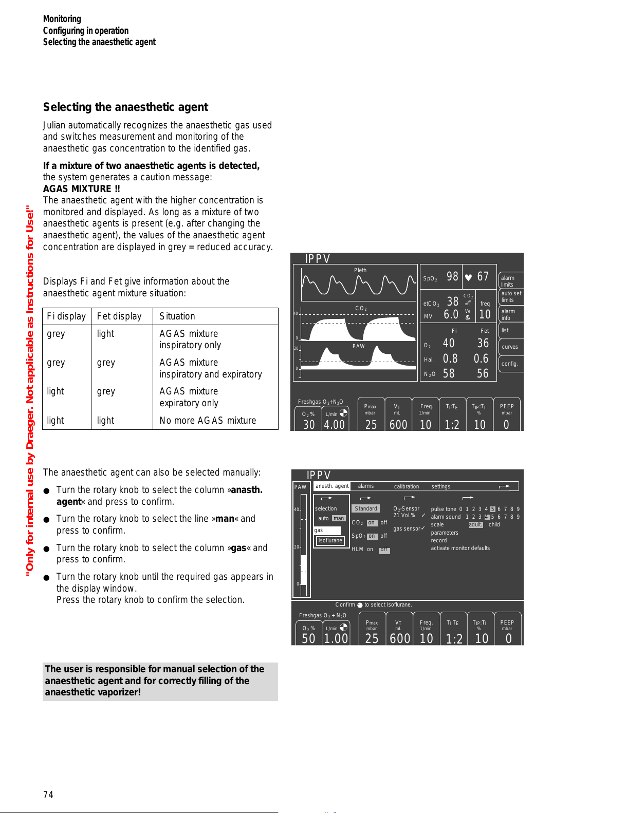
Selecting the anaesthetic agent
Julian automatically recognizes the anaesthetic gas used
and switches measurement and monitoring of the
anaesthetic gas concentration to the identified gas.
If a mixture of two anaesthetic agents is detected,
the system generates a caution message:
AGAS MIXTURE !!
The anaesthetic agent with the higher concentration is
monitored and displayed. As long as a mixture of two
anaesthetic agents is present (e.g. after changing the
anaesthetic agent), the values of the anaesthetic agent
concentration are displayed in grey = reduced accuracy.
Displays Fi and Fet give information about the
anaesthetic agent mixture situation:
Fi display Fet display Situation
grey light AGAS mixture
inspiratory only
grey grey AGAS mixture
inspiratory and expiratory
light grey AGAS mixture
expiratory only
light light No more AGAS mixture
The anaesthetic agent can also be selected manually:
● Turn the rotary knob to select the column »anasth.
agent« and press to confirm.
● Turn the rotary knob to select the line »man« and
press to confirm.
● Turn the rotary knob to select the column »gas« and
press to confirm.
● Turn the rotary knob until the required gas appears in
the display window.
Press the rotary knob to confirm the selection.
The user is responsible for manual selection of the
anaesthetic agent and for correctly filling of the
anaesthetic vaporizer!
74
Monitoring
Configuring in operation
Selecting the anaesthetic agent
Pleth
IPPV
alarm
limits
auto set
limits
alarm
info
list
curves
CO
2
40
0
PAW
0
20
config.
O
2
SpO
2
N2O
Hal.
40 36
0.8 0.6
58 56
Fi
Fet
etCO
2
38
98 67
6.0 10
MV
freq
600
V
T
mL
10
1:2
10 0
PEEP
mbar
Freq.
1/min
TI:TETIP:TI
%
25
Pmax
mbar
Freshgas O2+N2O
4.00
O
2
%
L/min
30
_
CO
2
Ve
O2-Sensor
21 Vol.%
gas sensor
IPPV
calibration
pulse tone
alarm sound
scale
parameters
record
activate monitor defaults
0 1 2 3 4 5 6 7 8 9
1 2 3 4 5 6 7 8 9
adult. child
alarms
600 10
1:2
10 0251.0050
settings
✓
✓
O
2
%
L/min
PEEP
mbar
Freq.
1/min
V
T
mL
TI:TETIP:T
I
%
Pmax
mbar
Freshgas O
2
+ N
2
O
selection
auto man
Standard
CO
2
on off
SpO
2
on off
HLM on off
Isoflurane
PAW
40
20
0
Confirm to select Isoflurane.
anesth. agent
gas
"Only for internal use by Draeger. Not applicable as Instructions for Use!"
All manuals and user guides at all-guides.com
Page 75

Manual calibration
Julian calibrates its sensors automatically during
operation. The message CAL appears instead of the
current measured value during a calibration process.
Calibration of the O2 sensor and zero calibration of the
other gas sensors can be repeated manually, for instance
if automatic calibration was unsuccessful.
● Turn the rotary knob to select the »calibration«
column and press to confirm.
● Select and confirm the appropriate line with the rotary
knob, for example:
»O2-Sensor
21 vol.%«
The calibration process is started when the selection is
confirmed. The clock symbol UUUU appears after the
relevant line, i.e. calibration is in progress.
When calibration is complete, a tick (✓) appears instead
of the clock symbol. A question mark (?) indicates that
calibration must be repeated because the previous
calibration was defective.
Other settings can already be made during the calibration
process.
O2-Sensor
21 Vol.%
gas sensor
IPPV
anesth. agent
calibration
pulse tone
alarm sound
scale
parameters
record
activate monitor defaults
0 1 2 3 4 5 6 7 8 9
1 2 3 4 5 6 7 8 9
adult child
alarms
600 10
1:2
10 0251.0050
settings
✓
✓
O
2
%
L/min
PEEP
mbar
Freq.
1/min
V
T
mL
TI:TETIP:T
I
%
Pmax
mbar
Freshgas O
2
+ N
2
O
selection
auto man
default
CO
2
on off
SpO
2
on off
HLM on off
Isoflurane
PAW
40
20
0
The anesthetic
agent is automati-
cally selected by
gas identification
75
Monitoring
Configuring in operation
Manual calibration
O2-sensor
21 Vol.%
gas sensor
IPPV
600 10
1:2
10 0251.0050
✓
O
2
%
L/min
PEEP
mbar
Freq.
1/min
V
T
mL
TI:TETIP:T
I
%
Pmax
mbar
Freshgas O
2
+ N
2
O
PAW
40
20
0
calibration
"Only for internal use by Draeger. Not applicable as Instructions for Use!"
All manuals and user guides at all-guides.com
Page 76

Monitoring
SpO2 Measurement
76
SpO2 Measurement (optional)
Sensor selection
Only use Nellcor sensors.
Note the Instructions for Use of the sensors –
incorrect positioning or use can cause tissue damage.
Select the sensor according to the following criteria:
– Patient weight
– Patient mobility
– Possible application site
– Patient perfusion
– Duration of use
The following table listing the specific sensor types
available and their characteristics is intended as an aid
for selection.
OXISENSOR I-20, OXISENSOR D-20,
DURASENSOR DS-100 A, OXISENSOR D-25 and
OXISENSOR R-15 are registered trademarks.
–––––––––––––
1)
in unopened, undamaged packaging
Sensor type OXISENSOR OXISENSOR DURASENSOR OXISENSOR OXISENSOR
I-20 D-20 DS-100 A D-25 R-15
Age group Infants Children Adults Adults Adults
Patient 1 to 20 kg 10 to 50 kg >40 kg >30 kg >50 kg
weight
Duration Short and long-term Short and long-term Short-term Short and long-term Short and long-term
of use monitoring monitoring monitoring zeitüberwachung monitoring
Patient Limited Limited Immobile Limited Immobile
mobility mobility mobility patients only mobility patients only
Preferred Toe Finger Finger Finger Nose
measuring site
Sterility
1)
Sterile packaging Sterile packaging ____ Sterile packaging Sterile packaging
"Only for internal use by Draeger. Not applicable as Instructions for Use!"
All manuals and user guides at all-guides.com
all-guides.com
Page 77

● Select the appropriate sensor.
On the back of the Julian:
1 Swing the flap over the socket »SpO2« to the left and
insert the sensor plug.
C-lock-ECG synchronization (optional)
If the patient is highly agitated or the arterial flow is very
low, the measurement signals of the SpO2 measurement
can be improved with the C-Lock-ECG synchronization.
In this case, Julian receives two separate signals that
transmit the heart activity:
– An optical signal from the SpO2 sensor
and
– An electrical signal from the separate ECG monitor.
Julian uses the R-wave of the ECG signal to identify the
pulse and to synchronize with the SpO2 measurement.
2 Channel the ECG signal of the ECG monitor with the
cable andyesck-plug to the back of the Julian
(»Sync.« socket).
See the "Technical data" on page 131 for the
requirements for the electrical signal and plug layout.
In the event of a delayed ECG signal
Synchronization may be impaired if the ECG signal is
delayed by more than 40 milliseconds to the QRS
complex.
If you suspect a fault of this kind:
● Use the Julian without C-Lock-ECG synchronization.
1
77
Monitoring
SpO2 Measurement
2
EKG
Monitor
"Only for internal use by Draeger. Not applicable as Instructions for Use!"
All manuals and user guides at all-guides.com
Page 78

Monitoring
SpO2 Measurement
78
Tips to prevent artefacts
Only use Nellcor sensors in the recommended positions,
otherwise incorrect measurements and tissue damage
may result.
Damaged sensors with exposed electrical contacts must
not be used – danger of electric shock.
Used adhesive strips of the Oxiband-OXI-A/N and
OXI-P/I sensor must not be reused, as they may not
adhere properly.
The strips must not be stretched unduly.
Never use two strips together, as this may lead to venous
pulsation and failure of the pulse signal.
High intrathoracic pressure, pressure on the thorax and
other consecutive impairments of the venous flow can
lead to venous pulsation with failure of the pulse signal.
The pulse signal may fail in the presence of shock, low
blood pressure, severe vasoconstriction, major anaemia,
hypothermia, arterial occlusion proximal to the sensor and
asystolia.
The sensor must be protected from exposure to bright
light (e.g. surgical lamps and direct sunlight), otherwise
the pulse signal may fail or inaccurate results may be
obtained.
The sensor should not be positioned on limbs together
with an arterial catheter, sphygmomanometer cuff or
intravascular venous infusion, otherwise the pulse signal
may fail and measurement become inaccurate.
Measurement accuracy may be reduced in the presence
of significant concentrations of dyshaemoglobins, such
as carboxyhaemoglobin or methaemoglobin.
Intravascular dyes, such as methylene blue, may also
impair measurement accuracy.
Electrocautery can impair the measuring accuracy; the
leads and sensor should therefore be positioned as far
away as possible from the electrocautery and its neutral
electrode.
Sensor performance may be impaired and lead to
inaccurate results if the patient moves violently. The
sensor should be applied to a different site in such cases
in order to reduce the risk of artefacts due to movement.
"Only for internal use by Draeger. Not applicable as Instructions for Use!"
All manuals and user guides at all-guides.com
Page 79

Applying the Durasensor DS-100 A
Reusable sensor for short-term monitoring of relatively
quiet patients weighing over 40 kg.
The sensor is preferably positioned on the index finger,
although other fingers can also be used. The little finger
should be used if the patient is particularly large or
obese.
● Open the clip slightly and slide the sensor onto the
finger. The tip of the finger must touch the end and
the soft padding should rest on the nail and tip of the
finger. The lead should be on top of the finger.
● Ensure that the finger is not compressed or hurt by
the clip.
● Change the application site after not more than
4 hours in order to avoid a build-up of blood pressure
(blocked circulation).
Follow the specific Instructions for Use when using other
Nellcor sensors!
79
Monitoring
SpO2 Measurement
"Only for internal use by Draeger. Not applicable as Instructions for Use!"
All manuals and user guides at all-guides.com
Page 80

Airway temperature measurement (optional)
Parts required:
– Temperature sensor 84 05 371
– Y-piece with connection
for temperature sensor M 30 543
– T-piece 86 00 224
– Filter 86 00 225
1 Connect Y-piece to respiratory hoses.
2 Insert T-piece into Y-piece.
3 Insert filter into T-piece.
4 Insert temperature sensor into Y-piece.
5 Connect temperature sensor plug to »Temp.« socket
at the back of the workstation.
● The airway temperature is displayed in the data
section of the screen:
AW temp. XX °C
The upper alarm limit is fixed. If the airway temperature
exceeds 40°C, the »AW Temp > !!!« alarm will be
activated.
80
Monitoring
Airway temperature measurement
4
3
2
1
5
"Only for internal use by Draeger. Not applicable as Instructions for Use!"
All manuals and user guides at all-guides.com
Page 81

Contents
Setting default values.............................................................................82
Setting the pulse tone...............................................................................83
Setting the alarm sound............................................................................83
Selecting the scale...................................................................................83
Setting the measuring parameters............................................................ 84
Record.....................................................................................................85
Time.........................................................................................................85
Configuring the interfaces........................................................................ 85
Interface...................................................................................................86
Setting default alarm limits........................................................................86
Setting default alarm limits for anaesthetic agents.....................................86
Adjustment range for default alarm limits...................................................87
Configuring curves...................................................................................88
Setting basic configurations......................................................................88
IPPV default settings................................................................................ 90
PCV default settings.................................................................................90
Setting the fresh gas default settings........................................................91
Manual calibration...................................................................................92
100 Vol.% O2 calibration..........................................................................92
O2 linearity test........................................................................................ 93
Selecting anaesthetic agent...................................................................93
81
Configuring in Standby Mode
Contents
Configuring in Standby Mode
"Only for internal use by Draeger. Not applicable as Instructions for Use!"
All manuals and user guides at all-guides.com
all-guides.com
Page 82

82
Configuring in Standby Mode
Setting default values
Configuring in Standby Mode
The default settings for the monitoring functions and the
fresh gas and ventilation parameters can be configured in
standby mode. The default settings for the monitoring
functions and the choice of anaesthetic gas are valid
whenever the apparatus is switched on. The default
values for the alarm limits, fresh gas parameters and
ventilation parameters are valid after each standby.
● Switch Julian to standby mode.
● Press the softkey »config.«.
Display (example):
The following settings can be made in the menu:
– Default settings
– Calibration
– Anaesth. agent
Fields highlighted by a grey background contain the
currently valid settings.
The symbol zzzzindicates a return to the previous
menu level.
● Select, set and confirm the new settings with the
rotary knob.
Setting default values
Default values are valid whenever the apparatus is
switched on. The default monitoring settings can be
activated during operation with activate monitor
defaults, see "Activating monitor defaults" on page 71.
● Select and confirm the default settings with the
rotary knob.
Display (example):
Standby / Configuration
anesth. agent
calibration
default settings
O2-sensor
21 vol.%
gas sensor
more
✓
✓
selection
auto man
pulse tone
alarm sound
scale
parameters
record
interfaces
alarm limits
curves
basic configurations
IPPV default settings
PCV default settings
fresh gas delivery
0 1 2 3 4 5 6 7 8 9
1 2 3 4 5 6 7 8 9
adult child
The anesthetic
agent is automati-
cally selected by
gas identification
Isoflurane
These default settings are password
protected.
The default settings are active
on start-up.
To change the default settings
enter the password:
0123456789
Turn and confirm .
Standby / Configuration
default settings
* * *
anesth. agent
calibration
O2-sensor
21 vol.%
gas sensor
more
✓
✓
selection
auto man
The anesthetic
agent is automati-
cally selected by
gas identification
Isoflurane
"Only for internal use by Draeger. Not applicable as Instructions for Use!"
All manuals and user guides at all-guides.com
Page 83

The menu requests the user to enter a 4-digit password
in order to prevent unauthorized tampering with the basic
settings. This password is notified during system training.
The function can be disabled by DrägerService if
required.
● Turn the rotary knob to select the digits con-secutively
from the line provided and press to confirm. The pass-
word is indicated underneath with asterisks (
* * * *
).
The menu for selecting the default settings appears
when the password has been entered correctly.
Display (example):
Setting the pulse tone (optional)
0 = OFF
9 = Maximum volume
● Select the line »pulse tone« by turning the rotary knob
and press to confirm. The cursor automatically jumps
to the last value selected (example 5).
● Set the value with the rotary knob and press to
confirm.
Setting the alarm sound
1 = Minimum volume
9 = Maximum volume
● Select the line »alarm sound« by turning the rotary
knob and press to confirm. The cursor automatically
jumps to the last value selected (example 4).
● Set the value with the rotary knob and press to
confirm.
Set a sufficiently loud alarm sound!
The audible »NO O2« and »NO FRESH GAS« alarms are
always sounded at maximum volume.
Julian complies with national regulations in certain
countries that stipulate a minimum volume of 45 dB (A).
Settings 1 to 4 are programmed at 45 dB (A) for these
countries.
Selecting the scale
To adapt the scale for the volumeter function and trend
curve.
● Select the line »scale« with the rotary knob and press
to confirm.
● Select »adult« or »child« with the rotary knob and
press to confirm.
83
Configuring in Standby Mode
Setting default values
Standby / Configuration
0 1 2 3 4 5 6 7 8 9
1 2 3 4 5 6 7 8 9
adult child
default settings
pulse tone
alarm sound
scale
parameters
record
interfaces
alarm limits
curves
basic configurations
IPPV default settings
PCV default settings
fresh gas delivery
anesth. agent
calibration
"Only for internal use by Draeger. Not applicable as Instructions for Use!"
All manuals and user guides at all-guides.com
Page 84
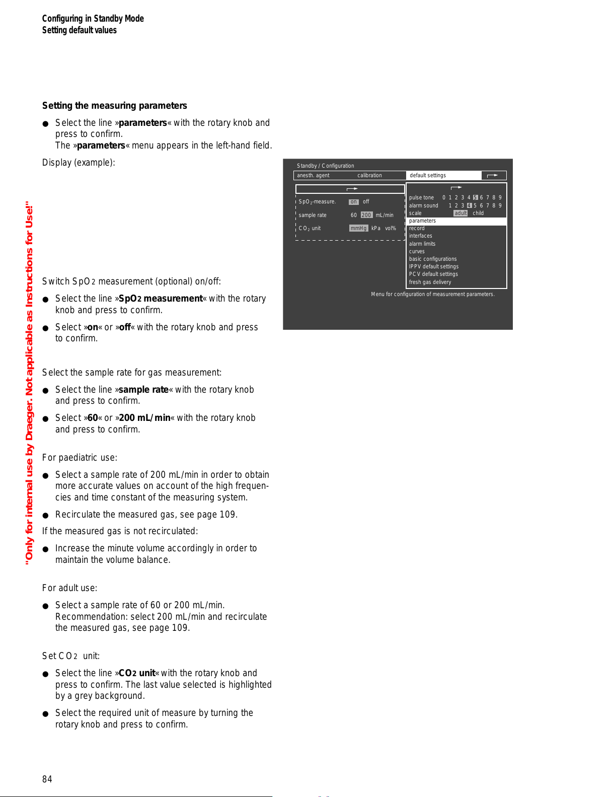
84
Configuring in Standby Mode
Setting default values
Setting the measuring parameters
● Select the line »parameters« with the rotary knob and
press to confirm.
The »parameters« menu appears in the left-hand field.
Display (example):
Switch SpO2 measurement (optional) on/off:
● Select the line »SpO2 measurement« with the rotary
knob and press to confirm.
● Select »on« or »off« with the rotary knob and press
to confirm.
Select the sample rate for gas measurement:
● Select the line »sample rate« with the rotary knob
and press to confirm.
● Select »60« or »200 mL/min« with the rotary knob
and press to confirm.
For paediatric use:
● Select a sample rate of 200 mL/min in order to obtain
more accurate values on account of the high frequen-
cies and time constant of the measuring system.
● Recirculate the measured gas, see page 109.
If the measured gas is not recirculated:
● Increase the minute volume accordingly in order to
maintain the volume balance.
For adult use:
● Select a sample rate of 60 or 200 mL/min.
Recommendation: select 200 mL/min and recirculate
the measured gas, see page 109.
Set CO2 unit:
● Select the line »CO2 unit« with the rotary knob and
press to confirm. The last value selected is highlighted
by a grey background.
● Select the required unit of measure by turning the
rotary knob and press to confirm.
Standby / Configuration
anesth. agent
calibration
0 1 2 3 4 5 6 7 8 9
1 2 3 4 5 6 7 8 9
adult child
SpO2-measure.
sample rate
CO
2
unit
on off
60 200 mL/min
mmHg kPa vol%
default settings
Menu for configuration of measurement parameters.
pulse tone
alarm sound
scale
parameters
record
interfaces
alarm limits
curves
basic configurations
IPPV default settings
PCV default settings
fresh gas delivery
"Only for internal use by Draeger. Not applicable as Instructions for Use!"
All manuals and user guides at all-guides.com
Page 85

85
Configuring in Standby Mode
Setting default values
Record
This function is used to determine the type of event that
triggers an entry in the record list or a printout on the
connected record printer.
● Select the line »record« with the rotary knob and
press to confirm.
The »record« menu appears on the left-hand side.
Display (example):
Time
interval-started (min)
A list entry is activated after a fixed time interval in
minutes.
NiBP-started
An entry is made after every NiBP measurement with new
measured values. This entry can be read by an external
Dräger monitor via the MEDIBUS interface.
Warning-started
An entry is made whenever an alarm is triggered.
Caution-started
An entry is made whenever a caution message is
triggered.
● Turn the rotary knob to select the event triggering the
entry and press to confirm.
Configuring the interfaces
Julian has three serial interfaces:
COM1, COM2, COM3.
COM2 and COM3 are configured as MEDIBUS*
interfaces and COM1 as printer interface. The interfaces
can be adapted to the connected equipment.
● Turn the rotary knob to select the line »interfaces«
and press to confirm.
The »interfaces« menu appears in the left-hand field.
Display (example):
COM2 is configured in the upper half of the menu and
COM1 and COM3 in the bottom half.
_____________
* MEDIBUS: Dräger communications protocol for medical equipment.
Standby / Configuration
anesth. agent
calibration
0 1 2 3 4 5 6 7 8 9
1 2 3 4 5 6 7 8 9
adult child
default settings
list entry:
time
intervall (min)
NiBP started
warning started
caution started
printer entry:
time
intervall (min)
NiBP started
warning started
caution started
12510 off
on off
on off
on
off
12510 off
on
off
on off
on
off
Menu for configuration of list and printer entries.
pulse tone
alarm sound
scale
parameters
record
interfaces
alarm limits
curves
basic configurations
IPPV default settings
PCV default settings
fresh gas delivery
Standby / Configuration
anesth. agent
calibration
0 1 2 3 4 5 6 7 8 9
1 2 3 4 5 6 7 8 9
adult child
default settings
Menu for configuration of Medibus and printer ports.
pulse tone
alarm sound
scale
parameters
record
interfaces
alarm limits
curves
basic configurations
IPPV default settings
PCV default settings
fresh gas delivery
COM 2 (Medibus):
baud rate
parity
data bits
stop bits
COM 1 (printer), COM 3 (Medibus):
config. of:
baude rate
parity
data bits
stop bits
1.2
9.6
even
8
1
COM 1 COM 3
1.2 2.4 4.8 9.6 19.2
even none
odd
7 8
1 2
"Only for internal use by Draeger. Not applicable as Instructions for Use!"
All manuals and user guides at all-guides.com
Page 86

Configuring in Standby Mode
Setting default values
86
Interface
Choice between configuration of COM2 or COM3.
Baud rate
Transmission speed (variable, see Instructions for Use of
the equipment to be connected).
Parity
This display is invariable for MEDIBUS and is shown only
for information.
Data bits
This display is invariable for MEDIBUS and is shown only
for information.
Stop bits
This display is invariable for MEDIBUS and is shown only
for information.
Setting default alarm limits
● Turn the rotary knob to select the line »alarm limits«
and press to confirm.
The »alarm limits« menu appears in the left-hand field.
Display (example):
● Select and confirm the required alarm limit with the
rotary knob.
The default alarm limit is highlighted against a white
background.
● Set and confirm the value with the rotary knob. The
value is then displayed in normal mode.
The cursor bar jumps to the next default alarm limit.
● Set the next default alarm limit as described above.
Setting default alarm limits for anaesthetic agents
● Turn the rotary knob to select the line
»anaesth. agent« and press to confirm.
The corresponding menu is displayed.
Standby / Configuration
anesth. agent
calibration
0 1 2 3 4 5 6 7 8 9
1 2 3 4 5 6 7 8 9
adult child
default settings
Menu for configuration of default alarm limits.
pulse tone
alarm sound
scale
parameters
record
interfaces
alarm limits
curves
basic configurations
IPPV default settings
PCV default settings
fresh gas delivery
--
95
40
30
120
50
3.0
--
--
20
40
8
SpO
2
etCO
2
MV
Fi O
2
PAW
anaesth. agent
"Only for internal use by Draeger. Not applicable as Instructions for Use!"
All manuals and user guides at all-guides.com
all-guides.com
Page 87

87
Configuring in Standby Mode
Setting default values
Adjustment range for default alarm limits
Fixed alarm limits / times:
FiCO2 Fixed upper alarm limit 5 mmHg
(deactivated in MAN/SPONT).
Apnoea pressure after 15 seconds
Apnoea flow after 15 seconds
Apnoea CO2 after 15 seconds
(after 60 seconds in MAN/SPONT)
– – : The default value set on delivery is outside the
monitoring range and the corresponding alarm limit
is therefore switched off.
The newly set default alarm limits are valid whenever
the apparatus is switched on or started up from
standby mode.
Certain alarm limits are switched off automatically in
MAN/SPONT ventilation mode and when using the
external fresh gas outlet:
see tables, alarm limits for MAN/SPONT, page 39
and alarm limits for non-rebreathing systems, page 51.
Alarm limit Adjustment range Default value
set on delivery
SpO
2
[%]
51 to 100
50 to 99
– –
92
Pulse
H
[1/min]
31 to 300
30 to 299
120
50
etCO2
[mmHg]
1 to 75
0 to 74
50 (mmHg)
– –
MV
[L/min]
0.1 to 39
0 to 38.9
12
3.0
FiO2
[Vol.%]
19 to 100
18 to 99
– –
20
Fi Hal.
[Vol.%]
0.1 to 7
0 to 6.9
1.5
– –
Fi Iso.
[Vol.%]
0.1 to 7
0 to 6.9
2.3
– –
Fi Enf.
[Vol.%]
0.1 to 7
0 to 6.9
3.4
– –
Fi Des.
[Vol.%]
0.1 to 21.9
0 to 21.8
12.0
– –
Fi Sev.
[Vol.%]
0.1 to 9.9
0 to 9.8
3.4
– –
PAW
[mbar]
5 to 98
0 to 35
40
8
_
_
_
_
_
_
_
_
_
_
_
"Only for internal use by Draeger. Not applicable as Instructions for Use!"
All manuals and user guides at all-guides.com
Page 88

Configuring in Standby Mode
Setting default values
88
Configuring curves
Three standard curves can be configured for each of the
ventilation modes: MAN/SPONT, IPPV, PCV and Fresh
gas external.
● Turn the rotary knob to select the line »curves« and
press to confirm.
The selection menu appears in the left-hand field.
Display (example):
● Select the required ventilation mode with the rotary
knob:
The »Standard IPPV screen« has been selected in the
example:
The currently selected parameters appear in the left-hand
field, followed by the selection menu with the curves
which can be selected.
● Select the required parameter in the selection menu
with the aid of the rotary knob and press to confirm.
The parameter appears against a white background.
● Select and confirm the position of the new parameter
with the rotary knob.
The corresponding position remains unused if »blank«
is selected.
Setting basic configurations
for time, date, language and tone sequence.
● Turn the rotary knob to select the line
»basic configurations« and press to confirm.
The selection menu appears in the left-hand field.
Display (example):
Standby / Configuration
anesth. agent
calibration
0 1 2 3 4 5 6 7 8 9
1 2 3 4 5 6 7 8 9
adult child
default settings
Screen configuration menu.
pulse tone
alarm sound
scale
parameters
record
interfaces
alarm limits
curves
basic configurations
IPPV default settings
PCV default settings
fresh gas delivery
default curves Man./Spont.
default curves IPPV
default curves PCV
default curves freshgas external
Standby / Configuration
anesth. agent
calibration
0 1 2 3 4 5 6 7 8 9
1 2 3 4 5 6 7 8 9
adult child
default settings
To select curve position: turn and confirm .
pulse tone
alarm sound
scale
parameters
record
interfaces
alarm limits
curves
basic configurations
IPPV default settings
PCV default settings
fresh gas delivery
CO2
PAW
Pleth
default curves IPPV
CO
2
PAW
Flow
Volumeter
Pleth
O
2
AGas
blank
Pressures
Standby / configuration
anesth. agent
Calibration
0 1 2 3 4 5 6 7 8 9
1 2 3 4 5 6 7 8 9
adult child
default settings
Menu for setting time, date, language and tone sequence.
pulse tone
alarm sound
scale
parameters
record
interfaces
alarm limits
curves
basic configurations
IPPV default settings
PCV default settings
fresh gas delivery
time
date
language
tone sequence
08 : 15
day month year
27 - 10 - 98
English (GB)
Dräger Euro-stand.
"Only for internal use by Draeger. Not applicable as Instructions for Use!"
All manuals and user guides at all-guides.com
Page 89

Setting the date/time:
● Select and confirm the »time« line with the rotary
knob.
The cursor bar marks the hours.
● Press the rotary knob to confirm and the value is
highlighted against a white background. It can now be
adjusted and confirmed with the rotary knob.
The minutes are adjusted and confirmed in the same
way.
● Set and confirm the date as described above.
Setting the language of the display texts:
The last language selected is highlighted by a grey
background.
The following alternatives can be selected:
English (GB) Swedish (SW)
French (F) Norwegian (N)
German (D) Portuguese (P)
Dutch (NL) Polish (PL)
Italian (I) English (USA)
Spanish (E) Japanese (Kanji) (JP)
Danish (DK)
To change the language setting:
● Turn the rotary knob to select the line »language« and
press to confirm.
● Select and confirm the relevant country code with the
rotary knob. The texts in the menu now appear in the
language selected.
Setting the tone sequence:
● Turn the rotary knob to select the line
»tone sequence« and press to confirm.
● Select and confirm either the Dräger alarm tone
sequence or the standard European alarm tone
sequence.
89
Configuring in Standby Mode
Setting default values
"Only for internal use by Draeger. Not applicable as Instructions for Use!"
All manuals and user guides at all-guides.com
Page 90

Configuring in Standby Mode
Setting default values
90
IPPV default settings
● Select and confirm the line »IPPV default settings«
with the rotary knob.
The softkeys for IPPV are displayed:
Display (example):
To modify the settings:
● Press the relevant softkey.
● Set and confirm with the rotary knob.
To return to the »default settings«:
● Press the rotary knob.
PCV default settings
● Select and confirm the line »PCV default settings«
with the rotary knob.
The softkeys for PCV are displayed:
Display (example):
To modify the settings*:
● Press the relevant softkey.
● Set and confirm with the rotary knob.
To return to the »default settings« menu:
● Press the rotary knob.
_____________
* Maximum setting for Pmax: 30 mbar.
Standby / Configuration
0 1 2 3 4 5 6 7 8 9
1 2 3 4 5 6 7 8 9
adult child
default settings
pulse tone
alarm sound
scale
parameters
record
interfaces
alarm limits
curves
basic configurations
IPPV default settings
PCV default settings
fresh gas delivery
Modify default settings or confirm .
600 12
1:2
10 025
PEEP
mbar
Freq.
1/min
V
T
mL
TI:TETIP:T
I
%
Pmax
mbar
anesth. agent
calibration
O2-sensor
21 vol.%
gas sensor
more
✓
✓
selection
auto man
The anesthetic
agent is automati-
cally selected by
gas identification
Isoflurane
Standby / Configuration
anesth. agent
calibration
0 1 2 3 4 5 6 7 8 9
1 2 3 4 5 6 7 8 9
adult child
default settings
pulse tone
alarm sound
scale
parameters
record
interfaces
alarm limits
curves
basic configurations
IPPV default settings
PCV default settings
fresh gas delivery
Modify default settings or confirm .
12
1:2
10 015
PEEP
mbar
freq.
1/min
TI:TEInsp. flow
L/min
Pmax
mbar
O2-sensor
21 vol.%
gas sensor
more
✓
✓
selection
auto man
The anesthetic
agent is automati-
cally selected by
gas identification
Isoflurane
"Only for internal use by Draeger. Not applicable as Instructions for Use!"
All manuals and user guides at all-guides.com
Page 91

Setting the fresh gas default settings
● Select and confirm the line
»fresh gas default settings« with the rotary knob.
The softkeys for the fresh gas settings are displayed:
Display (example):
To modify the settings:
1 Press the keys »N2O« or »Air« to select the default
carrier gas and press the rotary knob to confirm.
2 Press the softkey »O2 %«.
Set the default O2 concentration with the rotary knob
and press to confirm.
3 Press the softkey »L/min«.
Set and confirm the default fresh gas flow with the
rotary knob.
To return to the »fresh gas default settings« menu:
● Press the rotary knob.
91
Configuring in Standby Mode
Setting default values
Julian
1
23
Standby / Configuration
0 1 2 3 4 5 6 7 8 9
1 2 3 4 5 6 7 8 9
adult child
default settings
pulse tone
alarm sound
scale
parameters
record
interfaces
alarm limits
curves
basic configurations
IPPV default settings
PCV default settings
fresh gas delivery
Modify default settings or confirm ! Carrier gas selection via hardkey.
2.00100
O
2
%
L/min
Freshgas O
2
anesth. agent
calibration
O2-sensor
21 vol.%
gas sensor
more
✓
✓
selection
auto man
The anesthetic
agent is automati-
cally selected by
gas identification
Isoflurane
"Only for internal use by Draeger. Not applicable as Instructions for Use!"
All manuals and user guides at all-guides.com
all-guides.com
Page 92

Configuring in Standby Mode
Manual calibration
92
Manual calibration
Julian calibrates its sensors automatically during opera-
tion. The message CAL appears instead of the current
measured value during a calibration process.
Calibration of the O2 sensor and zero calibration of the
other gas sensors can be repeated manually, for instance
if automatic calibration was unsuccessful.
In standby / configuration mode:
● Turn the rotary knob to select the »calibration«
column and press to confirm.
● Select and confirm the appropriate line with the rotary
knob, for example:
»O2-sensor
21 vol.%«
The calibration process is started when the selection is
confirmed. The clock symbol Uappears after the relevant
line, i.e. calibration is in progress.
When calibration is complete, a tick (✓) appears instead
of the clock symbol. A question mark (?) indicates that
calibration must be repeated because the previous
calibration was defective.
To improve the measuring accuracy of high O2 concen-
trations, an additional 100 vol% O2 calibration and a
linearity test of the O2 sensor can be performed under
the menu option »more«.
Other settings can already be made during the calibration
process.
100 Vol.% O2 calibration
● Use a separate O2 source, e.g. O2 flowmeter.
O2 from the Julian breathing system is not suitable, as
it still contains traces of anaesthetic gas.
● Unscrew the sample line from the Y-piece and place it
in the continuous flow of the O2 source.
● Turn the rotary knob to select the line
»O2-sensor
100 vol.%«
and press to confirm.
● Allow the O2 flow to continue flowing into the sample
line.
A tick (✓) appears after the field when calibration is
complete.
● Screw the sample line back on to the Y-piece.
Standby / Configuration
anesth. agent
calibration
default settings
O2-sensor
21 vol.%
gas sensor
more
✓
✓
selection
auto man
pulse tone
alarm sound
scale
parameters
record
interfaces
alarm limits
curves
basic configurations
IPPV default settings
PCV default settings
fresh gas delivery
0 1 2 3 4 5 6 7 8 9
1 2 3 4 5 6 7 8 9
adult child
The anesthetic
agent is automati-
cally selected by
gas identification
Isoflurane
✓
✓
Standby / Configuration
O2-sensor
21 Vol.%
gas sensor
more
O2-sensor
100 Vol.%
linearity
test O
2
calibration
"Only for internal use by Draeger. Not applicable as Instructions for Use!"
All manuals and user guides at all-guides.com
Page 93

O2 linearity test
● First perform the "100 vol.% O2 calibration".
Then:
● Turn the rotary knob to select the line
»linearity
test O2«
and press to confirm.
After approx. 20 seconds:
● Display (example):
O2 21 vol.%
A display in the range between 18 and 24 vol.% is
correct.
If the display is outside this range, the O2 sensor is
defective or spent
(replace O2 sensor, see page 117).
Selecting anaesthetic agent
Julian automatically recognizes the anaesthetic agent
used and switches measurement and monitoring of the
anaesthetic agent concentration to the identified gas.
If »auto« is selected in the menu »anesth. agent«, the
anaesthetic agent is selected automatically.
The anaesthetic agent can also be selected manually:
● Turn the rotary knob to select the column
»anaesth. agent« and press to confirm.
Under the »selection« line:
● Turn the rotary knob to select »man« and press to
confirm.
● Turn the rotary knob to select the line »gas« and press
to confirm.
● Turn the rotary knob until the required gas appears in
the display window.
Press the rotary knob to confirm the selection.
● Check that the manually selected anaesthetic agent is
compatible with the Vapor unit.
The user is responsible for manual selection of the
anaesthetic agent and for correctly filling the
anaesthetic vaporizer!
93
Configuring in Standby Mode
Manual calibration
Selecting anaesthetic agent
Standby / Configuration
calibration
default settings
O2-sensor
21 vol.%
gas sensor
more
✓
✓
pulse tone
alarm sound
scale
parameters
record
interfaces
alarm limits
curves
basic configurations
IPPV default settings
PCV default settings
fresh gas delivery
0 1 2 3 4 5 6 7 8 9
1 2 3 4 5 6 7 8 9
adult child
selection
auto man
Isoflurane
Confirm to select Isoflurane.
gas
anesth. agent
✓
✓
Standby / Configuration
O2-sensor
21 Vol.%
gas sensor
more
O2-sensor
100 Vol.%
linearity
test O
2
calibration
First calibrate with 100 vol.% O
2
then expose sample-line to
to ambient air for about 2 minutes !
O
2
21 Vol. %
If the displayed value is outside
the range 18 to 24 vol.% O
2
the sensor is defective.
"Only for internal use by Draeger. Not applicable as Instructions for Use!"
All manuals and user guides at all-guides.com
Page 94

94
"Only for internal use by Draeger. Not applicable as Instructions for Use!"
All manuals and user guides at all-guides.com
Page 95
Contents
Dismantling components........................................................................96
Dismantling sample line............................................................................96
Removing water trap container................................................................. 96
Removing breathing hoses........................................................................96
Removing microbial filters.........................................................................97
Dismantling the suction system.................................................................98
Dismantling the breathing system..............................................................99
Removing the flow sensor.........................................................................99
Removing the absorber and bellows.........................................................99
Opening the breathing system................................................................100
Dismantle the anaesthetic gas scavenging system AGS..........................100
Removing waste gas connector..............................................................101
Dismantling emergency ventilation bag................................................... 101
Disinfecting / cleaning / sterilizing...................................................... 102
Breathing system................................................................................... 102
Surfaces................................................................................................ 102
Flow-Sensor.......................................................................................... 102
Microbial filter 654 St.............................................................................103
Care list for Julian anaesthetic workstation......................................... 104
Assembling...........................................................................................106
Installing the breathing system................................................................106
Inserting the flow sensor........................................................................ 106
Installing the bellows..............................................................................107
Filling and installing the absorber............................................................107
Installing the breathing hoses................................................................. 108
Preparing the suction system..................................................................108
Connecting the measured gas recirculation system................................ 109
Fitting waste gas connector....................................................................110
Sample gas scavenging..........................................................................110
Fitting emergency ventilation bag............................................................111
Connecting the anaesthetic gas scavenging system AGS.......................111
95
Care
Contents
Care
"Only for internal use by Draeger. Not applicable as Instructions for Use!"
All manuals and user guides at all-guides.com
Page 96

Care
Dismantling components
Dismantling sample line
● Unscrew the sample line from the Y-piece and water
trap on the back of the unit.
The sample line is not reusable and can be disposed
of with ordinary domestic waste.
Removing water trap container
● Pull the container of the water trap down and off, and
empty it.
Note the hygiene regulations of the hospital!
● Prepare the container of the water trap for disinfection
and cleaning in a washing machine.
When using the "Waterlock" water trap
● See separate Instructions for Use.
Removing breathing hoses
● Remove the breathing hoses and breathing bag.
● Dismantle Y-piece and connector.
● Prepare the breathing hoses, breathing bag and
Y-piece for disinfection and cleaning in a washing
machine.
96
Care
Dismantling components
"Only for internal use by Draeger. Not applicable as Instructions for Use!"
All manuals and user guides at all-guides.com
all-guides.com
Page 97

● Do not damage the breathing hoses!
Always hold the hoses by the connection sleeve and
not by the spiral ribbing when removing and
connecting the breathing hoses, otherwise the spiral
ribbing may be torn off the sleeve.
Breathing hoses with damaged spiral ribbing can
easily be kinked and interrupt ventilation!
Always check the breathing hoses for damage prior to
use.
Damaged breathing hoses must not be used.
Removing microbial filters
On the sleeve of the microbial filter:
● Press together the surfaces marked »PRESS« and
pull the filter off the connection at the same time.
Do not use force, otherwise the sleeve may be
damaged.
● Prepare the microbial filter for conditioning in
accordance with the separate Instructions for Use.
97
Care
Dismantling components
"Only for internal use by Draeger. Not applicable as Instructions for Use!"
All manuals and user guides at all-guides.com
Page 98

Dismantling the suction system
1 Remove the suction hose and vacuum hose.
2 Grip the silicone sleeve of the bottle cap and pull it
off.
3 Remove the secretion collecting bottle and flushing
bottle from the bracket and empty them.
Note the hygiene regulations of the hospital.
4 Remove the silicone sleeve from the lid of the
secretion collecting bottle.
5 Remove the overflow protection float from the rising
pipe.
Store the parts together for disinfection and cleaning
in a washing machine.
6 Replace the bacterial filter in the back panel of the
Julian – if soaked through or if contamination is
suspected.
The filter must be replaced at the latest every two
weeks.
● The bacterial filter must be disposed of as infectious
special waste. It can be incinerated with little pollution
at temperatures of more than 800 °C.
2
33
1
1
98
Care
Dismantling components
4
5
6
"Only for internal use by Draeger. Not applicable as Instructions for Use!"
All manuals and user guides at all-guides.com
Page 99

Dismantling the breathing system
7 Fold up the writing top.
8 Pull the catch and at the same time pull out the slot-in
module.
9 Hold breathing system by the handle and pull
upwards to remove.
Removing the flow sensor
1 Unscrew the expiration port.
2 Remove the flow sensor.
The flow sensor cannot be disinfected / cleaned in a
washing machine, nor can it be sterilized in high-
temperature steam.
● The flow sensor must be disinfected in 70 % ethanol
solution for approx. 1 hour.
Leave the sensor to dry in air for at least 30 minutes,
otherwise the remaining alcohol can damage the
sensor when calibrated.
● The flow sensor can be reused as long as it can be
calibrated successfully.
Removing the absorber and bellows
3 Turn the absorber counterclockwise and pull it
downwards.
● Empty the soda lime; it can be disposed of with
ordinary domestic waste.
4 Remove the insert from the absorber.
5 Turn the container of the bellows counterclockwise
and pull it downwards.
6 Remove the bellows.
● Prepare the absorber, container of the bellows and
the bellows for disinfection and cleaning in a washing
machine.
99
Care
Dismantling components
4
MAX
3
6
5
1
2
7
8
9
"Only for internal use by Draeger. Not applicable as Instructions for Use!"
All manuals and user guides at all-guides.com
Page 100

Opening the breathing system
– Weekly
1 Loosen the five sealing screws a quarter-turn with the
key supplied.
● Remove the cover.
2 Remove the two valve discs.
● Lift off the metal valve plate.
● Keep the valve discs in a cassette to protect them
against damage and prepare them for disinfection
and cleaning in a washing machine.
● Prepare the housing parts for disinfection and
cleaning in a washing machine.
Dismantle the anaesthetic gas scavenging system
AGS
3 Remove the scavenging hose.
4 Remove the transfer hose.
5 Remove the anaesthetic gas scavenging system.
● Prepare the individual parts for disinfection and
cleaning in a washing machine.
11
11
1
100
Care
Dismantling components
2
2
5
4
4
3
"Only for internal use by Draeger. Not applicable as Instructions for Use!"
All manuals and user guides at all-guides.com
 Loading...