

Page 1

9
5141.0
BA
'
Incubators
7010,
7310
OPERATING MANUAL
and 7510
Page 2

From
Drger:
Incubators
OPERATING INSTRUCTIONS
Important
For correct and
paratus,
point
1
2
4
and to avoid
out the
of the
use
Any
cise
knowledge
these
operating
The
apparatus
purposes
Manual or for
writing by Dragerwerk
The
apparatus
experts
cial
drawn
Only
at‘regular
report
up.
original Drager spare parts
Notice
effective
following:
apparatus requires pre-'
is intended
specified
purposes
should
of the
_
use of the
hazards,
and
observation
instructions.
in the
AG.
be
time intervals.
inspections
ap—
we would
the
for
only
Operating
confirmed
inspected by
An offi-
be
should
should
of
in
7010,
be used for maintenance and
Repairs
placement
carried out
We
repair
Customer Service
Branch or
Regular inspection
entering
Contract with the Technical Customer
Service of
Responsibility
the
operator
and
of
by experts.
recommend
work carried out
Agent.
into an
your
apparatus
in all
7310
maintenance,
spare
having inspections
Dr'ager
forthe reliable function
passes
cases
should
parts
the Technical
by
of
your
is best ensured
Inspection
Branch or
to the owner
where the
repairs.
and the
only
Drager
'
Service
and
Agent.
ap-
and
re-
be
by
of
or
paratus
or
the
been used
conform
7 For reasons of
ers
6
8 The
We would also
recommendations,
governing
should
7510
has been
repaired by
Drager Organisation
should be overhauled
years.
apparatus
in areas of
be observed.
persons
in
a
to the normal
explosive
point
the use of technical
DRAGERWERK
inexpertly
manner which
safety,
is not
out that the national
maintained
not
employed by
or where it has
conditions
pressure
at least
approved
risks.
regulations
equipment
AG LUBECK
does not
of use.
reduc—
every
use
for
and laws
Contents
Important
1
2
3 Construction ..................
3.1 to3.7 Standard
4
5
6
7 Care and Maintenance
8 OrderList
9 Scale
N
Notice .
........................
Duty
Technical Data
'
3.8
PreparatoryWork
Operation
Trouble
Shooting
Drawings
. . .' .............
................ 3
Accessory
. .« ..................
...r ................. 19
................
_
Equipment
Devices
..............
...............
.......... 16
Page
. . .
.,
...... 9
21
2
3
4
4
12
13
14
Fig.
Incubator 7010
1a
(with trolley
with base-unit
and
7011)
32(81b
Page 3

Fig.
.
1
Duty
1.1
Incubator 7010
The
Incubator
for
premature
Warmth,
concentration
provide
tory development.
Various
can
be added: for
for
aerosol
cation
of GNP
1.2
Incubator
The Incubator
construction as
its
large hinged
suited for
care
measures.
13
Intensive-care
'
The
Intensive-care
(Fig. Ic)
months old
lowing
surgery.
compared
larger
Plexiglass
removeable and
flaps)
surface,
surgical
1b
Incubator
is
lowered
7310
to
place
(with
trolley
the
baby
and with
inside
base—unit
(of. 3.5.2).
7011).
The
large
hinged
front
panel
38665»
intubation and
in
the
ple
7010
and
humidified
and
favourable
of
types
therapy,
and CPAP
7310
7310
the model
front
phototherapy
Incubator
is
designed
whose
Its
with
models
and
X-ray
procedures
ventilation
Intensive-care
(Fig. 1a)
sick
air,
protection
conditions for
is
raised
from
designed
oxygen
infection
satisfac-
newborn babies.
supplementary apparatus
of
ventilation.
7010.
it
is
7510
Incubator
secretions,
for
appli-
is of
similar
Owing
particularly
as intensive
7510
up
and fol—
aspiration
for
infusions,
(Fig. 1b)
panel
as well
for babies of
lives are at risk
mostimportantfeatures,
hood,
cassette
on
7010 and 731
hinged
swivelable
drawer.
children,
are all
Incubator
flaps
reclining
radiology,
quite
O,
(spring
Minor
sim-
7510.
to
to 6
are:
2
Technical
Scale
drawings:
Weights: (see
Noise level
Electrical
Alternating
Voltage:
100,
Current
Heat
Certifications
The
free in
Regulation
radio-protection
VDE: Verband
*)
(German
data
current
according
110, 127, 220,
consumption:
output:
apparatus
accordance with
0875,
Association of
Order
(inside):
250 W
marks
are
mark.
Deutscher
Data
see
page
List,
i
50/60 Hz
to order
240 V
300
interference
and
carry
21
page 19)
50
dB(A)
W
—
—
VDE*)
the
Elektrotechniker
Electricians)
f"
6”
Fig.
1 c
Intensive-care
Incubator
7510
cabinet and with
(with
base-unit
7011)
38816
Incubators with mark of
«Geprtifte
by
Technical
Sicherheit»
Inspection
conformity
(checked
Board Bavaria
safety)
Page 4
Construction
The
incubator mounted on
mobile
cabinet consists of the
housing
clining
glass
The air
ble to
cubator
and
tection from infection.
flows
ture
(and
electrical
air and the
by
sensors.
the
to
or
temperature
even. The ventilator also
with its electrical
surface for the
cover.
circulating
provide
temperature,
oxygen
then
concentration,
over the sensors of
regulator
and the
over the
heating forwarming
warning
the air
temperature
According
is
air
then
be
humidified,
wholly.
passed
The air
overthe
system
an
heating
devices are controlled
to the
or this is
circulation
base-unit,
baby,
makes it
adjustable,
the
desired
and
circulating
The
the
safety
element. The
measured
humidity setting,
over a
water surface
bypassed partly
reclining
continously
a
trolley
incubator
the re-
and a
Plexi-
possi-
even in—
humidity
good pro-
air fist
air-tempera-
thermostat
the incubator
by
the air
keeps
surface
draws
in ca. 25 l/min of fresh air from outside
through
with the
ded to the fresh air via a
or
is also
The
the
fect of
around the
carbon
3.1
Incubator base-units 7011/7012
These base-units contain all the electrical
operating
designed
They
tional
surement and
the
3.1.1
Switch
tor’
In
current-failure
very
switched off.
two bacterial filters and mixes this
circulating
air.
passed through
slight
positive
incubator
causing
dioxide
and control
as
differinthat base-unit 7012 has addi-
provision
pressure
by adding
air to flow out
and the
hood,
is thus
replaceable
for
skin-temperature
regulation.
’Disinfection in
the incubator
this
position:
position,
warning signal
the ventilator runs.
Only
Oxygen
flowmeter,
the bacterial filters.
fresh
flushed out.
equipment
can be ad-
and this
created inside
the ef-
air has
through
expired
baby’s
and are
plug-in
units.
mea-
leaks
Asep-
heating
remains
3.1.2 ,
Switch
ulation’
The
the desired incubator
between 28°C and
cubator
position: ’Air-temperature reg-
pointer
has warmed
regulator
temperature
deviations
of the incubator
ing
temperature
due to the tolerances
different
the
mometer and
ture
regulator.
the
gives
3.1.3
Skin-temperature
with
(only
The
baby‘s
means of a small
and
by
affixing
In
to
the switch
regulation’
tion’ the
on
played
atUre).
on the selector switch is set to
air
370. After the in-
automatically
at the desired
develop
may
set
thermometer and the
on the control knob. This is
of the
measuring
the sensor of the
incubator thermometer
The
definitive
base
skin
reading.
measurement
unit
7012)
temperature
temperature
the abdomen.
temperature
the
up,
proportional
maintains the
value.
between the reac-
apparatus
sites of the
tempera—
is measured
sensorfor
positions ’Air-temperature
and
’Skin—temperature regula-
gauge
skin
8
in
temperature
3
Fig.
(actual temper-
baby’s
Slight
and
ther-
is dis-
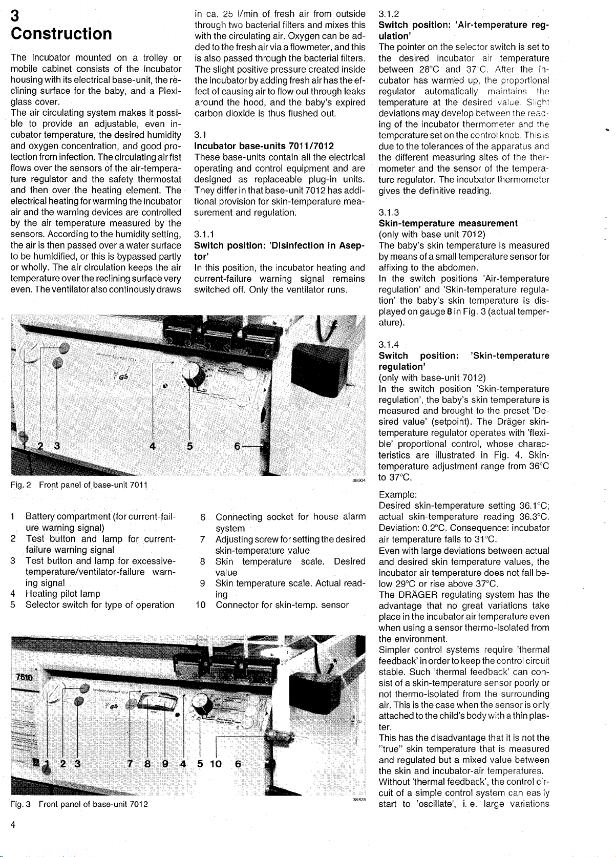
Fig.2Front panel
1
Battery
_
ure
2
3 Test button
warning
Test button
failure
of base-unit
compartment (forcurrent-fail-
signal)
and lamp for current-
warning signal
and
temperature/ventilator-failure
ing signal
Heating pilot lamp
Selector switch for
01-h
Fig.
Front
3
of base-unit 7012
panel
lamp
type
7011
'
for excessive-
warn-
of
operation
:
6
Connecting
system
7
Adjustingscrewforsettingthedesired
skin-temperature
8 Skin
value
Skin
9
ing
10 Connector for
socket
~
temperature
temperature
for house
value
scale. Desired
scale. Actual read-
skin-temp.
sensor
alarm
3.1.4
Switch
pasition: ’Skin-temperature
regulation’
with
(only
In the
base-unit
switch
regulation’,rthe baby's
measured
sired value’
and
(setpoint).
temperature regulator operates
ble’
proportional
teristics
are illustrated in
temperature adjustment range
to 37°C.
Example:
Desired
actual
Deviation: 02°C.
air
Even
and
incubator
low 29°C or rise above 37°C.
The DRAGER
advantage
place
when
the environment.
Simpler
feedback’
stable.
sist of a
not thermo-isolated
air. This is the case when
attached to the child’s
ter.
This has the
”true” skin
and
the skin and
Without
cuit of a
38 825
start to
skin-temperature setting
skin-temperature
temperature
with
large
desired
skin
air
temperature
that no
in the incubator air
a sensorthermo—isolated
using
control
in
order
Such ’thermal feedback’
skin-temperature
disadvantage
temperature
regulated
incubator-air
’thermal
simple
’oscillate’,
\
7012)
position
brought
’Skin—temperature
skin
to the
The
control,
whose
temperature
preset
Drager
with ’flexi-
charac-
4.
Fig.
from 36°C
skin-
Skin-
361°C;
reading
Consequence:
to 31°C.
falls
deviations between actual
temperature
does not fall be—
regulating system
great
temperature
systems require
to
the
keep
sensor
from the
the sensor is
body
that is measured
but a mixed value between
363°C.
incubator
values,
has the
variations
even
’thermal
control
circuit
can con-
poorly
surrounding
with a thin
that it is not the
plas-
temperatures.
control cir-
i.
system
e.
the
large
can
variations
easily
feedback‘,
control
is
’De-
the
take
from
or
only
4
Page 5
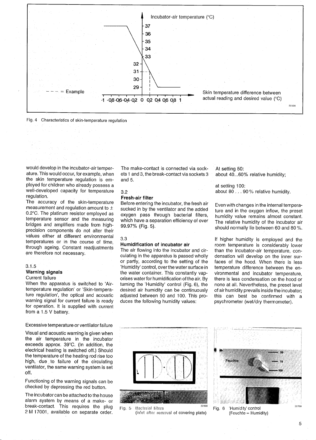
Fig.
4
— —
—
2
Example
Characteristics of
skin-temperature
-1
-0,8-0,6—0,4-QZ
regulation
37
36
35
34
33
0
Incubator-air
0,4
0,2
0,6
temperature (°C)
1
0,8
Skin
actual
temperature
reading
and
difference
desired
between
value
(°C)
would
develop
ature. This
the
ployed
skin
for children
would
temperature
well-developed
regulation.
The
accuracy
measurement
02°C.
The
platinum
temperature
bridges
precision
values either
and
components
temperatures
through
are
3.1.5
ageing.
therefore not
Warning signals
Current
When
temperature
failure
the
apparatus
regulation‘
tureregulation’,
warning
for
from a
signal
operation.
1.5 V
battery.
in
the
occur,
who
capacity
of the
and
regulation
sensor
amplifiers
at
different
or in
Constant
necessary.
the
for
current failure
It
is
supplied
incubator—air
for
example,
regulation
already possess
for
temperature
skin-temperature
amount
resistor
the
and
do
employed
the
made
not alter
environmental
course
readJUStments
is
switched to ’Air-
or
”Skin-tempera-
optical
and
with
temper—
when
is
em-
to i
measuring
from
high-
their
of
time,
acoustic
is
ready
current
The
ets1
and
a
3.2
Fresh-air
Before
sucked
as
oxygen pass
which have a
99.97%
3.3
Humidification
The air
culating
or
’Humidity‘
the
orises water for
turning
desired air
adjusted
duces
make-contact is
and3,the
5.
filter
entering
in
the
by
separation
(Fig. 5).
flowing
in the
apparatus
partly,
according
control,
water container.
the
’Humidity‘
humidity
between
the
following
connected via sock-
break—contact via
the
incubator,
ventilator and
through
bacterial
efficiency
of
incubator air
into
the
incubator and cir-
is
passed
to the
the water
This
constantly vap-
control
can be
setting
continuously
values:
over
humidification
50 and 100. This
humidity
sockets
the
fresh
the added
of over
wholly
surface
of the air.
(Fig. 6),
filters,
of the
the
pro-
3
air
in
By
this
At
about
at
setting
about
Even with
ture and
humidity
The relative
should
If
higher
room
than the
densation will
faces of
50:
setting
40...60%
100:
. .
80.
changes
in
value remains almost
normally
humidity
temperature
incubator-air
the
temperature
vironmental
there is less
none at all.
of
air
humidity prevails
can best
psychrometer
relative
90% relative
in the
the
oxygen
humidity
of the
lie between
is
employed
is
considerably
temperature,
develop
hood. When
difference
and
condensation on
on
incubator
Nevertheless,
inside the
be
confirmed with
(wet/dry
thermometer).
humidity;
humidity.
internal
inflow,
incubator air
60 and 80
the
there is
between
temperature,
the hood
the
preset
tempera—
the
preset
constant.
and the
lower
con-
sur-
inner
less
the en-
level
incubator;
%.
or
a
Excessive
Visual and
the air
exceeds
electrical
the
high,
ventilator,
off.
Functioning
checked
The
alarm
temperature
acoustic
temperature
approx.
heating
temperature
due
,to
the
by
incubator
system
same
of
the
depressing
can
break-contact.
2
M
17001,
available on
or
warningisgiven
in
39°C.
is
switched
of
the
heating
failure of
warning system
warning
the red
be
attached to
means of a
by
This
requires
ventilator failure
when
the
incubator
addition,
(In
the
separate
off.)
rod
signals
Should
rise too
circulating
is set
can be
button.
the
house
make-
the
order.
the
plug
or
5
Fig.
Bacterial filters
(inlet
.
after
F
.
removal of
32866
covering plate)
Fig.
6
’Humidity‘
control
(Feuchte=Humidity)
Page 6

3.4
Reclining
3.4.1
Reclining
7010 and 7310'
‘The
either
at
the
(head-up
Raising
position
side the
means of two metal
special request,
right
place
surfaces
surfaces of Incubators
under the
panel
end,
end-boards of the
or head—down
the
reclining
can also be undertaken
Plexiglass
mattress
as
desired,
hood. This is done
Fig.
of
the
reclining
for
down treatment and nurs-
laying
surface to the
supporting
8).
surface serves as a
ing equipment temporarily
the incubator.
can be raised
and
supported
reclining
surface
position) (Fig. 7).
sloping
from out-
levers
The shelf to
when
(on
the
working‘in
on
by
Fig.7Reclining
7310,
surface of
head-up
Incubator 701 0 and
position
82800
L
Fig.
:
8
Reclining
7310,
head-up position
porting
lever
surface
Incubator 7010
of
with metal
'
32808
and
sup—
9
Fig.
3.4.2
Reclining
swung
down
Reclining
cubator 7510
After
opening
reclining
either side as desired
drawn
minor
readily
move
head-
when the
(Fig.
lever
[surface
out
procedures
be
the child from the incubator. The
or foot-board can be folded down
or
9
has been
Head—up
The
reclining
separate
the
slope,
which the bed
lifted out
foot-board
position
child can
through
the
is done
grip
(Fig. 12).
one of the hand
reclining
in much
is
slightly
releasing
surface.
The Intensive-care
available on
reclining
surface described
surfaCe‘of Incubator 7510
out on
left,
surface of Intensive-care
the
large
can be
incubator
(Figs.
parallel
performed
reclining
10)
or
steps
window is
by
until it
be
button,
(Fig.
such as intubation
without
surface is
the relevant
after
pressed
head-down
bed can be raised
at each end. To
downwards.
position
opened
is to be raised. The bed is
the
hand-grip
engages
At
the same
held with the
firmly
surface to the normal
the same
while
raised
lowers the
which
Incubator 7510 is also
order with the
special
head-board folded
flap,
9 and
In this
having
out on
10)
way,
to re-
swung
11).
hinged
supporting
in
three
adjust
at that end at
of the head- or
in
the desired
time,
free
hand,
ports. Lowering
position
The
way.
upright
depressing
reclining
simpler
3.4.1.
in
32304::
In-
the
or
can
out
the
the
the
Fig.
Fig.
10
12
Reclining
swung
down
Reclining
out on
“wan
surface
right,
surface
of Incubator 7510
foot-board
of Incubator
turned
“'
L
lmensivpagoxkubmor
7510
m;
Fig.
i
X
head-up position
11
7510
Reclining
drawn out
’
£
surface
parallel
‘
Incubator 7510
of
32796
WWI
32 787 a
6
Page 7

X-rays
Beneath
on
which
drawer in
from
placed
Before
necessary
3.5
Plexiglass
the
X-ray permeable
the
baby’s
which
outside
to
hoods
out
open
pulling
an
mattress
X-ray
the
the
a small
incubator
drawer,
plastic
panel
there
lies,
cassette can be
is a
(Fig. 13).
it
is
only
in
the hood.
flap
Fig.
13
Reclining
X-ray
surface of lncubator
drawer
7510
3.5.2
Plexiglass
hood of
(Fig. 1b)
to
Contrary
sion is fitted with
which can
facilitates a
sures
remain within
tective
can also be
taken out
the model
be
during
hood need
through
opened
number of
which
the
placed
Even‘photo-therapy'
since
pushed
the
asidewhenthe
rupted
not
is
opened.
be
Incubator:
7010 the
a
large hinged
(cf.
Fig. 1b).
therapeutic
the little
incubator and the
not be lifted.
into the
this
incubator and
hinged panel.
must not be
photo-therapy
hinged panel
'
7310
7310 ver—
front
patient
The child
unit
panel
This
mea-
may
pro-
inter—
must
3.5.1
Plexiglass
(Fig.
1a)
Four
iris-diaphragm
the
usual
Hinged
ted to
special
phragms
Used
washing
removed
caily
at
each end.
of
each of
windows
ing
hoses,
large
apertures
smaller
hood
access
flaps
(see
A
the
provide
hoses
of
Incubator 7010
hand
and
nursing
(spring flaps)
order in
place
Fig. 14).
can
be
simply
through
largish
openings
permits
e.g.
and
the
aperture
covered
the
ventilator
for.
cables.
ports
can also
of
and
sliding
suspension
hoses.
the
provide
measures.
be fit-
the iris dia-
hygieni-
windows
to one
the
by
Further
passage
side
slid-
for
3.5.3
Plexiglass
cubator 7510
In
the front of the
also a
large hinged panel
lowered to
out of
the incubator
(see
3.4.2).
should be
panel
opening
and its
hood of
(Fig.
the
lay
It
is vital
Intensive-care In-
1C)
Plexiglass
which can
inside or
baby
on the
reclining
that the
properly
fastenings
hood
there is
to
pull
surface
large
hinged
closed after
securely
be
it
en—
gaged.
of
of
t
A smaller
the
Four
hinged flaps
32806a
Fig.
14
Opening
the
hinged flaps
(spring flaps)
and
open silently
the
can
lris-diaphragms
cial
Ventilation hoses can
sliding
thus led to
The rod can be
of
the
tures in the
small
hinged
drawer
X-ray
large
hand
provide
nursing
measures. The
with
releasing
also be closed
in
order,
rod
beneath the
the
as
hood,
hood
hoses and
place
panel provides
(see Fig. 13).
ports
for the
light
mechanism
again
can
also be fitted to
of
be
from above
baby
fitted on
desired.
provide
of cables.
equipped
usual
elbow
(Fig.
with
the
spring flaps.
suspended
of the hood and
top
the
right
Numerous
for the
flaps spring
pressure
14). They
the elbow.
or left
passage
entry
with
access
on
spe-
from a
(Fig. 15).
side
aper—
to
of
Fig.
3.5.4
Double wall
Function of the
A
second wall inside the incubator
possible
radiation
incubator. The air which
heating system
between outer and
inner wall
which
erature within the
ble walls the
surfaces of the hood
than the air
The child
side
walls and
radiation
15
incubator
7510 with
ventilator
Babylog
1 and ventilator
hoses
entering
incubator
41 354
particularly important
system
to reduce the
heat to
is warmed
almost
corresponds
average temperature
(Fig.
double wall
the inner surface of the
of the incubator also
innerwalls
up
incubator. Without dou-
is
temperature
is surrounded with warm
undercooling
heat is thus
for
15a)
system
child’s loss
is warmed
whereby
to a
temperature
to the air
roughly
in
the incubator.
due to loss of
prevented.
premature
makes it
by
flows
temp-
at inner
3°C cooler
top
This is
infants
of
the
the
and
7
Page 8

of less than 1500
losses of heat
tion have to be
the air
temperature
relative
humidity
g body weight.
convection and
by
compensated
and/or
in
the
incubator.
Description
The
all incubator hoods of
and 751
tion.
The
model
glas
walls
hood.
with
wall
shaped
which
AcCess't'o
of the incubator
double wall
also
place.
Assembly
walls can
rapidly.
mounted to the
through
are secured from
nuts.
wall
double
0,
additional inner wall for the incubator
7010
pane,
and
In
the
even
which
the
case
large
syStem
for
consists
upper part
of
hinged
system comprises
and
one
‘is‘attached
the
child
hood is
system,
have
large
and
be carried out both
Threaded
bores in the incubator hood and
‘
can be
models
supplementary
of a
U-shaped
in
runs
parallel
of
models
7310
front
two
plane pane,
the
to
large
thrbugh
not
since the inner walls
openings
disassembly
which are
pins
inner walls
outside
by way
Further
evapora-
by increasing
increasing
supplied
7010,
installa-
to the
the incubator
and
the inner
panel
—
parts
the latter
hinged flap.
the
handports
impairedby
at the same
of the inner
easily
are
pushed
of knurled
7310
Plexi-
side
7510
one
and
firmly
the
for
L-
of
the
[supplementary
The
incubator hood must be
bores for
double wall
performed
Agency.
-
3.6
Rails
For
supporting
plementary
each end of the
System”).
3.7
Trolley
The
place
The
mm
The
7310 are
7510;
of these
sated for.
(see
great
accessories
two self-
diam.)
trolley legs
in this
installation
supplementary
system.
by
your
various
apparatus
incubator
_
Figs.
floor of the
-steering
can be
of Incubators 7010
than those
longer
the different
way
of
types
apparatus
provided
installation
This Work is best
Drager
Branch or
types
there is a rail et
(“Drager
1a and
locked.
1b)
trolley
'
front wheels
can be used
of Incubator
hood
are
of the
of
heights
compen-
with
sup-
Rail
(100
and
to
16 incubator cabinet
Fig.
with
open
door
Page 9

3.8
Accessory
(on
special
3.8.1
Cabinet
The
with
The
means of
Each door
treatment
paratus
cabinet.
The
7310-are
7510;
of
sated for.
(see
mobile cabinet
doors on
doors can
can be
cabinet
in
this
these
types
Devices
order)
Figs.
the front
be
pressure
contains a
material
placed
legs
than
longer
the
way
of
_
1c and
opened
16)
is a
trolley equipped
and
and
with
(e.g.
large storage
(Fig. 16).
on
the floor of the
of
Incubators 7010
those of
different hood
apparatus
back.
closed
the
Larger ap-
incubator
are
compen-
knee).
tray
and
heights
by
for
3.8.2
02-dosage
The
ment
(Fig. 17)
oxygen required
of the
incubator
incubator via a
a
ter,
connecting
The
tached
clamp
oxygen
dosage
valve
to
the
(Fig. 17).
is
not
humidification takes
3.8.3
Oxygen
An
cubator. The
below
necting
.Two
the
a)
b)
3.8.4
Oxygen
So
high
.
acute
ployed.
via a
meter
hose.
If
the
limiter
oxygen
even with
open,
can flow
ponds
40%.
if
the
of
no
as to
limiter
flowmeter in
O2
the
nozzle
switch
a lower
positions
position:
more than
no
into the
to an
manual control of
White
dosage
less
than 6 l/min.
Red
position:
limitation of
helmet
administer
concentration
asphyxia,
The
oxygen
humidification
(setting
a
very
high
neck
baby’s
nappy-
,
for
air is
nozzle
with
valve with
and a
flowmeter are
rail
dosage
incubator
Humidifications of
necessary,
in
place
(Fig. 18)
can be
attached to the
oxygen
limiter
place
(3.8.2).
can be
the limiter:
the
02-dosage
6 l/min of
incubator. This
oxygen
concentration of
Oz-conCentration
valve is
O2
adjusted
‘
inflow.
(Fig. 19)
oxygen
as
rapidly
a
Plexiglass
is fed into
nebuliser with
10
02
should be
and a
l/min)
concentration is
sealed off with
oxygen-enrich-
passed
into
glowme-
rubber
hose.
means of
by
as
optimal
the
incubator.
is screwed on
of
the con-
engaged
valve
oxygen
corres—
_
is
desired,
to an
inflow
to the
baby
as
possible
helmet is em-
the helmet
Oz-tlow
corrugated
desired,
the
at-
the
in-
on
fully
ca.
in
in
M
17
flowmeter on
Fig.
a
O2
incubator rail
270
.3
208
18
Fig.
a
Fig.
Ozflowmeterwit
19
Oz
helmet
h
limiter
02
39
39 209
t
20 Water nebuliser
Fig.
3.8.5
Water
nebuliser
it is
possible
the incubator. With
water nebuliser is
cubator at one
surface
clining
led in
through
nebuliser with the outlet
compressed-air supply.
tioned
parts
The water nebuliser is
Prospectus
In
the
incubator,
powered onlybycompressed
ing oxygen
high oxygen
When the water
compressed
the
oxygen
cannot be utilised.
output (aerosol
varied with the
the
purpose (setting
aerosol;
The
nebuliser is also
setting
quantity
ing pressure.
constantly
compressed
ter nebuliser will
mixing
given
tion in the
no
oxygen
more
in
oxygen
necessary,
is
ratio between
in the table
longer
concentration
oxygen
the table. Should
be
attached,
(Fig. 20)
to
carry
out
the aid of
suspended
of the
end-boards of the re—
(Fig. 20).
an
opening
are available
described
6224e
(older
the nebuliser
to
concentration in
air,
concentration on
power
nebuliser is
the
provision
it would
However,
quantity per hour)
control knob
40%
02:
of
aerosol
dependent
in
addition to
drawn in
air
by
required
enter the
’Oxygen
incubator‘
applies.
must
required
if
an
to set it to the
(page 13)
To obtain a
be fed in than
more than
for
oxygen
aerosol
valve of the central
the
for
in
this
limiter
therapy
a
holder,
in
A
pressure
in the
hood,
The aforemen-
on
special
in
no.
8424e).
should be
since us—
air,
produce
the incubator.
powered by
for
adjusting
the nebuliser
the nebuliser
designed
100%
02:
much
aerosol).
delivered
on
the
the fresh air
ventilator,
driving
incubator. The
air
and
oxygen
concentra-
therefore
the
incubator,
is shown
6 l/min of
purpose,
(see
red
position.
32 811
in-
the
hose,
links
order.
detail in
can be
for
little
the
by
operat-
the
the wa-
desired
it
3.8.3)
in
a
a
is
Page 10

Nebulisation of
These substances should be
in the incubator with
when
only
clearly
dangers
_
taken into account that
stances
es of the
override the
predispose
reduce the
thorough
is
absolutely
3.8.6
Medication
Medicaments
incubator.
medication
holder
special
front of
the
large part
be
directly
purpose
that
will
be
apparatus,
strongly
risk of
routine
essential.
nebuliser
instead
nebuliser
baby’s
ofthe
inhaled.
are
available on
expectorants
the water nebuliser
the
anticipated
disadvantages
be involved. it must be
may
deposited
and the residues
to
fungal growth.
infecting
cleaning
of
(Fig.
can also be
of the
(Fig. 21),
face in such
nebulised
All
nebulised in
water
is
employed.
it can
medicament
parts
required
special
applied
benefits
these sub-
on all
surfac-
the
the incubator
21)
nebuliser,
With a
be
placed
a
way
forthe
order.
and
baby,
the
that
can
To
a
in
a
3.8.8
Infusion
The
infusion stand is
and can be
screw
clamp.
22
Fig.
Oxygen
.
stand
fixed to the
(Fig. 24)
adjustable
incubator rail with a
distributor
in
height
3.8.9
Small
operating-theatre
For
diagnosis
the
baby,
offers
a well-defined
colour-corrected
cold,
secured to
be ordered
and
swivelled so as to
the incubator.
Replacement
cated on the external
lamp
body.
screwdriver. The
withdrawn. The bulb is
be taken out
may
and
turning
reassembling
to the
paid
behind the chrome
lying
element must lie
disc. The filter
into the
Technical data:
Mains
Current
illumination
and for
the
small
operating-theatre
an incubator rail with a
separately.
of bulbs:
These are
complete
by
to the left
the
lamp,
following:
up against
element can be
lamp body
supply:
in
220 V
consumption:
intensity:
lamp (Fig. 25)
minor
procedures
lamp
concentrated field of
The
light.
lamp
clamp
it can be
illuminate
two screws are lo-
circumference
unscrewed with a
filter
now accessible
pressing
rotated
any part
of the
element is
and
backwards
(bayonet fitting).
attention
the round rUbber
only
50 W
ca.
of the filter
ring
the
introduced
one
3000 Lux
should be
ring
Plexiglass
position.
on
is
to
of
in
21
Fig.
3.8.7
Oxygen
The
plug-in
Medication nebuliser
distributor
oxygen
distributor contains
sockets,
utilising pieces
tached
apparatus,
inhalation
tributor is
Two different
able for selection:
at
the same time
secretion
apparatus).
suspended
a) Oxygen
connector
valve ofacentral
b) Oxygen
nector,
gauge
gen
ment to a
sible.
distributor with
pressure
(for
cylinder
central
so that several
of
apparatus
oxygen
distributor
(for
supply
connection
B
2533).
22,
(Figs.
aspiration
on an
distributors are avail-
(e.g.
The
oxygen
incubator rail.
23)
3
oxygen
oxygen-
can
be
ventilation
apparatus,
without cylinder
the wall
from
Oz
installation).
cylinder
reducer
02installation
to a
Here
and
3-litre
too,
pressure
attach-
is
dis-
con-
oxy-
pos—
at—
Fig.
Fig.
23
Oxygen
nector
24 infusion
distributor
stand
with
cylinder
con-
35494
Fig.
Fig.
25 Small
26
Distribution
operating-theatre
box
lamp
32 818 a
35
496
10
Page 11

3.8.10
Distribution box
A
distribution
sockets can
cubator
taneously
apparatus
sion
surplus
cables can
distribution
pump,
rail. It
with
(e.g.
monitoring
length
be
box.
box
be
can
various
incubator
of
placed
26)
(Fig.
equipped
suspended
be
types
apparatus
the
various
in
with
6
safety
from
the in-
connected simul-
of
electrical
etc.).
infu-
The
base-unit,
connecting
the
pocket
of
the
_
-
_
“
;
9heto»Tnerame
3.8.11
Phototherapy
(Prospectus
irradiation of
The
babies with
the aim
serum
bilirubin
a
critical rise. in
ing
transfusion
3.8.12
Bronchial
(Fig.
28)
The
apparatus
mounted
ejector
produces
pressure.
the
baby's
catheter.
sucking
rinsing
The
the
fluid.
apparatus
compressed
Cf.
appropriate
‘
apparatus
6141
.31e)
newborn
from
mild
thus
be
suspended
incubator.
an
this
the
equipment
adjustable
light
of
lowering
concentration
can
aspiration
on
the
is
Secretions can be
airways
The
catheter
by
rinsing glass provides
through
is
powered
air.
Operating
(Fig. 27)
and
premature
apparatus
already-raised
orof
prevent-
cases,
avoided.
exchange
from
The
negative
removed from
means of a
with
water
with
oxygen
Manual.
has
the rail
integral
thin
for
if
“ImenwvnW-amkumtor
5
i
or
or
15w
.
.1
3a8cuim
The
foam
inside,
comes
put
fixed
tions of
after
resia),
entire
be
instance,
Evacuation
degree
out with
the
tion
After
been
hose
mattress
vacuum
balls.
into
after
After
the
normally
’stiff‘. It
particular
evacuation.
the
baby,
mattress is
operations
can
be
attained in
baby,
orjust
comfortably positioned
for
infusions
of the
of
hardness is
suction
mattress
(turn
the
hose
desired
obtained,
coupling
has to
coupling
to
(Fig. 29)
extraction of
flexible
can
previously
positions,
Thus
such
for
(e.g.
the
arms and
or
mattress to
most
equipment.
be
opened
degree
the
valve is
the
right).
filled
with
the air
mattress
have
which
extreme
as
those
oesophageal
ideal
fashion.
legs,
as
desired,
taking
X-rays.
the
simply
The
for
to
the
left).
of
”hardness” has
closed
small
from
be—
been
remain
posi-
required
The
can
desired
carried
valve of
evacua-
(turn
at-
for
E
27
'23
incubator
Bronchial
Fig.
’
7
Fig.
with
phototherapy
aspiration equipment
apparatus
32819;!»
Fig.
29 Vacuum
~-
mattress
11
Page 12

Fig.
31
Baby
scale
32 8l5
33 Instrument
Fig.
tray
336073
3.8.14
Securing straps (Fig. 30)
The side walls of
sive-care
can be used to secure
securing straps
which are well suited
sures,
arms and
baby's
separate
order.
incubator
the mattress of
possess
the
2
M
13898
can be
legs,
4
Preparatory
4.1
Unpacking
When the
packing
from inside the
tates removal of the brown
and
apparatus
material
Work
setting up
is
must also be removed
apparatus.
the inten-
slots which
Padded
baby.
with
velcro clo-
to
securing
supplied
unpacked,
This necessi~
covering plate.
3.8.15
scale
Baby
The scales are
are
the
on
They
fore be used
cubators in the
baby
suspended
The
the
The scales are
with the
EO)
easily
is
laid
baby‘s weight
sliding weights.
German standard
and
approved
Germany.
amounts to 7.5
4.2
Cleaning,
Cleaning,
ing
in section 7 Care and Maintenance.
tasks should also be carried out before
the
tial
.
Before
that the mains
the indicator
disinfection,
readiness for use
commissioning.
connecting
31)
(Fig.
placed
removable and can there—
in
turn for all the DRAGER in-
ward. For
in
a
weighing
from the hook on the scales.
is determined
calibrated
for use as
The measurement
kg.
functional
are
the
voltage corresponds
on the incubator.
plate
on
top
weighing,
sheet which is
in
(Eichordnung
baby
testing
assembly
described
apparatus,
of the hood.
by moving
accordance
scales in
range
test run
and
and
in
detail
These
check
the
test-
ini-
with
—
3.8.16
Instrument
The
stainless
cubator
cm.
20
rail,
tray (Fig.
steel
measures:
tray,
33)
secured to
width
30
cm,
the
depth
in-
”my.
in)
llillll
1
Mounting
Place hood onto incubator and
pins (at
incubator
Now unscrew the screws of the lower-
the
the
housing).
Plexiglass
hood)
hood:
into the lower
press hinge
hinges (at
hinge parts, place securing plates (which
are
comprised separately)
hinge parts,
34).
Fig.
Mounting
panel (at
hinges
described above.
Securing
cords at each end are to be
ing
the hood.
12
and attach screws
the
large hinged Plexiglass
Incubators 7310 and
are mounted in the same manner as
the
Plexiglass
over the
hood: The retain-
again
7510):
clipped
lower
(of.
front
The
onto
4.3
Humidification
Fill
the water container with distilled
the water indicator
pulling
the
purpose (Fig. 35).
The water
tained
between the two lines marked max
and min.
To
prevent
silver
compound
water at each
use
4
of
Micropurtablets
quid
Micropur
Katadyn-Gesellschaft
straBe
20,
Micropurtablets
led water before
of incubator
level should
bacterial
growth
should be added
refilling.
We recommend
(manufacted
D—8000 Mtinchen
mbH,
must be dissolved
beingvadded
MBT 1 orl cm3
glass
always
in
air
water,
forward for
be main-
the
water,
to the
Deutsche'
by
Schaufelen—
12).
in
distil-
to the water.
The
the
34 Screw
Fig.
a
li-
35
Fig.
hinges including
plates firmly
the water container
Filling
to
incubator
the
‘m
securing
32794
Page 13

(Note:
Silver
added to
nebulisers.)
Set
the
control
4.4
desired
lever
,
Heating-up
Set the
desired
the
selector switch
ation’
lamp
The incubator
after
a heating-up period
This
level is
blinks
lamp
=
desired
Check
value).
the
temperature
compounds
the
water
humidity
(Fig. 6).
the
Incubator
incubator
(’air~temperature
comes
on).
temperature
then held
periodocally
temperature
gange.
may
supply
on
the
temperature
set is
of
ca.
constant
when
on
theincubator
not be
of aerosol
’Humidity‘
with
regul-
reached
30...60 min.
(‘heating’
actual value
After
the other end
been introduced
its
hood,
contains the
be
and
tant to see that
wet,
otherwise
ing).
slightly
temperature
secured between
sternum with
the
as false
This
skin-temperature reading
result
danger
ings by evaporation
if
one of the
over the
with
securely
a further
isolating
plaster (3)
l
of the
sensor
cable
thickened
an
aperture
tip
(1),
through
element,
the
plaster
plaster
to
(due
of
evaporation
falsification of the read—
cooling
caps (2)
fixed
temperature
umbilicus
baby’s
It is
(3).
has
not become
can be averted
is stuck down
(Fig. 36).
has
in the
which
should
impor-
cool-
sensor
value,
cubator
tion of
sired
value. In
incubator-air
29°C or
deviations
will
Experience
baby’s
rapidly,
handled,
ing
Although
cubator
bance
cubator-airtemperature,
for the
brought
Deviations of
between the
actual skin
therefore
regarded
in that
air
temperature
the skin
doing
temperature
rise
above
from
in
skin
temperature
e.
when
g.
going
the
regulation
reponds
by raising
baby‘s
back
to the
about
preset
temperature
develop
as
normal.
it
raises or
temperature
so,
37°C even
the
desired value.
practice
the
babyisfeeding,
to
sleep
immediately
or
skin
temperature
desired value
one-tenth of a
desired
at
any
lowers
to
counter
from the
it will
not
to fall
shows that
often
and
waking
system
to
any
lowering
it takes
value
indicated can
time and
the in-
devia-
allow the
below
with
large
changes
of the in-
distur-
the in-
sometime
to be
again.
degree
and the
are to be
de-
the
be-
etc.
5
Operation
5.1
Incubator
(see
the
Lay
ed-up
baby’s
periodically;
air-temperature
5.2
Skin-temperature
(see
With
temperature
regulated,
Skin-temperature
vantageous
ulation
particularly
—
immature
temperature
—
severely
temperature
Notice:
Skin-temperature
employed
When their
children can
over
tion
they
case,
employed.
Procedure
regulation
The
incubator is
with
4.4
of
plug
into
the
screwed
(Fig. 3).
air-temperature
also
3.1.2,
in
baby
the
apparatus
temperature
the
.
also
3.1.4,
the
incubator
or the
as
desired.
than
usually
for the
premature
regulation
disabled child
regulation
for
babies in a
skin
have
with
37°C);
would
become
air—temperature
for
skin-temperature
_
and
the
the
temperature
socket
home
page 4)
the
incubator after
according
is to
be
of
set-point
is to
set
regulation
page 4)
base-unit
skin
regulation
the
employed
following
regulation
temperature
fever
skin-temperature
warmed in
baby placed
10 of
with
the
right
temperature
air-temperature
in
indications:
birth with
with
should not
state of
(rectal
overheated. in
regulation
-
sensor
the
base-unit and
the
securing
regulation
heat
to
4.4. The
measured
Incubator
if
necessary.
7
the air
7012,
can
is
more ad-
incubators,
disturbed
disordered
shock.
is
these
low,
temperature
regula—
must
accordance
inside. The
is inserted
36
Fig.
The
.
mo—isolation of the
ing
that the ’true‘ skin
measured. With
ture of
erature sensor
whereas a
Securing
isolating cap provides
which has
air,
37°C,
temperature
a
plaster,
~
The selector switch
be
base-unit
regulation‘ (the
tion‘
reg-
lamp lights up).
The skin
on the lower indicator
played
of the
ing)
temperature
screwdriver
’Desired value
be
value can
is
displayed
instrument.
The desired
this
be
normally
thermo—isolated
When the
secured
and
vironmental
set at
to the child with an
thus
skin-temperature
36.8
C.
nut
Theregu‘atcrseeksto‘oringthebaby‘sskin
temperature
the
skin-temperature
sensor from
the further
temperature
an internal
a
thermo-isolated
measures
non-thermo-isolated skin-
sensor,
measures ca.
is
turned to
i.e. secured
’Skin-temperature regula-
temperature
instrument. The desired skin
(desired
supplied
value)
on the screw
adjustment‘.
be
set between 36°C and
on
the
upper
skin-temperature
361°C
skin-temperature
skin—temperature
thermo—isolated
temperature,
value should
to
the
preselected
1
sensor
very good
surround—
advantage
is
actually
body
tempera-
skin-temp-
ca.
368°C,
only
361°C.
on the incubator
’Skin-temperature
measured is dis-
read-
(actual
is set
with the
marked
The desired
37°C;
indicator of the
value is
when
using
sensor is
a
sensor.
isolating cap,
from the
the
desired
be set at
desired
27522
ther—
with
non-
en—
Please watch
be ensured
remains
advertent
skin would result in
baby’s
longer
maintaining
ature
at the desired
the
ple,
on which
As a
would climb to a
by
never be exceeded.
A
sor could also lead to
the incubator—air
could never
29°C.
in
result,
the
possible
order to
temperature
baby,
securing
temperature
observed.
fully
The
skin-temperature
stand at
skin-temperature
it
5.3
administration
02
also 3.8.2 to
(see
The
inflow is set on
02
the
flowmeter
the
approximate guidance
the Table
be
read
ball.
The
should be
against
oxygen
gen-measuring
DRAGER
can
recognition
sources of
most
certainty.
the sensor!
that the
properly
separation
the sensor
the
temperature
secured
ofthe sensor
the
value
of the cooler
might
incubator—air
higher
but the value
defect of the
undesired
temperature,
exceed 37°C or fall
avoid the
of
indicator
maximum
forementioned
the
sensor and the skin-
must both be care-
indicator should not
or minimum
regulation.
3.8.4)
the
(Fig. 17)
(see page 14).
the
upper
concentration in
measured
Oxycom
failure be
instrument
of
servicing
100
regularly
assured with
it should
to the
the
regulator
skin
baby’s
—
for exam-
but,
chance to rest.
temperature
level than
of 37°C could
temperature
changes
but
metering
in
accordance with
values
The flow
surface of the
the
incubator
with an
(e. g.
Only
faults or
in
D).
always
sensor
baby.
from the
temper—
mattress
required
sen-
these
below
faults,
during
valve of
given
should
oxy-
this
way
other
the ut-
In-
no
in
in
the
13
Page 14

For
continuous
above-mentioned
able
forfixing
For
periodic
is
ring
measuring
screwed onto
device;
pressed against
Plexiglas
hood of
measurement
02
device,
tothe incubator rail.
a holder is
O2 measurement,
the sensor
the sensor is
this,
with
one of the
the
apertures
incubator
with the
avail-
(Fig. 37).
a
sealing
of the
in
(Fig. 38).
the
Oxygen
should
dance with
gen partial
baby’s
it
enrichment of the
only
arterial
possible
endangering
damaging
be controlled in
determinations
blood.
eyes and
brain.
carried out on
Only
pressure
to
avoid both
the
the
incubator air
accor-
of the
in this
way
hyperoxaemia
hypoxaemia
oxy-
5.4
Precautionary
the
Warming-up
is
the Incubator
It is
the
ation or CPAP
gas
ing
important
to monitor the
breathing gas
hoses
may
to the warm
measures
of
breathing gas
in
case of
method,
be warmed
circulating
temperature
artificial
since the
up
incubator air.
hoses
breathing
unduly,
in
of
respir-
ow-
concentration
02
inflow
o2
Fig.
37
(l/min)
Continuous
(%)
Oz
measurement
'
25 3O
1.5 3
35497
35 40 45
4.5
6 7.5 9 11
38 Periodic
Fig.
50 55 60 65
12.5 14
measurement
O2
No direct
The incubator should not be
_
rect
being
sunlight,
switched
exposure
because,
temperatures may
Increased fire risk when
All
1
sources of fire such as
lighted cigarettes,
from
away
cubator
air, textiles,
materials are
stands.
to
off,
otherwise
etc. should be
the room
With
oils and other flammable
easily ignited
great intensity.
2
Oxygen fittings
kept
absolutely
valves
Open
Do not use the
of flammable
Electrical
’built-in
under the
cubator! Flammable
cohol
stored
safety’,
orethershould be neither
in
and
free from oil and
slowly.
incubator in the
anaesthetic
apparatus,
should
Plexiglass
the
incubator.
sunlight
placed
despite
severely
the
excessive
heating
develop.
using oxygen
matches,
in
which the in—
oxygen-enriched
and burn
washers must be
grease.
presence
gases.
except
liquids
that with
not be
employed
hood of the in-
such as at-
used nor
in di-
kept
with
6
Trouble
Fault
Pressing
buzzer
does not
the
’Current failure‘
sound
Shooting
test
button:
Possible
cause
Battery incorrectly
Battery
Battery
Selector switch
infection
Warning
flat
contact corroded
in
Drager Aseptor’
device
inserted
in
“off"
defective
position,
or to ’Dis-
Remedy
Positive
poleofbattery
Change battery (use
teries)
Clean contacts
Set
selector switch to
regulation’
tion’
Call nearest
or
’Skin-tempmperature
Drager
to
top
only leak-proof
’Air-temperature
representative
bat-
regula-
I ll
ll
.
llllw
lllll
ill
wivllllillllllll
it
..ml.l.l...l.r
r
ll
will
.m
Warning lamp'does
Power
failure alarm:
ing lamp
14
lights
not
buzzer
light
sounds,
warn-
Bulb
Mains
Current
defective
plug pulled
supply
failure
out
Change
Insert mains
Check fuses
bulb
plug
Page 15

Trouble
RE
Fault
a
Oxygen
according
concentration
to
Table on
Shooting
too
low for
13
page
(continued)
setting,
Possible
’Unwanted‘
Hand-port
Seals
between
tor
chamber
cause
open,
air
not in
flows
into
incubator:
flap open
base-unit and
order
incuba-
Remedy
Close
openings
According
Refix seal or
tative
to
construction of
call
nearest
Drager
base-unit:
represen-
No
oxygen
M
Pressing
ventilator
buzzer
or
Red
ture or
sounds
Incubator does
ture
the
failure’
does
does
lamp
warning lamp
ventilator
flow
’Excessive
not
not
test
sound
light
for’
failure’
not reach
button:
Excessive
lights
preset
temperature
tempera-
up,
tempera—
buzzer
Base-unit
Dosage
not
opened
Oxygen cylinder,
lation
empty
Oxygen
or
Selector switch in
Warning
Bulb
defective
External
Sunshine,
Defective
Incubator
—
value
Ventilator wheel not
Motor
defective
Excessive
standing
not
fully
valve
connecting
device
heating-up
near
temperature
temperature
ventilator
external
in
draught.
screwed
or
oxygen cylinder
oxygen
hose not
“off”
position
defective
of
incubator:
radiator
regulator:
rises above
failure
correctly
cooling:
Room
home
supply
too cool
instal—
attached
attached
Incubator
valve
preset
Retighten
valves
Open
.
Obtain new
Connect
Set
selector
regulation’
Call
nearest
Change
Site
incubator
Take
apparatus
Drager representative
Put
ventilator
ure
Take
apparatus
Drager representative
Stop
draught
Raise room
securing
hoses
or
screws of
oxygen
supply
switch
’Skin-temperature
Drager representative
bulb
elsewhere
out
of use
wheel on
out
of use
temperature
base-unit
to
’Air-temperature
regulation’
and call
correctly
and call
nearest
and sec-
nearest
For
skin-temperature
Skin-temperature
Skin-temperature
Skin-temperature
No
regulation
Water
level
below the
on
the
sight-glass
Oxygen
according
sured'with
mm
concentration
to
Table
oxygen-measuring
indicator at
indicator at
too
of
skin
low
temperature
lower
or
not
too
page
regulation
maximum
minimum
line
visible
high
13
(can
only:
marked
for
setting,
be
mea-
apparatus)
Hand-ports
Brown
covering plate
round
end of
Upper
not
tilator)
plate
Lateral
laid—down
Thermometer
Sensor
Sensor
Sensor
Sensor still
Sensor not
Selector switch
slots for
nappies
defect
plug
defect
temperature
Too
little
water in
Interrupted
Ventilator
Motor
Bacterial filters
wheel
detective
open
air-channel
lying
air
indicates
inserted
not
too cool
correctly
regulation’
or
impaired
not
blocked
is
on
put
(leading
exactly
not
against
circulation covered
or
other items
wrong
secured to
positioned
water
container
fresh-air
correctly
wrong way
to
covering
baby
to
supply:
secured
ven-
’Skin—
by
Close
hand-ports
Insert
plate
Bend
the
downwards
Remove
Insert a new
Replace
Insert
Replace
Wait
Secure sensor
Set
spring
nappies
sensor
sensor
sensor
for sensor
selector
regulation’
Refill with
Put
ure
Take
Drager
Replace
distilled
ventilator wheel on
apparatus
representative
bacterial filters
Correctly
etc.
one
plug
to warm
correctly
switch to
water
out of
supporting—rod
correctly
up
’Skin-temperature
correctly
use and
call
slightly
and sec—
nearest
15
Page 16

7
Care,
7.1
Care
after use
At least
change
of
dismantled,
sembled
readiness for
in
Dragerwerk
nance
centre’
Maintenance
once
weekly
the
baby,
cleaned,
a
’clean
room’,
operation.
offers its
(Prospectus
and with
incubator must be
disinfected
’Apparatus
and tested
For
this
and reas—
purpose
mainte-
5029.0e).
every
for its
7.1.1.
Dismantling
Switch off
supply plug.
secretion
moved and laid to
tainers should be
Water-absorbent
cellular material
incubator.
Mattress,
are taken
plate
‘
apparatus
Acessory
aspiration equipment
one side. All
emptied.
parts
etc. are removed
_
reclining
out of the
39).
if
an inner wall
the double
nuts have
Water is released
the
water
turned
pose
(Fig. 40).
door below the
so as to be able to
in
sel
the
also be
is
directed
it
side of the
ceiving
beneath the
The inverted
ed
right
flowing
The
water
moved
After
the air channel
ventilatorwheel can be
is held
hand turns
left
(Fig.
After
unscrewing
the back of
ters are
7.1.2
is
present
Plexiglas
been unscrewed.
from the water
sight-glass being pulled
obliquely
downwards for
With the
water
place
The water
trolley.
turned, however,
obliquely
incubator,
vessel is
out.
out can
held outside
water
sight-glass.
water
sight-glass
The remaining drops
be
mopped
container should
(Fig. 41).
the
with
left
the knurled nut
42).
the
the
apparatus,
removed
(Fig. 43).
Cleaning
All
contamination on the
of
the
apparatus
cluding
damp
the inner
cloth soaked in a
and on the
cavity,
ting agent)* (Fig. 44).
*
The
Plexiglass
should be observed here!
plied
compatibility
and
the
pull
devices such as
power
etc.,
liquid
such as
surface and
it
hood after
cabinet
sight—glass
the
nappies,
from the
covering
apparatus. (Fig.
'
is removed from
the knurled
container,
out and
the
model,
is
opened
receiving
sight-glass
in
a
such
way
outwards on
in which case the re-
up
has been
removed.
while the
hand,
a half turn to
pressure
both
dismantled
the
the
cabinet
is
then
of water
with a towel.
then be re-
raised,
Forthis,
plate
bacterial
incubator,
are cleaned with a
rinsing agent (wet-
list 2 M
8016
is re-
con-
pur—
the
ves-
can
that
pull-
the
right
the
from
parts
sup—
39
Fig.
,
The
connecting
container and
be
cleaned
The
apparatus
cleaned
prevent
7.1.3
Disinfection
The
apparatus
infection
'Cleaning’.
must be
otherwise arise after disinfection. Before
disinfection
must be switched off and cooled to room
temperature,
sation
left
may
the
disinfection
The
incubator is
state of
lowing
Ventilator wheel mounted
Water
container
Brown
covering plate
Reclining
Plexiglass
Hand-ports open
it
2.cabinet
Current connection made
the
Lifting
in
bacterial
as described
dry,
surface
doors
covering panel
tube between the
with a
this
the water
way
sight-glass
bottle brush.
and its
component parts
should then be
growth.
in the
Drager Aseptor
be
should
The
apparatus
as troublesome
in
the
because
otherwise not be attained and
placed
put
assembly
in
Aseptor,
complete
in
into
Aseptor
position;
in
prepared
in
and
doubt.
(Fig.
position
supported
hood
open
open
to a socket
Aseptor
Selector switch to
fil-
The
following
are
placed
Water
incubator
inner
The bacterial filters must not be
the
(odour
in-
Following
be
prevent
fectant
open
and set air
37°C.
sight-glass,
7510) pale—grey reclining panel,
wall
Aseptor
molestation).
disinfection the incubator has
aerated for at least
unpleasant
residues.
all hand
‘Disinfection
remain dismantled and
parts
intthe
Aseptor separately:
mattress,
(if present).
or sterilised
To do so close
ports,
in
1 h in
odors caused
switch incubator on
temperature adjustment
the
small
odours
the
apparatus
46):
at an
in
ethylene
hood and
32 799 a
water
should
,
dried to
dis-
for
section
parts
may
conden—
in the fol—-
angle
in
the
Aseptor‘.
(with
placed
order
by
in'
oxide
to
to
disin-
to
Fig.
Fig.
Fig.
Fig.
40
41
42
43
Releasing
Removing
Taking
Removing
water from the incubator
the
off the ventilator wheel
the
water container
bacterial filters
”W
32522 b
32823
32 798
82
795
16
Page 17

Fig.
45
Replacing
ure
warning signal
the
battery
for current-fail-
82792!)
7.1.4
Disinfection
The
apparatus
infection
‘Cleaning’.
and
parts
apparatus
disinfection,
with
water and
The
incubator,
apparatus,
infectant
resp.
“Plexiglass”).
Before
paratus,
rated.
Therefore,
the
incubator
fresh air
7.1.5
Sterilisation
The water
fan can
The
bacteria
and
times
sterilisation
the
appropriate
(scratch
.
7.1.6
Do not use
tion!
In
case of
the
incubator,
with
should
as
described in
We
recommend
individual
in a
disinfectant
the
parts
then
together
should be
solution
each
new
the
disinfectant
should be
for ca. 1
sight-glass
also be
sterilised at
filters can
also at
procedure
spot
with hard
UV-Radiation for
UV—radiation,
particularly
disinfectants
liquid
be
prepared
placing
0f the
parts
(see
must be
dried.
with
wiped
foot note
solution.
all
over
application
must
it
is
recommended that
left
hour
134°C,
open
after
disinfection.
and the
134°C.
be sterilised 8
whereby
must be
of
the filter
object).
the
plastic
the
the
accessory
well
accessory
with a
page
of
the
have
to run
ventilator
marked at
Disinfec-
parts
Plexiglass
for
section
small
After
rinsed
evapo-
each
label
dis-
dis-
ap-
15
in
of
would
hood,
This risk
tears).
case of
7.1.7
Phototherapy
Assembly
The
incubator
following
part
the
0 The
order
during preparation
Aseptor",
ventilator wheel
cated—is
to the
up
wheel
hand
tightens
right.
Please
wheel is
the
motor
rotated
air
channel!
0 Water
the
container
0
Covering panel
tion
cutvoui in the
base—unit
O
Reclining
751
0,
X—ray
O
Mattress,
be
damaged (formation
however
of
apparatus
should be
(already
in
accordance with
pushed
The left
stop.
in
firmly
check
the
whether the
actually
shaft and
after
freely
container
pointing outwards),
as
side,
surface
drawer
is not
radiation.
assembled in the
accomplished
for
“Disinfection in
—
slightly
onto the
place,
knurled nut
firmly
motor shaft
hand
while
in
whether it
folding
(sloping
(large
side-wall of
lateral
covering panel
in
shown
(with
of
to front
32 824
involved in
7.1.3):
lubri-
holds the
the
right
to the
ventilator
on
place
can
be
down
the
ventila-
on the
Fig. 39),
incubator
incubator)
0 Water
2
bacterial
O
Note:
Insert sterilised or new
also
7.1.5).
Filters must
tion of the arrow
“clean"
the
7.2
of
end;
apparatus)!
Checking
0 Check
been
replaced
2
months).
the
adhesive
with
the date
of
the filter
0 Connect
in
supply
’Air—temperature
0 Test
functioning
’Current
perature
the test
sing
ure buzzer
tery, positive pole
Use
only
0 After 1/2 . . . 1 hour
perature
an
(with
’Heating‘ lamp
0 Check
inflow,
cubator should be ca.
min).
0 Fill with
before
If
faults are found
nate
them
Shooting.
sight-glass,
filters with
only
(arrow
this must face the interior of
'
readiness
whether
the
at
When
label
and
pressure
bacteria filter
be inserted in direc-
towards the
points
use,
for,
bacterial
the
changing
supplied
stuck onto
correct
filters
time
the
is
the
covering plate.
the
and set
apparatus
the
to the
selector
regulation‘.
of
the
failure‘ and
or
ventilator
button).
does
‘Excessive tem-
failure‘
if
not
sound,
warning signals
the
current-fail-
replace
uppermost!
leak-proof
should have
accuracy
concentration. At
02
the
Oz
distilled water
the
using
with
the aid of
batteries.
the
preset
been attained
of i
blink
40
only
incubator.
the Table
1°C).
periodically.
%
(after
immediately
checking,
should
concentration in
during
The small
6 l/min
plate
(cf.
have
(every
filters,
inscribed
outside
mains
switch to
(by pres-
bat-
45).
(Fig.
air tem-
O2
in—
the
ca.
30
elimi-
Trouble
17
Page 18

The
following
carried out
vice:
0
Every
should be oiled
(10 drops
0
Every
indication and
tested:
maintenance tasks are best
the
by
Drager inspection
six
months
of Shell Tellus
six
months,
the
ventilator motor
a trained technician
by
the
skin-temperature
regulation
Ser-
127).
should be
Skin-temperature
‘
The
skin-temperature
an accurately operating
mometer
roughly
incubator. Now
indication
are
365°C,
with thermometer indication.
Skin-temperature
Switch
tion
flashes
sired
Switch over to
tion”.
water
up
set somewhat
the
value
lamp
when the
actual value.-
0
position
33°C“.
periodically (Actual
value).
Immerse
bath
to
(as
about
lamp “Heating”
is
set back to the
must flash
desired value is set lower than
Replacement
After
loosening
the front of the
drawn out.
base-unit,
Fully tighten
screws. Make a visual check
cubator
that the oval
open (as
fits the base-unit
heating
element nowhere touches
apparatus
and that the ventilator wheel
when the air channel is folded down.
All routine tests
cordance
with 7.2.
indication
sensor
mercury
immersed
which is
compare skin-temperature
in a water bath of
placed
regulation
“Air-temperature regula-
Wait
until
lamp
value
'
“Skin-temperature
skin-temperature
described
365°C. If
higher
the desired
than the
must
above)
light.
actual
periodically;
of a defective base-unit.
two
the
large
base-unit,
When
installing
illustrated
cleanly,
tothe
heating
that the coiled
attention
pay
both base-unit
seal in the
housing (benditnecessary)
should be carried
together
next to the
“Heating”
2
regula-
sensor in
and heat
value
actual
lfthe desired
value,
it
must
screws
it
can be
the new
following:
with the in-
in
Fig.
runs
out
with
ther-
De-
value,
the
out
go
the
fixing
44)
space
the
freely
in
ac-
is
in
46 incubator
Fig.
7.3
Storage
Until next
should be
Before
in
up
good
7.4
Apparatus
In
order to ensure that the incubators and
accessory apparatus
required
protected by
used
being
time.
inspection
7510 in the
for
use,
a
again
are
Drager-Aseptor
the incubator
dustproot
it must be heated
cover.
always ready
use,
reement
viceisrecommended.
spection
paratus
thing
nical advisers.
For a maintenance
make contact
for
representative.
the conclusion
with
the
technicians
at
regular
amiss and
with
asamm'
A.
3600
Q
of a maintenance
DRAGER
intervals,
are also available as tech-
Inspection
Specially
then check the
trained
eliminate
agreement, please
nearest DFlA'GEFt
your
825 a
32
ag-
Ser-
in-
ap-
any—
.....-,......
18
 Loading...