

Page 1
libri
7320
und
7520
Page 2
From
Drager:
incubators
important
For
correct
apparatus,
wish
to
point
1
Any
use
precise
hese
The
apparatus
purposes
manual
writing
The
regular
nel
actual
inspections
Drágerwerk
monthly
=
applicable,
qualified
tenance
by
apparatus
(inspection = determination
condition).
inspection
Notice
and
effective
and
to
out
the
of
the
knowledge
operating
is
specified
or
for
purposes
Dragerwerk
must
intervais
must
AG
maintenance
and
repair)
personnel.
record
use
avoid
hazards,
following:
apparatus
and
observation
instructions.
intended
in
only
the
specified
AG.
be
inspected
by
qualified
An
official
be
kept.
stipulates
(maintenance
servicing
to
be
performed
An
official
must
be
of
the
we
requires
for
the
operating
person-
record
six-
and,
main-
kept.
Only
in
at
of
of
if
by
7320
genuine
used
5
We
servicing
out
inspections
ensured
Contract
or
6
For
reducers
least
7
Inthe
and
in
equipped
0107.
8
The
in
9
Responsibility
of
Drager
when
carrying
recommend
and
by
Drägerwerk
by
with
distributor.
reasons
should
every 6 years.
interests
staff
apparatus
rooms
which
in
apparatus
areas
of
explosive
the
apparatus
and
spare
out
that
repair
work
and
servicing
parts
repairs.
inspections,
AG.
7520
may
be
carried
Regular
are
best
concluding a Service
your
Drager
of
safety,
be
of
the
accordance
is
not
for
reliable
is
transferred
subsidiary
overhauled
safety
may
only
are
wired
approved
risks.
functioning
pressure
of
patient
be
used
with
for
to
and
VDE
use
the
be
at
owner
or
the
apparatus
maintained
not
employed
iary
or
distributor
has
been
does
not
conditions
Dragerwerk
distributors
which
arises
tion
of
this
and
liability
and
delivery
AG,
its
subsidiaries
not
extended
Notice.
We
also
wish
national
and
equipment
recommendations,
laws
governing
operator
has
or
repaired
by
the
in
used
in a
conform
of
use.
AG,
its
are
not
as a result
Important
stated
or
implied
conditions
or
by
the
to
point
the
should
be
DRAGERWERK
in ali
cases
not
been
properly
by
persons
Dräger
question
subsid-
manner
to
the
specified
subsidiaries
liable
for
damage
on
non-observa-
Notice.
above
observed.
Warranty
in
the
of
Drágerwerk
distributors
important
out
that
regulations
use
of
technical
AG
LUBECK
where
or
if
which
and
sales
are
the
it
Contents
Important
1
Intended
2
TechnicalData........................
3
Design
3.1—3.7
3.BAccessories.........................
Notice
Use.
and
Mode
Standard
..
of
Operation
Equipment
4-11
3
4
5
6
7
8
9
Initial
Preparation
Operational
Trouble
Care
Order
Shooting.
and
Servicing
List
Dimensional
Use
Drawings.............
15
18
20
Page 3
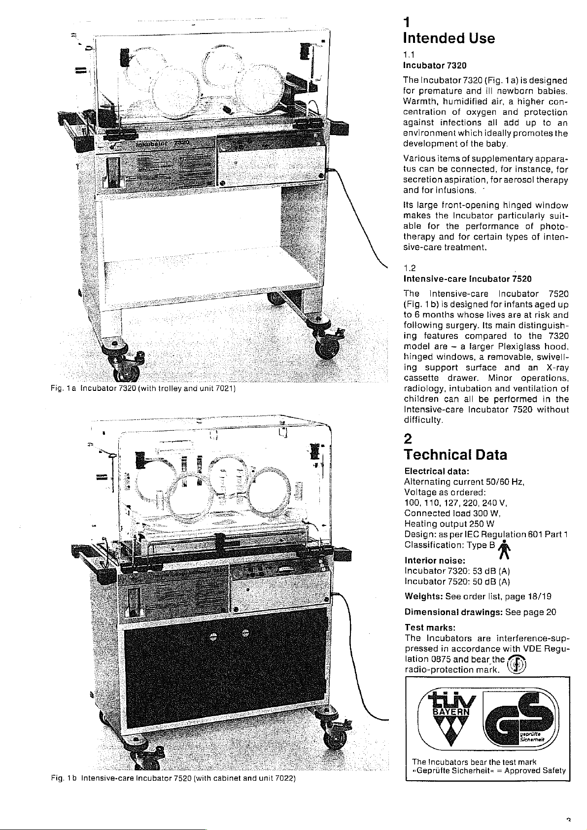
1
Intended
1.1
Incubator
The
for
Warmth,
centration
against
environment
development
Various
tus
secretion
and
Its
makes
able
therapy
sive-care
7320
Incubator
premature
humidified
infections
items
can
be
aspiration,
for
infusions.
large
front-opening
the
for
the
and
treatment.
Use
7320
(Fig.
and
ill
of
oxygen
which
ideally
of
the
of
supplementary
connected,
~
Incubator
performance
for
certain
1a)
is
designed
newborn
air, a higher
and
protection
all
add
up
promotes
baby.
for
instance,
for
aerosol
hinged
particularly
of
types
babies.
con-
to
appara-
therapy
window
suit-
photo-
of
inten-
an
the
for
1.2
Intensive-care
The
Intensive-care
(Fig.
1b)
to 6 months
following
ing
features
model
Fig.
1a
Incubator
7320
(with
trolley
and
unit
7021)
hinged
ing
cassette
radiology,
children
Intensive-care
difficulty.
are ~ a
windows, a removable,
support
Incubator
is
designed
whose
surgery.
compared
larger
surface
drawer.
intubation
can
all
Incubator
İts
be
,
7520
Incubator
for
infants
lives
are
main
to
Plexiglass
and
Minor
and
ventilation
performed
7520
7520
aged
up
at
risk
and
distinguish-
the
7320
hood,
swivell-
an
X-ray
operations,
of
in
the
without
2
Technical
Electrical
Alternating
Voltage
100, 110,
Connected
Heating
Design:
Classification:
Interior
Incubator
Incubator
Weights:
Dimensional
Test
The
pressed
lation
radio-protection
as
127,
output
as
noise:
See
marks:
Incubators
in
0875
Data
data:
current
ordered:
220,
load
300
250
perlEC
Type B ň
7320:
53
7520:
50
order
drawings:
are
accordance
and
bear
mark.
50/60
Hz,
240
V,
W,
W
Regulation
dB
dB
list,
interference-sup-
the
(A)
(A)
page
See
with
РУ
601
18/19
page
VDE
Part
20
Regu-
1
Fig.
1b
Intensive-care
Incubator
7520
(with
cabinet
and
unit
7022)
The
incubators
»Gepriifte
bear
the
test
Sicherheit« = Approved
mark
Safety
Page 4
3
Design
of
Operation
The
Incubator
on a mobile
Incubator
the
support
Plexiglass
The
air
circulating
adjustable,
ture,
control
and
oxygen
effective
infections.
firstly
perature
thermostat
element.
to
warm
functions
temperature
Depending
air
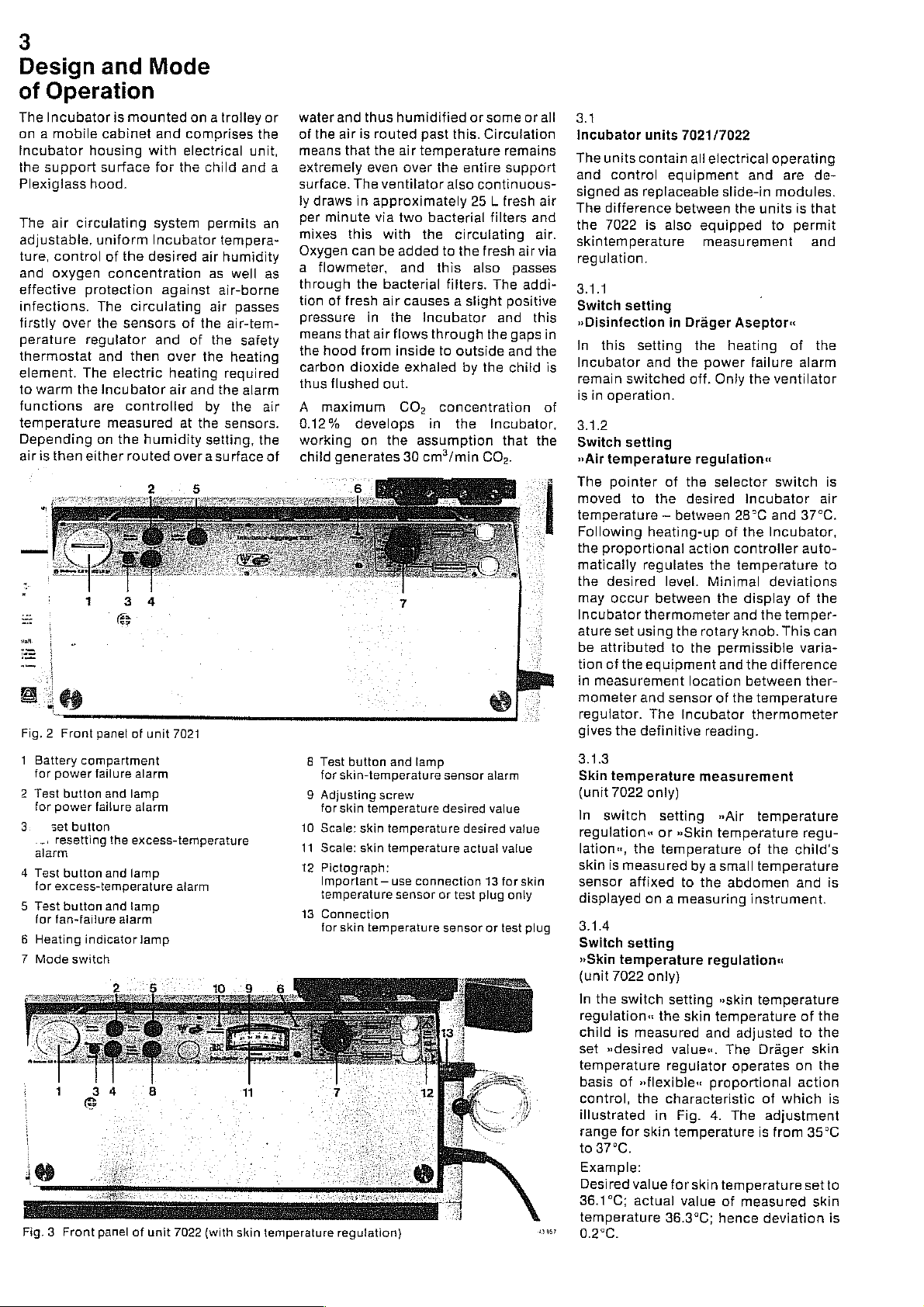
Fig. 2 Front
1
Battery
for
2
Test
for
3
..:
alarm
4
Test
for
5
Test
for
6
Heating
7
Mode
Fig.3 Front
protection
over
regulator
The
the
is
then
either
compartment
power
button
power
set
button
resetting
button
excess-temperature
button
fan-failure
indicator
switch
and
cabinet and
housing
surface
hood.
is
mounted
Mode
with
for
system
uniform
of
the
desired
Incubator
concentration
The
circulating
the
sensors
and
and
then
electric
Incubator
are
controlled
measured
on
the
humidity
routed
panel
of
unit
failure
alarm
and
lamp
failure
alarm
the
excess-temperature
and
lamp
and
lamp
alarm
lamp
panel
of
unit
on a trolley
comprises
electrical
the
child
permits
tempera-
air
humidity
as
well
against
over
heating
air
of
of
and
at
air-borne
air
the
the
the
required
the
by
the
sensors.
air-tem-
heating
the
setting,
over a surface
7021
alarm
7022
(with skin
or
the
unit,
and
an
as
passes
safety
alarm
air
the
of
temperature
a
water
and
of
the
air
means
that
extremely
surface.
ly
per
mixes
Oxygen
a
The
draws
minute
this
can
flowmeter,
through
tion
of
fresh
pressure
means
that
the
hood
carbon
thus
A
dioxide
flushed
maximum
0.12%
working
child
generates
8
Test
button
for
skin-temperature
9
Adjusting
for
skin
10
Scale:
11
Scale:
12
Pictograph:
Important — use
temperature
13
Connection
for
skin
regulation)
thus
humidified
is
routed
past
the
air
temperature
even
over
ventilator
in
approximately
via
two
with
the
be
added
and
the
bacterial
air
causes a slight
in
the
Incubator
air
flows
from
inside
exhaled
out.
CO,
develops
on
the
assumption
30
cm?/min
and
lamp
screw
temperature
skin
temperature
skin
temperature
connection
sensor
temperature
or
some
this.
Circulation
the
entire
also
continuous-
25 L fresh
bacterial
filters
circulating
to
the
fresh
this
also
filters.
The
and
through
to
the
outside
by
the
concentration
in
the
Incubator,
that
CO».
sensor
alarm
desired
value
desired
actual
vatue
13
or
test
sensor
for
plug
or test
or
alt
remains
support
air
and
air.
air
via
passes
addi-
positive
this
gaps
in
and
the
child
is
of
the
value
skin
only
plug
13957
3.1
Incubator
The
units
and
signed
The
the
skintemperature
units
contain
control
equipment
as
replaceable
difference
7022
is
also
7021/7022
all
electrical
between
equipped
measurement
regulation.
3.1.1
Switch
»Disinfection
In
Incubator
remain
is
setting
this
switched
in
operation.
in
setting
and
Drager
the
the
power
off.
Only
3.1.2
Switch
»Air
The
moved
setting
temperature
pointer
to
of
the
regulation«
the
selector
desired
temperature ~ between
Following
the
matically
the
may
Incubator
ature
be
attributed
tion
in
measurement
mometer
regulator.
gives
heating-up
proportional
regulates
desired
occur
set
of
the
level.
between
thermometer
using
the
equipment
and
sensor
The
definitive
action
the
Minimal
the
rotary
to
the
location
Incubator
reading.
the
permissible
and
of
3.1.3
Skin
temperature
(unit
7022
only)
In
switch
regulation«
lation,
skin
sensor
displayed
the
is
measured
affixed
on a measuring
measurement
setting
or
»Skin
»Air
temperature
temperature
by a small
to
the
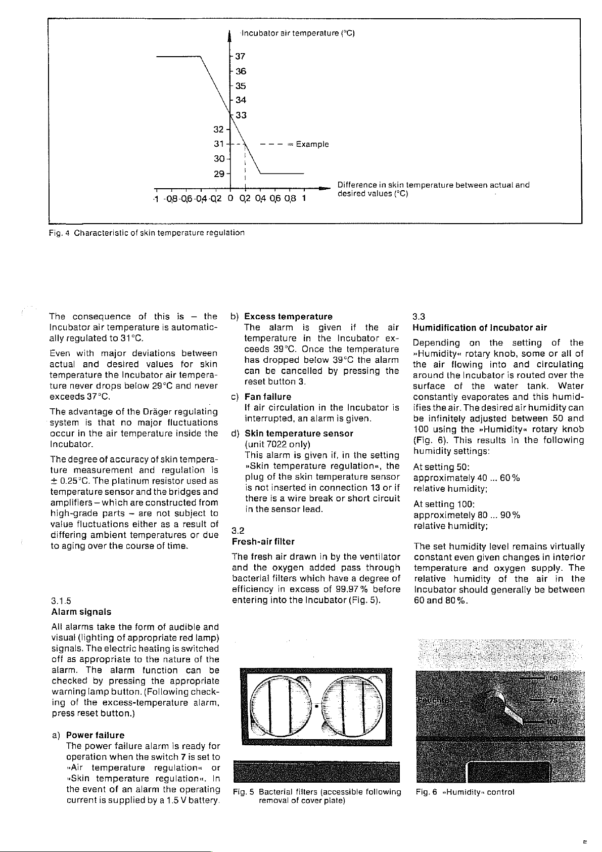
3.1.4
Switch
»Skin
(unit
In
regulation«
child
set
temperature
basis
control,
illustrated
range
to
36.1°C;
temperature
temperature
7022
the
switch
is
»desired
of
for
37°C.
Example:
Desired
setting
only)
setting
the skin
measured
value«.
regulator
»flexible«
the
characteristic
in
Fig.
skin
temperature
value
for
actual
36.3°C;
regulation«
»skin
temperature
and
proportional
4.
skin
value
hence
0.2°C.
operating
and
are
slide-in
the
modules.
units
to
Aseptor«
heating
failure
the
ventilator
of
switch
Incubator
28°C
and
of
the
Incubator,
controller
temperature
deviations
display
and
the
temper-
knob.
This
the
difference
between
the
temperature
thermometer
temperature
of
the
temperature
abdomen
instrument.
temperature
adjusted
The
Drager
operates
of
which
The
adjustment
is
from
temperature
of
measured
deviation
de-
is
that
permit
and
the
alarm
is
air
37°C.
auto-
to
of
the
can
varia-
ther-
regu-
child's
and
is
of
the
to
the
skin
on
the
action
is
35°C
set
to
skin
is
Page 5
‘Incubator
37
36
35
34
33
32
air
— — — =
temperature
Example
(°C}
Fig. 4 Characteristic
The
consequence
Incubator
ally
Even
actual
temperature
ture
exceeds
The
system
occur
Incubator.
The
ture
+
0.25°C.
temperature
amplifiers — which
high-grade
value
differing
to
aging
3.1.5
Alarm
Alt
visual
signals.
off
alarm.
checked
warning
ing
press
air
regulated
with
and
never
drops below
37°C.
advantage
is
that no
in
the
degree
alarms
as
of
measurement
The
fluctuations
ambient
over
signals
take
(lighting
The
appropriate
The
by
lamp
of
the
reset
temperature
to
31°C.
major
desired
the
Incubator
of
air
temperature
accuracy
platinum
sensor
parts — are
the
the
of
electric
alarm
pressing
button.
excess-temperature
button.)
4
-08-06-04-02 O 02 04 06
of
skin
temperature
of
this
is
deviations
vaiues
air
29°C
the
Drager
major
fluctuations
of
skin
and
regulation
resistor
and
the
bridges
are
constructed
not
either
as a result
temperatures
course
of
time.
form
of
audible
appropriate
heating
to
the
nature
function
the
appropriate
(Following
regulation
is — the
automatic-
between
for
skin
tempera-
and
never
regulating
inside
the
tempera-
is
used
as
and
from
subject
red
is
to
of
or
due
and
lamp)
switched
of
the
can
be
check-
alarm,
b)
Excess
The
alarm
temperature
ceeds
has
dropped
can
be
reset
button
Fan
failure
if
air
circulation
interrupted,
d)
Skin
temperature
{unit
7022
This
alarm
»Skin
plug
of
is
not
there
in
the
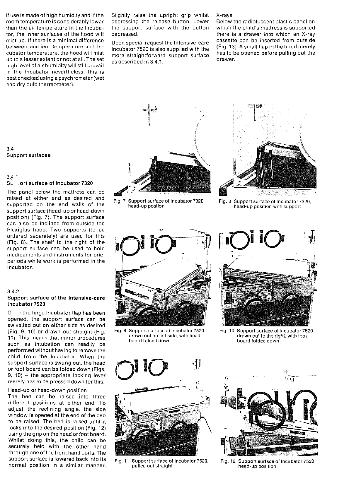
3.2
Fresh-air
The
fresh
and
the
bacterial
efficiency
entering
08
1
temperature
is
in
39°C.
Once
below
cancelled
3.
an
only)
is
given
temperature
the
skin
inserted
is a wire
sensor
oxygen
filters
into
filter
air
drawn
in
excess
the
lead.
which
Incubator
Difference
desired
given
the
Incubator
the
39°C
by
pressing
in
the
alarm
is
sensor
if,
in
regulation«,
temperature
in
connection
break
or
in
by
the
added
pass
have a degree
of
99.97%
in
skin
values
if
the
air
ex-
temperature
the
alarm
the
Incubator
given.
the
short
ventilator
(Fig.
setting
the
sensor
13
or
circuit
through
before
5).
is
of
temperature
(°C)
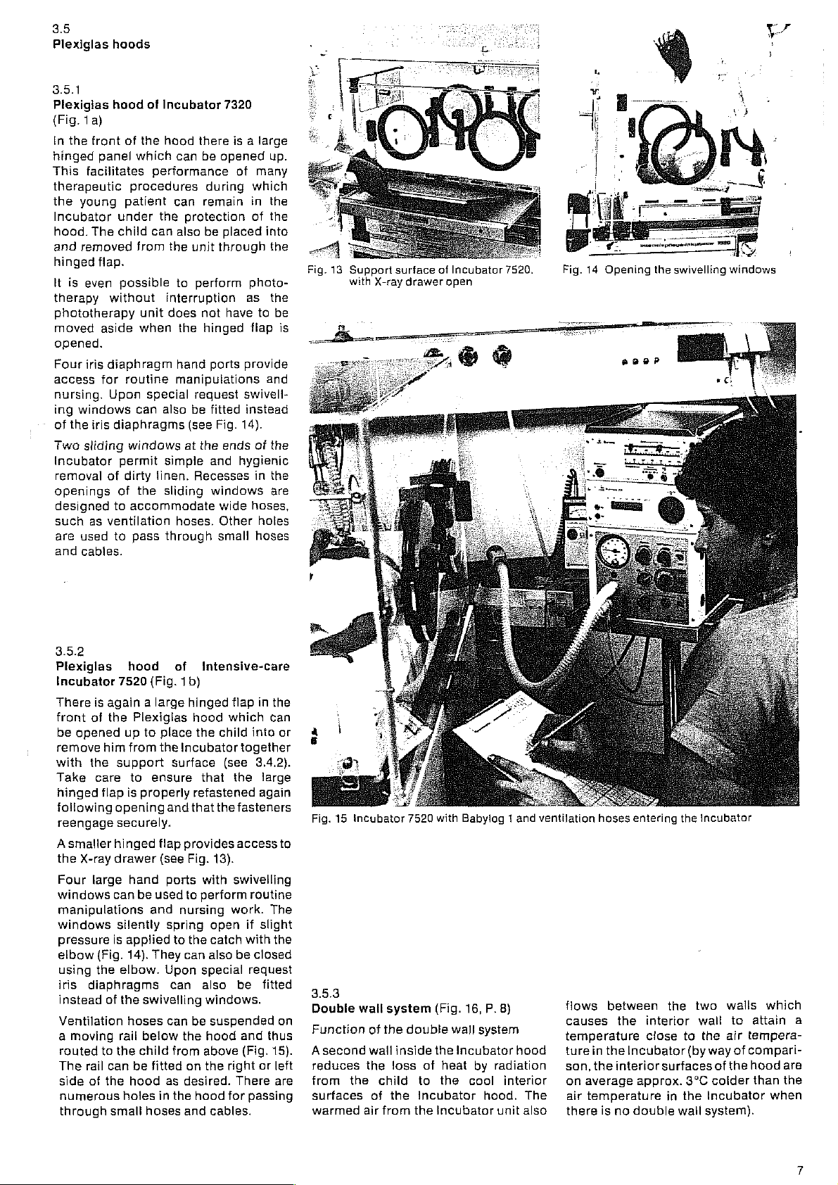
3.3
Humidification
Depending
»Humidity«
the
air
around
surface
constantly
ifies
the
be
infinitely
100
using
(Fig.
humidity
At
setting
approximately
if
relative
At
setting
approximeiely
relative
The
set
constant
temperature
relative
Incubator
60
and
between
rotary
flowing
the
Incubator
of
evaporates
air.
The
the
6).
This
settings:
50:
humidity;
100:
humidity;
humidity
even
humidity
should
80%.
actual
of
Incubator
on
the
knob,
into
the
water
desired
adjusted
»Humidity«
results
40
...
60%
80
...
90%
level
given
and
oxygen
of
generally
and
setting
some
and
is
routed
tank.
and
air
humidity
between
in
the
remains
changes
the
air
of
the
or
all
circulating
over
the
Water
this
humid-
can
50
and
rotary
supply.
following
virtually
in
interior
air
in
be
between
knob
The
the
of
a)
Power
The
operation
»Air
»Skin
the
current
failure
power
failure
when
temperature
temperature
event
of
is
supplied
an
the
alarm
alarm
is
ready
switch 7 is
regulation«
regulation«.
the
operating
by a 1.5 V
for
setto
or
In
battery.
Fig. 5 Bacterial
removal
filters
(accessible following
of
cover
plate)
Fig. 6 »Humidity«
control
Page 6
lf
use
is
made
of
room
temperature
than
the
air
temperature
tor,
the
inner
surfaces
mist
up.
If
there
between
cubator
up
high
in
best
and
34
Support
3.4
SL,
The panel
raised
supported
support
position)
can
Plexiglas hood.
ordered
(Fig.
support
medicaments
periods
Incubator.
ambient
temperature,
to à lesser
level
of air
the
Incubator
checked
dry
buib
surfaces
+
.ort
surface
below
at
either
surface
(Fig.
also
be
separately)
8).
The
surface
while
extent
using a psychrometer
thermometer).
on
inclined
high
humidity
is
considerably
of
is a minimal
temperature
the
or
not
humidity
nevertheless;
of
Incubator
the
mattress
end
as
the
end
(head-up
7).
The
from
Two
supports
are
shelf
to
the
can
be
and
instruments
work
is
performed
and
in
the
the
hood
difference
hood
at
all.
will
still
7320
desired and
walis
or
head-down
support
outside
used
right
used
if
the
lower
Incuba-
will
and
In-
will
mist
The
set
prevail
this
(wet
can
of
the
surface
the
(to
for
this
of
the
to
hold
for
brief
in
the
Slightly
depressing
the
depressed.
Upon
Incubator
more
as
is
be
be
raise
the
support
special
7520
straightforward
described
Fig. 7 Support
head-up
the
release
surface
request
is
also
in
3.4.1.
surface
postion
upright
button.
with
the
intensive-care
supplied
support
of
Incubator
grip
the
with
whilst
Lower
button
the
surface
7320,
X-rays
Below
the
radioluscent
which
the
child's
there
is a drawer
cassette
(Fig.
has
drawer.
é
Fig. 8 Support
can
13). A small
to
be
opened
head-up
be
surface
position
mattress
into
inserted
flap
in
before
of
with
plastic
is
supported
which
from
the
hood
pulling
Incubator
support
panel
an
X-ray
outside
merely
out
7320,
on
the
3.4.2
Support
Incubator
C > the
opened,
swivelled
{Fig.
9,
10)
11).
This
such
as
performed
child
from
support
or
foot
board
9,
10) — the
merely
Head-up
The
different
adjust
window
to
Whilst
securely
bed
be
raised.
locks
into
using
the
through
support
normal
has
the
doing
surface
7520
large
Incubator
the
support
out
on
or
drawn
means
intubation
without
the
surface
can
appropriate
to
be
or
head-down
can
positions
reclining
is
opened
The
the
desired
grip
on
this,
held
one
of
the
surface
position
of
the
Intensive-care
surface
either
side
out
that
minor
can
having
Incubator.
is
swung
be
folded
pressed
position
be
raised
at
either
angle,
at
the
end
bed
is
position
the
head
or
the
with
the
front
hand
is
lowered
in a
similar
flap
has
as
straight
procedures
readily
to
remove
When
out,
the
down
locking
down
into
end.
the
of
raised
foot
child
other
ports.
back
been
can
be
desired
(Fig.
be
the
the
head
(Figs.
lever
for
this.
three
To
side
the
bed
until
(Fig.
12)
board.
can
be
hand
The
into
its
manner.
Fig.9
Support
drawn
board
surface
out
on
folded
left
down
of
Incubator
side,
with
7520
head
Fig.
10
Support
drawn
board
surface
out
to
folded
the
down
of
Incubator
right.
with
7520
foot
it
e
E
nl
Fig.
11
Support
pulled
surface
out
straight
of
Incubator
7520,
Fig.
12
Support
head-up
surface
position
of
Incubator
7520.
Page 7
3.5
Plexiglas
3.5.1
Plexigias
(Fig.
1a)
In
the
front
hinged
This
therapeutic
the
Incubator
hood.
and
hinged
it
therapy
phototherapy
moved
opened.
Four
access
nursing.
ing
of
Two
Incubator
removal
openings
designed
such
are
and
panel
facilitates
young
The
removed
flap.
is
even
aside
iris
for
windows
the
iris
sliding
as
used
cables.
without
diaphragm
Upon
of
ventilation
hoods
hood
of
Incubator
of
the
hood
which
can
performance
procedures
patient
under
child
possible
routine
diaphragms
windows
permit simple
dirty
of
to
accommodate
to
pass
can
the
can
also
from
the
to
interruption
unit
does
when
the
hand
manipulations
special
can
also
linen.
the
sliding
hoses.
through
7320
there
is a large
be
opened
of
during
remain
protection
be
placed
unit
through
perform
not
have
hinged
parts
request
be
(see
at
the
Recesses
swivell-
fitted
Fig. 14).
ends
and
hygienic
windows
wide
Other
small
up.
many
which
in
the
of
the
into
the
photo-
as
the
to
be
flap
is
provide
and
instead
of
the
in
the
are
hoses,
holes
hoses
Fig.
14
Fig.
13
Support
with
X-ray
surface
drawer
of
Incubator
open
7520,
Opening
the
swivelling
windows
3.5.2
Plexiglas
Incubator
There
front
be
opened
remove
with
Take
hinged
following
reengage
A
smaller
the
X-ray
Four
windows
Manipulations
windows
pressure
elbow
using
iris
instead
Ventilation
a
moving
routed
The
side
numerous
through
hood
7520
is
again a large
of
the
up
him
from
the
support
care
to
flap
is
opening
securely.
hinged
drawer
large
hand
can
silently
is
applied
(Fig.
14).
the
elbow.
diaphragms
of
the
hoses
rail
to
the
rail
can
of
the
hood
holes
small
of
(Fig.
1b)
Plexiglas
to
place
the
Incubator
surface
ensure
properly
and
flap
(see
ports
be
used
and
nursing
spring
to
They
Upon
can
swivelling
can
below
child
from
be
fitted
as
in
the
hoses
intensive-care
hinged
that
provides
Fig.
to
the
can
the
on
desired.
and
flap
hood
which
the
child
together
(see
that
the
refastened
the
fasteners
access
13).
with
swivelling
perform
work. The
open
catch
also be
special
also
be
windows.
be
suspended
hood
and
above
(Fig.
the
right
There
hood
for
cables.
in
the
can
into
or
3.4.2).
large
again
to
routine
if
slight
with
the
closed
request
fitted
on
thus
15).
or
left
are
passing
Fig.
15
incubator
3.5.3
Double
Function
Asecond
reduces
from
the
surfaces
warmed
wall
air
of
the
wail
the
child
of
from
7520
system
double
inside
!oss
the
the
with
Babylag 1 and
(Fig.
16,
wall
the
Incubator
of
heat
to
the
cool
incubator
Incubator
P.
system
by
radiation
hood.
unit
ventilation
8)
hood
interior
The
also
hoses
flows
between
causes
temperature
turein
son,
on
air
there
the
the
Incubator
the
interior
average
temperature
is
no
entering
the
interior
close
surfaces
approx.
in
double
the
incubator
two
wall
to
(by
3°C
the
wail
walls
to
the
air
way
of
of
the
colder
Incubator
system).
which
attain
tempera-
compari-
hood
are
than
the
when
a
Page 8
The
child
is
on
the
sides
particularly
premature
1500 g as
hypothermia
radiation.
convection
reduced
and/or
humidity.
Description
The
the
Incubator
7520 — with
being
The
sections — an
straight,
attached
Access
ports
obstructed
the..inner
ap
The
removed
ed
bolts
walls
Incubator
outside
babies
it
Further
by
raising
double
possible.
interior
flat
to
to
the
in
the
by
uresin
inner
rapidly
permanently
are
pushed
with
surrounded
and
at
the
valuable
weighing
guards
as a result
and
raising
wall
supplementary
wall
pane,
the
walls
the
walls
hood
knurled
against
heat
evaporation
the
the
degree
system
hoods
of
system
L-shaped
with
large
hinged
child
through
Incubator
the
double
also
same
can
and
easily.
through
and
nuts.
loss
positions.
fitted
by
warm
top.
in
the
less
the
of
heat
as a result
has
air
temperature
of
is
available
modets
fitting
comprises
section and
the
latter
flap.
hood
wall
system
feature
be
fitted
The thread-
to
holes
secured
wails
This
case
than
risk
loss
to
relative
7320
being
the
hand
is
large
the
inner
in
is
of
of
by
of
be
for
and
also
two
not
as
and
the
from
a
Fig.
16
Double
wail
system
in
the
|
|
/
hood
of
Intensive-care
|
Incubator
7520
Subsequent
Holes
have
hood
to
permit
double
be
Branch
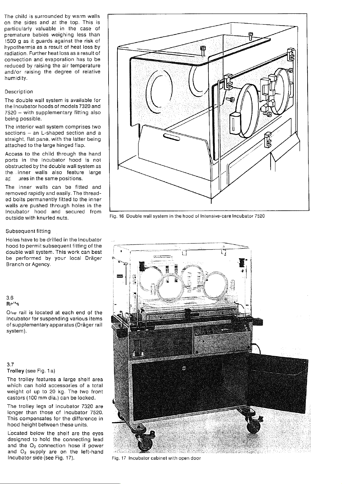
3.6
Ars
One
Incubator
of
system).
3.7
Trolley
The
which
weight
The
This
wall
performed
or
rail
supplementary
(see
trolley
can
of
castors
longer
hood
Located
designed
and
and
Incubator
(100
trolley
than
compensates
height
the
O,
fitting
to
be
drilled
subsequent
system.
Agency.
is
located
for
Fig.
features a large
hold
up
legs
below
to
O;
supply
side
This
by
your
at
suspending
apparatus
1a)
accessories
to
20
kg.
mm
dia.)
of
Incubator
those
of
for
between
the
shelf
hold
the
connection
are
(see
Fig.
in
the
Incubator
fitting
work
local
each
end
various
(Dräger
shelf
of a total
The
two
can
be
locked.
Incubator
the
difference
these
units.
are the
connecting
hose
on
the
17).
of
the
can
best
Drager
of
the
items
rail
area
front
7320
are
7520.
in
eyes
lead
if
power
left-hand
Fig.
17
Incubator
cabinet
with
open
door
Page 9

3.8
Accessories
{on
special
3.8.4
Cabinet
The
trolley
The
doors
applying
All
doors
which
weighing
Larger
be
stored
The
longer
This
hood
3.8.2
O,
metering
The
incubator
tor
via a metering
a
connection
The
attached
means
humidify
achieved
order)
(Figs.
cabinet
with
doors
can
pressure
are
can hold
up
items
on
the
cabinet
compensates
oxygen
metering
than
height
air
to
of
aclamp.
the
inside
legs
between
(Fig.
the
1b
and
can
be
on
be
opened
(e.
fitted
to
max. 1 kg
weighing
bottom
of
those
for
18)
required
is
routed
vaive
socket
valve
incubator
It
oxygen
the
17)
described
the
front
and
and
closed
g.
with
the
with
18796
medicaments
(Fig.
up
to
20
of
fhe
cabinet.
Incubator
of
Incubator
the
these
into
and a rubber
and
is
not
as this
Incubator.
difference
units.
to
enrich
the
with
flowmeter.
flowmeter
rail
(Fig.
necessary
7320
is
as
back.
by
knee).
pockets
etc.
17).
kg
can
are
7520.
the
incuba-
hose.
are
18) by
ideally
3.8.5
Water
See
The
tion
spontaneously
aerosols
a
micron).
When
tion
infinitely
100%.
breathing
operates
Nebulizer
the
breathing
point
in
temperature.
nebulizer
increases
original
Nebulizer
to
nebulizer
relevant
water
of
using
af
the
If
with
correct
of
level.
(Fig.
21)
Operating
nebulizer
the
breathing
{average
oxygen
Manual.
permits
breathing
particle
the
breathing
adjusted
no O;
gas
heating
conditions
gas
view,
performance
to
operation
between
enrichment
is
desired
compressed
is
available
in
from a physiological
including
If
the
heating
two
or
three
causes
humidifica-
air
of
the
child
with
size
0.65
O;
concentra-
gas
can
40
and
of
the
the
nebulizer
air.
to
create
the
humidified
the
correct
is
used
simultaneously
times
the
modifica-
be
tion
of
the
the
Table
in
The
O,
concentration
Incubator
O,
meter
(see
Section
Nebulization
in
These
applied
nebulizer
the
5.3).
form
substances
in
advantages
backs
and
remembered
be
deposited
apparatus
strong
tendency
Regular
Incubator
order
to
reduce
the
child.
Please
the
observe
substances
O,
concentrations
Section
must
be
determined
also
of
expectorant
of
aqueous
the
Incubator
in
cases
clearly
hazards
that
these
on
and
that
thorough
is
absolutely
the
instructions
employed.
5.3.
prevailing
the
relevant
solutions.
should
with
where
the
outweigh
involved.
substances
ali
surfaces
the
residue
to
develop
cleaning
imperative
risk
of
shown
in
using
notes
substances
only
the
water
expected
the
draw-
It
must
of
has
fungus.
of
infection
for
use
in
the
an
in
be
be
wil!
the
a
the
in
for
of
3.8.3
Oxygen
An
the
screwed
meter
limiter
oxygen
Incubator.
onto
(3.8.2)
limiter
the
in
socket.
Two
switch
handwheel
a)
White
QO,
for
into
to
approx.
if a lower
supply
at
b)
Red
supply.
3.8.4
Oxygen
A
Plexiglas
ter
high
child
of
acute
into
the
(setting
nebulizer
If
an
desired a nappy
around
settings
of
the
setting:
metering
more
than 6 L/min
the
Incubator.
an
oxygen
40%.
O,
rate
of
the
metering
setting:
helmet
helmet
concentrations
as
quickly
asphyxia.
helmet
approx.
and a corrugated
extremely
the
child's
(Fig.
19)
can
be
connected
The
bottom
piace
limiter:
even
valve
oxygen
of
can
it
limiter
of
the
the
connection
be
fixed
with a fuliy-open
is
not
oxygen
This
corresponds
concentration
content
fess
no
(Fig.
as
The
via
the
10
high
neck
is
required,
than 6 L/min
valve.
restriction
20}
is
used
to
of
oxygen
possible
L/min), a humidifier/
O;
must
in
oxygen
O2
metering
hase.
concentration
be
to
create a seal.
to
is
O:
flow-
at
the
possible
to
flow
of
is
set
of
O;
adminis-
to
the
the
case
is
routed
valve
is
wrapped
a
Fig.
20
Oxygen
helmet
Fig.
21
Water
nebulizer
with
heater
Page 10
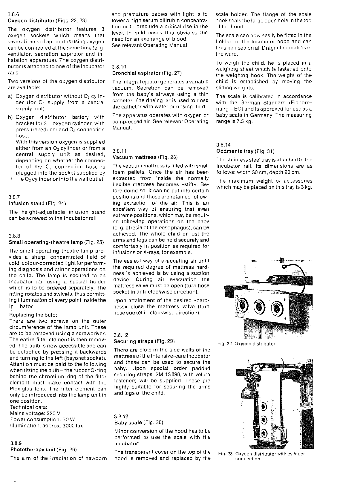
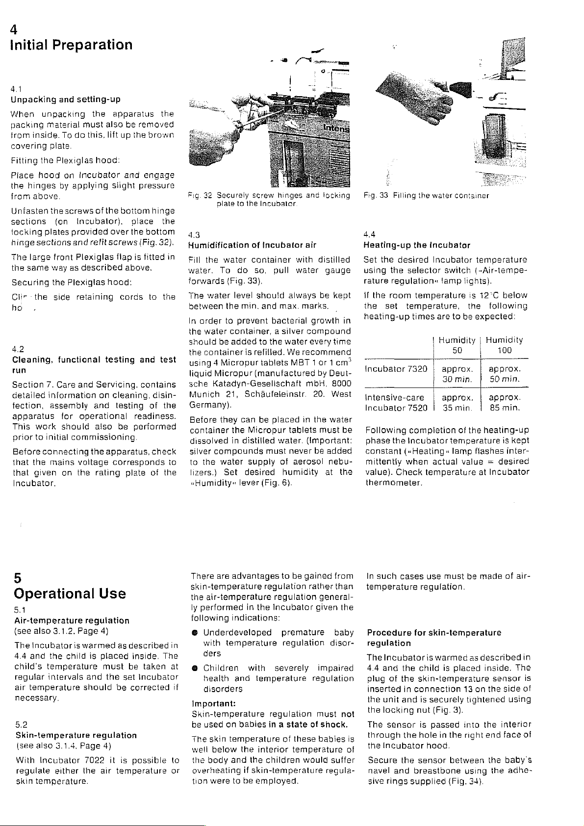
3.8.6
Oxygen
The
oxygen
several
can
ventilator,
halation
butor
rails.
Two
are
a)
b)
3.8.7
Infusion
The
can
distributor
oxygen
sockets
items
of
be
connected
secretion
apparatus).
is
attached
versions
available:
Oxygen
der
suppiy
Oxygen
bracket
pressure
hose.
With
either
central
depending
tor
plugged
.e
(for
this
of
O,
distributor
O,
unit).
distributor
for
reducer
version
from
supply
the
into
cylinder
stand
height-adjustable
be
screwed
3.8.8
Smali
operating-theatre
The
smal!
operating-theatre
vides a sharp,
cold,
colour-corrected
ing
diagnosis
the
child.
The
incubator
which
fitting
ing
illumination
Ir
tbator.
Replacing
There
circumference
are
to
The
ed.
The
be
detached
and
Attention
when
behind
element
Plexiglas
only
one
Technical
Mains
Power
illumination:
3.8.9
Phototherapy
The
rail
is
to
rotates
the
are
be
removed
entire
filter
buib
turning
must
fitting
the
must
lens.
be
intreduced
position.
data:
voltage:
consumption:
aim
of
be
two
to
the
chromium
the
(Figs.
22,
distributor
which
apparatus
at
the
using
same
aspirator
The
oxygen
to
one
of
the
of
the
oxygen
without
supply
from a central
battery
3 L
öxygen
an
Os
on
whether
O:
connection
the
or
(Fig.
and
O,
oxygen
cylinder
unit
socket
into
the
24)
cylinder.
infusion
to
the
Incubator
lamp
concentrated
light
and
minor
operations
lamp
is
secured
using a special
ordered
and
of
bulb:
screws
of
element
is
now
by
pressing
the
be
separately.
swivels,
every
point
on
the
lamp
using a screwdriver.
is
accessible
teft
(bayonet
paid
to
bulb — the
ring
make
contact
The
filter
into
the
220
V
50
W
approx.
3000
unit
(Fig.
irradiation
26)
23)
features
means
time
Incubator
that
oxygen
(e.
and
distri-
3
g.
in-
distributor
O;
cylin-
with
with
connection
is
supplied
or
from
a
as
desired,
the
connec-
hose
is
supplied
wall
by
outlet.
stand
rail.
(Fig.
25)
lamp
pro-
field
of
for
perform-
on
to
an
holder
The
thus
permitt-
inside
the
the
outer
unit.
These
then
remov-
and can
it
backwards
socket).
the
following
rubber O-ring
of
the
filter
with
the
element
lamp
lux
of
can
unit
newborn
in
and
premature
lower a high
tion
or
to
preciude a critical
level.
In
mild
need
for
an
See
relevant
3.8.10
Bronchial
The
integral
vacuum.
from
catheter.
the
The
compressed
Manual.
Secretion
the
baby's
The
catheter
apparatus
3.8.11
Vacuum
The
foam
extracted
flexible
fore
positions
ing
exceltent
extreme
ed
(e.g.
mattress
vacuum
pellets.
mattress
doing
and
extraction
positions,
following
atresia
achieved.
arms
and
legs
comfortably
infusions
The
the
ness
device.
mattress
socket
Upon
ness«
hose
or
easiest
required
is
achieved
During
valve
in
anti-clockwise
attainment
close
socket
3.8.12
Securing
There
are
mattress
and
baby.
securing
fasteners
highly
and
these
Upon
suitable
legs
of
straps,
of
3.B.13
Baby
scale
Minor
conversion
performed
Incubator:
The
transparent
hood
is
removed
babies
serum
cases
exchange
Operating
aspirator
ejector
rinsing
with
water
operates
air.
See
mattress
Once
from
so,
it
can
these
of
way
of
operations
of
the
The
whole
can
in
position
X-rays,
way
of
degree
must
the
in
clockwise
straps
(Fig.
slots
in
the
Intensive-care
can
be
special
will
be
for
the
child.
(Fig.
to
use
cover
with
light
bilirubin
(Fig.
generates a variable
airways
relevant
(Fig. 28)
inside
becomes
be
are
the
ensuring
which
oesophagus),
be
for
evacuating
is
by
air
be
of
the
mattress
concentra-
rise
this
obviates
of
blood.
Manual.
27)
can
be
removed
using a thin
jar
is
used
to
or
rinsing
with
oxygen
Operating
is
filled
with
the
air
has
the
normally
»stiff«.
put
into
retained
air.
This
that
may
be
on
the
child
or
just
held
securely
as
required
example.
air
of
mattress
using a suction
evacuation
open
(turn
direction}.
desired
valve
in
fluid.
small
certain
follow-
is
requir-
can
»hard-
direction).
29)
the
side
walls
of
Incubator
used
to
secure
2M
13898,
supplied.
securing
30)
of
the
the
and
order
hood
scale
on
replaced
the
with
These
the
has
with
top
padded
velcro
by
is
to
the
the
rinse
or
been
Be-
an
even
baby
be
the
and
for
until
hard-
the
hose
(turn
the
the
are
arms
to
be
the
of
the
the
scale
holder.
hook
seals
of
the
hood.
The
scale
holder
thus
be
the
ward.
To
weigh
weighing
the
weighing
child
is
sliding
The
scale
with
the
nung — EO)
baby
scale
range
is
the
can
now
on
the
used
on
the
sheet
established
weights.
is
calibrated
German
and
in
Germany.
7.5
kg.
The
flange
large
open
easily
Incubator
all
Drager
child,
he
which
hook.
The
Standard
is
approved
of
hole
be
fitted
hood
Incubators
is
placed
is
fastened
weight
by
moving
in
accordance
for
The
measuring
the
scale
in
the
top
in
the
and
can
in
onto
of
the
the
(Eichord-
use
as
in
a
a
3.8.14
Oddments
The
Incubator
follows:
The
which
tray
stainless
rail.
width
maximum
may
be
(Fig.
steel
tray
Its
30
cm,
weight
placed
31}
is
attached
dimensions
depth
20
of
accessories
on
this
cm.
tray
to
the
are
as
is 3 kg.
Fig. 23
Oxygen
connection
distributor
with
cylinder
Page 11

Fig.
27
Fig.
30
Bronchial
Sliding-weight
aspirator
baby
scale
Fig.
31
Oddments
tray
Fig.
29
Fastening
the
securing
straps
11
Page 12
4
initial
4.1
Unpacking
When
packing
from
covering
Fitting
Place
the
from
Unfasten
sections
locking
hinge
The
the
Securing
Clir
ho
4.2
Cleaning,
Preparation
unpacking
material
inside.
plate.
the
Plexiglas
hood
hinges
above.
thescrews
(on
plates
sections
large
front
same
way
the
the
side
functional
run
Section
detailed
fection,
apparatus
This
prior
Before
that
that
7.
Care
information
assembly
work
to
initial
connecting
the
mains
given
Incubator,
and
setting-up
the
must
To
do
this,
hood:
on
Incubator
by
applying
of
the
incubator),
provided
and
refit
Plexiglas
as
described
Plexiglas
retaining
testing
and
Servicing.
on
and
for
operational
should
aiso
commissioning.
the
apparatus,
voltage
on
the
rating
apparatus
also
be
removed
lift
up
the
and
slight
pressure
bottom
place
over
the
screws
(Fig.
fiap
is
above.
hoad:
cords
cleaning,
testing
readiness.
be
performed
corresponds
plate
the
brown
engage
hinge
the
bottom
32).
fitted
in
to
the
and
test
contains
disin-
of
the
check
to
of
the
Fig.
32
Securely
plate
43
Humidification
Fill
the
water.
forwards
The
To
water
between
In
order
the
water
should
the
sche
be
container
using 4 Micropur
liquid
Micropur
Katadyn-Geselischaft
Munich
Germany).
Before
they
container
dissolved
silver
compounds
to
the
water
lizers.)
»Humidity«
screw
to
the
water
do
(Fig.
33).
level
the
min.
to
prevent
container, a silver
added
is
21,
Scháufeleinstr.
can
the
in
distilled
Supply
Set
desired
lever
hinges
Incubator
of
incubator
container
so,
pull
should
refilled.
tablets
(manufactured
and
bacterial
to
the
be
placed
always
max.
water
We
Micropur
water.
must
of
humidity
(Fig.
6).
and
locking
air
with
distilled
water
gauge
be
kept
marks.
growth
compound
every
time
recommend
MBT 1 or 1 em?
by
Deut-
mbH,
8000
20.
West
in
the
water
tablets
never
must
(Important:
be
aerosol
added
nebu-
at
the
Fig.
4.4
Heating-up
Set the
using
rature
if
the
heating-up
in
Incubator
intensive-care
Incubator
Following
be
phase
consiant
mittentiy
value).
thermometer.
33
Filling
the
regulation«
the
room
set
the
the
the
desired
selector
temperature
temperature,
times
7320 | approx.
7520 | 35
compietion
Incubator
(»Heating«
when
Check
water
container
Incubator
Incubator
switch
lamp
are
Humidity | Humidity
30
approx.
actual
temperature
temperature
(«Air-tempe-
lights).
is
12°C
the
to
be
expected:
50
min.
min.
of
the
heating-up
temperature
lamp
flashes
value = desired
at
below
following
100
approx.
50
min.
approx.
85
min.
is
kept
inter-
Incubator
5
Operational
5.1
Air-temperature
(see also
The
4.4
child's
regular
air
3.1.2,
incubatoris
and
the
temperature
intervals
temperature
necessary.
5.2
Skin-temperature
(see also
With
regulate
skin
3.1.4,
Incubator
either
temperature.
regulation
Page
warmed
child
and
should
Page
7022
the
Use
4)
as
is
placed
must
the
be
regulation
4)
it
is
air
temperature
described
inside.
be
taken
set
incubator
corrected
possible
There
skin-temperature
the
ly
following
@
in
The
at
e
if
Important:
Skin-temperature
be
The
well
to
the
or
overheating
tion
are
advantages
air-temperature
performed
Underdeveloped
with
ders
Children
health
disorders
used
skin
below
body
were
in
indications:
temperature
with
and
on
babies
temperature
the
and
if
to
be
to
be
gained
regulation
regulation
the
Incubator
premature
regulation
severely
temperature
regulation
in a state
of
these
interior
the
skin-temperature
employed.
temperature
children
would
from
rather
than
general-
given
baby
disor-
impaired
regulation
must
of
shock.
babies
suffer
regula-
the
not
is
of
In
such
cases
temperature
Procedure
regulation
The
Incubator
4.4
and
the
plug
of
the
inserted
the
the
The
through
the
Secure
navel
sive
in
unit
and
locking
sensor
the
Incubator
the
and
rings
supplied
use
must
be
regulation.
for
skin-temperature
is
warmed
child
is
placed
skin-temperature
connection
is
securely
nut
(Fig.
is
passed
hole
3).
in
the right
13
tightened
into
hood.
sensor
breastbone
between
using
(Fig.
made
as
described
inside.
on
the
the
end
the
34).
of
sensor
side
using
interior
face
baby's
the
adhe-
air-
in
The
is
of
of
Page 13
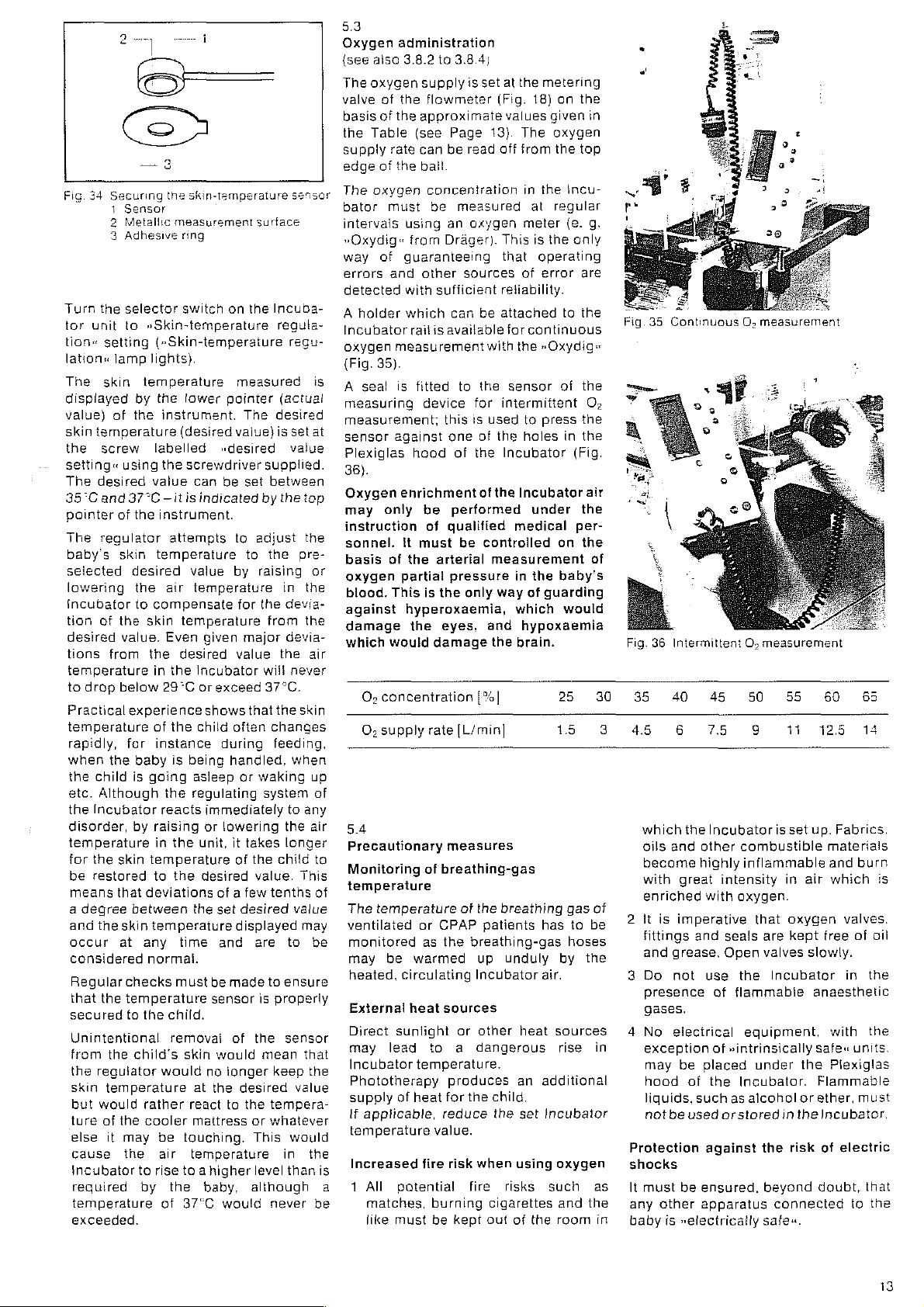
Fig.
34
Securing
1
Sensor
2
Metallic
3
Adhesive
Turn
the
selector
tor
unit
to
tion«
setting
lation«
The
displayed
value)
skin
the
setting«
The
35°C
pointer
The
baby's
selected
incubator
tion
desired
tions
Practical
lamp
skin
of
temperature
screw
using
desired
and
37°C — itis
of
regulator
skin
lowering
of
the
value.
from
temperature
to
drop
below
experience
temperature
rapidly,
when
the
etc.
the
disorder,
temperature
for
be
means
a
and
occur
considered
Regular
that
secured
the
child
Although
Incubator
the
skin
restored
that
degree
the
skin
at
the
for
checks
temperature
to
by
the
the
desired
the
to
baby
is
by
between
Unintentional
from
the
child’s
the
reguiator
skin
temperature
but
would
ture
of
the
else
it
may
cause
Incubator
required
temperature
exceeded.
the
to
the
skin-temperature
measurement
ring
switch
on
»Skin-temperature
(»Skin-temperature
lights}.
temperature
the
lower
instrument.
(desired
labelled
the
screwdriver
value
instrument.
attempts
temperature
air
compensate
skin
temperature
Even
the
desired
in
the
29°C
of
the
instance
is
being
going
the
reacts
raising
in
the
temperature
to
the
deviations
temperature
any
time
normal.
must
the child.
removai
skin
would
rather
cooler
be
touching.
air
rise
to a higher
by
the
of
37°C
measured
pointer
The
vaiue)
«desired
can
be
set
indicated
to
to
value
by
temperature
for
given
major
value
Incubator
or
exceed
shows
that
child
often
during
handled,
asleep
or
regulating
immediately
or
lowering
unit,
it
takes
of
desired
of a few
the
set
desired
displayed
and
be
made
sensor
of
would
no
ionger
at
the
desired
react
to
the
mattress
temperature
baby,
would
surface
the
Incuba-
regula-
(actual
desired
is
supplied.
between
by
the
adjust
the
raising
in
the
devia-
from
devia-
the
will
37°C.
the
changes
feeding.
waking
system
the
longer
the
child
value.
tenths
are
to
ensure
is
properly
the
sensor
mean
keep
tempera-
or
whatever
This
in
level
than
although
never
sensor
regu-
is
set
at
value
top
the
pre-
or
the
the
air
never
skin
when
up
of
to
any
air
to
This
of
value
may
to
be
that
the
value
would
the
is
be
5.3
Oxygen
(see
The
valve
basis
the
supply
edge
The
bator
intervals
»Oxydig«
way
errors
detected
A
holder
Incubator
oxygen
(Fig.
A
seal
measuring
measurement;
sensor
Plexiglas
36).
Oxygen
may
instruction
sonnel.
basis
oxygen
blood.
against
damage
which
O;
O;
5.4
Precautionary
Monitoring
temperature
The
ventilated
monitored
may
heated,
External
Direct
may
Incubator
Phototherapy
supply
lf
applicable,
temperature
Increased
1
All
a
matches,
like
administration
also
3.8.2
to
oxygen
Table
oxygen
supply
of
the
of
the
approximate
(see
rate
can
of
the
ball.
must
using
from
of
guaranteeing
and
other
with
which
rail
measurement
flowmeter
concentration
be
sufficient
is
35).
is
fitted
device
against
hood
enrichment
only
be
of
it
must
of
the
arterial
partial
This
is
the
hyperoxaemia,
the
eyes,
would
damage
concentration
supply
temperature
be
rate
of
breathing-gas
or
CPAP
as
the
warmed
circulating
heat
sunlight
lead
to a dangerous
temperature.
of
heat
reduce
value.
fire
potential
burning
must
be
3.8.4)
is
set
(Fig.
Page
18).
be
read
off
measured
an
oxygen
Drager).
can
available
this
one
of
performed
qualified
pressure
sources
be
with
to
the
for
is
used
of
the
of
the
be
controlled
measurement
only
This
that
reliability.
attached
intermittent
the
way
and
the
[%]
[L/min]
measures
of
the
breathing
patients
breathing-gas
up
Incubator
sources
or
other
produces
for
the
child.
the
risk
when
fire
cigarettes
kept
out
at
the
metering
18)
values
given
The
from
in
the
at
meter
is
the
operating
of
error
for
continuous
the
»Oxydig«
sensor
to
press
holes
Incubator
Incubator
under
medical
in
the
of
guarding
which
hypoxaemia
brain.
has
unduly
air.
heat
an
additional
set
Incubator
using
risks
such
of
the
on
the
in
oxygen
the
top
incu-
regular
(e.
g.
only
are
to
the
of
the
O:
the
in
the
(Fig.
air
the
per-
on the
of
baby’s
would
Fig.
25 30 35
15
3
45
gas
of
be
the
in
as
the
in
2
3
4
Protection
shocks
lt
any
baby
to
hoses
by
sources
rise
oxygen
and
room
36
Intermittent
40 45
6
which
oils
and
become
with
enriched
it
is
imperative
fittings
and
grease.
Do
not
presence
gases.
No
electrical
exception
may
hood
liquids,
not
be
must
other
is
O,
50 55
75
the
Incubator
other
combustible
highly
inflammable
great
intensity
with
oxygen.
and
seals
Open
use
the
of
flammabie
equipment,
of
»intrinsically
be
placed
of
the
Incubator.
such
as
alcohol
used
orstored
against
be
ensured,
apparatus
»electricatly
measurement
9
11
is
set up.
in
that
oxygen
are
kept
valves
Incubator
under
the
or
in
the
the
risk
beyond
connected
safe«.
60
Fabrics,
materials
and
burn
air
which
valves.
free
of
slowly.
in
anaesthetic
with
safe«
units.
Plexiglas
Flammable
ether,
must
Incubator.
of
electric
doubt,
to
65
is
ail
the
the
that
the
13
Page 14

6
Trouble
Fault
»Power
depressed — buzzer
Power
sounds. warning
button
Buzzer
does
Red
lamp
buzzer
failure»
Warning
»Excess
»Fan
lamp
liyats,
Incubator
preset
For
Water
marker
not visible:
Oxygen
when
Table
using
Oxygen
when
No
lamp does
failure
temperatures
depressed
does
not
light
»excess
lights.
failures
does
does
»fan
fallure«
buzzer
does
temperature
skin-temperature
»Skin-temperature
button
depressed:
Buzzer
does
does
not
Red
»skin-temperature
warning
Skin-temperature
wkin-temperature
No
regulation
level
of
concentration
adjusted
on
P.
oxygen
concentration
set
according
oxygen
Shooting
test
does
not
alarm:
lamp
not
sound,
temperature“
buzzer
sounds
test
button
not
sound,
not
light
warning
sounds
not
attain
not
sound,
light
lamp
lights.
of
skin
is
below
the
sight
glass
in
accordance
13
{can
be
meter}
flow
button
not
light
buzzer
lights
test
lamp
depressed:
lamp
regulation
sensors
lamp
sensor«
buzzer
display
display
temperature
the
bottom
or
too
determined
tao
to
Table
sound
warning
only:
test
sounds
shows
too
tow
is
high
with
low
minimum
Possible
Battery
Battery
Battery
Selector
»Disinfection
Alarm
Bulb
Mains
Power
Selector
Bulb
defective
Previously
alarm
Heating
sunlight.
Defective
the
above
Selector
Bulb
Fan
correctly
Motor
Excessive
Incubator
Room
Hand
Brown
incorrectly
Selector
or
Bulb
Skin-temperature
properly
Sensor
short
Sensor
Sensor
Selector
temperature
Too
Interrupted
fresh
Fan
Motor
Bacterial
Hand
Seals
interior
Screws
valve
cause
position
flat
contacts
switch
in
function
defective
plug
pulled
supply
failure
switch
defective.
triggered
test
not
yet
of
Incubator
radiator
temperature
Incubator
defective,
impeller
vair-temperature
defective.
little
impeller
»Wrong«
Metering
Oxygen
unit
empty
Oxygen
connected
temperature
set
value.
switch
missing
attached
defective
external
standing
too
cold
ports
open
covering
switch
connected
defective
circuit)
still
too
not
propertly
switch
regulation«
water
or
air:
not
defective
filters
air
flowing
port
open,
between
of
Incubator
of
unit
valve
not
open
cylinder,
connecting
incorrect
corroded
in
»off«
Drager
defective
out
in
»off«
alarm
function
alarm
cancelled
from
close
regulator.
in
»off«
alarm
function
or
cooling:
in
draught
plate
fitted
in
»oft«,
regulation«
alarm
function
sensor
(wire
break
cold
secured
not
in
»skin-
in
water
impaired
properly
clogged
into
flap
open
base
unit
not
loose
or
oxygen
oxygen
hoses
setting
Aseptor«
setting
or
outside:
by
rises
setting
defective.
not
“Aseptore
not
or
to
setting
container
supply
secured
Incubator:
and
O.K,
cylinder
supply
nat
or
setting
setting.
defective
child
of
Remedy
Turn
positive
Replace
batteries).
Selector
regulation«
regulation
Contact
Contact
Plug
in
Check
Put
selector
regulation«
regulations
Contact
Depress
Move
follawing
Shut
down
Drager
Put
selector
regulations
regulations
Contact
Fitand
impeller
Shut
down
Drager
Eliminate
increase
Ciose
Fit
covering
Put
selector
regulation«
Contact
Plug
in
lock
nut.
Connect
Switch
until
fauit
Wait
for
Correctly
Set
selector
regulation
Top
up
Fit
and
Shut
Drager
Replace
Close
Following
or
contact
Branch/Agency
Tighten
of
the
Open
Provide
Connect
terminal
battery
(use only
Clean
switch
to
or
»skin-temperature
setting
nearest
iuse
Incubator
Branch/Agency
securely
Branch/Agency.
hand
sensor
over
with
secure
down
Branch/Agency
openings
unit
valves
Drager
nearest
Drager
switch
or
»skin-temperature
setting
nearest
Drager
reset
button
to
cooling
apparatus
switch
or
»skin-temper.
setting.
nearest
attach
apparatus
draught.
room
temperature
ports
plate
switch
setting.
nearest
cable
replacement
to
»air-temperature
has
been
sensor
to
secure
switch
distilled
fan
apparatus
bacterial
removal
nearest
up
securing
new
supply
hoses
of
battery
contacts
Drager
Drager
sensor
leax-proot
»air-temperature
Branch/Agency
Brancn/Agency
into
»air-temperature
Brancn/Agency
different
depress
into
correctly
into
heat
to
impeller
filters
of
Drager
location
reset
and
contact
»air
Branch/Agency
tan
and
contact
»skin-temperature
Branch/Agency.
and
tighten
sensor.
remedied
up
«skin-temperature
water
correctly
and
contact nearest
unit,
refit
screws
of
oxygen
to
top
button
nearest
mperature
re
nearest
regulation«
seal
Page 15

7
Care
7.1
Care
At
new
must
ed
readiness
room.
tenance
purpose.
7.1.1
Dismantling
Switch
mains.
aspirators
dismantled.
be
Water-absorbing
foam
following
least
once
baby
be
dismantied,
and
reassembled
The
off
Accessories,
emptied.
etc.
cubator.
and
is
for
Centre«
apparatus
should
should
Servicing
use
weekly
placed
Drager
All
and
in
cleaned.
and
operation
»Equipment
is
available
such
be
fluid
containers
items
be
removed
the
and
such
every
time
Incubator,
disinfect-
checked
in a »clean
Main-
for
unplug
as
secretion
removed
should
as
nappies.
fram
a
it
for
this
at
and
the
Mattress
removed
Before
ensure
been
impeller
moving.
Allow
raising
that
unplugged
the
touching.
if
applicable,
the
double
fastening
Drain
off
do
this,
and
tiit
(Fig.
ihe
door
be
opened
trolley.
turn
outwards
side,
away
li
the
with
from
gauge.
Then
completely
water
gauge.
emerging
and
from
the
can
heating
remove
Plexigias
the
the
water
pull
38).
below
to
is
however
water
on
the
the
can
support
the
apparatus.
the
cover
apparatus
at
the
be
dangerous
to
the
knurled
from
the
water
In
the
the
water
place
the
gauge
the
left-hand
collector
cabinet
pull
Any
droplets
be
wiped
surface
plate
really
mains — the
coal
down
inner
hood
nuts.
its
container.
gauge
cabinet
gauge
collector
also
possible
such
that
now
being
beiow
out
of
off
with a cloth.
are
(Fig.
37)
has
fan
if
still
before
wall from
after
un-
To
forward
version
should
in
the
to
it
tilts
Incubator
held
the
water
the
titted
water
still
Remove
The
the
so,
the
half a turn
The
once
the
7.1.2
Cleaning
The
Incubator,
cieaned
soaked
agent)"
The
container
using a bottie
Once
cleaned
dry.
"
fan
impeller
air
duct
hold
knurled
two
bacterial
the
back
dismantled
(Fig.
connecting
the
Please
observe
alas
2M
the
this
using
panei
of
of
in a rinsing
and
apparatus
in
8016
water
insert
can
has
been
with
the
nut
anti-clockwise
the
filters
has
the
apparatus
apparatus
including
soiling
42).
hole
water
brush.
this
manner
the
comcatibilits
provided
(Fig.
39).
be
removed
opened
ieft
rignt
been
the
using a damp
between
gauge
and
hand
hand
can
removed
(Fig,
parts
interior,
agent
parts
allow
up.
be
the
is
have
list
(Fig.
removed
once
To
do
and
turn
through
40).
from
41).
and
the
are
cloth
(wetting
water
cleaned
been
them
for
Plexi-
to
Fig.
37
Lifting
off
the
cover
plate
Draining water
ou!
of
the
incubator
Fig.
38
Z
Fig.
40
Removing
the
fan
impeller
Fig.
41
Removing
the
bacterial
filters
Fig.
42
Wiping
the
Incubator
15
Page 16

7.1.3
Disinfection
it
is
advisable
by
way
of
wipe
relevant
hyde}.
The
disinfection
on
ing
accessories
Following
thoroughly
dried.
Wipe
sories
Please
on
effectiveness.
The
provides
ibility
mentioned
Incubator.
if
disinfection
Prepare
as
The
dry
occur
disinfection
tor
room
cient
and
not
in
as
Assembly
Fan
Water
Brown
Support
Plexiglas
2
cabinet
Connect
Selector
Drager
The
and
Aseptor:
Water
support
inner
The
in
oxide.
7.1.4
Reduction
tion
Following
must
documentation
apparatus
»Cleaning«.
incidentals
disinfection
rinsed
over
the
with a disinfectant
consult
disinfection
compatibility
information
of
some
“ptor.
please
the
described
apparatus
as
otherwise
following
must
be
temperature,
condensation
the
effectiveness
guaranteed.
the
Aseptor
shown
ad
the
in
instructions
impeller
insert
cover
surface
hood
ports
doors
to
switch
Aseptor«.
following
are
placed
gauge,
surface
wall
(if
bacterial
Aseptor
of
disinfectant
be
thoroughly
to
disinfect
disinfection
is
as
described
We
and
in a disinfectant
Incubator
official
procedures
list
to
be
recommend
component
the
with
water
and
documentation
2M
the
on
prepared
in
parts
8016
on
of
the
with
the
material
is
to
be
performed
proceed
apparatus
in
7.1.2
and
unpleasant
disinfection.
in
the
shut
The
in
the
Fig.
fitted
fitted
plate
inciined
opened
open
open
power
set
parts
mattress,
of
applicable).
filters
or
of
the
disinfection
as
for
»Cleaningu.
incidentals
Aseptor,
down
and
as
otherwise
cannot
of
disinfection
Incubator
following
43
(please
given
inclined
up
at
an
Aseptor
to
»Disinfection
are
not
separately
Incubator
must
not
sterilized
residual
residues
the
aerated
apparatus
(please
the
the
see
formalde-
for
Section
olac-
parts
solution.
must
be
and
then
all
acces-
solution.
and
their
supplied
compat-
of
disinfectants
cf
the
in
the
follows:
disinfection
must
be
odours
the
be
may
Prior
Incuba-
cooled
effi-
achieved
is
placed
condition
observe
in
7.1.7):
socket
assembied
in
the
light
grey
7520.
hood
be
placed
in
ethylene
concentra-
Incubator
to
reduce
to
to
is
in
Fig.
43
incubator
the
residual
disinfection
To do
this,
sat
air-temperature
We
recommend
fan
7782175
Manual)
of
the
for
apparatus
residues.
7.1.5
Sterilization
The
water
sterilized
can
be
sterilized
max.
134°C),
the
appropriate
following
{make
scratches
7.1.6
Do
not
use
means
Ultraviolet
plastic
of
parts
in
the
concentration
residues.
switch
gauge
at
disinfection
on the
using
(see
rapid
and
to
and
134°C.
eight
with a mark
part
each
sterilization
with a hard
ultraviolet
radiation
of
the
remove
The
Drager
Aseptor
of
possible
Incubator
regulation
the
Drager
relevant
effective
disinfectant
fanimpellercan
bacterial
times
being
of
the
and
to
37°C.
filter
Operating
aeration
filters
(also
made
filter
label
be
on
process
object).
radiation
would
Incubator — partic-
damage
as
the
ularly
cause
with
phototherapy
7.1.7
Assembly
The
served
(some
preparation
Aseptor
@
at
a
&
Fan
The
motor
previously
stop.
left
with
Check
firmly
and
once
Water
insert
the
Plexiglas
cracks,
the
longer-wave
of
following
when
of
this
as
described
impeller
fan
impeller
shaft,
Hold
hand,
the
right
that
secured
check
the
insert
must
hood ~ as
This
risk
lamp.
the
apparatus
sequence
assembling
is
already
for
disinfection
which
greased.
the
fan
tighten
hand.
the
fan
to
that
it
air
duct
(sloping
be
pointing
Auvanter
is
not
radiation
must
the
covered
in
7.1.3):
is
fitted
should
as
impeller
the
knurled
impeller
the
motor
can
rotate
has
been
side
outwards).
anco
=
it
would
associated
of
the
be
ob-
Incubator
by
in
the
onto
the
have
been
far
as
the
using
the
nut
really
is
shaft
freely
closed.
wall
of
the
+A
Page 17

€
Cover
the
cover
the
Incubator),
©
Support
7520
pointing
Incubator),
@
Mattress,
Water
©
Two
plate
Important:
bacterial
Fit
filters
(Arrow
side:
inside
e
Accessories
72
Checking
e
Connect
and
perature
©
Check
pressing
buttons.
The
the
The
must
ing
If
the » power
work — fit
leakproof
Positive
(Fig.
e
The
attained
accuracy).
should
©
Check
oxygen
should
plate
(the
plate
right-hand
surface
the
X-ray
towards
gauge,
bacterial
Fit
filters
only
points
this
must
of
the
apparatus}.
readiness
apparatus
set
selector
regulation,
functioning
the red
red
warning
buzzer
must
»excess
then
be
the
»reset
or
replace
batteries,
terminal
44).
set
air
after
The
flash
intermittently.
O,
concentration.
supply
be an
ventilation
must
outer
(with
drawer
the
filters
sterilized
(see
also
in
direction
towards
point
for
switch
of
jamp
be
operation
to
warning
pointing
side
front
with
7.1.5).
the
towards
mains
to
all
must
slits
of
to
of
the
Incubator
must
be
of
the
pressure
ar
new
of
arrow
»clean«
the
supply
»Air-tem-
alarms
light
by
lamp
and
sound.
temperature«
cancelled
buttonu.
failure«
temperature
alarm
battery.
1.5 V IEC
must
by
depress-
does
Use
be
must
alarm
not
oniy
LR
at
top
20.
be
V2. 4 hour{with + 1°C
smail
»heating« lamp
With
an
rate
oxygen
of 6 L/min
concentration
there
of
approx.
(after
approx.
©
Do
not
immediately
Incubator.
if
checking
remedied
»Trouble
It
is
operations
werk
@
9
@
as
Shooting«.
best
to
AG
Technical
Every 6 months
must
be
oil,
DIN
by
an
expert.
motor
noise
level
Check
and
Skin-temperature
(see
the
regulation
also
described
bath
with
near
to
the
skin-temperature
accurate
this
water.
ture
display
meter.
Skin-temperature
Set
switch
gulation
ing«
lamp
tual
value = desired
Switch
tion«.
Heat
to
approx.
described
is
set
slightly
value,
the
lf
the
desired
actual
intermittently;
the
desired
actual
value.
Hinges,
wear
out — they
checked
40%
in
30
minutes).
fill
with
distilled
prior
reveals
have
lubricated
51524-HLP
creating
the
to
value,
faults,
described
performed
inside
skin-temperature
calibration
in
water
mercury
Compare
to
33°C«.
flashes
»Skin-temperature
skin-temperature
36.5°C
above).
»heating«
value
joints
every 6 months.
in
the
following
Customer
the
(with
32)
Wear
an
the
every 6 months:
display:
3.1.3):
at
Incubator
with
that
regulation:
»Air-temperature
Wait
intermittently
in a water
If
higher
value
the
lamp
it
must
is
set
and
must
the
Incubator
water
until
to
use
of
the
these
must
be
the
Section
by
the
motor
10
and
may
lead
unreasonable
incubator.
instructions
Prepare a water
approx.
and
sensor
thermometer
skin-tempera-
of
the
until
value),
the
desired
than
lamp
is
reduced
must
go
lower
fasteners
therefore
servicing
Dräger-
Service:
of
the
fan
drops
checked
to
the
display
36.5°C
immerse
and
thermo-
the
»heat-
(ac-
regula-
sensor
bath
value
the
actual
must
light.
to
flash
out
when
than
may
on
of
an
in
re-
(as
the
the
be
7.3
Storage
Place a dust
protect
{i
operation
months),
failure
the
it
until
apparatus
foralengthy
alarm
44).
7.4
Apparatus
It
is
advisable
Agreement
guarantee
ries
are
always
Specially
will
then
check
intervals,
will
advice.
lí
Agreement
Dráger
also
you
wish
Branch/Agency.
they
be
cover
itis
is
the
battery
must
inspection
to
with
that
incubators
operational.
trained
the
will
pleased
to
enter
please
over
the
next
likely
be
incubator
required.
to
period
for
the
removed
be
(approx.
out
power-
(see
to
of
6
Fig
conclude a Servicing
Dragerwerk
inspection
apparatus
remedy
to
provide
into a Servicing
contact
and
accesso-
engineers
at
any
faults
your
AG
to
regular
and
expert
local
Fig.44
Replacing
power-failure
battery
alarm
for
@
Replacing a defective
Remove
two
When
observe
tighten
unit.
Incubator
to
—
—
~
All
ed
the
large
screws
fitting a new
the
the
Perform
open
check
that
the
oval seal
chamber
the
heating
apparatus
the
fan
with
the
routine
as
described
unit
following — completely
twa
properly
housing
impeller
air
checks
by
in
screws
visual
(as
coil
is
duct
in
unit:
unfastening
the
front
unit
to
secure
inspection
shown
in
the
fits
on
not
touching
at
any
can
rotate
closed.
must
be
7.2.
panel.
please
with
in
Fig.
heating
the
unit.
point.
freely
perform-
the
the
42)
the
Page 18

8
Order
List
Designation
Basic
Incubator
with
trolley,
iris
diaphragms”,
Incubator
with
trolley,
HE
diaphragms”.
Intensive-care
trolley,
with
swivelling
Intensive-care Incubator
with
trolley,
without
©
Please
Swivelling
iris
1
conversion
itis
different.
conversion
Accessories
Oxygen
with
Additionally
a)
From
Oxygen
Cylinder
with
Trolley
Oxygen
Oxygen
Oxygen
b)
From a central
Oxygen
Oxygen
Special
To
develop
{as
Fig.
Doors
{suppiied
li
the
hood,
Double
Double
Supplied
Ht
ordered
of
Drâgerwerk
work.
Set
of
(to
fix
outside,
Oxygen
{only
Fittings
Plexiglass
Oxygen
Humidifier/nebulizer
Set
of
McGaw
Accessories
Oxygen
Hose
McGaw
Accessories
Oxygen
McGaw
Hase
Adapter
Adapter
Oxygen/compressed-air
Only
and
Models
7321
air-temperature
7322
air
air-temperature
windows".
air
swivelling
additionally
Window
Diaphragms
also
possible
lf
flowmeter
connection
for
oxygen
cylinder
jacket
valve
cap and
for
pressure
connecting
connecting
connecting
connecting
accessories
the
1b)
please
Conversion
completely
double
wall
please
also
Wall
Conversion
Wall
Conversion
completely
subsequently.
supports
support
for
Incubator
limiter
in
conjunction
for
Oz
helmet
flowmeter”
corrugated
water
required
flowmeter”
(set
of
5)
water
required
flowmeter”
nebulizer
(set
of
5)
ane
order
description
without
and
skin-temperature
without
Incubator
without
and
skin-temperature
windows’.
order.
Conversion
Conversion
kit
is
required
for
this
required.
kit at
front?
required
0-15
socket
O,
supply
cylinder:
11
base
11
litre
cylinder
reducer
supply
trolley
into
additionally
Kit
assembled
system
order:
assembled
AG must
surface
with
inhalation
hoses, 1 m
nebulizer
for
nebulizer
heater
required
regulation:
swivelling
swivailing
7521
regulation:
iris
7522
without
either
Kit
for
fittings
at
please
Which
for
operation
L/min”
and
rubber
litres. filled.
ring
hose, 3 mor
hase, 5 m
unit:
hose. 3 m
hose,
5m
forlncubators
the
cabinet
is
required
Kit
for
KittorIntensive-careincubator7520 | 2M18590
the
Technical
be
called
in
inclined
7320
only)
flowmeter
(5
(cold)
operation
(hot)
for
operation
connecting
without
windows"
regulation,
windows”
hood
diaphragms!
regulation:
iris
Kit
and/or
the
front
front
and
indicate:
conversion
hose
200
bar
for
11
litre
or
model
order:
as
cabinet
for
the
Incubator
in
the
Plexigias
Customer
in
to
perform
position
0-15
x}
hose,
without
diaphragms’
and 1 for
back
to
Which
kit
at
cylinder
7320
model)
Piexiglas
7320
installation
from
L/min)
1.5m
without
hood
the
be
back?
and
7520
hood.
Service
Order
No.
2M
19007
2M19008
2M
19009
2M
19010
2M17985
2M
back,
17960
2M
17746
B
2710
M
3691
M
20513
D
17251
M
14565
M
17
263
M
22
346
M
22
347
2M
17210
2M
18564
2M14535
2M
16010
2M
14790
2M
17746
M
19
995
2M
17478
2M
18554
2M
17746
84 03
897
2M
19030
2M
17746
2M
18850
84 03
897
2M
16843
2M
18750
M
17
716
y
van
49.8
50.0
64.8
65.0
1.0
20.2
3.68
5.05
1.02
0.22
0.42
0.34
0.50
10.0
0.3
0.5
Page 19

Designation
Connecting
Oxygen
Oxygen
Oxygen
comprising:
O;
Oxygen
or
Oxygen
Connecting
required
Oxygen
Oxygen
Incubator
Necessary
Weighing
Scale
Weighing
Weighing
Infusion
Smail
Holder
Oddments
Connecting
connecting
connecting
distributor
connection
cylinder,
distributor
with
connecting
connecting
scale,
hook
holder
sheet,
sheet,
stand
operating-theatre
for
tray
Bronchial
Bronchial
Fingertip
O,/compr.-air
0。/compr.-air
9:/compr.-air
Q,/compr.-air
Vacuum
Securing
Phototherapy
Stand
Oxydig,
Sensor
Oxygen
Sealing
Filter
to
Dust
(set
mattress
straps
for
phototherapy
oxygen
capsule
meter
ring
fan
for
eliminate
cover
and
description
hoses
to
central
hase,
3m
hose,
5m
battery
pressure
hoses
O,
fittings:
operating-theatre
aspirator,
aspirator,
hoses
for
rapid
disinfectant
reducer.
hose,
O.
distributor
3L
(without
to
central
distributor
hose,
hase,
suitable
plastic
fabric
(30 x 20
of
connecting
connecting
connecting
connecting
unit
holder
cm)
Incubator.
Incubator.
100)
to
central
(76 x 42
for
holding
meter
and
for
Oxydig
on
intermittent
and
effective
3m
5m
for
lamp
hose,
hose,
hose,
hose,
cm)
unit
monitor
Incubator
residues
supply
units
bracket
cylinder
supply
battery)
baby
connection)
units
calibration
(220
V)
lamp
(necessary)
ejector
ejector
supply
units
0.8
m
2m
3m | Connection
Sm f wall
(for
Incubator
including
measurement
aeration
for
O,
cylinder.
(also
type
0.9
type
0.5
Cannection
O:-distributor
outlet
sensor capsule |
of
the
bar
bar
to
to
7520
only)
Incubator
Order
M
22346
M
22347
2M
18828
B
2M
18810
M
22346
M
22347
2M
2M
2M
2M
2M
2M
16520
2M
13400
2M
16510
M
14678
2M
85040
2M
85045
M
24
M
17
M
22
M
22
М
22
2M
16920
2M
13898
2M
18800
2M
18780
83 03
68
03
2M
2M
77 82
2M
No.
2533
2490
2481
6003
410
6345
745
735
360
361
362
236
290
17770
15090
175
6835
weight
1.75
10.3
13.6
Spare
Bacterial
Battery
Matress
Matress
Water
Thermometer
Hose
Seal
Skin-temperature
including
Adhesive
scale
parts
filter
for
for
for
gauge
for
hand
for
swivelling
100
setting
of
holder
motor
nut
rings
skin-temperature
Screwdriver
for
Bottle
Knurled
and
wearing
(set
of
port
(iris
window
sensor,
adhesive
(set
of
oil
(fan)
fastening
5)
7320
7520
diaphragm),
rings
100)
power-failure
Incubator
Incubator
for
parts
alarm
calibrated,
desired
of
double
set
value
wall
of
and
10
67 27
154
13
36
053
2M
16
194
2M
17460
2M
16333
2M 11111
2M
16751
2M
15966
2M
18830
68 02
428
13
22
923
2M
7839
2M
6004
Page 20

9
Dimensional
Dimensions
in
mm
drawings
T
o
2
0
Li
Incubator
ue
7320
194
tt
0
|
2
8
|
TOS
A
č
~
m
8
2
『
E
,
Di
2
5
m
497
3
of
2
|
m
1
원
5]
|
|
|
|
|
|
ha
1040
m
i
2,
Qi
1
Incubator
Fig.
45
Dimensions
7520
й
1.
S
Ú
1
Page 21

Drágerwerk
Federal
Operating
ist
Manual
Edition * July
Republic
6141.10е
1985
Aktiengesellschaft
of
Germany
Lúbeck
CZ Postfach
1339,
D-2400 Lůbeck
@
(451)
882-0,
1
26807-0, FAX
Moislinger
Printed
in
Allee
(451)
the
Fagen
53/55
882-2080
Reputic
90
of
Germany
27
386
058
Subject
to
modifications
 Loading...