

Page 1
GE
Measurement & Control
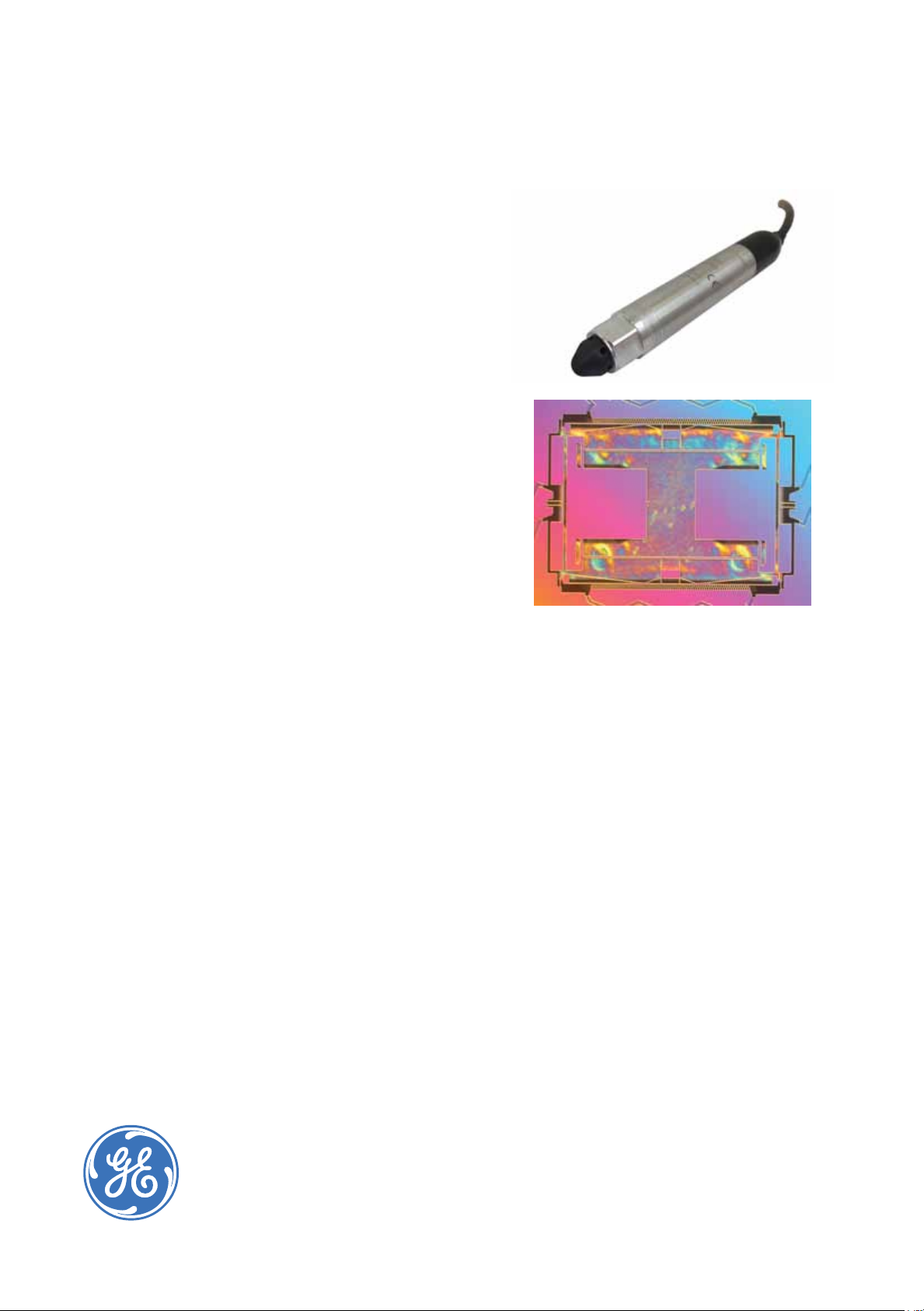
RPS/DPS
8200/8300
High Accuracy Resonant
Pressure Sensor for
Harsh Media
For over 40 years, Druck has manufactured
precision pressure sensors with a capability to
meet critical applications in industrial, aerospace,
oil and gas, and research environments. Today,
Druck is part of GE Measurement & Control and
has continually worked to develop and improve on
the performance of our pressure sensors to meet
customer’s requirements.
The RPS/DPS 8200/8300 moves the exciting new
TERPS technology into harsh media environments.
TERPS is a resonant silicon pressure sensor
technology platform that provides an order of
magnitude greater accuracy and stability than
current pressure measurement technologies
available. The new TERPS technology also extends
the pressure range capability to high pressures
and by incorporating true pressure media isolation
greatly improves its suitability for use in harsh
environments.
By packaging TERPS technology in Hastelloy C276,
the RPS/DPS 8200/8300 allows for use in harsh
corrosive media such as sea water, or sour gas.
The combination of the power of the TERPS
technology and the quality, reliability and exibility
of the RPS/DPS 8000 Series oer a truly unique
solution for high accuracy and high stability
pressure measurement requirements.
Features:
• High Precision, ±0.01% FS over compensated
temperature range
• High Stability, ±100 ppm FS/year
• Wide temperature range, -40°C to +125°C (-40°F
to 257°F)
• Media isolated construction, suitable for use in
harsh environments
• Multiple Output congurations, RS-232, RS-485,
Frequency & Diode (TTL)
• Selection of pressure & electrical connections to
suit specic requirements
GE imagination at work
Page 2

Specications
Measurement
Performance
There are two levels of performance specication:
standard and Improved.
Pressure Ranges
• 0 to 2 bar (0 to 30 psi) absolute
• 0 to 7 bar (0 to 100 psi) absolute
• 0 to 14 bar (0 to 200 psi) absolute
• 0 to 20 bar (0 to 300 psi) absolute
• 0 to 35 bar (0 to 500 psi) absolute
• 0 to 70 bar (0 to 1000 psi) absolute
(Values in psi are approximate.)
The lowest calibrated pressure is 35 mbar absolute.
Overpressure
1.5X FS
Sensor Failure Pressure
2.0X FS
Pressure Containment
• Ranges to 7 bar, (100 psi), 70 bar (1,000 psi)
• Ranges to 70 bar (1,000 psi), 200 bar (3,000 psi)
Supply and Output
Electronics
Option
0 6 to 28 Frequency^ &
1 6 to 28 Frequency^ &
A 11 to 28 RS485 16.5 quiescent , 32 max
B 11 to 28 RS232 16.5 quiescent , 32 max
* Low Power has Jitter of <120 ns
** Low Noise has Jitter of <75 ns
*** At 25°C (77°F)
^ Square wave pressure signal, 25 kHz nominal, 4-10 kHz span
^^ Forward voltage diode, 0.5 to 0.7 V @ 25°C (77°F), typically –2
mV/°C nominal
Supply
Voltage (V)
Output Current Consumption***
(mA)
3.5
Diode^^ (Low
Power)*
10
Diode^^ (Low
Noise)**
Specications include combined eects of non-linearity,
hysteresis, repeatability and temperature errors over the
compensated temperature range, and over the pressure
range 35 mbar to the full scale pressure.
Accuracy Code Precision
A1- Standard 0.02% FS
A2- Improved 0.01% FS
.
For Frequency & Diode output the above accuracies are
achievable by using a polynomial curve t algorithm and
coecient data supplied with sensor.
Sensors are calibrated against standards traceable to
UKAS operating to better than 100 ppm.
Compensated Temperature Ranges:
There are three compensated temperature ranges
available:
-10 to +50°C
-40 to +85°C
-40 to +125°C
Temperature Eects
All temperature eects are included in the accuracy
statement.
Long Term Stability
Standard: ±0.02% FS/annum
Improved: ±0.01% FS/annum
Note: Unless otherwise specied, specications are at reference
conditions: 25°C (77°F) ±5°C (±9°F)
.
Orientation (g) Sensitivity
Less than 0.2 mbar/g
Response Time
< 300 msec for pressure change from 10% to 90% FS
Supply Response
Frequency & Diode: Accurate to specication within 500
ms of supply switch on, over all operating temperatures
RS 232/485: First stable reading within 20 sec of supply
switch on
Electrical Protection
Connecting V
of pins on the connector will not damage the unit
and GND between any combinations
supply
Insulation
500 V dc
Physical Specications
Storage Temperature Range
As operating temperature range.
Operating Temperature Range
See electrical connector section
Pressure Media
Media compatible with Hastelloy C276
Ingress Protection
See Electrical Connector Section
Page 3

Vibration
DO-160E Curve W Sine sweeps 5 Hz to 2 kHz, levels to
20g
n
<0.2 mbar/gn (<0.003 psi/gn) output change
Shock
DO-160E 9 (Figure 7.2) 20 gn 11 ms terminal saw-tooth
prole
Negligible calibration change
Humidity
MIL-STD-810D Method 507.2 Procedure III (Aggravated
humidity environment, 65°C, 95% RH)
Pressure Connector
Available Options are
• G1/4 Female
• G1/4 Male Flat
• 1/4 NPT Female
• 1/4 NPT Male
• Depth Cone (G1/4 Female)
Please ensure that only the intended sealing face is
used when mounting the sensor. Failure to comply with
this requirement may aect performance or calibration
accuracy.
Connection Details
Option Code Connection Function
Frequency
& Diode
Flying
Leads
CABLE 3, 4, RED SUPPLY +VE SUPPLY
0 RED SUPPLY +VE SUPPLY
YELLOW FREQ RS485 B Rx
GREEN +VE TEMP RS485 A Tx
BLUE GROUND GROUND GROUND
ORANGE EEPROM - -
BLACK -VE TEMP - -
YELLOW FREQ RS485 B Rx
BLUE +VE TEMP RS485 A Tx
WHITE GROUND GROUND GROUND
ORANGE EEPROM - -
BLACK -VE TEMP - -
SCREEN - - -
-
DigitalRS485
+VE
+VE
Digital RS232
SUPPLY +VE
SUPPLY +VE
Male threaded pressure connectors must not be sealed
or constrained against the face at the base of the thread.
The forward cone or at face should always be used, as
indicated below.
Electrical Connector
Code
Number
0 No Connector -55 to +125 -67 to +257 -
3 Polyurethane Depth -40 to +80 -40 to +176 68
4 Hytrel Depth -40 to +80 -40 to +176 68
Certication
• CE Marked
• RoHS
• EMC Standards
BS EN 61000-6-1: 2007 Susceptibility - Light Industrial
BS EN 61000-6-2: 2005 Susceptibility - Heavy Industrial
BS EN 61000-6-3: 2007 Emissions - Light Industrial
BS EN 61000-6-4: 2007 Emissions - Heavy Industrial
BS EN 61326-1: 2006 Electrical Equipment for
Measurement, Control and Laboratory Use - EMC
requirements
BS EN 61326-2-3:2006 Requirements for pressure
transducers
Description Max Operating temp range
°C °F
IP
rating
Mechanical Drawings
MEDIUM PRESSURE
CONSTRUCTION
60
(2.36)
81
(3.18)
RPS800
PRESSU #### 8000
S/N *******
*** TO *** ba
Supply: *** T
Output: *** T
Temp. Range: DRUCK LTD. GR
Ø
(0.98)
25
8
(0.31)
14.5
(0.57)
Ø
25
(0.98)
DEPTH CABLE
16
(0.62)
DEPTH CONE
PRESSURE ADAPTOR
Notes:
1. All dimensions are nominal lengths and are subject to
change.
2. All dimensions are in millimeters (inches).
3. Other pressure and electrical connectors may be
available, please contact GE.
Page 4

(1) Select model number
Main Product Variant
RPS Resonant Pressure Sensor - Frequency & Diode Output (Note 1)
DPS Digital Pressure Sensor - Digital Output (Notes 1 and 2)
Product Series
8 RPS/DPS 8000 Series
Diameter, Material and Isolation
2 25mm Oil isolated Hastelloy Wetted Parts
3 25 mm Oil isolated all Hastelloy
Electrical Connector
0 No Electrical Connector (Flying leads)
3 Polyurethane Cable (Depth) IP68 (Note 2)
4 Hytrel Cable (Depth) IP68 (Note 2)
Output Option
0 Frequency & Diode (Low Power <3.5 mA)
1 Frequency & Diode (Low Jitter aprox 75 ns)
A RS485 (Note 2)
B RS232 (Note 2)
Compensated Temperature Range
TA -10 to +50 °C
TB -40 to +85 °C
TC -40 to +125 °C
Accuracy
A1 - Standard 0.02%
A2 - Improved 0.01%
Calibration
CC Full Thermal Calibration
Hazardous Area Approval
H0 None
Pressure Connector
PA G1/4 Female
PB G1/4 Male Flat
PE 1/4 NPT Female
PF 1/4 NPT Male
PW Depth Cone (G1/4 Female)
R 8 2 4 1 - TA - A2 - CC - H0 - PA Typical Model Number
Note 1: RPS variants require Output Option Code ‘0’ or ‘1’. DPS variants require Output Option Code ‘A’ or ‘B’.
Note 2: Compensated temperature range -40 to +125°C (TC) is not available with this option.
2) State pressure range (2, 7, 14, 20, 35 or 70 bar or equivalents) and units: e.g., 0 to 20 bar, 0 to 100 psi
Unit options are:
Symbol Description
bar bar
mbar millibar
psi pounds/sq. inch
Pa Pascal
hPa hectoPascal
kPa kiloPascal
MPa megaPascal
mmH
cmH
mH
inH
ftH
mmHg mm mercury
inHg inches mercury
kgf/cm
atm atmosphere
Torr torr
O mm water
2
O cm water
2
O metres water
2
O inches water
2
O feet water
2
2
kg force/sq. cm
3) State cable lengths and units: e.g. 1 m cable, 3 ft cable (only required on certain electrical connectors)
Typical order examples:
RPS 8301-TC-A2-CC-H0-PA,70 bara
DPS 823A-TA-A1-CC-H0-PW, 2 bara, 10 m cable
www.ge-mcs.com
920-602A
© 2013 General Electric Company. All Rights Reserved. Specications are subject to change without notice. GE is a registered trademark of General Electric Company. Other company or product
names mentioned in this document may be trademarks or registered trademarks of their respective companies, which are not aliated with GE.
 Loading...