

Page 1
GE
Oil & Gas
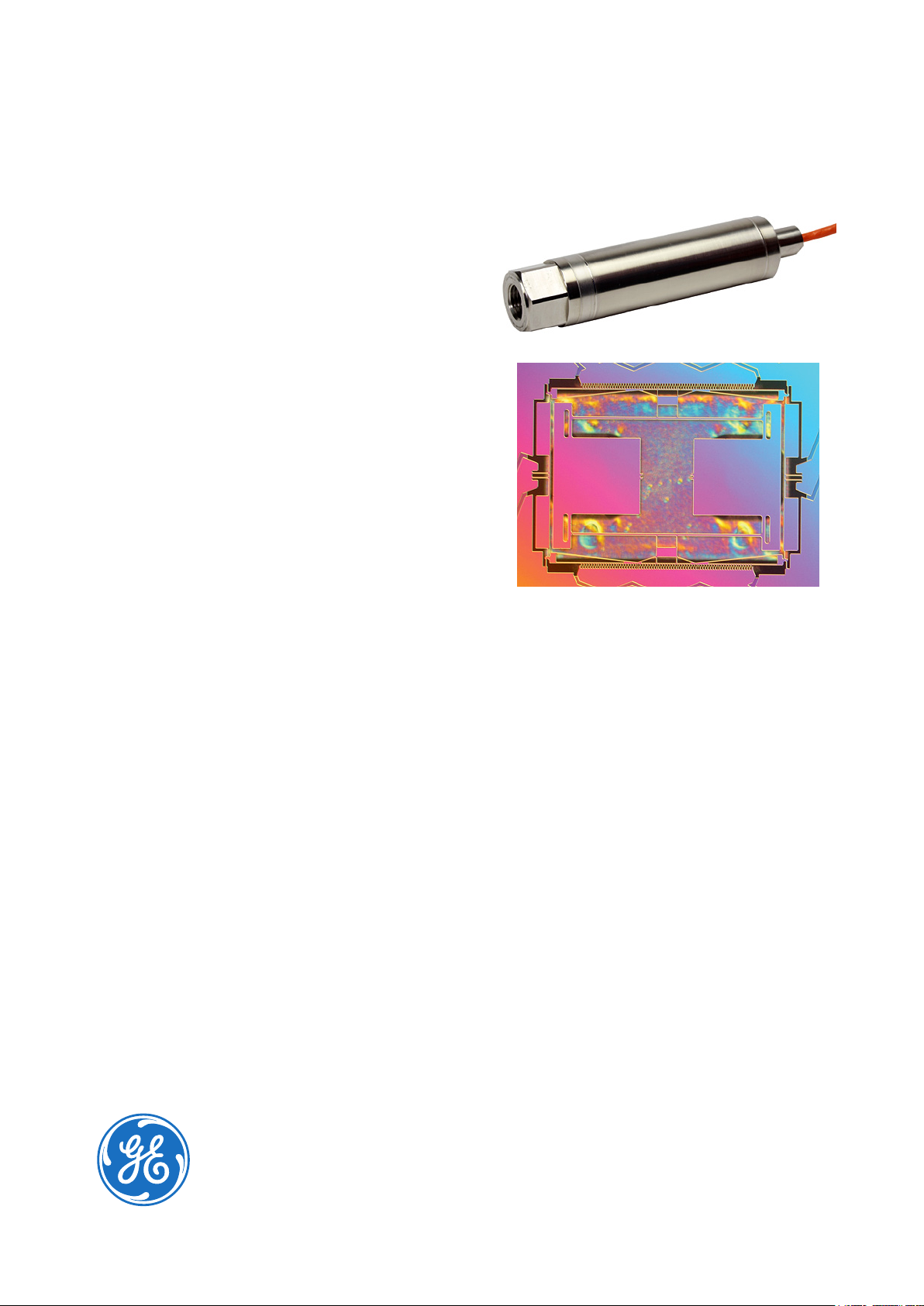
RPS/DPS 8100
High Accuracy Resonant
Pressure Sensor
Since 1972, Druck has manufactured precision
pressure sensors with a capability to meet critical
applications in industrial, aerospace, oil and gas,
and research environments. Today, Druck is
part of GE Oil & Gas and has continually worked
to develop and improve on the performance of
our pressure sensors to meet our customers’
requirements.
The RPS/DPS 8100 incorporates the exciting new
TERPS technology. TERPS is a resonant silicon
pressure sensor technology platform that provides
an order of magnitude greater accuracy and
stability than current pressure measurement
technologies.
In addition to providing the performance and
packaging improvements available with TERPS,
the RPS/DPS 8100 product line takes advantage
of best practices to oer a wide range of pressure
and electrical connections to enable a level of
customization for your specic requirements never
before available in the performance class of this
sensor.
The combination of the power of the TERPS
technology and the quality, reliability and exibility
of the RPS/DPS 8100 Series oers a truly unique
solution for high accuracy and high stability
pressure measurement requirements.
Features:
• High Precision, ±0.01% FS over compensated
temperature range
• High Stability, ±50 ppm FS/year (typical)
• Wide temperature range, up to -55 to +125°C
(-67 to 257°F)
• Multiple Output congurations, RS232, RS485,
USB 2.0, CAN Bus, Frequency & Diode (TTL)
• Wide selection of pressure & electrical
connections to suit specic requirements
• Low acceleration eects
Page 2

Specications
Measurement
Base Pressure Ranges
• 0 to 2 bar (0 to 30 psi) absolute
• 0 to 3.5 bar (0 to 50 psi) absolute
Calibrated Ranges
• Barometric: Up to 1.3 bar (18 psi) with minimum span
of 350 mbar (5 psi)
• Low pressure: Up to 2 bar (30 psi) with minimum span
of 0.5 bar (7 psi)
• High pressure: Up to 3.5 bar (50 psi) with minimum
span of 1 bar (14 psi)
Note: Values in psi are approximate.
Alternative barometric ranges are available on request.
Higher pressure ranges are available in the
RPS/DPS 8000 series.
Overpressure
2X FS
Pressure Containment
7 bar (100 psi)
Supply and Output
Electronics
Option
1 5 to 32 Frequency2 &
A 9 to 28 RS485 16.5 quiescent, 32 max
B 9 to 28 RS232 16.5 quiescent, 32 max
C 7.5 to 30 CAN Bus 25 quiescent, 32 max
U 4.8 to 5.2 USB 2.0 40 quiescent, 100 max
(1) Full temparature range
(2) Square wave pressure signal, 25 kHz nominal, 3-9 kHz span
(3) Voltage 0.4 to 0.8 V @ 25°C (77°F), typically –2 mV/°C
Supply
Voltage
(Vdc)
Output Current Consumption1
(mA)
<3.5
Diode3 (TLL)
Electrical Protection
RS232/485/CAN Bus/TTL: Connecting V
between any combinations of pins on the connector will
not damage the unit
USB: Complies with USB 2.0 peripheral specication.
supply
and GND
Insulation
RS232/485/CAN Bus/TTL:
>100 Mohm @ 500 Vdc between all pins and case.
Performance
There are two levels of performance specication:
Standard and Improved
Specications include combined eects of non-linearity,
hysteresis, repeatability and temperature errors over
the compensated temperature range and calibrated
pressure range.
Accuracy Code Precision
A1- Standard 0.02% FS
A2- Improved 0.01% FS
• For barometric ranges with improved accuracy,
precision is ±0.1 hPa max.
• For Frequency & Diode output the above accuracies
are achievable by using a polynomial curve t
algorithm and coecient data supplied with sensor.
• Sensors are calibrated against standards traceable to
UKAS operating to better than 100 ppm.
Compensated Temperature Ranges:
There are four compensated temperature ranges
available:
• -10 to +50°C
• -40 to +85°C
• -40 to +125°C (TTL and CAN bus only)
• -55 to +125°C (TTL and CAN bus only)
Response Time
• TTL Output:
<25 ms for pressure change from 10% to 90% FS
• RS232/485/USB Output:
Dependent on the output update rate which is set by
the user with a minimum of 500 ms
(see manual K0473 for details)
• CAN Bus:
Dependent on the output update rate which is set by
the user with a minimum of 10 ms while maintaining
specication (see manual K0533 for details)
Supply Response
• TTL : Accurate to specication within
500 ms of supply switch on, overall operating
temperatures
• CAN Bus/RS232/485/USB: Accurate to specication
within 10 minutes of turning supply switch on
Temperature Eects
All temperature eects are included in the accuracy
statement.
Long Term Stability
Standard: ±0.02% FS/annum max.
Improved: ±0.01% FS/annum max. (±0.005% FS typical)
Note: Unless otherwise specied, specications are at the
reference conditions of 25°C (77°F) ±5°C (±9°F)
Orientation (g) Sensitivity
Less than 0.05 mbar/g
Page 3
Physical Specications
Storage Temperature Range
As compensated temperature range
Operating Temperature Range
As compensated temperature range
(Restricted by some electrical connector options)
Pressure Media
Non-condensing dry gases compatible with 316L
Stainless Steel, silicon, silicon dioxide, Fluorosilicon RV
adhesive and glass
Ingress Protection
See Electrical Connector section
Vibration
• BS EN 60068-2-6 (2008) Sine sweeps 5 Hz to 2 kHz,
levels to 20g
n
• BS EN 60068-2-64 random 10 Hz to 2kHz to 4gn RMS
for 1 hour each axis
• Less than 0.02% FS eect at any time
Shock
• DO-160E 9 (Figure 7.2) 20 gn 11 ms terminal
saw-tooth prole
• Negligible calibration change
Pressure Connector
Pressure connector should be one of:
• G1/4 Female
• G1/4 Male Flat
• G1/4 Male 60° Internal Cone
• G1/8 Male 60° Internal Cone
• 1/4 NPT Female
• 1/4 NPT Male
• 1/8 NPT Male
• M20 x 1.5 Male (3mm bore)
• M14 x 1.5 60° Internal Cone
• M12 x 1 Internal Cone
• 7/16-20 UNJF Male 74° External Cone
• G1/2 Male
• G1/4 Quick Connect
• 1/2 NPT Male
• G1/4 Male Flat Long
• 7/16-20 UNF Female
• Depth Cone (G1/4 Female)
• 7/16-20 UNF Male Short Flat
• 3/8-24 UNJF
• 1/4 VCR Female
• 1/4 VCR Male
• Other pressure connectors may be available.
Contact GE to discuss your requirement.
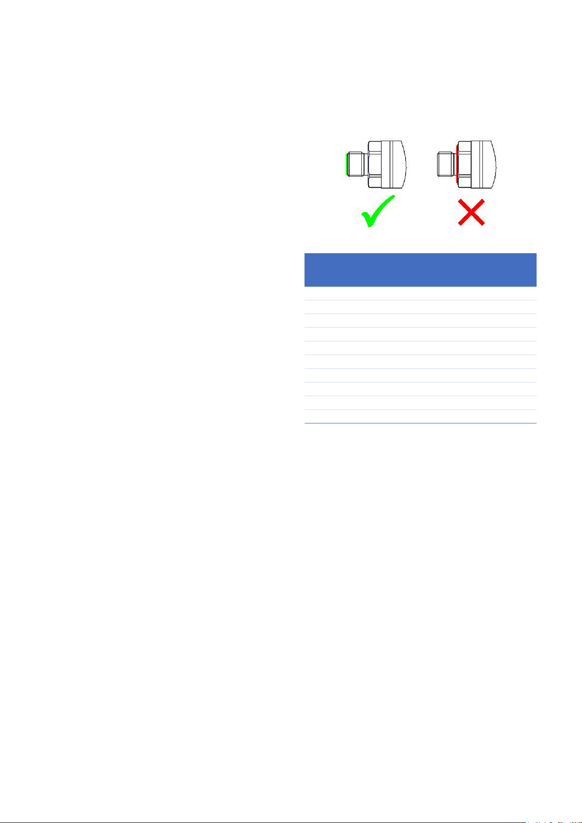
Please ensure that only the intended sealing face is
used when mounting the sensor. Failure to comply with
this requirement may aect performance or calibration
accuracy.
Male threaded pressure connectors must not be sealed
or constrained against the face at the base of the
thread. The forward cone or at face should always be
used, as indicated below.
Electrical Connector
Code
Description Max Operating
No.
0 No Connector -55 to +125 -67 to +257 -
1 Polyurethane Cable -40 to +85 -40 to +176 65
2 Raychem Cable -55 to +125 -67 to +257 65
3 Polyurethane Depth -40 to +85 -40 to +176 68
4 Hytrel Depth -40 to +85 -40 to +176 68
6 MIL-C-26482 -55 to +125 -67 to +257 *
C 1/2 NPT Conduit -40 to +85 -40 to +176 67
G M12 X 1, 5-pin -55 to +125 -67 to +267 *
H PTFE Cable (Orange) -55 to +125 -67 to +267 54
M Micro-USB Socket -40 to +85 -40 to +176 -
Temp. Range
°C °F
IP
Rating
* Hermetically sealed connectors with a maximum
leak rate of 1 x 10
-6
cc/s at 1 atmosphere. High IP rated
mating connectors are available.
Certications
• CE Marked
• RoHS
• EMC Standards:
- BS EN 61000-6-1: 2007, Susceptibility Light Industrial
- BS EN 61000-6-2: 2005, Susceptibility Heavy Industrial
- BS EN 61000-6-3: 2007+A1:2011, Emissions -
Light Industrial
- BS EN 61000-6-4: 2007+A1:2011, Emissions -
Heavy Industrial
- BS EN 61326-1: 2013, Electrical Equipment for -
Measurement, Control and Laboratory Use EMC requirements
- BS EN 61326-2-3:2013 Requirements for pressure
transducers
Page 4

Connection Details
Option Code Connection Function
Frequency
& Diode
Flying Leads 0 RED SUPPLY +VE SUPPLY +VE SUPPLY +VE SUPPLY +VE
YELLOW FREQ RS485 B Rx CAN Hi
GREEN +VE TEMP RS485 A Tx CAN Lo
BLUE GROUND GROUND GROUND SUPPLY -VE
BLACK -VE TEMP - - CAN 0V
ORANGE EEPROM - - -
Option Code Connection Function
Frequency
& Diode
CABLE 1, 3, 4, C RED SUPPLY +VE SUPPLY +VE SUPPLY +VE SUPPLY +VE
YELLOW FREQ RS485 B Rx CAN Hi
BLUE +VE TEMP RS485 A Tx CAN Lo
WHITE GROUND GROUND GROUND SUPPLY -VE
BLACK -VE TEMP - - CAN 0V
ORANGE EEPROM - - -
SCREEN - - - -
DigitalRS485
DigitalRS485
Digital RS232
Digital RS232
Digital CAN Bus
Digital CAN Bus
Option Code Connection Function
Frequency
& Diode
M12 G 1 SUPPLY +VE SUPPLY +VE SUPPLY +VE N/C
2 FREQ RS485 B Rx SUPPLY +VE
3 GROUND GROUND GROUND SUPPLY -VE
4 +VE TEMP RS485 A Tx CAN HI
5 EEPROM - - CAN LO
Option Code Connection Function
Frequency
& Diode
PTFE H RED SUPPLY +VE SUPPLY +VE SUPPLY +VE SUPPLY +VE
YELLOW FREQ RS485 B Rx CAN Hi
GREEN +VE TEMP RS485 A Tx CAN Lo
BLUE GROUND GROUND GROUND SUPPLY -VE
BLACK EEPROM
WHITE -VE TEMP
SCREEN CASE CASE CASE CASE
DigitalRS485
DigitalRS485
Digital RS232
Digital RS232
- - -
- -
Digital CAN Bus
/CAN 0V
Digital CAN Bus
CAN 0V
Option Code Connection Function
Frequency
& Diode
RAYCHEM 2 RED SUPPLY +VE SUPPLY +VE SUPPLY +VE SUPPLY +VE
WHITE FREQ RS485 B Rx CAN Hi
GREEN +VE TEMP RS485 A Tx CAN Lo
BLUE GROUND GROUND GROUND SUPPLY -VE
BLACK EEPROM - - -
SCREEN - - - -
Option Code Connection Function
Frequency
& Diode
MIL-C 6 A SUPPLY +VE SUPPLY +VE SUPPLY +VE SUPPLY +VE
B FREQ RS485 B Rx CAN Hi
C +VE TEMP RS485 A Tx CAN Lo
D GROUND GROUND GROUND SUPPLY -VE
E EEPROM - - -
F -VE TEMP - - CAN 0V
DigitalRS485
DigitalRS485
Digital RS232
Digital RS232
Digital CAN Bus
/CAN 0V
Digital CAN Bus
Option Code Connection Function
Frequency
& Diode
Micro-USB M 1 - - +5 V -
2 - - D-VE
3 - - D+VE
4 - - ID
5 - - GROUND
Maximum
Cable length
(m)
Frequency &
Diode
10 10 1000 1000 2
DigitalRS232
DigitalRS485
Digital RS485
Digital RS232
CAN Bus USB*
Note*1: Cable not provided with USB option.
Digital CAN Bus
1
Page 5

Dimensional Drawings
8 (0.31)
MALE PRESSURE CONNECTION
22 A/F
(0.86)
14.5
(0.57)
FEMALE PRESSURE CONNECTION
16
(0.62)
DEPTH CONE
PRESSURE ADAPTOR
25 TYP
(0.98)
Ø
25 (0.98)
MEDIUM PRESSURE CONSTRUCTION
25.5 (1.00)
Ø 25
(0.98)
MICRO-USB SOCKET
42 (1.65)
32
(1.25)
CONDUIT WITH POLYURETHANE CABLE
22 A/F
(0.86)
5 (0.20)
25 (0.98)Ø
FLYING LEADS
15.5 (0.61)
78 (3.07)
4 (0.16) 24 (0.94) TYP
RPS800
PRESSU #### 8000
S/N *******
*** TO *** ba
Supply: *** T
Output: *** T
Temp. Range: DRUCK LTD. GR
25
Ø 25 (0.98)
(0.98)
Ø
7 (0.27)
Ø
(0.98)
Ø
(0.98)
25
7 (0.27)
25
CRIMP & BOOT PU CABLE IP65
21 TYP
(0.82)
RAYCHEM CABLE
60 (2.36)
DEPTH CABLE
15 TYP (0.53)
24 AWG 7/0.2 PTFE CABLE
17
(0.66)
22 A/F
(0.86)
25
Ø
(0.98)
BAYONET MIL-C-26482
OPTIONAL WELDED
PRESSURE ADAPTOR
25 (0.98)Ø
M12x1 5-PIN
Notes:
1. All dimensions are nominal lengths and are subject to change.
2. All dimensions are in millimeters (inches).
3. Other pressure and electrical connectors may be available. Please contact GE.
Page 6

Ordering Information
(1) Select model code
Main Product Variant
RPS Resonant Pressure Sensor - Frequency & Diode Output (Note 1)
DPS Digital Pressure Sensor - Digital Output (Note 1)
Product Series
8 RPS/DPS 8100 Series
Diameter, Material and Isolation
1 25mm Stainless Steel Silicon Exposed
Electrical Connector
0 No Electrical Connector (Flying leads)
1 Polyurethane Cable
2 Raychem Cable
3 Polyurethane Cable (Depth)
4 Hytrel Cable (Depth)
6 MIL-C-26482 (6-pin Shell Size 10)
C 1/2” NPT Conduit with Polyurethane Cable
G M12x1, 5-Pin
H PTFE Cable
M Micro-USB Socket (Note 3)
Output Option (Note 5)
1 Frequency & Diode
A RS485
B RS232
C CAN Bus
U USB 2.0 (Note 4)
Compensated Temperature Range
TA -10 to +50°C
TB -40 to +85°C
TC -40 to +125°C (Note 2)
TD -55 to +125°C (Note 2)
Accuracy
A1 Standard: 0.02%
A2 Improved: 0.01%
Calibration
CC Full Thermal Calibration
Hazardous Area Approval
H0 None
Pressure Connector
PA: G1/4 Female
PB: G1/4 Male Flat
PC: G1/4 Male 60 degree internal Cone
PD: G1/8 Male 60 degree internal Cone
PE: 1/4 NPT Female
PF: 1/4 NPT Male
PG: 1/8 NPT Male
PH: M20x1.5 Male (3mm bore)
PJ : M14x1.5 60° Internal Cone
PK: M12x1 Internal Cone
PL: 7/16-20 UNJF Male 74 degree external cone
PN: G1/2 Male
PQ: G1/4 Quick Connect
PR: 1/2 NPT Male
PT: G1/4 Male Flat Long
PV: 7/16-20 UNF Female
PW: Depth Cone (G1/4 Female)
PX: 7/16-20 UNF Male Short Flat
PY: PY: 3/8-24 UNJF
RA: 1/4 VCR Female
RF: 1/4 VCR Male
RPS 8 1 4 1 - TA - A2 - CC - H0 - PA [Typical Model Code]
Note 1: RPS variants require Output Option Code ‘1’. DPS variants require Output Option Code ‘A’ , ‘B’, ‘C’ or ‘U’.
Note 2: Not available for RS232/485/USB outputs or micro USB socket connector.
Note 3: Only available with USB output option.
Note 4: Only available with micro USB socket connector.
Page 7

Ordering Information (cont.)
2) State pressure range and units (e.g., 0 to 1.6 bar, 0 to 20 psi):
Unit options are:
Symbol Description
bar bar
mbar millibar
psi pounds/sq. inch
Pa Pascal
hPa hectoPascal
kPa kiloPascal
MPa megaPascal
mmH2O mm water
cmH2O cm water
mH2O metres water
inH2O inches water
ftH2O feet water
mmHg mm mercury
inHg inches mercury
kgf/cm2 kg force/sq. cm
atm atmosphere
Torr torr
3) State cable lengths and units (e.g., 1 m cable, 3 ft cable) (only required on certain electrical connectors):
NOTE 5: Maximum Cable length: (1) Frequency & Diode - 10 m, (A) RS485 - 1000 m, (B) RS232 - 10 m, (C) CAN Bus - 1000 m.
Integer values only, e.g. 1m (3 ft) cable. Minimum cable length is 1m (3 ft) if cable is supplied.
Typical order examples:
RPS 8111-TA-A1-CC-H0-PA, 3.5 bara, 5 m cable
DPS 816A-TB-A2-CC-H0-PL, 750-1,150 mbara
Page 8

www.gemeasurement.com
920-565G
© 2016 General Electric Company. All Rights Reserved. Specications are subject to change without notice. GE is a registered trademark of General Electric Company. Other company or product
names mentioned in this document may be trademarks or registered trademarks of their respective companies, which are not aliated with GE.
 Loading...