

Page 1
GE
Sensing & Inspection Technologies
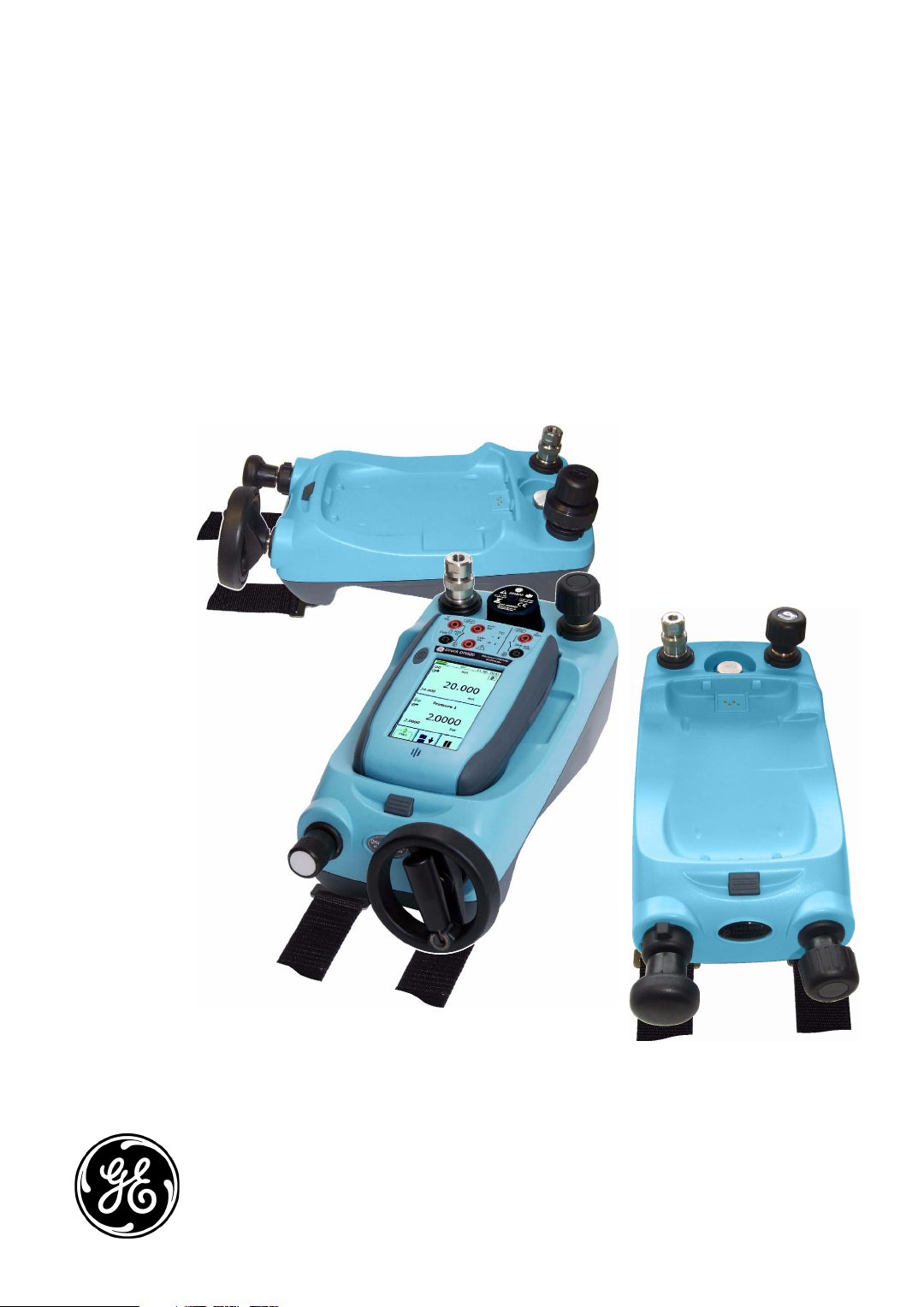
Druck PV 62x
pneumatic/hydraulic pressure stations
user manual - K0457
Page 2
Issue 1
Quick reference data
A1.1
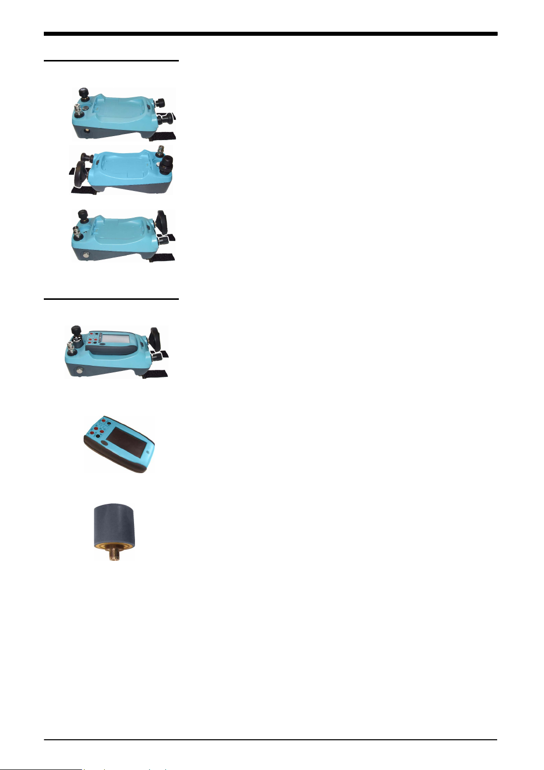
PV 621: Pneumatic pressure station
-950 mbar to 20 bar (-13.5 to 300 psi)
PV 622: Pneumatic pressure station
-950 mbar to 100 bar (-13.5 to 1500 psi)
PV 623: Hydraulic pressure station
0 to 1000 bar (0 to 15000 psi)
A1.2
PV 62x + DPI 620 + PM 620
Recommended pressure modules (PM 620) *
PV 621 models 25 mbar to 20 bar (0.36 to 300 psi)
PV 622 models 25 mbar to 100 bar (0.36 to 1500 psi)
PV 623 models 70 to 1000 bar (1000 to 15000 psi)
*Caution: To prevent damage to the PM 620 module, only use it
within the specified pressure limit on the label.
A1.3
PV 62x pressure relief valves (PR V )
(Recommended options)
Parts: IO620-PRV-P1 to P5 (Pneumati c)
PV 621 models 1 to 30 bar (14.5 to 435 psi)
PV 622 models 1 to 100 bar (14.5 to 1500 psi)
Parts: IO620-PRV-H1 to H5 (Hydraulic)
PV 623 models 50 to 1000 bar (725 to 15000 psi)
Copyright © 2008 General Electric Company. All rights reserved.
Trademarks All product names are trademarks of their respective
companies.
ii
Page 3
Issue 1
Safety
General warnings
Pressure warnings
Before you use the instrument, make sure that you read and
understand all the related data. This includes: the applicabl e
local safety procedures, th is publication, and the instructions
for the accessories/options/ equipment you are using it with.
WARNING
• It is dangerous to ignore the specified limits for the
instrument or to use the instrument when it is not in its
normal condition. Use the applicable protection and
obey all safety precautions.
• Do not use the instrument in locations with explosive
gas, vapour or dust. There is a risk of an explosion.
• It is dangerous to attach an external sour ce of pressure
to a PV 62x series pressure st ation. Use only the
internal mechanisms to set and control the pressure in
the pressure station.
• Some liquid and gas mixtures are dangerous. This
includes mixtures that occur be cause of con t amination.
Make sure that the equipment is safe to use with the
necessary media.
Electrical warnings
• Pressurized gases and fluids are dangerous. Bef ore you
attach or disconnect pressure equipment, safely r elease
all the pressure.
• To prevent a dangerous release of pressure, make sure
that all the related pipes, hoses and equipment have the
correct pressure rating, are safe to use and are
correctly attached.
If you use the DPI 620 calibrator with your pressure station,
these warnings are also applicable:
• To prevent electrical shocks or damage to the DPI 620
calibrator, do not connect more than 30V between the
terminals, or between the terminals and the ground
(earth).
• This instrument uses a Lithium-Polymer (Li-Polymer)
battery pack. To prevent an ex plosion or fire, do not
short circuit, do not disassemble, keep it safe from
damage.
Continued
[EN] English - K0457 Safety iii
Page 4
Issue 1
1
1 1
• To prevent an explosion or fire, use only the GE
specified battery, power supply and battery charger .
• To make sure the display shows the correct data,
disconnect the test leads before you set the power to on
or change to another measure or source function.
Cautions
To prevent damage to the instrument, do not let dirt get
into the pressure mechanism. Before you attach
equipment, make sure it is clean.
To prevent damage to t he instrument wh en you move it,
hold the body of the pressure station or use the carry
strap (or specified accessories).
PV 621/PV 622 models only. Before you turn the
pressure/vacuum selector to + or -, release all the
pressure. Sudden high pressure in the pump
mechanism can cause damage.
PV 623 models only. Ice in the pressur e mechanism can
cause damage. If the temperature is less than 4°C
(39°F), drain all water from the instrument.
In its normal condition, the PV 623 model contains
hydraulic fluid. To make sure it does not spill out, seal
the system and put it on its side before you install a
PRV.
To prevent damage to the PM 620 module, only use it
within the specified pressure limit on the label.
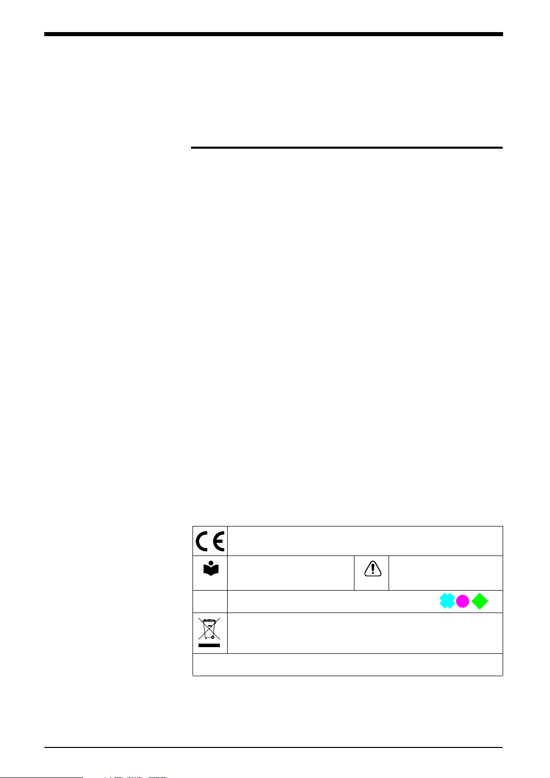
Marks and symbols
on the instrument
Before you start an operation or procedure in this publication,
make sure that you have the necessary ski lls (if necessary, with
qualifications from an approved training est abl is hment) . Follow
good engineering practice at all times.
Complies with European Union directives
Read the manual Warning - refer to the
manual
PRV Pressure relief valve (Refer to Chapter 1; item )
Do not dispose of this product as household waste. Refer to
Chapter 6 (Maintenance procedures).
More marks and symbols are specified in this manual
iv Safety K0457 - [EN] English
Page 5
Issue 1
PV 622
PV 621
PV 623
Pressure calibrator
DPI 620
PM 620
Overview
Other module options
There are three pressure stations in the PV 62x series:
• two pneumatic pressure stations to give you accurate and
controlled pressure and vacuum conditions:
PV 621: -950 mbar to 20 bar (-13.5 to 300 psi) version
PV 622: -950 mbar to 100 bar (-13.5 to 1500 psi) version
• one hydraulic pressure station to give you accurate and
controlled hydraulic pressure conditions:
PV 623: 0 to 1000 bar (15000 psi)
To give the attached equipment overpressure protection, there
are pressure relief valves (PRV) available for all the pressure
stations; refer to Secti on 1.5 (Ac cessories).
The pressure stations are part of a set of hand-held modules
that you can quickly put together to include a wide range of
calibrator functions.
Pressure calibrator (this user manual): You can use the
pressure stations on their own or you can attach the DPI 620
calibrator and a PM 620 module to make a fully integrated
pressure calibrator instrument.
Advanced modular calibrator, DPI 620 (user manual K0449): Optional item. This is a bat tery-powered ins trument for
electrical measure and source operations and HART®
communications. It also supplies the power and user interface
functions for all the add-on modules. You can use the
touch-screen to display up to six different parameters.
Pressure modules, PM 620 (this user manual): Optional
item. These modules attach to a pressure station (PV 62x) to
give the DPI 620 calibrator the necessary pressure
measurement functionality. They are fully interchangeable
“plug and play” modules with no initial set-up or user
calibration.
Software (user manual - K0449): The DPI 620 calibrator
includes the following sof tware:
• documenting software • HART® communications
software
Other accessories and options: For part numbers (P/N),
refer to Section 1.5 (Accessories).
[EN] English - K0457 Overview v
Page 6
Issue 1
PV 622
PV 621
PV 623
Pressure calibrator
Summary of functions
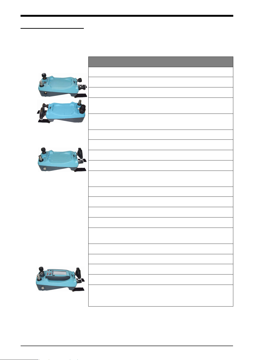
This table gives a summary of the available funct ions with the
PV 62x pressure stations.
PV 62x - pressure station functions
Function
Pneumatic pressure stations
*
PV 621: Pressure from vacuum (95%) to 20 bar (300 psi);
* PV 622: Pressure from vacuum (95%) to 100 bar (1500 psi)
Selector switch to change the pump operation from pressure
generator to vacuum generator
Needle point pressure release valve to control the release of
pressure.
Hydraulic pressure station
* PV 623: Hydraulic pressure from 0 to 1000 bar (15000 psi)
3
Internal hydraulic reservoir: 100 cm
Self sealing pressure module connection to prevent fluid leaks.
(6.1 in3)
Fast thermal stability for devices attached directly to the pressure
test connection (≤ one minute)
All pressure stations
“Quick fit” pressure adaptors for the device under test
** Pressure connecti on for a PM 620 mod ule
Volume adjuster to give accurate control of pressure conditions.
Latch mechanism to attach the DPI 620 calibrator to make a fully
integrated pressure calibrator instrument
** Pressure relief valves (PRV) to give overpressure protection.
** Pressure station + DPI 620 calibrator + PM 620 module
Measure pressure/Leak test
Documenting software
®
HART
communications software to set up and calibrate devices that use
the HART
* Refer to Chapter 7 (Specification)
** Optional item
(Highway Addressable Remote Transducer)
®
field communications protocol.
vi Summary of functions K0457 - [EN] English
Page 7

Issue 1
1
1 1
About this manual
This user manual is set up for you to use on a computer or
similar device that has the necessary software to read a
Portable Document Format (PDF) file.
It is supplied as a PDF on a compact disc (CD) but you can
copy or save the PDF onto a computer or similar device that
has the necessary PDF software.
To navigate between related items of information, the use r
manual includes cross references and links; for example:
• text cross references: ... Figure 1-1; Table 1-1; Chapter 1;
Section 1.5 (Accessories)
• some (but not all) symbols:
Note: If you move the PDF software cursor over an item that
has a link, the cursor symbol normally changes.
When you click (or tap ) on a lin k, your PDF software shows the
applicable page.
[EN] English - K0457 About this manual vii
Page 8

Issue 1
viii About this manual K0457 - [EN] English
Page 9

Issue 1
Table of Contents
Quick reference data . . . . . . . . . . . . . . . . . . . . . . . . . . . . . . . . . . . . . . . . . . . . . . . . . . . . . . . .ii
Safety. . . . . . . . . . . . . . . . . . . . . . . . . . . . . . . . . . . . . . . . . . . . . . . . . . . . . . . . . . . . . . . . . . . iii
Overview . . . . . . . . . . . . . . . . . . . . . . . . . . . . . . . . . . . . . . . . . . . . . . . . . . . . . . . . . . . . . . . . .v
Other module options. . . . . . . . . . . . . . . . . . . . . . . . . . . . . . . . . . . . . . . . . . . . . . . . . . . . . . . .v
Summary of functions . . . . . . . . . . . . . . . . . . . . . . . . . . . . . . . . . . . . . . . . . . . . . . . . . . . . . . vi
About this manual . . . . . . . . . . . . . . . . . . . . . . . . . . . . . . . . . . . . . . . . . . . . . . . . . . . . . . . . .vii
Chapter 1: Instrument parts, accessories and options
1.1 Introduction . . . . . . . . . . . . . . . . . . . . . . . . . . . . . . . . . . . . . . . . . . . . . . . . . . . . . . . .1-1
1.2 PV 621 models . . . . . . . . . . . . . . . . . . . . . . . . . . . . . . . . . . . . . . . . . . . . . . . . . . . . . . 1-1
1.2.1 Pressure relief valve (PRV) . . . . . . . . . . . . . . . . . . . . . . . . . . . . . . . . . . . . . .1-2
1.2.2 Test port . . . . . . . . . . . . . . . . . . . . . . . . . . . . . . . . . . . . . . . . . . . . . . . . . . . . . 1-2
1.2.3 Pneumatic pressure release valve . . . . . . . . . . . . . . . . . . . . . . . . . . . . . . . . .1-2
1.2.4 Volume adjuster . . . . . . . . . . . . . . . . . . . . . . . . . . . . . . . . . . . . . . . . . . . . . . . 1-2
1.2.5 Selector (pressure/vacuum) . . . . . . . . . . . . . . . . . . . . . . . . . . . . . . . . . . . . . . 1-3
1.2.6 Pump (pressure/vacuum) . . . . . . . . . . . . . . . . . . . . . . . . . . . . . . . . . . . . . . . . 1-3
1.3 PV 622 models . . . . . . . . . . . . . . . . . . . . . . . . . . . . . . . . . . . . . . . . . . . . . . . . . . . . . . 1-4
1.3.1 Pressure relief valve (PRV) . . . . . . . . . . . . . . . . . . . . . . . . . . . . . . . . . . . . . .1-4
1.3.2 Test port . . . . . . . . . . . . . . . . . . . . . . . . . . . . . . . . . . . . . . . . . . . . . . . . . . . . . 1-5
1.3.3 Pneumatic pressure release valve . . . . . . . . . . . . . . . . . . . . . . . . . . . . . . . . .1-5
1.3.4 Pneumatic refill valve . . . . . . . . . . . . . . . . . . . . . . . . . . . . . . . . . . . . . . . . . . . 1-5
1.3.5 Volume adjuster wheel . . . . . . . . . . . . . . . . . . . . . . . . . . . . . . . . . . . . . . . . . .1-5
1.3.6 Selector (pressure/vacuum) . . . . . . . . . . . . . . . . . . . . . . . . . . . . . . . . . . . . . . 1-7
1.3.7 Pump (pressure/vacuum) . . . . . . . . . . . . . . . . . . . . . . . . . . . . . . . . . . . . . . . . 1-7
1.4 PV 623 models . . . . . . . . . . . . . . . . . . . . . . . . . . . . . . . . . . . . . . . . . . . . . . . . . . . . . . 1-8
1.4.1 Pressure relief valve (PRV) . . . . . . . . . . . . . . . . . . . . . . . . . . . . . . . . . . . . . .1-8
1.4.2 Test port . . . . . . . . . . . . . . . . . . . . . . . . . . . . . . . . . . . . . . . . . . . . . . . . . . . . . 1-9
1.4.3 Hydraulic pressure release valve/ reservoir access. . . . . . . . . . . . . . . . . . . . . 1-9
1.4.4 Hydraulic refill valve . . . . . . . . . . . . . . . . . . . . . . . . . . . . . . . . . . . . . . . . . . . . 1-9
1.4.5 Volume adjuster wheel . . . . . . . . . . . . . . . . . . . . . . . . . . . . . . . . . . . . . . . . .1-10
1.5 Accessories . . . . . . . . . . . . . . . . . . . . . . . . . . . . . . . . . . . . . . . . . . . . . . . . . . . . . . . 1-11
[EN] English - K0457 Table of Contents viii
Page 10

Issue 1
Chapter 2: Pneumatic pressure operation (PV 621)
2.1 Introduction . . . . . . . . . . . . . . . . . . . . . . . . . . . . . . . . . . . . . . . . . . . . . . . . . . . . . . . .2-1
2.2 Release the pressur e. . . . . . . . . . . . . . . . . . . . . . . . . . . . . . . . . . . . . . . . . . . . . . . . .2-1
2.3 Att ach/Remove the device under test . . . . . . . . . . . . . . . . . . . . . . . . . . . . . . . . . . .2-1
2.3.1 Procedure (to attach) . . . . . . . . . . . . . . . . . . . . . . . . . . . . . . . . . . . . . . . . . . . 2-2
2.3.2 Procedure (to remove) . . . . . . . . . . . . . . . . . . . . . . . . . . . . . . . . . . . . . . . . . .2-2
2.4 Attach/Adjust a PRV . . . . . . . . . . . . . . . . . . . . . . . . . . . . . . . . . . . . . . . . . . . . . . . . . 2-2
2.4.1 Procedure (to attach) . . . . . . . . . . . . . . . . . . . . . . . . . . . . . . . . . . . . . . . . . . . 2-3
2.4.2 Procedure (to adjust) . . . . . . . . . . . . . . . . . . . . . . . . . . . . . . . . . . . . . . . . . . .2-3
2.5 Vacuum or pressure operation. . . . . . . . . . . . . . . . . . . . . . . . . . . . . . . . . . . . . . . . .2-3
2.5.1 Vacuum procedure . . . . . . . . . . . . . . . . . . . . . . . . . . . . . . . . . . . . . . . . . . . . .2-4
2.5.2 Pressure procedure . . . . . . . . . . . . . . . . . . . . . . . . . . . . . . . . . . . . . . . . . . . .2-4
Chapter 3: Pneumatic pressure operation (PV 622)
3.1 Introduction . . . . . . . . . . . . . . . . . . . . . . . . . . . . . . . . . . . . . . . . . . . . . . . . . . . . . . . .3-1
3.2 Release the pressur e. . . . . . . . . . . . . . . . . . . . . . . . . . . . . . . . . . . . . . . . . . . . . . . . .3-1
3.3 Att ach/Remove the device under test . . . . . . . . . . . . . . . . . . . . . . . . . . . . . . . . . . .3-1
3.3.1 Procedure (to attach) . . . . . . . . . . . . . . . . . . . . . . . . . . . . . . . . . . . . . . . . . . . 3-2
3.3.2 Procedure (to remove) . . . . . . . . . . . . . . . . . . . . . . . . . . . . . . . . . . . . . . . . . .3-2
3.4 Attach/Adjust a PRV . . . . . . . . . . . . . . . . . . . . . . . . . . . . . . . . . . . . . . . . . . . . . . . . . 3-2
3.4.1 Procedure (to attach) . . . . . . . . . . . . . . . . . . . . . . . . . . . . . . . . . . . . . . . . . . . 3-3
3.4.2 Procedure (to adjust) . . . . . . . . . . . . . . . . . . . . . . . . . . . . . . . . . . . . . . . . . . .3-3
3.5 Vacuum or pressure operation. . . . . . . . . . . . . . . . . . . . . . . . . . . . . . . . . . . . . . . . .3-3
3.5.1 Vacuum procedure . . . . . . . . . . . . . . . . . . . . . . . . . . . . . . . . . . . . . . . . . . . . .3-4
3.5.2 Pressure procedure . . . . . . . . . . . . . . . . . . . . . . . . . . . . . . . . . . . . . . . . . . . .3-4
Chapter 4: Hydraulic pressure operation (PV 623)
4.1 Introduction . . . . . . . . . . . . . . . . . . . . . . . . . . . . . . . . . . . . . . . . . . . . . . . . . . . . . . . .4-1
4.2 Fill the reservoir. . . . . . . . . . . . . . . . . . . . . . . . . . . . . . . . . . . . . . . . . . . . . . . . . . . . .4-1
4.3 Release the pressur e. . . . . . . . . . . . . . . . . . . . . . . . . . . . . . . . . . . . . . . . . . . . . . . . .4-2
4.4 Att ach/Remove the device under test . . . . . . . . . . . . . . . . . . . . . . . . . . . . . . . . . . .4-2
4.4.1 Procedure (to attach) . . . . . . . . . . . . . . . . . . . . . . . . . . . . . . . . . . . . . . . . . . . 4-2
4.4.2 Procedure (to remove) . . . . . . . . . . . . . . . . . . . . . . . . . . . . . . . . . . . . . . . . . .4-3
4.5 Attach/Adjust a PRV . . . . . . . . . . . . . . . . . . . . . . . . . . . . . . . . . . . . . . . . . . . . . . . . . 4-3
4.5.1 Procedure (to attach) . . . . . . . . . . . . . . . . . . . . . . . . . . . . . . . . . . . . . . . . . . . 4-3
4.5.2 Procedure (to adjust) . . . . . . . . . . . . . . . . . . . . . . . . . . . . . . . . . . . . . . . . . . .4-3
4.6 Pressure operat ion . . . . . . . . . . . . . . . . . . . . . . . . . . . . . . . . . . . . . . . . . . . . . . . . . . 4-4
4.6.1 Hydraulic pressure procedure. . . . . . . . . . . . . . . . . . . . . . . . . . . . . . . . . . . . . 4-4
4.6.2 Add more hydraulic fluid . . . . . . . . . . . . . . . . . . . . . . . . . . . . . . . . . . . . . . . . . 4-5
4.6.3 Drain hydraulic fluid from the device under test . . . . . . . . . . . . . . . . . . . . . . . 4-5
ix Table of Contents K0457 - [EN] English
Page 11

Issue 1
4.7 Drain all the hydraulic fluid. . . . . . . . . . . . . . . . . . . . . . . . . . . . . . . . . . . . . . . . . . . . 4-6
4.7.1 Preparation . . . . . . . . . . . . . . . . . . . . . . . . . . . . . . . . . . . . . . . . . . . . . . . . . . . 4-6
4.7.2 Procedure. . . . . . . . . . . . . . . . . . . . . . . . . . . . . . . . . . . . . . . . . . . . . . . . . . . .4-6
Chapter 5: Pressure calibrator operation (DPI 620)
5.1 Introduction . . . . . . . . . . . . . . . . . . . . . . . . . . . . . . . . . . . . . . . . . . . . . . . . . . . . . . . .5-1
5.2 Parts and assembly. . . . . . . . . . . . . . . . . . . . . . . . . . . . . . . . . . . . . . . . . . . . . . . . . .5-1
5.2.1 DPI 620 calibrator parts . . . . . . . . . . . . . . . . . . . . . . . . . . . . . . . . . . . . . . . . . 5-1
5.2.2 PM 620 module parts . . . . . . . . . . . . . . . . . . . . . . . . . . . . . . . . . . . . . . . . . . . 5-2
5.2.3 Assembly instructions . . . . . . . . . . . . . . . . . . . . . . . . . . . . . . . . . . . . . . . . . . . 5-2
5.3 Measure pressure/vacuum . . . . . . . . . . . . . . . . . . . . . . . . . . . . . . . . . . . . . . . . . . . . 5-3
5.3.1 Procedure overview . . . . . . . . . . . . . . . . . . . . . . . . . . . . . . . . . . . . . . . . . . . . 5-3
5.3.2 DPI 620 calibrator: Set the pressure function. . . . . . . . . . . . . . . . . . . . . . . . . 5-4
5.3.3 DPI 620 calibrator: Set the pressure unit s . . . . . . . . . . . . . . . . . . . . . . . . . . . 5-5
5.3.4 DPI 620 calibrator: Set up a Leak Test. . . . . . . . . . . . . . . . . . . . . . . . . . . . . .5-5
5.3.5 DPI 620 calibrator: Set the PM 620 module to zero . . . . . . . . . . . . . . . . . . . .5-6
5.3.6 Example procedure: Gauge/indicator cal ibration . . . . . . . . . . . . . . . . . . . . . . 5-7
5.3.7 Example procedure: Transmitter calibration. . . . . . . . . . . . . . . . . . . . . . . . . . 5-8
5.3.8 Example procedure: Switch test . . . . . . . . . . . . . . . . . . . . . . . . . . . . . . . . . . . 5-9
Chapter 6: Maintenance procedures
6.1 Introduction . . . . . . . . . . . . . . . . . . . . . . . . . . . . . . . . . . . . . . . . . . . . . . . . . . . . . . . .6-1
6.2 Clean the unit. . . . . . . . . . . . . . . . . . . . . . . . . . . . . . . . . . . . . . . . . . . . . . . . . . . . . . . 6-1
6.3 Drain the unit (PV 623 models). . . . . . . . . . . . . . . . . . . . . . . . . . . . . . . . . . . . . . . . . 6-1
6.4 Leak test. . . . . . . . . . . . . . . . . . . . . . . . . . . . . . . . . . . . . . . . . . . . . . . . . . . . . . . . . . .6-1
6.4.1 Preparation . . . . . . . . . . . . . . . . . . . . . . . . . . . . . . . . . . . . . . . . . . . . . . . . . . . 6-1
6.4.2 Procedure . . . . . . . . . . . . . . . . . . . . . . . . . . . . . . . . . . . . . . . . . . . . . . . . . . . 6-2
Chapter 7: Specification
7.1 PV 62x models . . . . . . . . . . . . . . . . . . . . . . . . . . . . . . . . . . . . . . . . . . . . . . . . . . . . . . 7-1
7.1.1 Pressure data (PV 62x models) . . . . . . . . . . . . . . . . . . . . . . . . . . . . . . . . . . .7-2
7.2 PM 620 modules. . . . . . . . . . . . . . . . . . . . . . . . . . . . . . . . . . . . . . . . . . . . . . . . . . . . .7-3
7.2.1 Pressure data (PM 620 modules). . . . . . . . . . . . . . . . . . . . . . . . . . . . . . . . . .7-3
Customer service. . . . . . . . . . . . . . . . . . . . . . . . . . . . . . . . . . . . . . . . . . . . . . . . . . . . . Back cover
[EN] English - K0457 Table of Contents x
Page 12

Issue 1
xi Table of Contents K0457 - [EN] English
Page 13
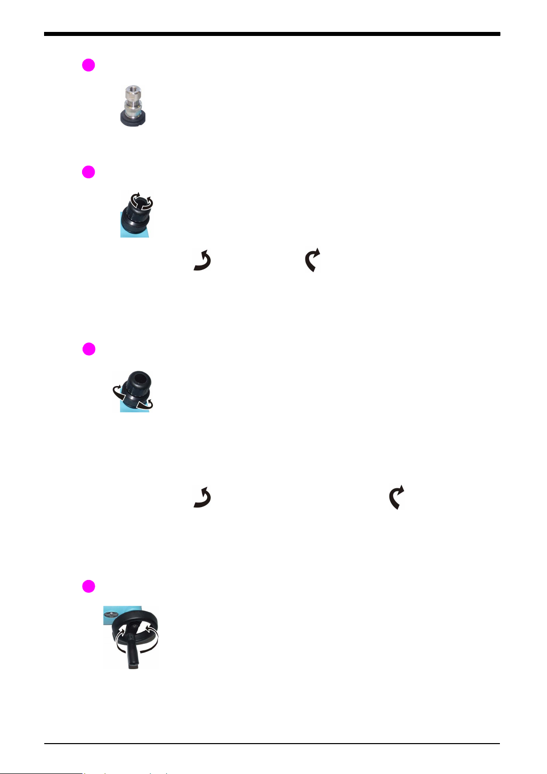
Chapter 1: Instrument parts,
Items 5, 9, 10: Not applicable
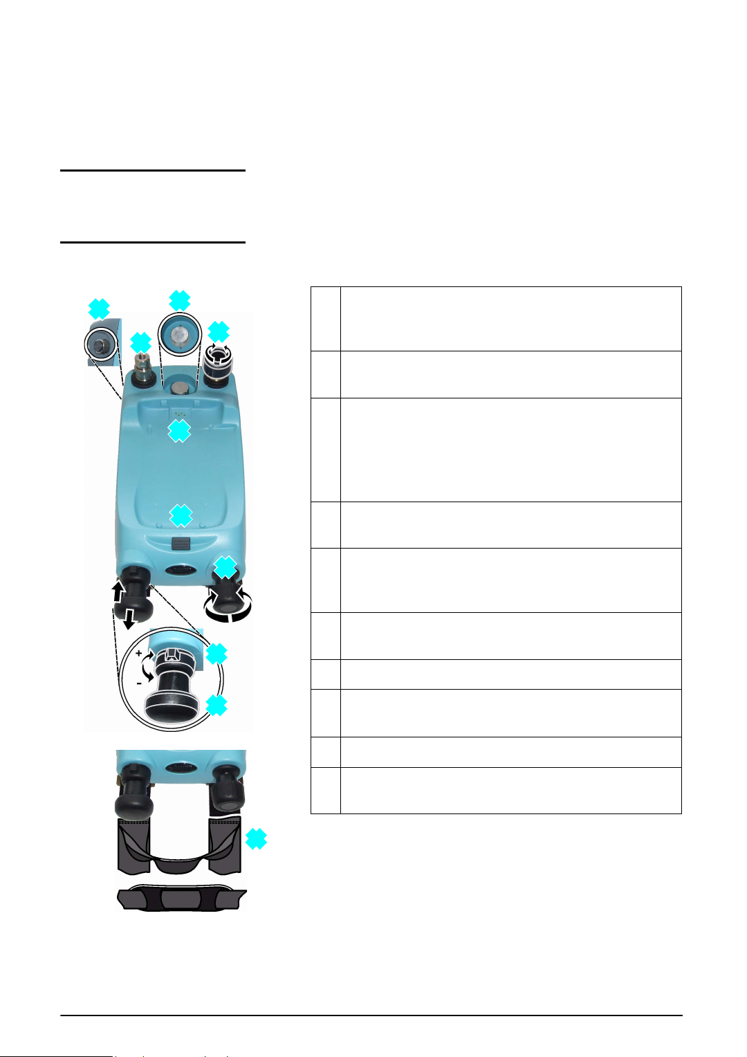
Figure 1-1: General views
1
2
3
4
6
7
8
11
12
13
1. Optional accessory: Pressure connection for a
pressure relief valve (PRV); see Section 1.2.1. A
blanking plug is standard.
2. Test port: Pressure connection (G1/8 or 1/8NPT) to
attach the device under test; see Section 1.2.2.
3. Pressure and electrical connections for a PM 620
module.
Seal the pressure connection with a blanking plug
(P/N IO620-BLANK) or a PM 620 module that has the
correct pressure rating.
4. Pneumatic pressure release valve to release pressure
in the system; see Section 1.2.3.
6. Moulded compartment for the DPI 620 calibrator with
electrical connections and a mechanism to hold it in
position.
7. Push-button mechanism to release the DPI 620
calibrator.
8. Pneumatic volume adjuster; see Section 1.2.4.
11. Pressure/vacuum selector to set the pump operation:
pressure (+), vacuum (-); see Section 1.2.5.
12. Pump mechanism; see Sect ion 1.2.6.
13. Carrying strap with a carry handle and a shoulder
strap.
accessories and options
1.1 Introduction
1.2 PV 621 models
This chapter gives a description of the different parts of each
instrument and the accessories/options available.
[EN] English - K0457 Instrument parts, accessories and options 1-1
Page 14
Issue 1
124
8
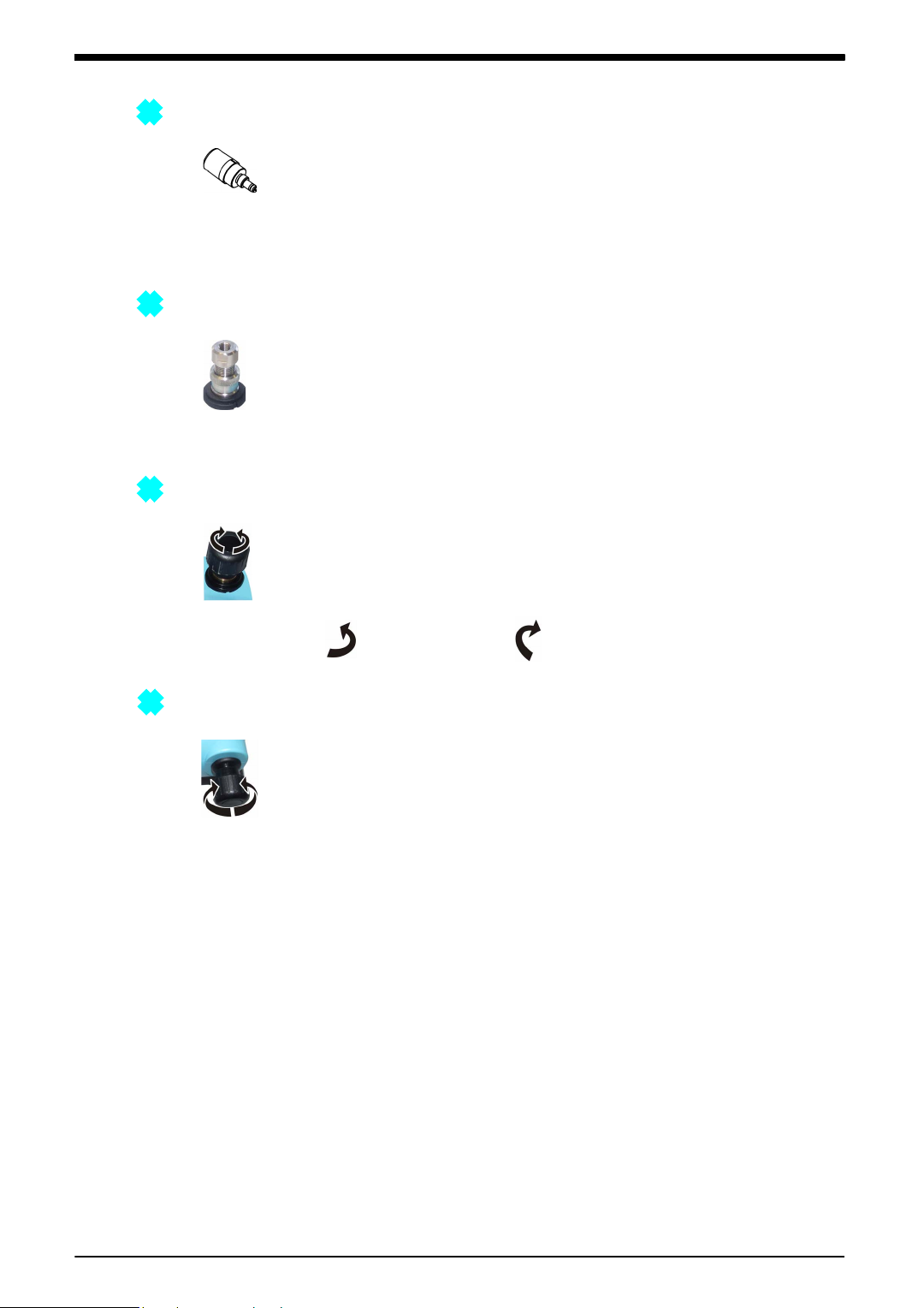
1.2.1 Pressure relief valve (PRV)
To give your attached devices overpressure prote ction (device
under test, PM 620 module), we recommend you use one of
our range of optional pneumatic PRVs; see Sect ion 1.5
(Accessories).
To attach or adjust a PRV, see Section 2.4.
1.2.2 Test port
To attach the device under test, the test port uses “Qui ck fit”
pressure adaptors; see Section 1.5 (Accessories). These are
easy to remove, change and install; see Section 2.3
(Attach/Remove the device under test).
1.2.3 Pneumatic pressure release valve
This is a needle point valve that lets you rel ease the pressure
or vacuum, or seal the system. You can also use it to control a
change in pressure conditi ons; f or example, to go to or t hrou gh
another test pressure.
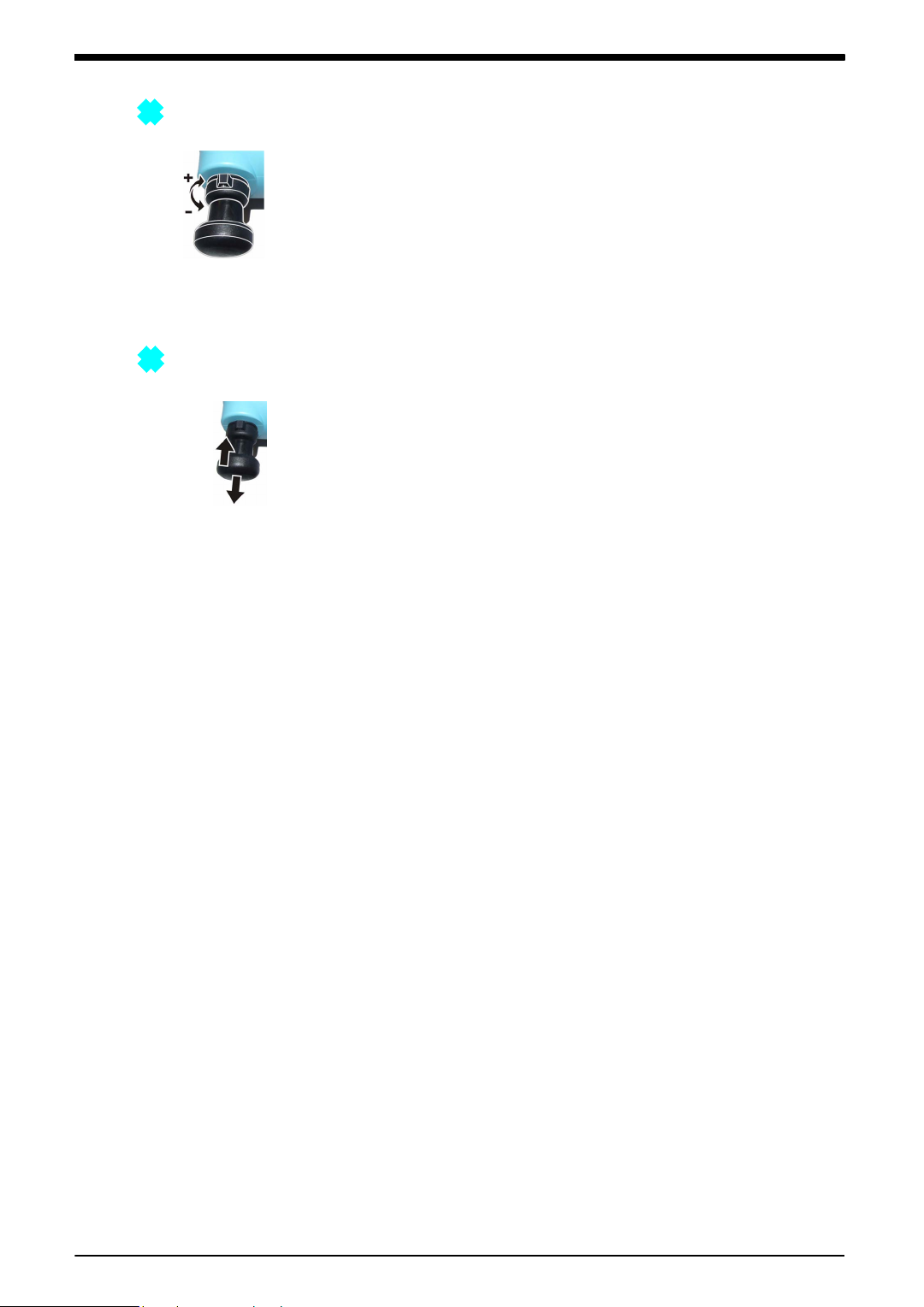
1.2.4 Volume adjuster
: Open : Close
This control increases or decreases the pressure/vacuum.
Before you seal the system (Section 1.2.3), turn this control to
the necessary position:
• for equal adjustment, turn it to the middl e of its range
• for maximum adjustment, turn it full y clockwise or
counterclockwise
When you have set the necessary pr essure or vacu um with t he
pump (Section 1.2.6), use the volume adjuster to make the last
adjustments.
1-2 Instrument parts, accessories and options K0457 - [EN] English
Page 15
1.2.5 Selector (pressure/vacuum)
11
12
Caution: Before you turn the pressure/vacuum selector
to + or -, release al l the pressur e. Sudden hi gh pressur e
in the pump mechanism can cause damage.
This control sets the operation of the instrument (pressure or
vacuum). To prevent a pressure leak, turn it fully clockwise or
counterclockwise.
Issue 1
+
: Pressure
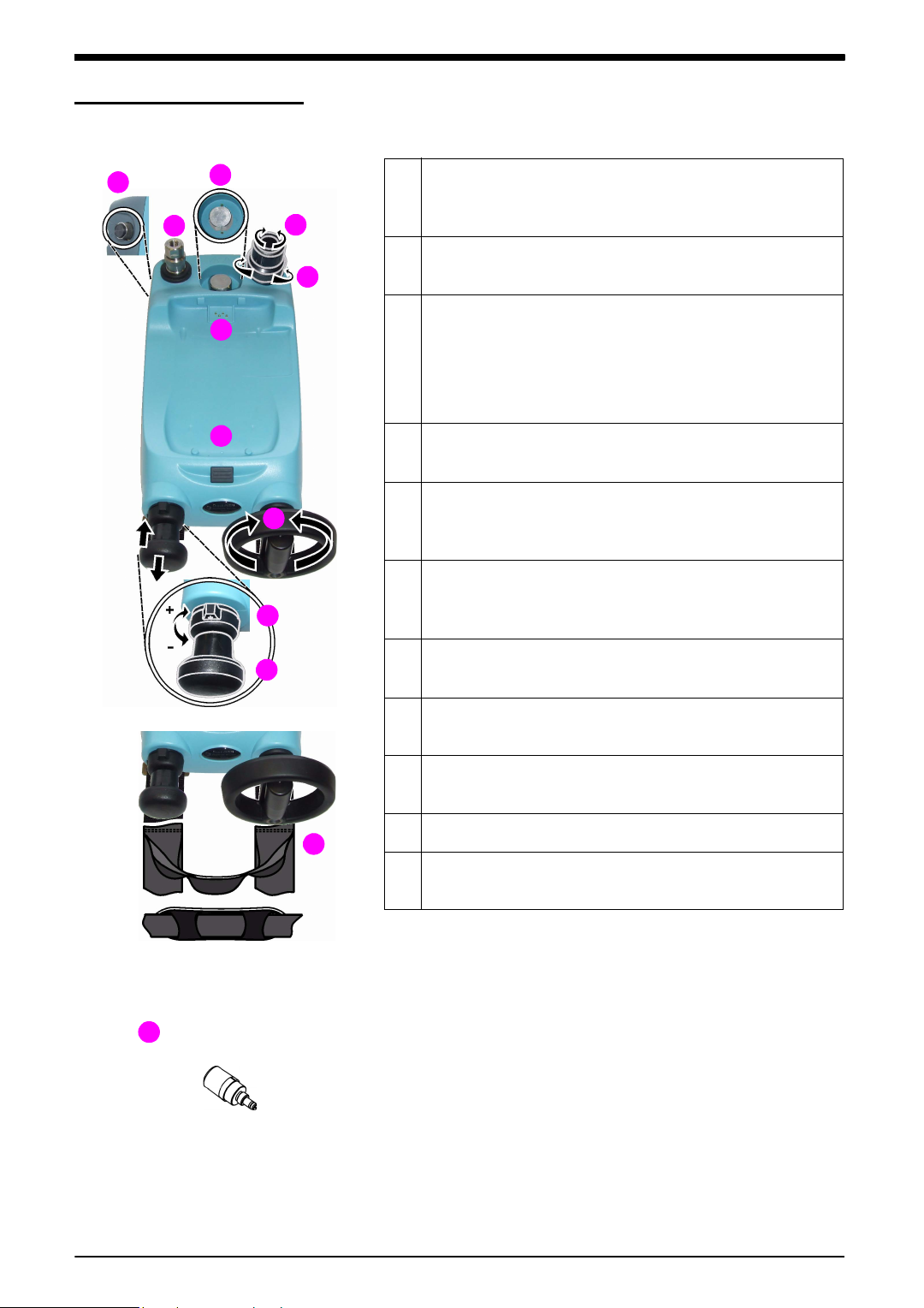
1.2.6 Pump (pressure/vacuum)
When you have set the operation to pressure or vacuum
(Section 1.2.5), seal the system (Section 1.2.3) and use the
pump to set the necessary pressure or vacuum.
You can then make the last adjustments with the volume
adjuster (Section 1.2.4).
-
: Vacuum
[EN] English - K0457 Instrument parts, accessories and options 1-3
Page 16
Issue 1
Items 8, 10: Not applicable
Figure 1-2: General views
1
2
3
4
5
7
6
9
11
12
13
1. Optional accessory: Pressure connection for a
pressure relief valve (PRV); see Section 1.3.1. A
blanking plug is standard.
2. Test port: Pressure connection (G1/8 or 1/8NPT) to
attach the device under test; see Section 1.3.2.
3. Pressure and electrical connections for a PM 620
module.
Seal the pressure connection with a blanking plug
(P/N IO620-BLANK) or a PM 620 module that has the
correct pressure rating.
4. Pneumatic pressure release valve to release pressure
in the system; see Section 1.3.3.
5. Pneumatic refill valve. Close it to seal off all the
pressure and refill the pressure mechanism; see
Section 1.3.4.
6. Moulded compartment for the DPI 620 calibrator with
electrical connections and a mechanism to hold it in
position.
7. Push-button mechanism to release the DPI 620
calibrator.
9. Volume adjuster wheel with fold-in handle; see
Section 1.3.5.
11. Pressure/vacuum selector to set the pump operation:
pressure (+), vacuum (-); see Section 1.3.6.
12. Pump mechanism; see Sect ion 1.3.7.
13. Carrying strap with a carry handle and a shoulder
strap.
2
1.3 PV 622 models
1.3.1 Pressure relief valve (PRV)
To give your attached devices overpressure prote ction (device
under test, PM 620 module), we recommend you use one of
our range of optional pneumatic PRVs; see Sect ion 1.5
(Accessories).
To attach or adjust a PRV, see Section 3.4.
1-4 Instrument parts, accessories and options K0457 - [EN] English
Page 17
1.3.2 Test port
2
4
5
9
To attach the device under test, the test port uses “Qui ck fit”
pressure adaptors; see Section 1.5 (Accessories). These are
easy to remove, change and install; see Section 3.3
(Attach/Remove the device under test).
1.3.3 Pneumatic pressure release valve
This is a needle point valve that lets you release the pressure
or vacuum, or seal the system. You can also use it to control a
change in pressure conditi ons; f or example, to go to or t hrou gh
another test pressure.
Open Close
Note: To release all the pressure in the sy stem, you must open
the refill valve (Section 1.3.4) one turn and then open the
pressure release valve one turn.
Issue 1
1.3.4 Pneumatic refill valve
When the refill valve is open, you have full control to increase
or decrease the pressure/vacuum with the volume adjus ter
(Section 1.3.5).
If you increase pressure and the volume adjuster gets to the
limit of travel, cl ose the refill valve. This seals off all the
pressure in the test port and the pressure module connection.
You can then use the pump and volume adjuster to refill the
pressure mechanism (Section 1.3.5).
Note: To release all the pressure in the sy stem, you must open
the refill valve one turn and then open the pressure release
valve (Section 1.3.3) one turn.
1.3.5 Volume adjuster wheel
The refill valve (Section 1.3.4) sets the operation of the Volume
adjuster wheel: Full control or refill
Open (1 turn): Full control Close: Refill
[EN] English - K0457 Instrument parts, accessories and options 1-5
Page 18

Issue 1
1
2
2
+
3
+
-
1
Full control When the refill valve is open, you have full control to increase
or decrease the pressure/vacuum. Before you seal the system
(Section 1.3.3), turn the wheel to the necessary position:
• for equal adjustment, turn it to the middl e of its range
• for maximum adjustment, turn it full y clockwise or
counterclockwise
When you have set the applicable pressure or va cuum with the
pump (Section 1.3.7), use the volume adjuster.
At higher pressures, it is easier to turn the wheel if you fold in
the handle:
1. Pull the handle out from the recess t hat locks it in position.
2. Fold the handle back against the wheel.
Refill If you increase pressure and the volume adjuster gets to the
limit of travel, close the refill valve (Sec tion 1.3.4). Y ou can then
use the pump and volume adjuster to refill the pressure
mechanism:
1. Close the refill val ve and wind the vol u me adjuster fully
counterclockwise. There is no change in pressure to the
device under test or the PM 620 module (if applicable).
2. Refill the pressure mechanism with the pump (≈ 15 cycles)
and wind the volume adjuster clockwise until the pres sure
starts to increase.
3. Open the refill valve to get full control again.
1-6 Instrument parts, accessories and options K0457 - [EN] English
Page 19

1.3.6 Selector (pressure/vacuum)
11
12
Caution: Before you turn the pressure/vacuum selector
to + or -, release al l the pressur e. Sudden hi gh pressur e
in the pump mechanism can cause damage.
This control sets the operation of the instrument (pressure or
vacuum). To prevent a pressure leak, turn it fully clockwise or
counterclockwise.
Issue 1
+
: Pressure
1.3.7 Pump (pressure/vacuum)
When you have set the operation to pressure or vacuum
(Section 1.3.6), seal the system (Section 1.3.3) and use the
pump to set an applicable pressure or vacuum:
You can then make the last adjustments with the volume
adjuster (Section 1.3.5).
-
: Vacuum
[EN] English - K0457 Instrument parts, accessories and options 1-7
Page 20

Issue 1
Items 5, 8, 11, 12: Not applicable
Figure 1-3: General views
7
1
6
2
3
4
10
9
13
1. Optional accessory: Pressure connection for a
pressure relief valve (PRV); see Section 1.4.1. A
blanking plug is standard.
2. Test port: Pressure connection (G1/8 or 1/8NPT) to
attach the device under test; see Section 1.4.2.
3. Pressure and electrical connections for a PM 620
module.
PV 623 models only: The pressure connection seals
itself.
4. Hydraulic pressure release valve to release pressure
in the system.
It also gives access to the hydraulic fluid reservoir; see
Section 1.4.3.
6. Moulded compartment for the DPI 620 calibrator with
electrical connections and a mechanism to hold it in
position.
7. Push-button mechanism to release the DPI 620
calibrator.
9. Volume adjuster wheel with fold-in handle; see
Section 1.4.5.
10. Hydraulic refill valve. Close it to seal off all the
pressure and refill the pressure mechanism with fluid;
see Section 1.4.4.
13. Carrying strap with a carry handle and a shoulder
strap.
1
1.4 PV 623 models
1.4.1 Pressure relief valve (PRV)
To give your attached devices overpressure prote ction (device
under test, PM 620 module), we recommend you use one of
our range of optional hydraulic PRVs; see Section 1.5
(Accessories).
To attach or adjust a PRV, see Section 4.5.
1-8 Instrument parts, accessories and options K0457 - [EN] English
Page 21

1.4.2 Test port
2
4
10
To attach the device under test, the test port uses “Qui ck fit”
pressure adaptors; see Section 1.5 (Accessories). These are
easy to remove, change and install; see Section 4.4
(Attach/Remove the device under test).
1.4.3 Hydraulic pressure release valve/reservoir access
This valve lets you release the pressure or seal the system.
Open Close
Note: To release all the pressure in the sy stem, you must open
the refill valve (Section 1.4.4) one turn and then open the
pressure release valve one turn.
If you remove the valve (counterclockwise), you can also do
these operations:
Issue 1
• add hydraulic fluid to the reservoir; see Section 4.2
• drain all the hydraulic fluid from the instrument; see
Section 4.7
1.4.4 Hydraulic refill valve
When the refill valve is open, you have full control to increase
or decrease the pressure with the volume adjuster
(Section 1.4.5).
If you increase pressure and the volume adjuster gets to the
limit of travel, cl ose the refill valve. This seals off all the
pressure in the test port and the pressure module connection.
You can then use the volume adjuster to refill the pressure
mechanism (Section 1.4.5).
Note: To release all the pressure in the sy stem, you must open
the refill valve one turn and then open the pressure release
valve (Section 1.4.3) one turn.
Open (1 turn): Full control Close: Refill
[EN] English - K0457 Instrument parts, accessories and options 1-9
Page 22

Issue 1
9
1
2
+
2
+
-
1
1.4.5 Volume adjuster wheel
The refill valve (Section 1.4.4) sets the operation of the Volume
adjuster wheel: Full control or refill
Full control When the refill valve is open, you have full control to increase
or decrease the pressure.
At higher pressures, it is easier to turn the wheel if you fold in
the handle:
1. Pull the handle out from the recess t hat locks it in position.
2. Fold the handle back against the wheel.
Refill If you increase pressure and the volume adjuster gets to the
limit of travel, close the refill valve (Sec tion 1.4.4). Y ou can then
use the volume adjuster to refill the pressure mechanism:
1. Close the refill valve and then wind the volume adjus ter fully
counterclockwise and clockwise until the pressure starts to
increase.
The counterclockwise operation refills the pressure
mechanism without a change in pressure to the device
under test or the PM 620 module (if applicable).
2. Open the refill valve to get full control again.
1-10 Instrument parts, accessories and options K0457 - [EN] English
Page 23

1.5 Accessories
Figure 1-4: Accessories included
2
4
1
3
5
1. “Quick fit” pressure adaptors (G1/8 and 1/8NPT); easy
to remove, change and install
2. Carrying strap with a shoulder strap and a carry
handle
3. PV 623 models only: Refill bottle for hydraulic fluid
4. Safety and quick reference guide
5. CD with the user manual
Figure 1-5: Optional accessories f or
the PV 62x pressure stations
9
8
7
6
6. P/N IO620-CASE-3. Fabric carry case with a shoulder
strap and a large pocket for accessories. It can hold
one PV 62x pressure station; one DPI 620 calibrator;
one PM 620 module.
7. P/N IO620-CASE-4. Rigid trolley case to hold a set of
units: one DPI 620 calibrator; two PV 62x pressure
stations; MC 620 module carrier; all the related
accessories.
The case includes: an extendable handle;
7 double-step latches that lock the lid down onto a
neoprene o-ring; an automatic pressure equalisation
valve.
8. Pressure modules (PM 620); refer to Chapter 7
(Specification)
9. Pneumatic PRVs to give attached devices
overpressure protection; see Table 1-1
Table 1-1: Recommended PRVs (Pneumatic)
PRV P/N Recommended
for:
Factory setting Adjustable range
Bar PSI Bar PSI
IO620-PRV-P1
IO620-PRV-P2
IO620-PRV-P3
PV 621, PV 62217
30
15
100
435
0.4 to 1
3 to 7
15 to 30
6 to15
45 to 100
220 to 435
IO620-PRV-P4
IO620-PRV-P5
PV 622 only
60
100
870
1500
30 to 60
50 to 100
435 to 870
725 to 1500
Issue 1
[EN] English - K0457 Instrument parts, accessories and options 1-11
Page 24

Issue 1
10
10. Hydraulic P RV s to gi ve att ach ed devi ces ov erpr essure
protection; see Table 1-2.
Table 1-2: Recommended PRVs (Hydraulic)
PRV P/N Recommended
for:
Factory setting Adjustable range
Bar PSI Bar PSI
IO620-PRV-H1
IO620-PRV-H2
IO620-PRV-H3
IO620-PRV-H4
IO620-PRV-H5
PV 623 only
50
200
400
700
1000
725
3000
6000
10000
15000
10 to 50
50 to 200
200 to 400
300 to 700
600 to 1000
145 to 725
725 to 2900
2900 to 5800
4350 to 10000
8700 to 15000
11. Pneumatic hose kit rated to 400 bar (5800 psi) with
“Quick fit” connectors for the test port.
P/N IO620-HOSE-P1: 1 metre (≈ 39”)
P/N IO620-HOSE-P2: 2 metre (≈ 78”)
12. Hydraulic hose kit rated to 1000 bar (15000 psi) with
“Quick fit” connectors for the test port.
P/N IO620-HOSE-H1: 1 metre (≈ 39”)
P/N IO620-HOSE-H2: 2 metre (≈ 78”)
13. Pressure adaptor sets:
P/N IO620-BSP: G1/8, G1/4 male; G1/4, G3/8 and
G½ female
P/N IO620-NPT: 1/8NPT, ¼NPT male, ¼NPT , 3/8NPT,
and ½NPT female
P/N IO620-MET: M14 x 1.5 and M20 x 1.5 female
14. P/N IO620-BLANK. Blanking plug to seal the pressure
port for the PM 620 module.
15. P/N IO620-COMP. Comparator. Attach it to the test
port and then use it to compare the device under test
with a reference device.
Figure 1-5: Opt ional accessories f or
the PV 62x pressure stations
(Continued)
15
13
14
11
12
1-12 Instrument parts, accessories and options K0457 - [EN] English
Page 25

Chapter 2: Pneumatic pressure
1
13
4
2
operation (PV 621)
2.1 Introduction
2.2 Release the pressure
Chapter 1 gives a description of the different parts of the
instrument: to
This chapter gives examples of how to connect and use the
PV 621 pressure station to give the necessary pressure or
vacuum conditions.
Before you start:
• Read and understand the “Safety” section.
• Make sure that there is no damage to the instrument, and
that there are no missing items.
Note: Use only original p arts supplied by the manufacturer.
To release all the pressure in this instrument, open the
pressure release valve countercloc kwise (1 turn).
To control a change in pressure conditions (for example, to go
to or through another test pressure) use the volume adjuster
(Section 1.2.4) or open and close the pressure release valve.
2.3 Attach/Remove the device under test
WARNING: Pre ssurized gases and fluids are dangerous.
Before you attach or disconnect pressure equipment,
safely release all the pressure.
Caution: To prevent damage to the instrument, do not
let dirt get into the pressure mechanism. Before you
attach equipment, make sure it is clean.
The test port uses “Quick fit” pressur e adaptors; see
Section 1.5 (Accessories). These are easy to remove, change
and install (Section 2.3.1).
[EN] English - K0457 Pneumatic pressure operation (PV 621) 2-1
Page 26

Issue 1
3. Attach the adaptor to the device; if
necessary use one of the alternative
adaptors in Section 1.5 (Accessories),
then tighten to the applicable torque.
4. Re-attach the adaptor to the test port and
tighten it until it is hand tight only.
Step Procedure
Step Procedure
1. Remove the adaptor
2. Use an applicable seal for the pressure
connection:
a. NPT type: Use an applicable sealant
on the thread.
b. BSP (parallel) type: We recommend a
bonded seal at the bottom.
c. BSP (parallel) type, 100 bar
(1500 psi) or less: a bonded seal at
the top is permitted.
1
4
3
2
NPT
a.
c.
(G) / BSPP
P ≤ 100 bar
b.
(G) / BSPP
1
2.3.1 Procedure (to attach)
2.3.2 Procedure (to remove)
To remove a device, release the pressure first (Section 2.2).
You can then do steps 4, 3, and 1 in Section 2.3.1 but do the
operations in the opposite direction.
2.4 Attach/Adjust a
PRV
WARNING: Pre ssurized gases and fluids are dangerous.
Before you attach or disconnect pressure equipment,
safely release all the pressure.
Optional accessory; see Section 1.5 (Access ories). Use a
pneumatic pressure relief valve (PRV) to set a limit to the
pressure you can apply to the pressure device s attached to the
pressure station. The PR V i s set at the fact ory to operat e at the
maximum pressure specified on the label.
If the pressure in the instrument is more t han the relief pressure
set for the PRV, the PRV controls a slow release of the
unwanted pressure. The correct PRV helps prevent
overpressure and damage to the attached devices.
To adjust the PRV, see Section 2.4.2.
2-2 Pneumatic pressure operation (PV 621) K0457 - [EN] English
Page 27

Issue 1
1 2
a
b
c
d
2.4.1 Procedure (to attach)
2.4.2 Procedure (to adjust)
1. Steps (a) and (b): Remove the blanking pl ug or , if applicabl e,
the PRV you are using.
Note: Before you put it into storage, make sure it is clean and
dry.
2. Steps (c) and (d): Choose a clean, dry PRV with the correct
pressure value for the devices you are using and tighten it
into position (hand tight only).
Note: We only guarantee the pressure setting on the product
set at our factory.
The PRV is set at the factory to operate at the maximum
pressure specified on the label (on the plastic cap). For the
adjustable range, refer t o Table 1-1.
If necessary, use these steps to adjust the relief pressure:
1. Attach an applicable pressure indicator to the test port
(Section 2.3) or use a DPI 620 calibrator with a PM 620
module (Chapter 5).
2. Remove the plastic cap from the end of the PRV.
3. Loosen the locknut counterclockwise.
2.5 Vacuum or pressure operation
4. Set the necessary pressure with the pressure station (see
Section 2.5.2).
5. When the pressure in the pressure station is at th e new PRV
pressure, turn the adjustment screw until the PRV operates:
counterclockwise decreases the operating pressure
clockwise increases the operating pre ssure
6. Do steps 4 and 5 until the PRV operates at the correct
pressure. Then tighten the l ocknut an d pr ess the p las tic c ap
back into position.
After you correctly attach an applicable device to the test port
(Section 2.3), use these steps to set the necessary vacuum or
pressure. If applicable, attach the correct PRV (Section 2.4).
[EN] English - K0457 Pneumatic pressure operation (PV 621) 2-3
Page 28

Issue 1
1 2
3 4
+
-
5
1184128
1 2
3 4
+
-
5
1184128
2.5.1 Vacuum procedure
2.5.2 Pressure procedure
Step Procedure (Vacuum)
1. Set the pressure/vacuum selector to vacuum (-); fully
counterclockwise.
2. To do equal adjustments (up or down) at the end of
the procedure, turn the volume adjuster to the middle
of its range of operation.
To get the maximum vacuum, turn the volume adjuster fully
clockwise.
3. Seal the system.
4. Use the pump to set the maximum vacuum or set the
vacuum you want to adjust.
5. Adjust the vacuum: + decrease; - increase.
Step Procedure (Pressure)
1. Set the pressure/vacuum selector to pressure (+);
fully clockwise.
2. To do equal adjustments (up or down) at the end of
the procedure, turn the volume adjuster to the middle
of its range of operation.
3. Seal the system.
4. Use the pump to set the approximate pressure.
5. Adjust the pressure: + decrease; - increase.
2-4 Pneumatic pressure operation (PV 621) K0457 - [EN] English
Page 29

Chapter 3: Pneumatic pressure
1
13
5
4
5
4
2
operation (PV 622)
3.1 Introduction
3.2 Release the pressure
Chapter 1 gives a description of the different parts of the
instrument: to
This chapter gives examples of how to connect and use the
PV 622 pressure station to give the necessary pressure or
vacuum conditions.
Before you start:
• Read and understand the “Safety” section.
• Make sure that there is no damage to the instrument, and
that there are no missing items.
Note: Use only original p arts supplied by the manufacturer.
To release all the pressure in this instrument:
Step Procedure
1. Open the refill valve counterclockwise (1 turn).
2. Open the pressure release valve counterclockwise
(1 turn).
3.3 Attach/Remove the device under test
To control a change in pressure conditions (for example, to go
to or through another test pressure) use the volume adjuster
wheel (Section 1.3.5) or open and close the pressure rele ase
valve.
WARNING: Pre ssurized gases and fluids are dangerous.
Before you attach or disconnect pressure equipment,
safely release all the pressure.
Caution: To prevent damage to the instrument, do not
let dirt get into the pressure mechanism. Before you
attach equipment, make sure it is clean.
The test port uses “Quick fit” pressur e adaptors; see
Section 1.5 (Accessories). These are easy to remove, change
and install (Section 3.3.1).
[EN] English - K0457 Pneumatic pressure operation (PV 622) 3-1
Page 30

Issue 1
3. Attach the adaptor to the device; if
necessary use one of the alternative
adaptors in Section 1.5 (Accessories),
then tighten to the applicable torque.
4. Re-attach the adaptor to the test port and
tighten it until it is hand tight only.
Step Procedure
Step Procedure
1. Remove the adaptor
2. Use an applicable seal for the pressure
connection:
a. NPT type: Use an applicable sealant
on the thread.
b. BSP (parallel) type: We recommend a
bonded seal at the bottom.
c. BSP (parallel) type, 100 bar
(1500 psi) or less: a bonded seal at
the top is permitted.
1
4
3
2
NPT
a.
c.
(G) / BSPP
P ≤ 100 bar
b.
(G) / BSPP
1
3.3.1 Procedure (to attach)
3.3.2 Procedure (to remove)
To remove a device, release the pressure first (Section 3.2).
You can then do steps 4, 3, and 1 in Section 3.3.1 but do the
operations in the opposite direction.
3.4 Attach/Adjust a
PRV
WARNING: Pre ssurized gases and fluids are dangerous.
Before you attach or disconnect pressure equipment,
safely release all the pressure.
Optional accessory; see Section 1.5 (Access ories). Use a
pneumatic pressure relief valve (PRV) to set a limit to the
pressure you can apply to the pressure device s attached to the
pressure station. The PR V i s set at the fact ory to operat e at the
maximum pressure specified on the label.
If the pressure in the instrument is more t han the relief pressure
set for the PRV, the PRV controls a slow release of the
unwanted pressure. The correct PRV helps prevent
overpressure and damage to the attached devices.
To adjust the PRV, see Section 3.4.2.
3-2 Pneumatic pressure operation (PV 622) K0457 - [EN] English
Page 31

Issue 1
1 2
a
b
c
d
3.4.1 Procedure (to attach)
3.4.2 Procedure (to adjust)
1. Steps (a) and (b): Remove the blanking pl ug or , if applicabl e,
the PRV you are using.
Note: Before you put it into storage, make sure it is clean and
dry.
2. Steps (c) and (d): Choose a clean, dry PRV with the correct
pressure value for the devices you are using and tighten it
into position (hand tight only).
Note: We only guarantee the pressure setting on the product
set at our factory.
The PRV is set at the factory to operate at the maximum
pressure specified on the label (on the plastic cap). For the
adjustable range, refer t o Table 1-1.
If necessary, use these steps to adjust the relief pressure:
1. Attach an applicable pressure indicator to the test port
(Section 3.3) or use a DPI 620 calibrator with a PM 620
module (Chapter 5).
2. Remove the plastic cap from the end of the PRV.
3. Loosen the locknut counterclockwise.
3.5 Vacuum or pressure operation
4. Set the necessary pressure with the pressure station (see
Section 3.5.2).
5. When the pressure in the pressure station is at th e new PRV
pressure, turn the adjustment screw until the PRV operates:
counterclockwise decreases the operating pressure
clockwise increases the operating pre ssure
6. Do steps 4 and 5 until the PRV operates at the correct
pressure. Then tighten the l ocknut an d pr ess the p las tic c ap
back into position.
After you correctly attach an applicable device to the test port
(Section 3.3), use these steps to set the necessary vacuum or
pressure. If applicable, attach the correct PRV (Section 3.4).
[EN] English - K0457 Pneumatic pressure operation (PV 622) 3-3
Page 32

Issue 1
1
3
4
5 6
+
-
2
11
594
12
9
1
6
2
3
7
5
+
-
4
+
11
9
4
12
5
959129
3.5.1 Vacuum procedure
3.5.2 Pressure procedure
Step Procedure (Vacuum)
1. Set the pressure/vacuum selector to vacuum (-); fully
counterclockwise.
2. Open the refill valve (1 turn).
3. To do equal adjustments (up or down) at the end of the
procedure, turn the volume adjuster wheel to the
middle of its range of operation.
To get the maximum vacuum, turn the volume adjuster
wheel fully clockwise.
4. Seal the system.
5. Use the pump to set the maximum vacuum or set the
vacuum you want to adjust.
6. Adjust the vacuum: + decrease; - increase.
Step Procedure (Pressure)
1. Set the pressure/vacuum selector to pressure (+); fully
clockwise.
2. To do equal adjustments (up or down) at the end of the
procedure, turn the volume adjuster wheel to the
middle of its range of operation.
3. Seal the system.
4. Use the pump to set a pressure up to ≈ 20 bar
(300 psi).
5. Open the refill valve (1 turn). You now have full control
to increase (+) or decrease (-) the pressure with the
volume adjuster.
Note: At higher pressures, it is easier to turn the wheel if
you fold in the handle; see Section 1.3.5.
6. If you increase pressure and get to the limit of travel,
close the refill valve and wind the volume adjuster fully
counterclockwise.
There is no change in pressure to the device under test or
7. Refill the pressure mechanism with the pump
the PM 620 module (if applicable).
(≈ 15 cycles) and wind the volume adjuster clockwise
until the pressure starts to increase.
3-4 Pneumatic pressure operation (PV 622) K0457 - [EN] English
operation and then pump) until you get the necessary
pressure OR for full control, go back to step 5.
Continue this sequence (clockwise/counterclockwise
Page 33

Chapter 4: Hydraulic pressure
1
13
4 5
1
3
+
2
24494
operation (PV 623)
4.1 Introduction
4.2 Fill the reservoir
Chapter 1 gives a description of the different parts of the
instrument: to
This chapter gives examples of how to connect and use the
PV 623 pressure station to give the necessary hydraul ic
pressure conditions.
Before you start:
• Read and understand the “Safety” section.
• Make sure that there is no damage to the instrument, and
that there are no missing items.
Note: Use only original p arts supplied by the manufacturer.
Caution: Ice in the pressure mechanism can cause
damage. If the temperature is less than 4 °C (39°F), drai n
all water from the instrument.
The first time you want to use the hydraulic pressure station,
use this procedure to fill the reser voir:
Step Procedure
1. Use the applicable adaptor to attach the device
(Section 4.4).
[EN] English - K0457 Hydraulic pressure operation (PV 623) 4-1
2. Remove the hydraulic pressure release valve.
3. Use the refill bottle to add the necessary hydraulic
4. To remove air from the pressure mechanism, wind the
5. Seal the system and continue with the normal
* Refer to Chapter 7 (Specification)
*
but leave a small air gap.
fluid
volume adjuster through one full cycle
(counterclockwise then cloc k wis e).
pressure operation; see Section 4.6.
After a period of operation, if it is necessar y to add more fluid to
the reservoir, use this procedure again.
To add more fluid during a pressure procedure, refer to
Section 4.6.2.
To drain the hydraulic fluid, refer to Section 4.7.
Page 34

Issue 1
10
4
10
4
2
3. Attach the adaptor to the device; if
necessary use one of the alternative
adaptors in Section 1.5 (Accessories),
then tighten to the applicable torque.
4. Re-attach the adaptor to the test port and
tighten it until it is hand tight only.
Step Procedure
Step Procedure
1. Remove the adaptor
2. Use an applicable seal for the pressure
connection:
a. NPT type: Use an applicable sealant
on the thread.
b. BSP (parallel) type: We recommend a
bonded seal at the bottom.
c. BSP (parallel) type, 100 bar
(1500 psi) or less: a bonded seal at
the top is permitted.
1
4
3
2
NPT
a.
c.
(G) / BSPP
P ≤ 100 bar
b.
(G) / BSPP
4.3 Release the pressure
4.4 Attach/Remove the device under test
To release all the pressure in this instrument:
Step Procedure
1. Open the refill valve counterclockwise (1 turn).
2. Open the pressure release valve counterclockwise
(1 turn).
To control a change in pressure conditions (for example, to go
to or through another test pressure) use the volume adjuster
wheel (Section 1.4.5).
WARNING: Pre ssurized gases and fluids are dangerous.
Before you attach or disconnect pressure equipment,
safely release all the pressure.
Caution: To prevent damage to the instrument, do not
let dirt get into the pressure mechanism. Before you
attach equipment, make sure it is clean.
The test port uses “Quick fit” pressur e adaptors; see
Section 1.5 (Accessories). These are easy to remove, change
and install.
4.4.1 Procedure (to attach)
4-2 Hydraulic pressure operation (PV 623) K0457 - [EN] English
Page 35

Issue 1
1
3 4
a
b
c
d
1
1 2
4.4.2 Procedure (to remove)
4.5 Attach/Adjust a
PRV
To remove a device, release the pressure first (Section 4.3).
You can then do steps 4, 3, and 1 in Section 4.4.1 but do the
operations in the opposite direction.
WARNING: Pre ssurized gases and fluids are dangerous.
Before you attach or disconnect pressure equipment,
safely release all the pressure.
Caution: In its normal condition, the PV 623 model
contains hydraulic fluid. To make sure it does not spill
out, seal the system and put it on its side before you
install a PRV.
Optional accessory; see Section 1.5 (Access ories). Use a
hydraulic pressure relief val ve (PRV) to set a limit to the
pressure you can apply to the pressure device s attached to the
pressure station. The PR V i s set at the fact ory to operat e at the
maximum pressure specified on the label.
If the pressure in the instrument is more t han the relief pressure
set for the PRV, the PRV controls a slow release of the
unwanted pressure. The correct PRV helps prevent
overpressure and damage to the attached devices.
4.5.1 Procedure (to
4.5.2 Procedure (to
attach)
adjust)
To adjust the PRV, see Section 4.5.2.
1. Seal the system.
2. Put the instrument on its side.
3. Steps (a) and (b): Remove the blanking pl ug or , if applicabl e,
the PRV you are using. To collect possi ble drops of hy draulic
fluid, put it in a container.
Note: Before you put it into storage, make sure it is clean and
dry.
4. Steps (c) and (d): Choose a clean, dry PRV with the correct
pressure value for the devices you are using and tighten it
into position (hand tight only).
Note: We only guarantee the pressure setting on the product
set at our factory.
The PRV is set at the factory to operate at the maximum
pressure specified on the label (on the plastic cap). For the
adjustable range, refer t o Table 1-2.
If necessary, use these steps to adjust the relief pressure:
[EN] English - K0457 Hydraulic pressure operation (PV 623) 4-3
1. Attach an applicable pressure indicator to the test port
(Section 4.4) or use a DPI 620 calibrator with a PM 620
module (Chapter 5).
Page 36

Issue 1
1
4
2
3
+
-
+
4
9
10
9
10
9
10
2. Remove the plastic cap from the end of the PRV.
3. Set the necessary pressure with the pressure station (see
Section 4.6.1).
4. When the pressure in the pressure station is at th e new PRV
pressure, turn the adjustment screw until the PRV operates:
counterclockwise decreases the operating pressure
clockwise increases the operating pre ssure
5. Do steps 3 and 4 until the PRV operates at the correct
pressure. Then press the plastic cap back into position.
4.6 Pressure operation
After you correctly attach an applicable device to the test port
(Section 4.4), use these steps t o set the nec essar y pressur e. I f
applicable, attach the correct PRV (Section 4.5).
Note: To operate correctly, make sure the reservoir contains
the correct amount of hydraulic fluid; see Sect ion 4.2.
During the procedure, you can add more hydraulic fluid; see
Section 4.6.2. When the procedure is complete, you can then
drain this fluid back out of the device; see Section 4.6.3.
4.6.1 Hydraulic pressure procedure
Step Procedure
1. Seal the system.
2. Close the refill valve and then wind the volume
adjuster fully clockwise and counterclockwise until the
pressure starts to increase.
Continue the clockwise/counterclockwise sequence until
you get the necessary pressure OR for full control, go to
step 3.
3. For full control, open the refill valve (1 turn). You can
The counterclockwise operation refills the pressure
mechanism but there is no change in pressure to the
device under test or the PM 620 module (if applicable).
Note: At higher pressures, it is easier to turn the wheel if
you fold in the handle; see Section 1.4.5.
now increase (+) or decrease (-) the pressure with the
volume adjuster.
4. If you increase pressure and get to the limit of travel,
4-4 Hydraulic pressure operation (PV 623) K0457 - [EN] English
5. Continue to do steps 2 to 4 until you get the necessary
close the refill valve again and wind the volume
adjuster fully counterclockwise.
pressure.
Page 37

4.6.2 Add more hydraulic fluid
4 5
3
+
21
10
449
4
If the device under test has a large fluid capacity, you can add
hydraulic fluid during the pressure procedure.
Issue 1
Step Procedure
1. To seal off all the pressure in the test port and the
pressure module connection, close the refill valve.
2. Remove the hydraulic pressure release valve.
3. Use the refill bottle to add the necessary hydraulic
4. To remove air from the pressure mechanism, wind the
5. Seal the system and continue with the normal
* Refer to Chapter 7 (Specification)
*
but leave a small air gap.
fluid
Note: To prevent contamination use only one type of
hydraulic fluid in the instrument.
volume adjuster through one full cycle
(counterclockwise then clock wis e).
pressure procedure; see Section 4.6.1.
4.6.3 Drain hydraulic fluid from the device under test
If you add more hydraulic fluid during the pressure procedure,
drain this fluid out of the devic e when the pressure procedure i s
complete.
Note: If it is safe and there is no risk of contamination, you can
leave the hydraulic fluid inside the device.
Preparation To drain the device, we recommend these items:
[EN] English - K0457 Hydraulic pressure operation (PV 623) 4-5
• the applicable skin and eye protection
• a container that is large enough to hold the hydraulic fluid
and prevent contamination of the work surface
• applicable materials to make sure the instrument and the
Procedure 1. Release the pressure (Section 4.3).
area stay clean; see Chapter 6 (Maintenance procedures)
2. Remove the device (Section 4.4) but do not let fluid spill
onto the PV 62x instrument.
3. If necessary, drain the hydraulic fluid from the device under
test.
Note: To discard the hydraulic fluid, obey all the local health
and safety procedures.
Page 38

Issue 1
1 2
4
+
3
249
4.7 Drain all the hydraulic fluid
4.7.1 Preparation
4.7.2 Procedure
In some conditions, it is necessary to fully drain the hydraulic
fluid from your PV 62x pressure station; for example:
• if you are using water and the storage or operating
temperature is going to be less than 4°C (39°F)
• if there is a long period of storage
• if there is unwanted material in the hydraulic fluid
To drain the instrument, we recommend these items:
• the applicable skin and eye protection
• a container that is large enough to hold the hydraulic fluid
and prevent contamination of the work surface
• applicable materials to make sure the instrument and the
area stay clean; see Chapter 6 (Maintenance procedures)
Step Procedure (Drain all the fluid)
1. If applicable, release the pressure (Section 4.3) and
remove the device (Section 4.4).
Note: If it is attached, we also recommend you remove the
DPI 620 calibrator; see Chapter 5 (Pressure calibrator
operation (DPI 620)).
2. Remove the hydraulic pressure release valve.
3. Wind the volume adjuster wheel fully clockwise; this
moves the fluid out of the pressure mechanism.
4. Put a container below the instrument then tilt the instrument
up until all the fluid has come out. To discard the hydraulic
fluid, obey all the local health and safety procedures.
Note: Fluid comes out of the test port and the connection
for the pressure release valve.
5. To flush out fluids that contain unwanted material, refill the
system and repeat steps 3 and 4.
Note: To prevent contamination use only one type of
hydraulic fluid in the instrument.
4-6 Hydraulic pressure operation (PV 623) K0457 - [EN] English
Page 39

Chapter 5: Pressure calibrator
1
2 3
6
4
5
operation (DPI 620)
5.1 Introduction
5.2 Parts and assembly
5.2.1 DPI 620 calibrator parts
This section gives examples of how to connect and use the
pressure stations to do pressure calibrations with the DPI 620
calibrator and the applicable pressure modules (PM 620).
Before you start:
• Read and understand the “Safety” section.
• Do not use a damaged instrument.
Note: Use only original p arts supplied by the manufacturer.
To make a fully integrated pressure calibrator instrument, use
these items:
• a PV 62x pressure station; see Chapter 1 (Instrument pa rt s,
accessories and options)
• a DPI 620 calibrator; see Section 5.2.1
• an applicable PM 620 module for the pressure station; see
Section 5.2.2
Refer to the user manual - K0449: Druck DPI 620 Advanced
modular calibrator.
1. On or off button. Press and hold the button down until the
power comes on.
2. Channel 1 (CH1) connectors for electrical measure and
source operations; refer to the user manual - K0449
3. Isolated channel 2 (CH2) connectors for electrical measure
and source operations and a 24V loop power supply (24Vo);
refer to the user manual - K0449
4. Rubber pull-down cover for the USB type A connector; USB
mini-type B connector and +5V DC power input soc ket.
5. Colour display with touch-screen. The number of windows
you see on the display is set by the number of task selections
and external modules you are working with (maximum: 6).
T o make a selection, lightly tap on the applicable display area;
refer to the user manual - K0449
6. Sealed speaker unit.
[EN] English - K0457 Pressure calibrator operation (DPI 620) 5-1
Page 40

Issue 1
1
a
1
2
3
4
5
5.2.2 PM 620 module parts
5.2.3 Assembly instructions
Caution: To pr event damage to the PM 620 module, only
use it within the specified pressure limit on the label.
1. Pressure module (PM 620) with a pressure connection,
reference port (a) and a label. The label includes:
Pressure range. Example: 20 bar g (g: gauge; a: absolute);
serial number (S/ N); manufacturer: name, address, website
Table 5-1: Recommended pressure modules (PM 620)
PV 62x model PM 620 module range
PV 621 models 25 mbar to 20 bar (0.36 to 300 psi)
PV 622 models 25 mbar to 100 bar (0.36 to 1500 psi)
PV 623 models 70 to 1000 bar (1000 to 15000 psi)
Step Procedure
1. Lower the DPI 620 calibrator into the moulded
compartment.
2. Press on the bottom end of the calibrator until it
latches in position.
3. Attach a PM 620 module with the correct range
and type.
4. Tighten it until it is hand tight only.
When this symbol flashes at the top of the display,
it shows there is communication between the
module and the calibrator.
5. If applicable, attach one of the optional PRVs; see
Chapter 1 (Instrument parts, accessories
and options).
5-2 Pressure calibrator operation (DPI 620) K0457 - [EN] English
Page 41

Issue 1
TAP
2
1
3
A
3
C
B
A
B
C
1
D
D
1
E
TAP
E
5.3 Measure pressure/vacuum
5.3.1 Procedure overview
When the pressure calibrator assembly is complete
(Section 5.2), use the calibrator to measure the pressure or, if
applicable, the vacuum in the pressure station; for example: to
calibrate a gauge or indicator.
To use the pressure calibrator, complete these procedures:
• Set the calibrator functions you want to use on the displ a y:
a. Pressure function (P1): item ;
see Section 5.3.2
b. CH1: Channel 1 electrical function (input or output);
refer to the user manual - K0449
c. CH2: Channel 2 electrical function (input or output);
refer to the user manual - K0449
d. other functions (maximum: 6 functions);
refer to the user manual - K0449
• If necessary, change the Units for the function: item ;
see Section 5.3.3
• If necessary, set a Utility for the function: item
a. Max/Min/Avg; refer to the user manual - K0449
b. Switch Test; refer to the user manual - K0449
c. Leak Test; see Section 5.3.4
• If necessary, change the Settings for the pressure function:
item
a. Process (Tare, Alarm, Filter, Flow, Scaling);
refer to the user manual - K0449
b. Leak Test (Only wh en the Utility is set); see Section 5.3.4
c. Zero; see Section 5.3.5
• If necessary, change the Process for the CH1 and/or CH2
input functions: item
This includes: Tare, Alarm, Filter, Flow, Scaling; refer to the
user manual - K0449
[EN] English - K0457 Pressure calibrator operation (DPI 620) 5-3
Page 42

Issue 1
1
F
TAP
F
G
2
1
G
TAP
Channel SettingsTask Settings
Task SettingsSelect Function Channel Settings
1
2
3
4
86 7
5
• If necessary, change the Automation options for the CH1
and/or CH2 output functions: item
This includes: Nudge, Span Check, Percent Step,
Defined Step, Ramp; refer to the user manual - K0449
• If necessary, change the Configuration: item
This includes: Data Logging, Documenting, and Advanced
options; refer to the user manual - K0449
• When all the software selections are complete, make the
applicable pressure and electrical connections. Examples:
Gauge/indicator calibration (Section 5.3.6); Transmitter
calibration (Section 5.3.7); Switch test (Section 5.3.8)
5.3.2 DPI 620 calibrator: Set the pressure function
This example shows the sequence to set t he pressure funct ion.
It is a similar procedure for other functions; refer to the user
manual - K0449.
5-4 Pressure calibrator operation (DPI 620) K0457 - [EN] English
Page 43

5.3.3 DPI 620 calibrator: Set the pressure units
Channel SettingsTask Settings
TAP
2
1
3
4
5
6
Select Units Select Units
Channel Settings
Task Settings
7 8
Channel SettingsTask Settings
TAP
2
1
3
4
5
6
Select Utility Select Utility
Channel Settings
Task Settings
7 8
This example shows the sequence to set the pressure units. It
is a similar procedure for other units.
Issue 1
5.3.4 DPI 620 calibrator: Set up a Leak Test
To do a leak test, set the Utility to Leak Test and then set the
Leak Test options in Settings:
(1) Set the Utility
[EN] English - K0457 Pressure calibrator operation (DPI 620) 5-5
Page 44

Issue 1
2
1
3
4
Select Leak Test Select Test Time
Steps 5 and 6: Set the Test Time
+ Set the Wait Time (if necessary)
TAP the wind ow
(Maximise)
Select Settings
5
6
7
Start the test and let it
complete.
Go back to the Home window. Start the test
when the pressure system is set up.
Stop the test (with no results)
(2) Set the Leak Test
options
When you have set the Utility to Leak Test, you can set these
options:
Wait Time: The time before the test starts in
hours:minutes:seconds (hh:mm:ss)
Test Time: The period of the leak test in
hours:minutes:seconds (hh:mm:ss)
Note: To set the Leak Test options, you must have a PM 620
module correctly installed (Section 5.2.3).
5.3.5 DPI 620 calibrator: Set the PM 620 module to zero
5-6 Pressure calibrator operation (DPI 620) K0457 - [EN] English
Use this option to write a new zero pressure value to the
PM 620 module you are using. This option only affects gauge
type modules.
Note: To make a temporary adjustment for zero, you can use
the Tare function: Select Settings > Process > Tare (refer to the
user manual - K0449).
Page 45

Issue 1
21
3
4
Select Zero Accept the adjustment value
TAP the wind ow
(Maximise)
Select Settings
See the new reading and go back to the H ome
window.
5
2
1 3 4
5.3.6 Example procedure: Gauge/indicator calibration
1. Assemble the pressure calibrator with the correct PM 620
module and PRV (if applicable); see Section 5.2.3.
2. Set the applicable software options; see Section 5.3.1
(Procedure overview). This example shows one function:
• Pressure (P1) is set to measure the pressure supplied by
the pressure station.
3. To attach the device under test, use the specified
procedures for your PV 62x pressure station*.
[EN] English - K0457 Pressure calibrator operation (DPI 620) 5-7
Page 46

Issue 1
2
1
3
5
4
4. To s et the necessa ry pressure or vac uum for the calibrat ion,
use the specified procedures for your PV 62x pressure
station*.
* Reference • PV 621 models: see Chapter 2 (Pneumatic pressure
operation (PV 621))
• PV 622 models: see Chapter 3 (Pneumatic pressure
operation (PV 622))
• PV 623 models: see Chapter 4 (Hydraulic pressure
operation (PV 623))
5.3.7 Example procedure: Transmitter calibration
1. Assemble the pressure calibrator with the correct PM 620
module and PRV (if applicable); see Section 5.2.3.
2. Set the applicable software options; see Section 5.3.1
(Procedure overview). This example shows two func tions:
• Channel 2 (CH2) is set to measure current with 24V loop
power.
• Pressure (P1) is set to measure the pressure supplied by
the pressure station.
3. To attach the device under test, use the specified
procedures for your PV 62x pressure station*.
5-8 Pressure calibrator operation (DPI 620) K0457 - [EN] English
Page 47

* Reference • PV 621 models: see Chapter 2 (Pneumatic pressure
2
1
3
5
4
6
operation (PV 621))
• PV 622 models: see Chapter 3 (Pneumatic pressure
operation (PV 622))
• PV 623 models: see Chapter 4 (Hydraulic pressure
operation (PV 623))
4. Complete the electrical connections. This example shows
Channel 2 (CH2) set up to measure current with 24V loop
power.
5. To s et the necessa ry pressure or vac uum for the calibrat ion,
use the specified procedures for your PV 62x pressure
station*.
5.3.8 Example procedure: Switch test
Issue 1
1. Assemble the pressure calibrator with the correct PM 620
module and PRV (if applicable); see Section 5.2.3.
2. Set the applicable software options; see Section 5.3.1
(Procedure overview). This example shows one function:
• Pressure (P1) is set to measure the pressure. The Utility is
set to Switch Test.
[EN] English - K0457 Pressure calibrator operation (DPI 620) 5-9
3. To attach the device under test, use the specified
procedures for your PV 62x pressure station*.
Page 48

Issue 1
Closed
Open
Reset
* Reference • PV 621 models: see Chapter 2 (Pneumatic pressure
operation (PV 621))
• PV 622 models: see Chapter 3 (Pneumatic pressure
operation (PV 622))
• PV 623 models: see Chapter 4 (Hydraulic pressure
operation (PV 623))
4. Complete the electrical connections. This example shows
Channel 2 (CH2) set up to monitor the switch condition.
5. Slowly apply pressure to the system until the switch
changes condition (open or closed) - use the specified
procedures for your PV 62x pressure station*.
6. Slowly release the pressure until the switch changes
condition again. The display shows:
• the pressure values to open and close the switch
• the hysteresis value
7. To do the test again, use the reset button.
5-10 Pressure calibrator operation (DPI 620) K0457 - [EN] English
Page 49

Chapter 6: Maintenance procedures
6.1 Introduction
6.2 Clean the unit
6.3 Drain the unit (PV 623 models)
This section gives procedures to maintain the unit in a good
condition. Return the instrument to the manufacturer or an
approved service agent for all rep airs.
Do not dispose of this product as household waste. Use an
approved organisation that collects and/or recycles waste
electrical and electronic equipment.
For more information, contact one of these:
• our customer service department:
(Contact us at www.gesensinginspection.com)
• your local government offi ce.
Clean the case with a moist, lint-free cloth and a weak
detergent. Do not use solvents or abrasive materials.
Caution: To prevent damage to the instrument, do not
let dirt get into the pressure mechanism. Before you
attach equipment, make sure it is clean.
Caution: Ice in the pressure mechanism can cause
damage. If the temperature is less than 4 °C (39°F), drai n
all water from the instrument.
6.4 Leak test
6.4.1 Preparation
Refer to Section 4.7 (Drain all the hydraulic fluid).
Table 7-2 gives the maximum leak rates for each type of
PV 62x pressure station.
To do a leak test, we recommend these items:
• a DPI 620 calibrator
• the applicable PM 620 module for the pressure station:
PV 621 models: P/N IPM620-13G (20 bar)
PV 622 models: P/N IPM620-165G (100 bar)
PV 623 models: P/N IPM620-23A (1000 bar)
• an applicable blanking adaptor to seal the test port
connection
• PV 623 models only. Demineralised water.
[EN] English - K0457 Maintenance procedures 6-1
Page 50

Issue 1
6.4.2 Procedure
1. Seal the test port connection with the blanking plug.
2. Attach the applicable PM 620 module
PV 621 models: P/N IPM620-13G (20 bar)
PV 622 models: P/N IPM620-165G (100 bar)
PV 623 models: P/N IPM620-23A (1000 bar)
3. Attach a DPI 620 calibrator and set the power on.
4. Do the test for maximum pressure or maximum vacuum.
Maximum pressure test 1. Use the applicable procedure for the pressure station to set
the maximum pressure.
PV 621 models: Chapter 2. Set the pressure to 20 bar.
PV 622 models: Chapter 3. Set the pressure to 100 bar.
PV 623 models: Chapter 4. Set the pressure to 1000 bar.
2. Set the DPI 620 calibrator to do a Leak Test: Chapter 5
Channel Settings: Units = Bar ; Utility = Leak Test
Settings: Test Time = 00:01:00 (1 minute)
3. Let the pressure become stable for 1 minute.
4. Start the test. When it finishes , compare the result with the
specified leak rate; see Table 7-2.
Maximum vacuum test 1. PV 621/PV 622 models only. Use the applicable procedure
for the pressure station to set the maximum vacuum.
PV 621 models: Chapter 2. Set the pressure to -950 mbar.
PV 622 models: Chapter 3. Set the pressure to -950 mbar.
2. Set the DPI 620 calibrator to do a Leak Test: Chapter 5
Channel Settings: Units = Bar ; Utility = Leak Test
Settings: Test Time = 00:01:00 (1 minute)
3. Let the pressure become stable for 1 minute.
4. Start the test. When it finishes , compare the result with the
specified leak rate; see Table 7-2.
6-2 Maintenance procedures K0457 - [EN] English
Page 51

Chapter 7: Specification
7.1 PV 62x models
For a full specification of the PV 62x pressure stations, refer to
the datasheet supplied on the CD (CD: P/N UD-0002)
Table 7-1: General specification (PV 62x
Operating temperature -10 to 50°C (14 to 122°F)
PV 623 models only: See Caution *
Storage temperature -20 to 70°C (-4 to 158°F)
PV 623 models only: See Caution *
Humidity 0 to 90% relative humidity (RH) non-condensing
Shock/Vibration Def Stan 66-31, 8.4 cat III
EMC Electromagnetic compatibility: BS EN 61326-1:2006
Electrical safety Electrical - BS EN 61010:2001
Pressure safety Pressure Equipment Directive - Class: Sound Engineering Practice
(SEP)
Approved CE Marked
Size (L: W: H) PV 621 and
PV 623: ≈ 350 x 160 x 150 mm (13.8 x 6.3 x 5.9 in)
)
PV 622: ≈ 350 x 160 x 160 mm (13.8 x 6.3 x 6.3 in)
Weight (Pressure stations,
calibrator and pressure
module)
Pressure connections Test port: G1/8 or 1/8NPT “Quick fit” pressure adaptors supplied.
Hydraulic fluid (PV 623
models only)
Power supply None. If you attach a DPI 620 calibrator to make a pressure calibrator,
*Caution: PV 623 models only. Ice in the pressure mechanism can cause damage. If the
temperature is less than 4°C (39°F), drain all water from the instrument.
PV 621 only: ≈ 2.65 kg (5.8 lb)
PV 622 only: ≈ 3.30 kg (7.3 lb)
PV 623 only: ≈ 3.75 kg (8.3 lb)
DPI 620 only: ≈ 0.57 kg (1.3 lb) - battery included.
PM 620 only: ≈ 0.11 kg (0.2 lb)
Other options are available; see Section 1.5 (Accessories).
Other connections: For specified accessories only.
Reservoir capacity: 100 cm3 (6.1 in3)
Fluid type: Demineralised water or a mineral oil (Recommended
ISO viscosit y gra de ≤ 22)
all the power comes from the DPI 620 calibrator.
[EN] English - K0457 Specification 7-1
Page 52

Issue 1
7.1.1 Pressure data (PV 62x models)
Table 7-2: Pressure speci fication (PV 62x)
PV 621
(Pneumatic)
Range -950 mbar to 20 bar
(-13.5 to 300 psi)
Minimum resolution
with a typical test volume
Pressure system volume
V1: Volume adjuster
V2: Pump ≈ 14.3 cm3 (0.9 in3) ≈ 14.3 cm3 (0.9 in3) Not applicable
V3: Other ≈ 3.0 cm3 (0.2 in3) ≈ 3.0 cm3 (0.2 in3) ≈ 2.0 cm3 (0.1 in3)
Total: V1 + V3
Material of wetted parts Aluminium, brass,
Leak rates:
1) at maximum pressure 0.01 bar/min
0.001 bar
(0.0145 psi)
≈ 9.6 cm
3
(0.6 in3)
≈ 12.6 cm3 (0.8 in3) ≈ 19.8 cm3 (1.2 in3) ≈ 3.7 cm3 (0.2 in3)
stainless steel, nitrile
and polyurethane
seals, PTFE, acetal,
nylon
(0.145 psi/min)
PV 622:
(Pneumatic)
-950 mbar to 100 bar
(-13.5 to 1500 psi)
0.005 bar
(0.0725 psi)
≈ 16.8 cm3 (1.0 in3) ≈ 1.7 cm3 (0.1 in3)
Aluminium, brass,
stainless steel, nitrile
and polyurethane
seals, PTFE, acetal,
nylon
0.02 bar/min
(0.29 psi/min)
PV 623:
(Hydraulic)
0 to 1000 bar
(0 to 15000 psi)
0.1 bar
(1.45 psi)
Brass, stai nl es s s te el,
phosphor bronze,
nitrile and
polyurethane seals,
PTFE, polyethylene
1 bar/min
(14.5 psi/min)
2) at maximum vacuum 0.005 bar/min
(0.073 psi/min)
0.01 bar/min
(0.145 psi/min)
Not applicable
7-2 Specification K0457 - [EN] English
Page 53

Issue 1
7.2 PM 620 modules
For a full specification of the PM 620 module, refer to the
datasheet supplied on the CD (CD: P/N UD-0002)
Table 7-3: General specification (PM 620)
Operating temperature -10 to 50°C (14 to 122°F)
Calibrated range: 0 to 50°C (32 to 122°F)
Storage temperature -20 to 70°C (-4 to 158°F)
Ingress Protection IP65
Humidity
0 to 30°C (32 to 86°F):
30 to 50°C (86 to 122°F):
Shock/Vibration Def Stan 66-31, 8.4 cat III
EMC Electromagnetic compatibility: BS EN 61326-1:2006
Electrical safety Electrical - BS EN 61010:2001
Pressure safety Pressure Equipment Directive - Class: Sound Engineering Practice
Approved CE Marked
Relative humidity (RH)
0 to 95% RH non-condensing
0 to 60% RH non-condensing
(SEP)
Size Length, Diameter ≈ 58 x 44 (2.3 x 1.7 in)
Weight Maximum: ≈ 0.11 kg (0.2 lb)
Pressure connections Positive (male) port: Attaches to PV 62x pressure stations only
M5 (female) reference pressure port.
7.2.1 Pressure data (PM 620 modules)
Table 7-4: Maximum working pres sure (PM 620 modules)
Ranges: MWP
≤ 350 mbar (5 psi) 2 x FS
> 350 mbar (5 psi) 1.25 x FS
[EN] English - K0457 Specification 7-3
Page 54

Issue 1
7-4 Specification K0457 - [EN] English
Page 55

Customer service Visit our web site: www.gesensinginspection.com
 Loading...