

Page 1
DM 2610921728 8-05E 8/23/05 9:15 AM Page 1
Owner’s Manual
Manual Contents
Power Tool Safety Rules . . . . . . . . . . . . . . . . . . . . . . .2
Safety Rules for Drill Press . . . . . . . . . . . . . . . . . .3 - 4
Assembly . . . . . . . . . . . . . . . . . . . . . . . . . . . . . . . .4 - 5
Operation . . . . . . . . . . . . . . . . . . . . . . . . . . . . . . . .6 - 8
Warranty . . . . . . . . . . . . . . . . . . . . . . . . . . . . . . . . . . .9
Parts Diagram . . . . . . . . . . . . . . . . . . . . . . . . . . .10-11
Parlez-vous français? Voir page . . . . . . . . . . . . . .12
Habla español? Ver página . . . . . . . . . . . . . . . . . . .25
¿
Work Station
MODEL 220
Form No. 2610921728 08/05
4915 21st Street
Racine, WI 53406
1-800-437-3635
http://www.dremel.com
Page 2
DM 2610921728 8-05E 8/23/05 9:15 AM Page 2
Power Tool Safety Rules
!
WARNING
Keep your work area clean and well lit.
Cluttered benches and dark areas invite accidents.
Do not operate power tools in explosive
atmospheres, such as in the presence of
flammable liquids, gases, or dust.
tools create sparks which may ignite the dust
or fumes.
Keep bystanders, children, and visitors
away while operating a power tool.
Distractions can cause you to lose control.
Double Insulated tools are equipped with
a polarized plug (one blade is wider than
the other.) This plug will fit in a polarized
outlet only one way. If the plug does not
fit fully in the outlet, reverse the plug. If it
still does not fit, contact a qualified electrician to install a polarized outlet. Do not
change the plug in any way.
Insulation eliminates the need for the three
wire grounded power cord and grounded
power supply system. Before plugging in the
tool, be certain the outlet voltage supplied is
within the voltage marked on the nameplate.
Do not use “AC only” rated tools with a DC
power supply.
Avoid body contact with grounded surfaces such as pipes, radiators, ranges
and refrigerators.
of electric shock if your body is grounded. If
operating the power tool in damp locations is
unavoidable, a Ground Fault Circuit
Interrupter must be used to supply the power
to your tool. Electrician’s rubber gloves and
footwear will further enhance your personal
safety.
Don't expose power tools to rain or wet
conditions.
increase the risk of electric shock.
Do not abuse the cord. Never use the cord
to carry the tools or pull the plug from an
outlet. Keep cord away from heat, oil,
sharp edges or moving parts.
damaged cords immediately. Damaged
cords increase the risk of electric shock.
When operating a power tool outside, use
an outdoor extension cord marked "W
or "W."
use and reduce the risk of electric shock.
Read and understand all instructions. Failure to follow all instructions listed below, may result in electric shock, fire and/or serious personal injury.
SAVE THESE INSTRUCTIONS
Work Area
Stay alert, watch what you are doing and
use common sense when operating a
power tool. Do not use tool while tired or
under the influence of drugs, alcohol, or
medication.
Power
Electrical Safety
Double
There is an increased risk
ater entering a power tool will
W
Replace
These cords are rated for outdoor
operating power tools may result in serious
personal injury.
Dress properly. Do not wear loose clothing or jewelry. Contain long hair. Keep
your hair, clothing, and gloves away from
moving parts.
long hair can be caught in moving parts.
Keep handles dry, clean and free from oil and
grease.
Avoid accidental starting. Be sure switch
is “OFF” before plugging in.
with your finger on the switch or plugging in
tools that have the switch “ON” invites accidents.
Remove adjusting keys or wrenches
before turning the tool ON.
key that is left attached to a rotating part of
the tool may result in personal injury.
Do not overreach. Keep proper footing
and balance at all times.
balance enables better control of the tool in
unexpected situations.
Use safety equipment. Always wear eye
protection.
shoes, hard hat, or hearing protection must
be used for appropriate conditions.
Use clamps or other practical way to
secure and support the workpiece to a
stable platform.
or against your body is unstable and may
lead to loss of control.
Do not force tool. Use the correct tool for
your application.
job better and safer at the rate for which it is
designed.
Do not use tool if switch does not turn it
ON or OFF
trolled with the switch is dangerous and must
be repaired.
Disconnect the plug from the power
source before making any adjustments,
-A"
changing accessories, or storing the tool.
Such preventive safety measures reduce the
risk of starting the tool accidentally.
2
Personal Safety
A moment of inattention while
Loose clothes, jewelry, or
Carrying tools
A wrench or a
Proper footing and
Dust mask, non-skid safety
Tool Use and Care
Holding the work by hand
The correct tool will do the
.
Any tool that cannot be con
-
Page 3

DM 2610921728 8-05E 8/23/05 9:15 AM Page 3
Store idle tools out of reach of children
and other untrained persons.
dangerous in the hands of untrained users.
Maintain tools with care. Keep cutting
tools sharp and clean.
tained tools, with sharp cutting edges are
less likely to bind and are easier to control.
Any alteration or modification is a misuse
and may result in a dangerous condition.
Check for misalignment or binding of
moving parts, breakage of parts, and any
other condition that may affect the tools
operation. If damaged, have the tool
serviced before using.
are caused by poorly maintained tools.
Develop a periodic maintenance schedule
for your tool.
Use only accessories that are recommended by the manufacturer for your
Accessories that may be suitable for
model.
Tools are
Properly main-
Many accidents
Safety Rules for Drill Press
Unplug tool before setting up in table,
making adjustments or changing bits.
Accidental start-up of the tool can cause
injury.
Securely fasten table to a stable platform
or workbench
platforms or workbenches may shift or tip
causing loss of control and injury.
Securely fasten tool to table before operating.
tend to walk down from clamp and tool may
fall while bit is still spinning.
Know how to shut off the tool! Position the
tool so that switch is readily accessible to
quickly shut off in an emergency.
Route the cord away from the bit or cutting area.
may result in a shock, burn or electrocution.
Wear eye protection and dust mask. Use
only in well-ventilated area. Using personal
safety devices and working in safe environment reduces risk of injury.
Do not wear gloves, necktie or loose
clothing during operation of the tool.
back long hair or use a hair net. Clothing or
hair can become caught in the spinning bit
and injury may occur.
Match the appropriate bit and its speed to
your application. Do not use bits that
have a cutting diameter that exceed the
capacity of the tool.
intended primarily for light duty use on wood.
. During operation unstable
If tool loosens during operation it will
Cutting into live electrical wires
Tie
The drill press stand is
one tool, may become hazardous when
used on another tool.
Service
T
ool service must be performed only by
qualified repair personnel.
maintenance performed by unqualified personnel could result in a risk of injury. For
example: internal wires may be misplaced
or pinched, safety guard return springs may
be improperly mounted.
When servicing a tool, use only identical
replacement parts. Follow instructions in
the Maintenance section of this manual.
Use of unauthorized parts or failure to follow
Maintenance Instructions may create a risk
of electric shock or injury. Certain cleaning
agents such as gasoline, carbon tetrachloride, ammonia, etc. may damage plastic
parts.
Overloading the tool can lead to personal
injury or tool failure.
Never use dull or damaged bits. Sharp
bits must be handled with care.
bits can snap during use. Dull bits require
more force to push the workpiece, possibly
causing the bit to break.
Always make sure the workpiece is free
from nails and other foreign objects.
Cutting into a nail will damage the bit and can
cause the workpiece to jump causing loss of
control.
Before operation clamp workpiece or
brace against column. Never hold a small
workpiece in one hand and bring the drill
down.
to use both hands to control the tool.
Securing workpiece will prevent spinning or
climbing on the drill during operation.
Use a “V” block for supporting round
stock such as tubes or rods when drilling.
Round material such as dowel rods, pipes or
tubing have a tendency to roll while being
cut, and may cause the bit to "bite" or the
workpiece to jump toward you.
You must set and lock tool head into the
desired position and depth of cut when
performing operations other than drilling.
Bring the workpiece to the tool and allow
for sufficient space, at least 150 mm (6"),
between your hand and the spinning bit.
Contact with the spinning bit will cause injury.
Clamping the workpiece allows you
Service or
Damaged
3
Page 4
DM 2610921728 8-05E 8/23/05 9:15 AM Page 4
Safety Rules for Drill Press (continued)
This Drill Press was designed for drilling,
sanding, brushing, polishing or grinding
applications, other applications may present
hazards that cannot be adequately guarded.
If the side of
to perform the work, for example a sanding
drum, the workpiece must be positioned on
the side of the accessory that rotates against
the feed direction of the workpiece. Placing
the workpiece on the side of the accessory
where the feed direction and accessory
rotation are same may cause the workpiece
to be pulled by the rotating accessory and
lead to loss of control during operation.
Never start the tool when the bit is
engaged in the material.
edge may grab the material causing loss of
control of the workpiece.
Do not reach in the area of the spinning
bit.
The proximity of the spinning bit to your
hand may not always be obvious. Workpiece
could shift or your hand could slip during
operation.
!
WARNING
grinding, drilling, and other construction
activities contains chemicals known to
cause cancer, birth defects and other
reproductive harm. Some examples of
these chemicals are:
any rotating accessory is used
The bit cutting
Some dust created by
power sanding, sawing,
• Lead from lead-based paints,
• Crystalline silica from bricks and cement
• Arsenic and chromium from chemically-
After changing the bits or making any
adjustments, make sure the collet nut and
any other adjustment devices are securely tightened.
unexpectedly shift, causing loss of control,
loose rotating components will be violently
thrown.
Never touch the bit during or immediately
after the use.
cause injury and after use the bit is too hot to
be touched by bare hands.
Do not leave a running tooling unattended, turn power off.
to a complete stop it is safe to remove workpiece and clean the stand.
THINK SAFETY! Safety is a combination of
operator COMMON SENSE and ALERTNESS at all times when the tool is being
used.
Use only grinding wheels, sanding
disks/drums and drill bits when using the tool
in the Work Station and any other accessory
will cause injury to the user.
and other masonry products, and
treated lumber.
Loose adjustment device can
Contact with a spinning bit will
Only when tool comes
Assembly
ATTACHMENT FOR USE WITH DREMEL
ROTARY MODELS 275, 285, 295, 300, 395,
398, 400, 780 AND 800.
ATTENTION:
manual carefully before using your Dremel
Workstation. Retain instructions for future
reference. Your Dremel Workstation 220 will
convert rotary tools to a drill press for drilling,
to a tool holder for sanding or polishing, or to
a flex shaft tool stand.
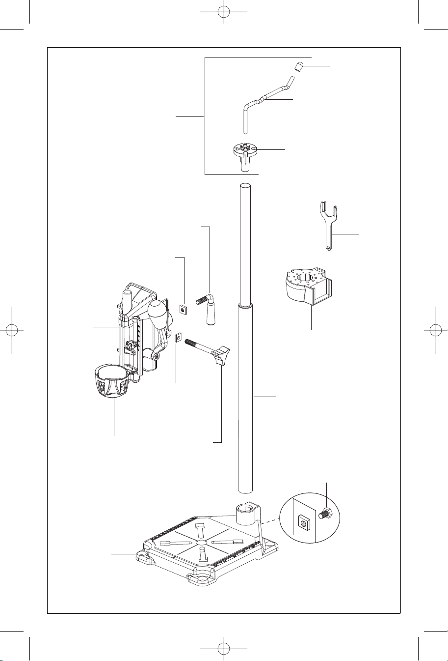
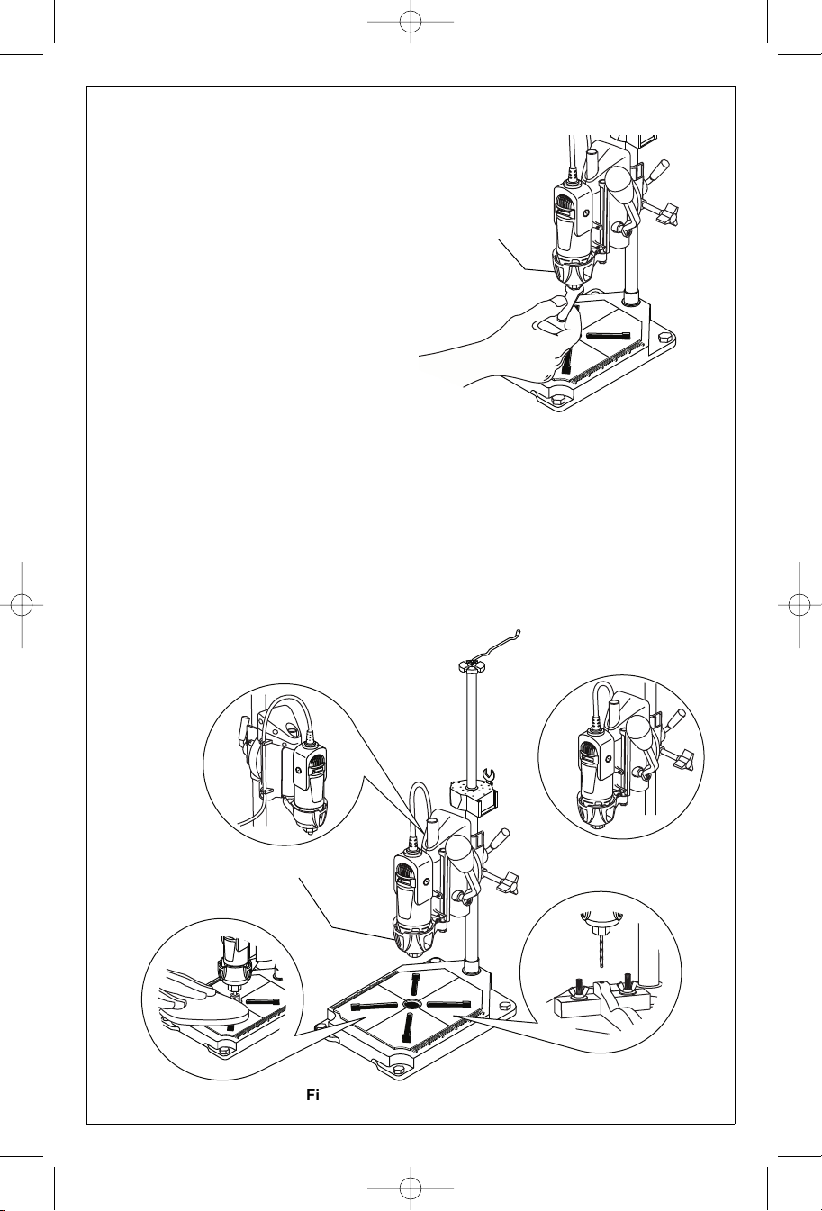
1. Assemble the tube to the base and
secure with hex bolt and square nut.
Read this entire instruction
2. Insert the square nut (short end first)
into the tube support assembly and
install the height adjustment lever. Slide
the press onto the larger section of the
tube and tighten.
3. Install the crow’s nest onto the larger
section of the tube with small holes
facing up.
4. Install the cord holder.
Install the hanger wire and cap.
5.
6. If desired, base may be secured to a
workbench using the appropriate size
hardware (not supplied).
4
Page 5
DM 2610921728 8-05E 8/23/05 9:15 AM Page 5
Cap
Drill Press
Assembly
Hanger
Height
Adjustment Lever
Square Nut
(assembled to inside of
tube support assembly)
Hanger W
Cord Holder
Crow’s Nest
ire
Wrench
Tool Holder
Base
Square Nut
(assembled to
inside of drill
press)
Angle Lock
Knob
Tube Assembly
Figure 1. Work Station 220 Components
5
Base Hex Bolt
Page 6
DM 2610921728 8-05E 8/23/05 9:15 AM Page 6
Operation
IMPORT
only one tool at time. Do not hang a tool on
hanger assembly when another tool is
mounted in the press.
The Crow’s Nest tool storage will hold the following tools:
• Drill bit set (Model 628 or 631)
• Rotary tool wrench
• Mounting wrench
• Bits with shank size less than or equal to 1/8"
• Rotary tool collets
NOTE: The drill bits are held in the tool by a
collet system. The bit may be installed before
or after the rotary tool is installed in the drill
press.
ANT!Work Station is for use with
(Models 480, 481, 482, 483)
1. Depress and hold the shaft lock button
while rotating the collet nut and shaft.
Continue to rotate the collet nut and
shaft until the lock engages and holds
the shaft (Figure 2).
2. Use the wrench from your Dremel
Rotary Tool and turn the collet nut counterclockwise to loosen it.
3. Release the shaft lock button.
Figure 2. Loosening/Tightening Collet
4. Insert the drill bit into the collet as deep
5. Re-engage the shaft lock button and tight-
Shaft Lock
Button
as possible to ensure proper gripping of
the bit and to minimize run out. Do not
insert the bit so far that the flutes touch
the collet or collet nut to avoid chipping
or cracking the bit.
en the collet nut; first by hand, then using
the wrench until bit is held securely.
Cord should be
positioned to
the side when
drill press is
used.
Clamp Nut
Figure 3. Installing Rotary Tool
6
Page 7
DM 2610921728 8-05E 8/23/05 9:15 AM Page 7
6. Remove nose cap from rotary tool.
7. Insert the rotary tool into the press with
the shaft lock to the front. Clamp the tool
to the tool bracket by tightening the clamp
nut Figure 3).
NOTE: Model 398 mounts with shaft lock to
the back and cord to the right. Models 400
and 800 mount with shaft lock to the right.
NOTE: When clamping rotary tool in holder,
make sure tool is seated properly and vent
openings are not covered.
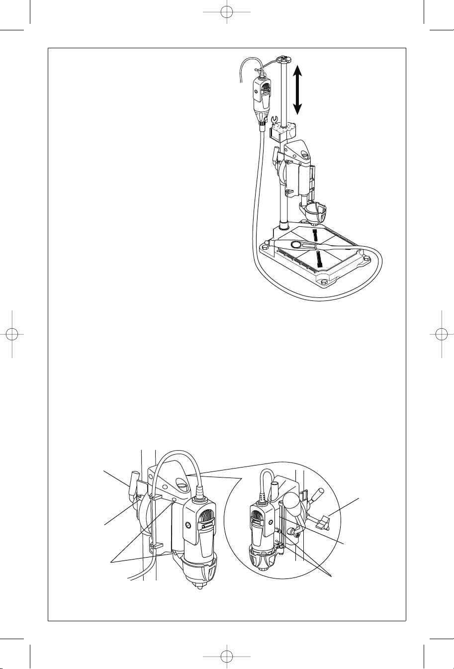
8. Twist the top tube counterclockwise to
loosen and enable the tube to be adjusted up or down. After desired height is
achieved, turn tube clockwise to tighten it
(Figure 4).
NOTE: Tube should not be extended when
tool is being used in tool holder.
Insert the cord into the cord clips (Figure
2). Holder will keep cord away from the
work area. Make sure there is sufficient
slack to keep the cord from being pulled
taut when the full stoke of the press is
used.
9. The Depth Stop is used when you wish
to drill holes to a measured depth. A
scale on the press housing is provided
for your convenience.
Set the depth stop adjustment to the
desired depth and tighten depth stop
lock knob (Figure 5). Four set screws
are also provided on the depth gauge
and left side of the housing assembly
(See Figure 5). These screws allow for
micro adjustments to the drill press. Use
1.5mm allen wrench to make adjustments. Be carefull not to overtighten set
screws.
10. The small and large Angle Lock knobs
are used to secure the tool either verti-
Height
Adjustment
Lever
urn tube counter-
T
clockwise to loosen,
adjust tube up or
down, turn tube clockwise to tighten.
NOTE: T
not be extended when
tool is being used in
tool holder.
ube should
Figure 4. Adjusting Tube Height
cally or at a 90° angle. Tool may be used
at a 15°, 30°, 45°, 60°, 75° or 90° angle
for sanding, polishing or wire wheel
application.
Loosen the large and small knobs and
rotate the tool, then securely tighten
both angle lock knobs.
11. The Height Adjustment Lever is used to
secure the press on the tube at the proper height.
Loosen the lever and move the
press/tool assembly to the desired position, then tighten the height adjustment
lever.
Large Angle
Lock Knob
Small Angle
Lock Knob
Set Screws
Depth Stop
Adjustment
Lock Knob
Set Screws
Figure 5. Setting Depth and Height Adjustments
7
Page 8
DM 2610921728 8-05E 8/23/05 9:15 AM Page 8
Operation (continued)
12. Mark the hole locations on the workpiece and center punch at these loca
tions. Center punching will prevent walking of the drill point and ensure proper
hole location. The benefits of center
punching are less drill breakage and
better hole size tolerance.
13. Secure the workpiece to the base before
drilling. This will keep the workpiece
from climbing the drill bit or spinning.
The benefit is safety and better quality
work. Hold down clamps (not included)
are very good for holding workpieces, or
use a small utility vise for holding the
workpiece when drilling (Figure 6).
14. Loosen the Height Adjustment Lock
lever 1/2 turn and move the press on the
tube until drill bit tip is near the workpiece. (A maximum of 1/4" between drill
bit tip and workpiece is recommended.)
Retighten lock lever.
15. Grasp the Press Handle and pull down
to drill hole.
-
Figure 6. Workpiece Hold Downs
Clamps (not supplied)
Figure 7. Round Workpiece
Helpful hints
When drilling round pieces, use a “V” block or
vise. To drill a hole in the center of a round
piece, a center punch mark is necessary
(Figure 7). Use center punch to make center
punch mark (not included).
Avoid force feeding to such an extent that the
motor speed is noticeably reduced. Also,
feed carefully when approaching point of
breakthrough. This will avoid making ragged
breakthrough edges.
For accurate drilling, lower the tool to a location where the end of the drill bit is within 1/4"
of the workpiece before advancing the handle for feeding the drill. Using minimum
stroke and center punching at the location to
be drilled will ensure accurate drilling.
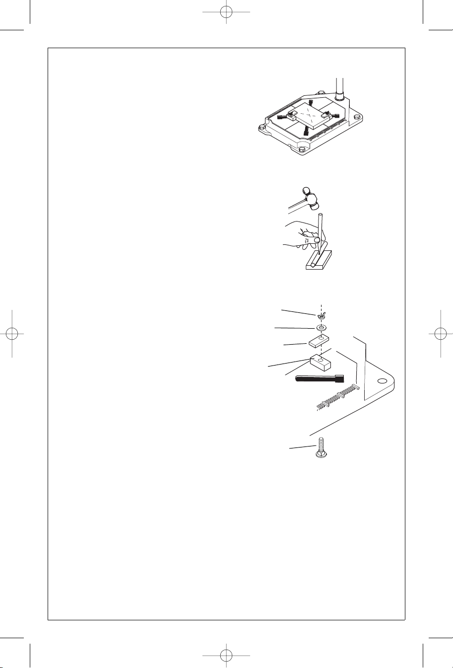
Making optional hold down clamps for
your Work Station 220
Hold down clamps can be fabricated out of
wood, steel or aluminum, depending on your
application.
1. Cut or saw material to desired length,
width and height.
2. Drill a hole using a 5/16" or 21/64" drill
bit in the desired location, through the
clamp.
3. Mount the hold down clamps using a
5/16"-18 x 1-1/2" or 2" length carriage
Wing Nut
Washer
Hold Down
Spacer
Carriage Bolt
Figure 8. Making Optional Hold
Down Clamps
bolts with matching washers and wing
nuts.
4. Mount to base by sliding the head of the
carriage bolt up through the bottom of
the base with the wing nuts on top.
When using hold down clamps on workpieces larger than 1/4" in thickness, always
use a spacer block to support the back side
of the clamp (Figure 8). For the best support,
the spacer block should be cut about 1/8"
shorter in height than the workpiece.
8
8
Page 9

DM 2610921728 8-05E 8/23/05 9:15 AM Page 9
Dremel Limited Warranty
Your Dremel product is warranted against defective material or workmanship for a period of
one year from date of purchase. In the event of a failure of a product to conform to this written warranty, please take the following action:
1. DO NOT return your product to the place of purchase.
2. Carefully package the product by itself, with no other items, and return it, freight prepaid,
along with:
A. A copy of your dated proof of purchase (please keep a copy for yourself).
B. A written statement about the nature of the problem.
C. Your name, address and phone number to:
UNITED STATES
Dremel Service Center Dremel Service Center
4915 21st Street OR 4631 E. Sunny Dune
Racine, WI 53406 Palm Springs, CA 92264
CANADA OUTSIDE
Giles Tool Agency CONTINENTAL UNITED STATES
6520 Lawrence Av. East See your local distributor or write to
Scarborough, Ont Dremel, 4915 21st Street
Canada M1C 4A7 Racine, WI 53406
We recommend that the package be insured against loss or in transit damage for which we
cannot be responsible.
This warranty applies only to the original registered purchaser. DAMAGE TO THE PRODUCT RESULTING FROM TAMPERING, ACCIDENT, ABUSE, NEGLIGENCE, UNAUTHORIZED REPAIRS OR ALTERATIONS, UNAPPROVED ATTACHMENTS OR OTHER
CAUSES UNRELATED TO PROBLEMS WITH MATERIAL OR WORKMANSHIPARE NOT
COVERED BY THIS WARRANTY.
No employee, agent, dealer or other person is authorized to give any warranties on behalf
of Dremel. If Dremel inspection shows that the problem was caused by problems with material or workmanship within the limitations of the warranty, Dremel will repair or replace the
product free of charge and return product prepaid. Repairs made necessary by normal
wear or abuse, or repair for product outside the warranty period, if they can be made, will
be charged at regular factory prices.
DREMEL MAKES NO OTHER WARRANTY OF ANY KIND WHATEVER, EXPRESSED OR
IMPLIED, AND ALL IMPLIED WARRANTIES OF MERCHANTABILITY AND FITNESS FOR A
PARTICULAR PURPOSE WHICH EXCEED THE ABOVE MENTIONED OBLIGATION ARE
HEREBY DISCLAIMED BY DREMEL AND EXCLUDED FROM THIS LIMITED WARRANTY.
This warranty gives you specific legal rights and you may also have other rights which vary
from state to state. The obligation of the warrantor is solely to repair or replace the product. The
warrantor is not liable for any incidental or consequential damages due to any such alleged
defect. Some states do not allow the exclusion or limitation of incidental or consequential damages, so the above limitations or exclusion may not apply to you.
For prices and warranty fulfillment in the continental United States, contact your local Dremel
distributor.
9
Page 10
DM 2610921728 8-05E 8/23/05 9:15 AM Page 10
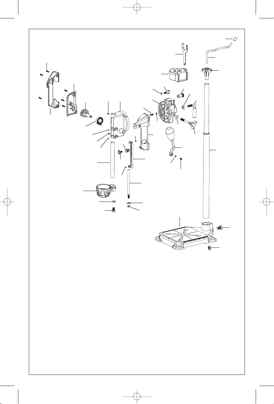
Parts Diagram
1
3
7
6b
6a
8
10
11
asher
6b
16
15
6a
Assembly
4
2
5
6a
9
Ref. Part No. Description
1 2610921769 Screw (6)
2 2610929316 Outer Shell-Left
3 2610928604 Housing Cover
4 2610930418 Pinion
5 2610928594 Torsion Spring
6a 2610933097 Small Set Screw (4)
6b 2610935514 Large Set Screw (2)
7 2610928605 Main Housing
8 2610928596 Rack
9 2610928607 Tool Holder
10 2610921755 Washer
11 2610921738 Hex Bolt
12 2610921768 Hex Nut
2610921767
13
14 2610921766 Depth Rod
15 2610933108 Knob
16 2610928717 Stop piece
17 2610928598 Depth Gauge
18 2610933939 Screw
19 2610933107 Washer
20 2610928597
21 2610921716 Angle Lock Knob
22 2610923737 Square Nut
23 2610929317 Outer Shell Right
24 2610921756 Screw
W
Handle
28
27
25
39
26
32
33
34
24
6a
25
23
22
21
20
17
19
18
14
13
12
Ref. Part No. Description
25 2610921980 Washer (2)
26 2610921749 Wing Knob
27 2610921722 Crow’s Nest
28 2610917207 Wrench
29 2615297527 Grommet
30 2615297529 Hanger
31 2610923471 Cord Holder
32 2610921746 Pin
2610921747 Square Nut
33
34 2610921719 Height Adjustment
35 2610921736 Extension Tube
36 2610921732 Hex Bolt
2610
37
2610921710
38
39 2610921745 Shaft Support
101010
38
921731
Assembly
Assembly
Square Nut
Assembly
Base
29
30
31
35
36
37
Page 11

DM 2610921728 8-05E 8/23/05 9:15 AM Page 11
NOTES
11
Page 12

Mode d'emploi
Table des Matières
Consignes de sécurité pour les outils
Électroportatifs . . . . . . . . . . . . . . . . .13 - 14
Consignes de sécurité pour les Perceuses
Sensitives . . . . . . . . . . . . . . . . . . . .14 - 15
Assemblage . . . . . . . . . . . . . . . . . . . .16 - 17
Utilisation . . . . . . . . . . . . . . . . . . . . . .18 - 21
Garantie . . . . . . . . . . . . . . . . . . . . . . . . . . .22
Schéma des Pièces . . . . . . . . . . . . .23 - 24
Habla español? Ver página . . . . . . . . . .25
¿
Poste de Travail
MODÈLE 220
4915 21st Street
Racine, WI 53406
1-800-437-3635
http://www.dremel.com
Page 13

Règles de Sécurité Générales
!
AVERTISSEMENT
d'incendie et/ou de blessures graves.
Veillez à ce que l'aire de travail soit propre
et bien éclairée. Le désordre et le manque
de lumière favorisent les accidents.
N'utilisez pas d'outils électriques dans
une atmosphère explosive, par exemple
enprésence de liquides, de gaz ou de
poussières inflammables. Les outils élec-
triques créent des étincelles qui pourraient
enflammer les poussières ou les vapeurs.
Tenez à distance les curieux, les enfants
et les visiteurs pendant que vous travaillezavec un outil électrique. Ils pour-
raient vous distraire et vous faire faire une
fausse manoeuvre.
Sécurité Électrique
Les outils à double isolation sont équipés
d'une fiche polarisée (une des lames est
pluslarge que l'autre), qui ne peut se
brancher que d'une seule façon dans une
prise polarisée. Si la fiche n'entre pas parfaitement dans la prise, inversez sa position ; si elle n'entre toujours pasbien,
demandez à un électricien qualifié d'installer une prise de courant polarisée. Ne
modifiez pas la fiche de l'outil. La double
isolation élimine le besoin d'un cordon
d'alimentationà trois fils avec mise à la terre
ainsi que d'une prise de courant mise à la
terre. Avant de brancher l'outil, assurez-vous
que la tension de la prise correspond, à celle
indiquée sur la plaque signalétique. N'utilisez
pas d'outils prévus pour courant alternatif
seulement avec une source de courant
continu.
Évitez tout contact corporel avec des surfaces mises à la terre (tuyauterie, radiateurs, cuisinières, réfrigérateurs, etc.). Le
risque de choc électrique est plus grand si
votre corps est encontact avec la terre.Si l'utilisation de l'outil électrique dans un endroit
humide est inévitable, un disjoncteur de fuite
à la terre doit être utilisé pour alimenter votre
outil. Des chaussures et des gants en
caoutchouc d'électricien contribueront à
accroître davantage votre sécurité
personnelle.
N'exposez pas les outils électriques à la
pluie ou à l'eau. La présence d'eau dans un
outil électrique augmente le risque de choc
électrique.
Ne maltraitez pas le cordon. Ne transportez pas l'outil par son cordon et ne
débranchez pas la fiche en tirant sur le
Vous devez lire et comprendre toutes les instructions. Lenon-respect,
même partiel, des instructions ci-après entraîne un risque de choc életrique,
CONSERVEZ CES INSTRUCTIONS
Aire de Travail
cordon. N'exposez pas le cordon à la
chaleur, à des huiles, à des arêtes vives
ou à des pièces en mouvement.
Remplacez immédiatement un cordon
endommagé. Un cordon endommagé aug-
mente le risque de choc électrique.
Lorsque vous utilisez un outil électrique à
l'extérieur, employez un prolongateur
pour l'extérieur marqué « W-A » ou « W ».
Ces cordons sont faits pour être utilisés à
l'extérieur et réduisent le risque de choc électrique. Reportez-vous aux Dimensions
recommandées des cordons de rallonge »
dans la section Accessoires de ce manuel.
Sécurité des Personnes
Restez alerte, concentrez-vous sur votre
travail et faites preuve de jugement.
N'utilisez pas un outil électrique si vous
êtes fatigué ou sous l'influence de
drogues, d'alcool ou de médicaments. Un
instant d'inattention suffit pour entraîner des
blessures graves.
Habillez-vous convenablement. Ne portez
ni vêtements flottants ni bijoux. Confinez
les cheveux longs. N'approchez jamais
les cheveux, les vêtements ou les gants
des pièces en mouvement. Des vêtements
flottants, des bijoux ou des cheveux longs
risquent d'être happés par des pièces en
mouvement. Gardez les poignées sèches,
propres et exemptes d'huile et de graisse.
Méfiez-vous d'un démarrage accidentel.
Avant de brancher l'outil, assurez-vous
que son interrupteur est sur ARRÈT.
fait de transporter un outil avec le doigt sur la
détente ou de brancher un outil dont l'interrupteur est en position MARCHE peut mener
tout droit à un accident.
Enlevez les clés de réglage ou de serrage
avant de démarrer l'outil. Une clé laissée
dans une pièce tournante de l'outil peut
provoquer des blessures.
Ne vous penchez pas trop en avant.
Maintenez un bon appui et restez en
équilibre entout temps. Un bonne stabilité
vous permet de mieux réagir à une situation
inattendue.
Utilisez des accessoires de sécurité.
Portez toujours des lunettes ou une
visière. Selon les conditions, portez aussi un
masque antipoussière, des bottes de sécurité antidérapantes, un casque protecteur
et/ou un appareil antibruit.
Le
13
Page 14

Utilisation et Entretien des Outils
Immobilisez le matériau sur une surface
stable au moyen de brides ou de toute
autre façon adéquate.
pièce avec la main ou contre votre corps
offre une stabilité insuffisante et peut amener
un dérapage de l'outil.
Ne forcez pas l'outil. Utilisez l'outil approprié à la tâche. L'outil correct fonctionne
mieux et de façon plus sécuritaire.
Respectez aussi la vitesse de travail qui lui
est propre.
N'utilisez pas un outil si son interrupteur
est bloqué. Un outil que vous ne pouvez pas
commander par son interrupteur est dangereux et doit être réparé.
Débranchez la fiche de l'outil avant d'effectuer un réglage, de changer d'accessoire oude ranger l'outil. De telles mesures
préventives de sécurité réduisent le risque
de démarrage accidentel de l'outil.
Rangez les outils hors de la portée des
enfants et d'autres personnes inexpérimentées. Les outils sont dangereux dans les
mains d'utilisateurs novices.
Prenez soin de bien entretenir les outils.
Les outils de coupe doivent être toujours
bien affûtés et propres. Des outils bien
entretenus, dont les arêtes sont bien tranchantes, sont moins susceptibles de coincer
et plus faciles à diriger.Toute altération ou
modification constitue un usage erroné et
peut causer un danger.
Soyez attentif à tout désalignement ou
coincement des pièces en mouvement, à
Le fait de tenir la
tout bris ou à toute autre condition préjudiciable au bon fonctionnement de l'outil.
Si vous constatez qu'un outil est endommagé, faites-le réparer avant de vous en
De nombreux accidents sont causés
servir.
par des outils en mauvais état. Élaborez un
calendrier d'entretien périodique de votre
outil.
N'utilisez que des accessoires que le fabricant recommande pour votre modèle
d'outil. Certains accessoires peuvent con-
venir à un outil, mais être dangereux avec un
autre.
Réparation
La réparation des outils électriques doit
être confiée à un réparateur qualifié.
L'entretien ou la réparation d'un outil électrique par un amateur peut avoir des conséquences graves. Ainsi, des fils internes
peuvent être mal placés ou pincés, des
ressorts de rappel de protecteur peuvent être
montés erronément.
Pour la réparation d'un outil, n'employez
que des pièces de rechange d'origine.
Suivez les directives données à la section
« Réparation » de ce manuel. L'emploi de
pièces non autorisées ou le non-respect des
instructions d'entretien peut créer un risque
de choc électrique ou de blessures. Certains
agents nettoyants tels qu'essence, tétrachlorure de carbone, ammoniac, etc., peuvent abîmer les pièces en plastique.avant
l’entretien ; avant de changer les lames, les
mèches, les couteaux, etc.
Consignes de Sécurité pour les outils Électroportatifs
Débranchez l'outil avant de le monter sur
une table, de faire des réglages ou de
changer d'embout.
en cas de démarrage intempestif de l'outil.
Fixez fermement la table sur une plateforme ou un établi stable.
bilité pendant l'utilisation, la plate-forme ou
l'établi risque de bouger ou de basculer causant ainsi une perte de contrôle et des
blessures.
Fixez fermement l'outil à la table avant
utilisation.
tilisation il aura tendance à sortir tout seul de
la bride et il risque de tomber avec l'embout
toujours en rotation.
Sachez arrêter votre outil! Positionnez-le
de manière à ce que l'interrupteur soit facile
ment accessible pour pouvoir arrêter l'outil
rapidement en cas d'urgence.
Éloignez le cordon de l'embout et de la
zone de coupe.
Si l'outil se desserre pendant l'u-
Il y a risque de blessure
En cas d'insta-
Il y a risque de choc,
brûlure ou électrocution si on coupe un cordon sous tension.
Portez une protection oculaire et un
masque à poussière.
dans un endroit bien ventilé. L'utilisation
d'équipements de protection personnelle et
le fait de travailler dans un endroit sûr
réduisent le risque de blessures.
Ne pas porter de gants, de cravate ou de
vêtements amples quand vous utilisez
l’outil.
Nouer les cheveux longs ou utiliser
un filet à cheveux. Les vêtements ou les
cheveux risquent d’être happés par le foret
(ou fer) en rotation, ce qui pourrait résulter
en blessures.
Le type et la vitesse de l'embout doivent
-
être adaptés à la tâche. N'utilisez pas
d'embouts dont le diamètre de coupe
dépasse la capacité de l'outil.
perceuse sensitive est prévu principalement
pour effectuer de travaux légers dans du
14
Utilisez uniquement
Le pied de
Page 15

Consignes de Sécurité pour les outils Électroportatifs (suite)
bois. Si on surcharge l'outil, il y a risque de
blessure corporelle ou de panne.
Il ne faut jamais utiliser d'embouts
abîmés ou émoussés. Soyez prudents
quand vous manipulez des embouts
affûtés.
casser pendant l'utilisation. Les embouts
émoussés nécessitent plus d'effort pour
pénétrer dans la pièce, ce qui risque
éventuellement de les casser.
Assurez-vous que la pièce ne contient ni
clous ni autres objets étrangers.
coupez un clou, vous abîmerez l'embout et la
pièce risque de rebondir et de causer une
perte de contrôle.
Avant utilisation, bridez la pièce ou
appuyez-la contre la colonne. Il ne faut
jamais tenir une petite pièce dans une
main et abaisser la perceuse.
pièce vous permet d'utiliser les deux mains
pour mieux maîtriser l'outil. Fixer la pièce
l'empêche de tourner ou d'être avalée par
l'embout pendant le perçage.
Utilisez un vé pour supporter les pièces
rondes telles que les tubes ou les tiges
pendant le perçage.
telles que les goujons, les tuyaux ou les
tubes ont tendance à rouler pendant la
coupe. L'embout risque ainsi de mordre
dans la pièce ou la pièce risque de rebondir
vers vous.
Il faut régler la tête de l'outil et la profondeur de coupe à la position désirée et
l'y fixer quand vous effectuez des
opérations autres que le perçage.
Amenez la pièce à l'outil et laissez
suffisamment d'espace entre votre main
et l'embout en rotation (au moins 150 mm
(6 po).
rotation, vous vous blesserez.
Cette perceuse à colonne a été conçue pour
des opérations de perçage, de ponçage, de
brossage, de polissage et de meulage. Son
utilisation dans des opérations autres que
celles-ci risque de présenter des dangers
inévitables.
Si le côté d’un
rotation, un tambour de ponçage par exemple,
est utilisé pour réaliser le travail, il faut faire
avancer la pièce sur le côté de l’accessoire
qui tourne en direction opposée au sens
d’avance de la pièce. Le fait de faire avancer
la pièce sur le côté de l’accessoire qui tourne
dans la même direction que le sens d’avance
Les embouts abîmés risquent de
Si vous
Brider la
Les pièces rondes
Si vous touchez l'embout en
quelconque accessoire en
de la pièce risque de causer l’entraînement
de la pièce par l’accessoire en rotation et de
mener à une perte de contrôle pendant
l’opération.
Ne démarrez jamais l'outil avec l'embout
engagé dans le matériau.
l'embout risque de happer la pièce et de
causer une perte de contrôle.
N'approchez pas les mains de la zone du
fer en rotation.
que votre main est proche de l'embout en
rotation. La pièce risque de bouger ou votre
main risque de glisser pendant l'utilisation.
!
AVERTISSEMENT
ou le perçage à la machine ainsi que
d'autres activités du bâtiment produisent
certaines poussières qui contiennent des
produits chimiques, lesquels peuvent
causer des cancers, des déformations
congénitales ou d'autres troubles
reproductifs. Ces produits chimiques sont
par exemple :
• Le plomb provenant des peintures à base
de plomb ;
• Les cristaux de silice provenant des
briques, du ciment et d'autres produits de
maçonnerie et
• L'arsenic et le chrome provenant des bois
traités chimiquement.
Après avoir changé d'embout ou effectué
un réglage, assurez-vous que l'écrou de
douille ainsi que tous les autres dispositifs de réglage sont fermement serrés.
Les dispositifs de réglage mal serrés risquent
de bouger de manière inattendue, résultant
en une perte de contrôle. Toute pièce en
rotation mal serrée sera éjectée violemment.
Il ne faut jamais toucher l'embout pendant
ou immédiatement après utilisation.
vous touchez l'embout en rotation, vous vous
blesserez. Après utilisation, l'embout est trop
chaud pour qu'on puisse le toucher à mains
nues.
Ne laissez pas un outil en rotation sans
surveillance. Arrêtez-le.
sécurité, attendez l'arrêt complet de l'embout
avant d'enlever la pièce et de nettoyer le pied
de perceuse.
PENSEZ À LA
résulte du BON SENS et de la VIGILANCE
constante de l'utilisateur pendant utilisation
de l'outil.
Il n'est pas toujours évident
SÉCURITÉ!
Le tranchant de
Le ponçage, le
sciage, le meulage
Si
Pour votre
La sécurité
15
Page 16

Assemblage
CET ACCESSOIRE CONVIENT AUX OUTILS ROTATIFS DREMEL MODELES 275,
285, 295, 300, 398, 400, 780 ET 800.
ATTENTION:
entièrement et attentivement avant d'utiliser
votre poste de travail Dremel. Conservez ces
instructions pour vous y reporter ultérieurement. Votre poste de travail Dremel 220 permet de convertir des outils rotatifs en
perceuse sensitive pour percer. Il peut
également servir de porte-outil pour poncer
ou polir ou même de pied pour outil muni
d'un arbre flexible.
1. Assemblez le tube sur le socle et fixezle avec le boulon 6 pans et l'écrou carré.
Veuillez lire ce mode d'emploi
2. Enfoncez l'écrou carré (bout court en premier) dans le support d’ensemble du
tube et installez la manette de réglage
de la hauteur. Faites glisser le coulisseau sur la section la plus large du tube
et serrez.
3. Installez le porte-embout sur la section la
plus large du tube avec les petits trous
tournés vers le haut.
4. Installez la pince du cordon.
5. Installez le crochet en métal et son
capuchon.
6. Si on le désire, on peut fixer le socle sur
un établi à l'aide de vis de taille appropriée (non fournies).
16
Page 17

Ensemble du crochet
Manette
de Réglage de la
hauteur
Écrou Carré
(Assemblé à l’intérieur du support
d’ensemble du tube)
Capuchon
Crochet en métal
Pince du cordon
Clé
Coulisseau
Porte-outil
Socle
Écrou Carré
(assemblé à l'intérieur
du coulisseau)
Bouton de
blocage de
l'angle
Figure 1. Poste de T
ravail Mod
17
Porte-embout
Ensemble du tube
le 220 Composant
è
Boulon 6 pans
du socle
Page 18

Utilisation
IMPORT
utilisé qu'avec un seul outil à la fois. Il ne faut
pas accrocher un outil sur le crochet quand
un autre outil est monté sur le coulisseau.
Le porte-embout permet de ranger les outils
suivants :
• Jeu de forets (Modèle 628)
• Clé de l'outil rotatif
• Clé de montage
• Embouts avec queue d'un diamètre
inférieur ou égal à 1/8 po
• Douilles pour l'outil rotatif
(Modèles 480, 481, 482, 483)
REMARQUE: Les embouts rotatifs sont
retenus dans l'outil par un système de douille.
On peut installer l'embout soit avant soit
après avoir installé l'outil rotatif sur le pied de
perceuse sensitive.
1. Appuyez sur le bouton de blocage de l'arbre et maintenez-le enfoncé tout en tournant l'écrou de douille et l'arbre.
Continuez de tourner l'écrou de douille et
l'arbre jusqu'à ce que le blocage s'enclenche et bloque l'arbre (Figure 2).
2. À l'aide de la clé fournie avec votre outil
rotatif Dremel, tournez la douille en sens
anti-horaire pour la desserrer.
Le poste de travail ne peut être
ANT!
Bouton de
blocage de
l'arbre
Figure 2. Desserrage/ serrage
de la Douille
3. Lâchez le bouton de blocage de l'arbre.
4. Enfoncez le foret dans la douille aussi loin
que possible afin de pouvoir le pincer correctement et de minimiser le battement.
N'enfoncez pas le foret si profond que les
cannelures touchent la douille ou l'écrou
de douille afin d'éviter de l'ébrécher ou de
le fêler.
5. Ré-enclenchez le bouton de blocage de
l'arbre et serrez l'écrou de douille, d'abord
à la main puis avec la clé jusqu'à ce que
le foret soit maintenu fermement.
Il faut positionner le
cordon sur le
côté quand
on utilise la
perceuse
sensitive.
Écrou de pince
Figure 3. Montage de l'outil Rotatif
18
Page 19

Utilisation (suite)
6. Retirez le capuchon de l’outil rotatif.
7. Insérez l’outil rotatif dans le coulisseau
avec le blocage de l'arbre dirigé vers
l'avant. Bridez l'outil dans la pince du
porte-outil en serrant l'écrou de la pince.
REMARQUE : le modèle 398 se monte avec
le blocage de l’arbre à l’arrière et le cordon à
droite. Les modèles 400 et 800 se montent
avec le blocage de l’arbre à droite.
REMARQUE: Quand vous serrez l'outil rotatif
dans le porte-outil, assurez-vous qu'il est assujetti correctement et que les ouïes de ventilation ne sont pas masquées.
8. Faites pivoter le tube supérieur en sens
anti-horaire pour le desserrer, ce qui permet de le régler vers le haut ou vers le bas.
Quand vous avez atteint la hauteur
désirée, tournez le tube en sens horaire
pour le serrer (Figure 4).
REMARQUE: Il ne faut pas déployer le tube
quand l'outil est monté dans le porte-outil.
Enfoncez le cordon dans la pince du cordon (Figure 2), ce qui le maintient éloigné
de la zone de travail. Assurez-vous qu'il y
a assez de mou dans le cordon pour qu'il
ne soit pas tendu quand la perceuse sensitive est en bout de course.
9. Utilisez la butée de profondeur quand vous
voulez percer des trous d'une profondeur
donnée. Le boîtier du coulisseau est muni
d'une échelle pour vous faciliter la tâche.
Réglez la butée de profondeur à la profondeur désirée et serrez le bouton de
blocage de la profondeur (Figure 5).
Quatre vis de pression sont également
fournies sur l’échelle de profondeur et le
côté gauche du boîtier (cf. figure 5). Ces vis
permettent le microréglage du coulisseau.
Utilisez une clé Allen de 1,5 mm pour
effectuer les réglages. Faites attention de
ne pas trop serrer les vis de pression.
Manette de
Réglage
de la Hauteur
Bouton de
verrouillage des
petits angles
Vis de
pression
Figure 5. Réglage de la Profondeur et de la Hauteur
ournez le tube en sens
T
anti-horaire pour le
desserrer, réglez le tube
vers le haut ou vers le bas,
tournez le tube en sens
horaire pour le serrer.
REMARQUE: Il ne faut pas
déployer le tube quand
l'outil est monté dans le
porte-outil.
Figure 4. Réglage de la hauteur du tube
10. Les boutons de verrouillage des petits
angles et des grands angles servent à
fixer l’outil soit dans la position verticale,
soit à un angle de 90 °. L'outil peut
être utilisé à 15°, 30°, 45°, 60°, 75° ou
90° pour poncer, pour polir ou pour le
travail à la brosse métallique.
Desserrez le petit bouton et le grand
bouton et faites pivoter l'outil puis
resserrez fermement les deux boutons
de blocage de l'angle.
11. Utilisez la manette de réglage de hauteur pour bloquer le coulisseau sur le
tube à la hauteur appropriée.
Bouton de
verrouillage
des grands
angles
Bouton de
Blocage de la
butée de
Profondeur
Vis de
pression
19
Page 20

Desserrez la manette et déplacez
l'ensemble du coulisseau et de l'outil
pour l'amener à la position désirée puis
resserrez la manette de réglage de la
hauteur.
12. Repérez la position des trous sur la
pièce et marquez les centres d'un coup
de pointeau, ce qui empêchera la pointe
du foret de glisser et assurera que le
trou est percé au bon endroit. Les avantages du coup de pointeau sont un
moindre risque de casser le foret et une
meilleure précision dans le diamètre du
trou.
13. Fixez la pièce sur le socle avant de
percer. Ceci évitera qu'elle soit avalée
par le foret ou qu"elle tourne avec lui.
L'avantage du bridage est l'amélioration
de la sécurité et de la qualité. Des
brides (non fournies) conviennent
parfaitement mais vous pouvez
également utiliser un petit étau pour
tenir la pièce lors du perçage (Figure 6).
14.Desserrez le levier de blocage du
réglage de la hauteur d'un 1/2 tour et
déplacez le coulisseau le long du tube
afin d'amener la pointe du foret à proximité de la pièce. (On recommande un
maximum de 1/4 po entre la pointe du
foret et la pièce) Resserrez le levier de
blocage.
15.Saisissez le levier du coulisseau
et abaissez-le pour percer le trou.
Figure 6. Brides de Pièces
(non fournies)
Figure 7. Pièce Ronde
Conseils Utiles
Pour percer dans des pièces rondes, utilisez
un vé ou un étau. Pour percer un trou au centre d'une pièce ronde, il est nécessaire d'en
marquer le centre d'un coup de pointeau
(Figure 7). (Pointeau non compris).
Évitez de forcer au point où la vitesse du
moteur est réduite de matière notable. Il faut
également pousser doucement quand le
foret est prêt à déboucher. Cela évitera de
déchiqueter le bord du trou quand on
débouche.
Pour améliorer la précision du perçage,
abaissez l'outil de manière à amener la
pointe du foret à 1/4 po ou moins de la pièce
avant d'abaisser le levier qui fait avancer le
foret. La précision du perçage sera assurée
si on minimise la course et si on marque le
centre du trou d'un coup de pointeau là où on
désire percer.
20
Page 21

Fabrication de Brides Optionnelles pour
votre Poste de Travail 220
On peut fabriquer les brides en bois, en
aluminium ou en acier suivant la tâche à
effectuer.
1. Coupez ou sciez la pièce à la longueur,
largeur et hauteur désirées.
2. Percez un trou débouchant dans la bride
à l'aide d'un foret de 5/16 po ou de 21/64
po à l'endroit désiré.
3. Montez les brides à l'aide de boulons de
carrosserie de 5/16 -18 x 1-1/2 po ou 2
po de long et de rondelles et écrous
papillon correspondants.
4. Montez-les sur le socle en glissant la
tête du boulon de carrosserie par le
dessous du socle avec les écrou-papillons
sur le dessus.
Quand on utilise les brides sur des pièces
d'épaisseur supérieure à 1/4 po, il faut toujours placer une cale d'épaisseur pour supporter l'arrière de la bride (Figure 8). Pour
supporter la bride au mieux, il convient de
couper la cale épaisseur environ 1/8 po plus
court que la hauteur de la pièce.
Écrou à ailettes
Rondelle
Bride
Cale
Boulon
de carrosserie
Figure 8. Fabrication de Brides
en Option
21
Page 22

Garantie limitée de Dremel
Votre produit Dremel est garanti contre les vices de matière et de main d'œuvre pour une période
de d'un an à partir de la date d'achat. Au cas ou un produit n'est pas conforme à cette garantie
écrite, il convient d'agir comme suit :
1. NE rapportez PAS votre produit là où vous l'avez acheté.
2. Emballez le produit seul avec soin, sans rien d'autre, et renvoyez-le en port payé accompagné des documents suivants:
A. Une copie de votre preuve d'achat datée (veuillez conserver une copie pour vous-même).
B. Une description écrite du problème.
C. Votre nom, adresse et numéro de téléphone à l'attention de:
ÉTATS-UNIS
Dremel Service Center Dremel Service Center
4915 21st Street OU 4631 E. Sunny Dune
Racine, WI 53406 Palm Springs, CA 92264
CANADA EN DEHORS DES ÉTATS AMÉRICAINS
Giles Tool Agency CONTINENTAUX
6520 Lawrence Av. East Contactez votre distributeur local
Scarborough, Ont ou écrivez à
Canada M1C 4A7 Dremel, 4915 21st Street
Nous vous recommandons d'assurer votre envoi contre la perte ou les dégâts de transport,
lesquels ne peuvent en aucun cas engager notre responsabilité.
Cette garantie ne s'applique qu'à l'acheteur inscrit d'origine. LES DÉGÂTS AU PRODUIT
RÉSULTANT DE MODIFICATIONS, D'ACCIDENT, D'UN MAUVAIS TRAITEMENT, D'UNE
NÉGLIGENCE, DE RÉPARATIONS NON AUTORISÉES, DE L'UTILISATION D'ACCESSOIRES
NON HOMOLOGUÉS OU D'AUTRES CAUSES NON LIÉES À DES VICES DE MATIÈRE OU
DE MAIN D'OEUVRE NE SONT PAS COUVERTS PAR CETTE GARANTIE.
Aucun employé, agent ou distributeur ni qui que ce soit d'autre n'est autorisé à donner aucune
garantie de la part de Dremel. Si l'inspection par Dremel démontre que le problème a été causé
par un vice de matière ou de main d'œuvre dans les limites de la garantie, Dremel réparera ou
remplacera le produit sans frais et le renverra en port payé. Les réparations nécessitées par
l'usure normale ou un mauvais traitement et les réparations du produit en dehors de la période
de garantie, si elles sont possibles, seront effectuées au coût usine normal.
DREMEL NE FAIT AUCUNE AUTRE GARANTIE D'AUCUNE SORTE, EXPLICITE OU IMPLICITE,
ET TOUTES LES GARANTIES IMPLICITES QUE LE PRODUIT EST COMMERCIALISABLE ET
QU'IL CONVIENT À UN USAGE PARTICULIER SAUF COMME EXPRESSÉMENT MENTIONNÉ
CI-DESSUS SONT EXPRESSÉMENT DÉCLINÉES ET EXCLUES DE CETTE GARANTIE
LIMITÉE.
Cette garantie vous donne des droits spécifiques et il se peut que vous ayez d'autres recours légaux
qui varient d'état à état. Le devoir du garant se limite à la réparation ou au remplacement du produit. Le garant ne saurait être tenu pour responsable des dommages directs ou indirects causés par
le vice supposé. Certains états n'admettent pas l'exclusion ou la limitation des dommages directs ou
indirects. Les limitations ou exclusions mentionnées ci-dessus ne s'appliquent donc pas forcément
à vous.
Pour vous renseigner sur les prix ou l'exécution de la garantie dans les états américains continentaux, contactez votre distributeur Dremel.
Racine, WI 53406
22
Page 23

Schéma des pièces
29
1
3
4
6b
7
2
5
6a
6b
16
6a
8
15
6a
9
10
11
Ref. No. de piece Description
1 2610921769 Vis (6)
2 2610929316 Coque extérieure –
3 2610928604 Couvercle de boîtier
4 2610930418 Pignon
5 2610928594 Ressort de torsion
6a 2610933097 Petite vis de pression (4)
6b 2610933514 Grande vis de pression (2)
7 2610928605 Boîtier principal
8 2610928596 Support
9 2610928607 Porte-outil
10 2610921755 Rondelle
11 2610921738 Boulon 6 pans
12 2610921768 Écrou 6-pans
13 2610921767 Rondelle
14 2610921766 Tige de profondeur
15 2610933108 Bouton
16 2610928717 Pièce de butée
17 2610928598 Échelle de profondeur
18 2610933939 Vis
19 2610933107 Rondelle
20 2610928597 Ensemble de poignée
21 2610921716 Bouton de blocage
22 2610923737 Écrou carré
23 2610929317 Coque extérieure –
côté gauche
de l'angle
côté droit
28
27
26
25
32
33
34
25
24
22
6a
23
21
20
17
19
18
14
13
12
Ref. No. de piece Description
24 2610921756 Vis
25 2610921980 Rondelle (2)
26 2610921749 Bouton à ailettes
27 2610921722 Porte-embouts
28 2610917207 Clé
29 2615297527 Capuchon
30 2615297529 Crochet
31 2610923471 Pince pour cordon
32 2610921746 Goupille
33 2610921747 Écrou carré
2610921719
34
2610921736 Ensemble de tube de
35
2610921732 Boulon 6 pans
36
2610921731 Écrou carré
37
38 2610921710 Ensemble de socle
39 2610921745 Support d’arbre
23
38
Ensemble de réglage
de la hauteur
rallonge
30
31
35
36
37
Page 24

REMARQUES
24
Page 25

Manual del Usuario
Contenido del Manual
Normas de seguridad para Herramientas
Mecánicas . . . . . . . . . . . . . . . . . . . . .26 - 27
Normas de Seguridad para el Taladro de
Columna . . . . . . . . . . . . . . . . . . . . . .27 - 28
Montaje . . . . . . . . . . . . . . . . . . . . . . .29 - 30
Utilización . . . . . . . . . . . . . . . . . . . . .31 - 34
Garantía . . . . . . . . . . . . . . . . . . . . . . . . . . .35
Diagrama de Piezas . . . . . . . . . . . . .36 - 37
Parlez-vous français? Voir page . . . . . .12
Estación de Trabajo
MODELO 220
4915 21st Street
Racine, WI 53406
1-800-437-3635
http://www.dremel.com
Page 26

Normas de seguridad para Herramientas Mecánicas
!
ADVERTENCIA
tricas, incendios y/o lesiones personales graves.
Lea y entienda todas las instrucciones. El incumplimiento de todas las
instrucciones indicadas a continuación puede dar lugar a sacudidas eléc-
CONSERVE ESTAS INSTRUCCIONES
Area de Trabajo
Mantenga el área de trabajo limpia y bien
iluminada. Las mesas desordenadas y las
áreas oscuras invitan a que se produzcan
accidentes.
No utilice herramientas mecánicas en
atmósferas explosivas, tales como las
existentes en presencia de líquidos,
gases o polvos inflamables. Las
herramientas mecánicas generan chispas y
éstas pueden dar lugar a la ignición del polvo
o los vapores.
Mantenga a las personas que se
encuentren presentes, a los niños y a los
visitantes alejados al utilizar una
herramienta mecánica. Las distracciones
pueden hacer que usted pierda el control.
Seguridad Eléctrica
Las herramientas con aislamiento doble
están equipadas con un enchufe
polarizado (un terminal es más ancho que
el otro). Este enchufe entrará en un
tomacorriente polarizado solamente de
una manera. Si el enchufe no entra por
completo en el tomacorriente, déle la
vuelta. Si sigue sin entrar, póngase en
contacto con un electricista competente
para instalar un tomacorriente polarizado.
No haga ningún tipo de cambio en el
enchufe. El aislamiento doble elimina la
necesidad del sistema de cordón de energía
de tres hilos conectado a tierra y la fuente de
energía conectada a tierra. Antes de
enchufar la herramienta, asegúrese de que
la tensión del tomacorriente suministrada se
encuentre dentro del margen de la tensión
especificada en la placa del fabricante. No
utilice herramientas con capacidad nominal
"AC solamente" ("AC only") con una fuente
de energía DC.
Evite el contacto del cuerpo con las
superficies conectadas a tierra tales
como tuberías, radiadores, estufas de
cocina y refrigeradores. Hay mayor riesgo
de que se produzcan sacudidas eléctricas si
su cuerpo está conectado a tierra. Si la
utilización de la herramienta mecánica en
lugares húmedos es inevitable, se debe usar
un interruptor de circuito para fallos a tierra
para suministrar la energía a la herramienta.
Los guantes de goma para electricista y el
calzado antideslizante aumentarán más la
seguridad personal.
No exponga las herramientas mecánicas
a la lluvia ni a situaciones húmedas. La
entrada de agua en una herramienta
mecánica aumentará el riesgo de que se
produzcan sacudidas eléctricas.
No abuse del cordón. Nunca use el cordón
para llevar las herramientas ni para sacar el
enchufe de un tomacorriente. Mantenga el
cordón alejado del calor, el aceite, los bordes
afilados o las piezas móviles. Cambie los
cordones dañados inmediatamente. Los
cordones dañados aumentan el riesgo de
que se produzcan sacudidas eléctricas.
Al utilizar una herramienta mecánica a la
intemperie, utilice un cordón de
extensión para intemperie marcado "WA" o "W". Estos cordones tienen capacidad
nominal para uso a la intemperie y reducen
el riesgo de que se produzcan sacudidas
eléctricas. Consulte "Tamaños
recomendados de los cordones de
extensión" en la sección Accesorios de este
manual.
Seguridad Personal
Manténgase alerta, fíjese en lo que está
haciendo y use el sentido común cuando
utilice una herramienta mecánica. No use
la herramienta cuando esté cansado o se
encuentre bajo la influencia de drogas,
alcohol o medicamentos. Un momento de
distracción al utilizar herramientas
mecánicas puede dar lugar a lesiones
personales graves.
Vístase adecuadamente. No se ponga
ropa holgada ni joyas. Sujétese el pelo.
Mantenga el pelo, la ropa y los guantes
alejados de las piezas móviles. La ropa
holgada, las joyas o el pelo largo pueden
quedar atrapados en las piezas móviles.
Mantenga los mangos secos, limpios y libres
de aceite y grasa.
Evite el arranque accidental. Asegúrese
de que el interruptor esté en la posición
"OFF" (apagado) antes de enchufar la
herramienta. El llevar las herramientas con
el dedo en el interruptor o el enchufar
herramientas que tengan el interruptor en la
posición "ON" (encendido) invita a que se
produzcan accidentes.
Quite las llaves de ajuste o de tuerca
antes de encender la herramienta. Una
llave de ajuste o de tuerca que se deje
puesta en una pieza giratoria de la
herramienta puede ocasionar lesiones
personales.
26
Page 27

No intente alcanzar demasiado lejos.
Mantenga un apoyo de los pies y un
equilibrio adecuados en todo momento.
El apoyo de los pies y el equilibrio
adecuados permiten un mejor control de la
herramienta en situaciones inesperadas.
Utilice equipo de seguridad. Use siempre
protección de los ojos.
máscara antipolvo, zapatos de seguridad
antideslizantes, casco o protección de los
oídos según lo requieran las condiciones.
Se debe utilizar una
Utilización y Cuidado de las Herramientas
Utilice abrazaderas u otro modo práctico
de fijar y soportar la pieza de trabajo a
una plataforma estable. La sujeción de la
pieza de trabajo con la mano o contra el
cuerpo resulta inestable y puede ocasionar
pérdida de control.
No fuerce la herramienta. Use la
herramienta correcta para la aplicación
que desea. La herramienta correcta hará el
trabajo mejor y con más seguridad a la
capacidad nominal para la que está
diseñada.
No utilice la herramienta si el interruptor
no la enciende o apaga. Toda herramienta
que no se pueda controlar con el interruptor
es peligrosa y debe ser reparada.
Desconecte el enchufe de la fuente de
energía antes de hacer cualquier ajuste,
cambiar accesorios o guardar la
herramienta. Estas medidas de seguridad
preventivas reducen el riesgo de arrancar la
herramienta accidentalmente.
Guarde las herramientas que no esté
usando fuera del alcance de los niños y
otras personas no capacitadas. Las
herramientas son peligrosas en las manos
de los usuarios no capacitados.
Mantenga las herramientas con cuidado.
Conserve las herramientas de corte
afiladas y limpias. Las herramientas
mantenidas adecuadamente, con bordes de
corte afilados, tienen menos probabilidades
de atascarse y son más fáciles de controlar.
Toda alteración o modificación constituye un
uso incorrecto y puede tener como resultado
una situación peligrosa.
Compruebe la desalineación o el atasco
de las piezas móviles, la ruptura de
piezas y cualquier otra situación que
pueda afectar el funcionamiento de las
herramientas. Si la herramienta está
dañada, haga que realicen un servicio de
ajustes y reparaciones a la herramienta
antes de usarla. Muchos accidentes son
causados por herramientas mantenidas
deficientemente. Establezca un programa de
mantenimiento periódico para la
herramienta.
Utilice únicamente accesorios que estén
recomendados por el fabricante de su
modelo. Los accesorios que pueden ser
adecuados para una herramienta pueden
volverse peligrosos cuando se utilizan en
otra herramienta.
Servicio
El servicio de ajustes y reparaciones de
una herramienta debe ser realizado
únicamente por personal de reparaciones
competente. El servicio o mantenimiento
realizado por personal no competente podría
ocasionar un peligro de que se produzcan
lesiones. Por ejemplo: Los cables internos
pueden colocarse mal o pellizcarse, los
resortes de retorno de los protectores de
seguridad pueden montarse
inadecuadamente.
Al realizar servicio de ajustes y
reparaciones de una herramienta, utilice
únicamente piezas de repuesto idénticas.
Siga las instrucciones que aparecen en la
sección Mantenimiento de este manual.
El uso de piezas no autorizadas o el
incumplimiento de las instrucciones de
Mantenimiento puede ocasionar un peligro
de que se produzcan sacudidas eléctricas o
lesiones. Ciertos agentes de limpieza, tales
como gasolina, tetracloruro de carbono,
amoníaco, etc., pueden dañar las piezas de
plástico.
Normas de Seguridad para el Taladro de Columna
Desenchufe la herramienta antes de
realizar la instalación en la mesa, hacer
ajustes o cambiar brocas. Un arranque
accidental de la herramienta puede causar
lesiones.
Sujete firmemente la mesa a una plataforma estable o un banco de trabajo estable.
Durante la utilización de la herramienta, las
plataformas inestables o los bancos de tra
bajo inestables pueden desplazarse o inclinarse, causando pérdida de control
y lesiones.
-
Sujete firmemente la herramienta a la
mesa antes de utilizarla. Si la herramienta
se afloja durante su utilización, tenderá a
desplazarse hacia abajo de la abrazadera y
podría caerse mientras la broca aún esté
girando.
¡Sepa cómo apagar la herramienta!
Posicione la herramienta de manera que se
pueda obtener acceso fácilmente al interrup
tor para apagar rápidamente la herramienta
en una emergencia.
27
-
Page 28

Normas de Seguridad para el Taladro de Columna (continuación)
Encamine el cordón alejándolo de la
broca o del área de corte. Si se realiza un
corte en cables eléctricos que tengan corriente, el resultado podría ser una descarga
eléctrica, quemaduras o electrocución.
Use protección de los ojos y una máscara
antipolvo.
mente en un área bien ventilada. La utilización de dispositivos de seguridad personal y trabajar en un entorno seguro reducen el
riesgo de lesiones.
No use guantes, corbata o ropa holgada
durante la utilización de la herramienta.
Sujétese el pelo largo detrás de la cabeza o
use una red para el pelo. La ropa o el pelo
pueden quedar atrapados en la broca que
gira y se podrían producir lesiones.
Escoja la broca apropiada y la velocidad
adecuada para la aplicación que vaya a
realizar. No use brocas que tengan un
diámetro de corte que exceda la capacidad de la herramienta. La base de soporte
del taladro de columna está diseñada principalmente para uso de servicio ligero en
madera. Si se sobrecarga la herramienta, el
resultado puede ser lesiones personales o
fallo de la herramienta.
No use nunca brocas desafiladas o
dañadas. Las brocas afiladas se deben
manejar con cuidado. Las brocas dañadas
pueden romperse bruscamente durante el
uso. Las brocas desafiladas requieren más
fuerza para empujar la pieza de trabajo, con
lo que es posible que la broca se rompa.
Asegúrese siempre de que la pieza de trabajo no tenga clavos ni otros objetos
extraños. Si se realiza un corte en un clavo,
se dañará la broca y dicho corte puede hacer
que la pieza de trabajo salte, causando pérdida de control.
Antes de utilizar la herramienta, fije con
abrazaderas la pieza de trabajo o sujétela
contra la columna. No sostenga nunca
una pieza de trabajo pequeña en una
mano y baje el taladro. La sujeción de la
pieza de trabajo con abrazaderas le permite
usar las dos manos para controlar la herramienta. La sujeción firme de la pieza de
trabajo evitará que ésta gire o trepe por el taladro durante la utilización de la herramienta.
Use un bloque en "V" para soportar mate
rial redondo, tal como tubos o varillas,
cuando taladre.
como espigas de unión, tuberías o tubos,
tiene tendencia a rodar mientras está siendo
cortado y podría hacer que la broca "muerda" o que la pieza de trabajo salte hacia
usted.
Utilice la herramienta única-
El material redondo, tal
Usted debe ajustar y fijar la cabeza de la
herramienta en la posición y la profundidad de corte deseadas cuando realice
operaciones distintas al taladrado. Traiga
la pieza de trabajo hacia la herramienta y
deje suficiente espacio, al menos 150 mm
(6"), entre la mano y la broca que gira. El
contacto con la broca que gira causará
lesiones.
Este taladro de columna se diseñó para
realizar aplicaciones de taladrado, lijado,
cepillado, pulido o amolado; otras aplicaciones
pueden presentar peligros contra los que no
se puede tener una protección adecuada.
Si el lado de
usa para realizar el trabajo, como por ejemplo
el lado de un tambor de lijar, la pieza de
trabajo se debe posicionar en el lado del
accesorio que gira contra el sentido de
avance de la pieza de trabajo. Si la pieza de
trabajo se coloca en el lado del accesorio en
el que el sentido de avance de la pieza de
trabajo y el sentido de giro del accesorio son
el mismo, el resultado podría ser que el
accesorio que gira tire de la pieza de trabajo
y cause pérdida de control durante la
operación.
No arranque nunca la herramienta cuando
la broca esté acoplada en el material. El
borde de corte de la broca podría enganchar
el material, causando pérdida de control de
la pieza de trabajo.
No ponga la mano en el área de la broca
que gira. Es posible que la proximidad de la
mano a la broca que gira no siempre sea
obvia. La pieza de trabajo podría
desplazarse o la mano podría resbalar
durante la operación.
!
ADVERTENCIA
aserrado, amolado y taladrado mecánicos, así como por otras actividades de
construcción, contienen sustancias
químicas que se sabe que causan cáncer,
defectos de nacimiento y otros daños
sobre la reproducción. Algunos ejemplos
de estas sustancias químicas son:
• Plomo procedente de pinturas a base de
plomo,
• Sílice cristalina procedente de ladrillos y
cemento y otros productos de mam-
-
postería, y
• Arsénico y cromo procedentes de
madera de construcción tratada químicamente.
cualquier accesorio que gira se
Ciertos tipos de polvo
generados por el lijado,
28
Page 29

Después de cambiar las brocas o hacer
cualquier ajuste, asegúrese de que la
tuerca del portaherramienta y todos los
demás dispositivos de ajuste estén
firmemente apretados. Un dispositivo de
ajuste que esté flojo se puede desplazar
inesperadamente, causando pérdida de
control, y los componentes que giren
estando flojos serán lanzados violentamente.
No toque nunca la broca durante el uso
de la herramienta o inmediatamente
después de su uso. El contacto con una
broca que gira causará lesiones y después
Montaje
ADITAMENTO PARA UTILIZARSE CON
LOS MODELOS GIRATORIOS DREMEL
275, 285, 295, 300, 398, 400, 780 Y 800.
ATENCIÓN:
al de instrucciones completo antes de utilizar
la estación de trabajo Dremel. Retenga las
instrucciones para referencia futura. La
estación de trabajo Dremel 220 convertirá
las herramientas giratorias en un taladro de
columna para taladrar, en un portaherramienta para lijar o pulir, o en una base de
soporte para una herramienta de eje flexible.
1. Monte el tubo en la base y sujételo
firmemente con el perno de cabeza
hexagonal y la tuerca cuadrada.
Lea detenidamente este manu-
del uso la broca está demasiado caliente
para tocarla con las manos desnudas.
No deje desatendido herramental que
esté en marcha; apáguelo. Solamente
cuando la herramienta se ha detenido por
completo es seguro retirar la pieza de
trabajo y limpiar la base de soporte.
¡PIENSE EN LA SEGURIDAD! La seguridad
es una combinación de SENTIDO COMÚN
del operador y de que éste se mantenga
ALERTA en todo momento cuando se esté
usando la herramienta.
2. Introduzca la tuerca cuadrada (el
extremo corto primero) en el ensamblaje del soporte del tubo e instale la palanca de ajuste de la altura. Deslice la
prensa por la sección más grande del
tubo y apriétela.
3. Instale el nido de pájaro en la sección
más grande del tubo con los agujeros
pequeños orientados hacia arriba.
4. Instale el portacordón.
5. Instale el alambre del colgador y la tapa.
6. Si se desea, la base se puede sujetar
firmemente a un banco de trabajo usando los herrajes de tamaño apropiado (no
suministrados).
29
Page 30

Ensamblaje del
Colgador
Palanca de
ajuste de la altura
Tuerca cuadrada (instalada en
el interior del ensamblaje del
soporte del tubo)
apa
T
Alambre del Colgador
Portacordón
Llave de
tuerca
Prensa
taladradora
Portaherramienta
Tuerca cuadrada
(montada en el
interior del taladro
de columna)
Pomo de
fijación del
ángulo
Base
Figura 1. Componentes de la Estación de Trabajo 220
Nido de pájaro
Ensamblaje del tubo
Perno de cabeza
hexagonal de la
base
30
Page 31

Utilización
¡IMPORTANTE! La estación de trabajo está
diseñada para utilizarse solamente con una
herramienta a la vez. No cuelgue una herramienta en el ensamblaje del colgador cuando otra herramienta esté montada
en la prensa.
El área de almacenamiento de herramientas
en el nido de pájaro tiene capacidad para las
herramientas siguientes:
• Juego de brocas taladradoras (modelo 628)
• Llave de tuerca para herramientas
giratorias
• Llave de tuerca de montaje
• Brocas con tamaño de vástago menor
o igual a 1/8"
• Portaherramientas para herramientas
giratorias (modelos 480, 481, 482, 483)
NOTA: Las brocas taladradoras se sujetan
en la herramienta mediante un sistema de
portaherramienta. La broca se puede instalar
antes o después de instalar la herramienta
giratoria en el taladro de columna.
1. Oprima y mantenga oprimido el botón de
fijación del eje a la vez que gira la tuerca
del portaherramienta y el eje. Continúe
girando la tuerca del portaherramienta y
el eje hasta que el cierre se acople y mantenga sujeto el eje (Figura 2).
Botón de
fijación
del eje
Figura 2. Aflojamiento y apriete
del portaherramienta
2. Use la llave de tuerca de la herramienta
giratoria Dremel y gire la tuerca del portaherramienta en sentido contrario al de las
agujas del reloj para aflojarla.
3. Suelte el botón de fijación del eje.
4. Introduzca la broca taladradora en el portaherramienta tan profundamente como
sea posible para asegurarse de que
quede agarrada apropiadamente y para
minimizar las salidas de la broca. No
introduzca la broca tan profundamente
que las estrías toquen el portaherramienta o la tuerca del portaherramienta, para
evitar desbastar o agrietar la broca.
El cordón se debe
posicionar hacia
un lado cuando
se use la prensa
taladradora.
Tuerca de fijación
Figura 3. Instalación de la Herramienta Giratoria
31
Page 32

Utilización (continuación)
5. Reacople el botón de fijación del eje y
apriete la tuerca del portaherramienta,
primero con la mano y luego usando la
llave de tuerca, hasta que la broca esté
firmemente sujeta.
6. Quite la tapa de la punta de la
herramienta giratoria.
7. Introduzca la herramienta giratoria en la
prensa con el cierre del husillo orientado
hacia delante. Sujete la herramienta al
portaherramienta apretando la tuerca de
fijación.
NOTA: El modelo 398 se monta con el
cierre del husillo hacia atrás y el cordón a la
derecha. Los modelos 400 y 800 se montan
con el cierre del husillo a la derecha.
NOTA: Cuando sujete la herramienta
giratoria en el portaherramienta, asegúrese
de que la herramienta esté asentada
apropiadamente y de que las aberturas de
ventilación no estén cubiertas.
8. Gire el tubo superior en sentido
contrario al de las agujas del reloj para
aflojarlo y permitir ajustarlo hacia arriba
o hacia abajo. Después de lograr la
altura deseada, gire el tubo en el
sentido de las agujas del reloj para
apretarlo (Figura 4).
NOTA: No se debe extender el tubo cuando
se esté usando una herramienta en el
portaherramienta.
Introduzca el cordón en los clips para el
cordón (Figura 2). El portacordón
mantendrá el cordón alejado del área de
trabajo. Asegúrese de que haya
suficiente flojedad para evitar que se tire
del cordón hasta tensarlo cuando se
utilice la carrera completa de la prensa.
9. El tope de profundidad se utiliza cuando
se desea hacer agujeros con una
Palanca de
Ajuste de la
Altura
Gire el tubo en sentido
contrario al de las
agujas del reloj para
aflojarlo, ajuste el
tubo hacia arriba o
hacia abajo y gírelo en
el sentido de las agujas del reloj para apre
tarlo.
NOTA: No se debe
extender el tubo cuando se esté usando una
herramienta en el portaherramienta.
Figura 4. Ajuste de la Altura del Tubo
profundidad medida. Se proporciona
una escala en la carcasa de la prensa
para brindar conveniencia.
Gradúe el ajuste del tope de profundidad a la profundidad deseada y apriete
el pomo de fijación del tope de profundidad (Figura 5). También se suministran
cuatro tornillos de ajuste en el calibre de
profundidad y el lado izquierdo del
ensamblaje de la carcasa (vea la Figura
5). Estos tornillos permiten realizar
microajustes de la prensa taladradora.
Use la llave Allen de 1.5 mm para hacer
Pomo de
fijación
del ángulo
grande
-
Pomo de fijación
del ángulo
pequeño
Tornillos de
ajuste
Figura 5. Graduación de los
Ajustes de Profundidad y de
32
ornillos de
T
ajuste
Altura
Pomo de
Fijación de
Ajuste del tope
de Profundidad
Page 33

ajustes. Tenga cuidado de no apretar
excesivamente los tornillos de ajuste.
10.Los pomos de fijación del ángulo
pequeño y grande se usan para fijar
firmemente la herramienta verticalmente o a un ángulo de 90°. La
herramienta se puede utilizar a un
ángulo de 15°, 30°, 45°, 60°, 75° ó 90°
para lijar, pulir o realizar una aplicación
con una rueda de rayos de alambre.
Afloje las pomos grande y pequeña y
gire la herramienta, y luego apriete
firmemente las dos pomos de fijación
del ángulo.
11. La palanca de ajuste de la altura se
utiliza para fijar la prensa en el tubo a la
altura apropiada.
Afloje la palanca y mueva el ensamblaje
de prensa/herramienta hasta la posición
deseada, y luego apriete la palanca de
ajuste de la altura.
12. Marque las ubicaciones de los agujeros
en la pieza de trabajo y realice
punzonaduras para marcar en estas
ubicaciones. La realización de
punzonaduras para marcar evitará que
la punta del taladro se desplace y
asegurará la ubicación apropiada de los
agujeros. Los beneficios de las
punzonaduras para macar son menos
rotura de la broca y mejor tolerancia del
tamaño de los agujeros.
13. Sujete firmemente la pieza de trabajo a
la base antes de taladrar. Esto evitará
que la pieza de trabajo trepe por la
broca taladradora o gire. El beneficio es
seguridad y un trabajo de mejor calidad.
Las abrazaderas de sujeción (no incluidas) son muy buenas para sujetar las
piezas de trabajo, o se puede usar un
pequeño tornillo de carpintero utilitario
para sujetar la pieza de trabajo mientras
es taladrada (Figura 6).
14. Afloje el palanca de fijación de ajuste de
la altura 1/2 vuelta y mueva la prensa
sobre el tubo hasta que la punta de la
broca taladradora esté cerca de la pieza
de trabajo. (Se recomienda un máximo
de 1/4" entre la punta de la broca taladradora y la pieza de trabajo.)
Reapriete el palanca de fijación.
15. Agarre el mango de la prensa y tire de
él hacia abajo para hacer el agujero.
Figura 6. Abrazaderas de sujeción de la
pieza de trabajo (no suministradas)
Figura 7. Pieza de trabajo redonda
Consejos útiles
Cuando taladre piezas redondas, utilice un
bloque en "V" o un tornillo de carpintero.
Para hacer un agujero en el centro de una
pieza redonda, es necesario hacer una
marca con un punzón de centrar (Figura 7).
Use un punzón de centrar para hacer la
marca de punzonadura en el centro (punzón
no incluido).
Evite realizar el avance usando fuerza hasta
tal punto que la velocidad del motor se
reduzca notablemente. Además, realice
cuidadosamente el avance cuando se
acerque al punto en que se vaya a atravesar
la pieza de trabajo. Esto evitará hacer bordes
mellados al atravesar la pieza de trabajo.
Para taladrar con precisión, baje la herramienta hasta una ubicación en la que el
extremo de la broca taladradora esté a 1/4" o
menos de la pieza de trabajo antes de hacer
avanzar el mango para hacer avanzar el taladro. La utilización de una carrera mínima y
la punzonadura para marcar en la ubicación
que se vaya a taladrar asegurarán un taladrado preciso.
33
Page 34

Utilización (continuación)
Realización de abrazaderas de sujeción
para la estación de trabajo 220
Las abrazaderas de sujeción se pueden fabricar usando madera, acero o aluminio,
dependiendo de la aplicación que se vaya a
realizar.
1. Corte o aserre el material de manera
que tenga la longitud, la anchura y la
altura deseadas.
2. Haga un agujero usando una broca taladradora de 5/16" ó 21/64" en la ubicación deseada, a través de la
abrazadera.
3. Monte las abrazaderas de sujeción
usando pernos de carruaje de 5/16"-18
x 1-1/2" ó 2" de longitud con las arandelas y las tuercas de mariposa correspondientes.
4. Realice el montaje en la base deslizando la cabeza del perno de carruaje
hacia arriba, a través de la parte inferior
de la base, con las tuercas de mariposa
ubicadas en la parte de arriba.
Cuando utilice abrazaderas de sujeción en
piezas de trabajo de más de 1/4" de grosor,
utilice siempre un bloque separador para
soportar el lado trasero de la abrazadera
(Figura 8). Para lograr el mejor soporte, el
bloque separador se debe cortar aproximadamente 1/8" más corto en altura que la
pieza de trabajo.
uerca de mariposa
T
Arandela
Sujeción
Separador
Perno
de carruaje
Figura 8. Realización de Abrazaderas
de Sujeción Opcionales
34
Page 35

Garantía Limitada de Dremel
Su producto Dremel está garantizado contra material defectuoso o fabricación defectuosa durante
un período de un año a partir de la fecha de compra. En el caso de que un producto no se ajuste
a esta garantía escrita, por favor, tome las medidas siguientes:
1. NO devuelva el producto al lugar de compra.
2. Empaque cuidadosamente el producto solo, sin otros artículos, y devuélvalo con el transporte
prepagado, junto con:
A. Una copia de su comprobante de compra fechado (por favor, guarde una copia para
usted).
B. Una descripción por escrito de la naturaleza del problema.
C. Su nombre, dirección y número de teléfono:
ESTADOS UNIDOS
Dremel Service Center Dremel Service Center
4915 21st Street O 4631 E. Sunny Dune
Racine, WI 53406 Palm Springs, CA 92264
CANADÁ FUERA DE
Giles Tool Agency LOS ESTADOS UNIDOS CONTINENTALES
6520 Lawrence Av. East Consulte a su distribuidor local o escriba a
Scarborough, Ont Dremel, 4915 21st Street
Canada M1C 4A7 Racine, WI 53406
Recomendamos asegurar el paquete contra pérdida o daños durante el transporte de los cuales
no podemos ser responsables.
Esta garantía se aplica sólo al comprador registrado original. LOS DAÑOS AL PRODUCTO QUE
SE PRODUZCAN COMO CONSECUENCIA DE MANIPULACIÓN INDEBIDA, ACCIDENTE,
ABUSO, NEGLIGENCIA, REPARACIONES O ALTERACIONES NO AUTORIZADAS,
ADITAMENTOS NO APROBADOS U OTRAS CAUSAS QUE NO ESTÉN RELACIONADAS
CON PROBLEMAS CON EL MATERIAL O LA FABRICACIÓN, NO ESTÁN CUBIERTOS POR
ESTA GARANTÍA.
Ningún empleado, agente, distribuidor u otra persona está autorizado a dar garantías en nombre de Dremel. Si la inspección de Dremel demuestra que el problema fue causado por
problemas con el material o la fabricación dentro de las limitaciones de la garantía, Dremel
reparará o reemplazará el producto libre de cargos y lo enviará con el transporte prepagado. Las
reparaciones que sean necesarias por causa del desgaste normal o del abuso normal, o la
reparación del producto fuera del período de garantía, si se pueden hacer, se cobrarán a los
precios de fábrica regulares.
DREMEL NO DA NINGUNA OTRA GARANTÍA DE ABSOLUTAMENTE NINGÚN OTRO TIPO, NI
EXPRESA NI IMPLÍCITA, Y TODAS LAS GARANTÍAS IMPLÍCITAS DE COMERCIABILIDAD E
IDONEIDAD PARA UN PROPÓSITO ESPECÍFICO QUE EXCEDAN LA OBLIGACIÓN
MENCIONADA ANTERIORMENTE QUEDAN POR LA PRESENTE DESESTIMADAS POR
DREMEL Y EXCLUIDAS DE ESTA GARANTÍA LIMITADA.
Esta garantía le confiere a usted derechos legales específicos y es posible que usted tenga también
otros derechos que varían de un estado a otro. La obligación del garante es únicamente reparar o
reemplazar el producto. El garante no es responsable de ningún daño incidental o emergente debido
a cualquiera de dichos supuestos defectos. Algunos estados no permiten la exclusión o la limitación
de los daños incidentales o emergentes, así que es posible que las limitaciones o la exclusión
anteriores no tengan aplicación en el caso de usted.
Para obtener precios y para el cumplimiento de la garantía en los Estados Unidos continentales,
póngase en contacto con su distribuidor local de Dremel.
35
Page 36

Diagrama de piezas
29
1
3
4
6b
7
2
5
6a
6a
16
6b
6a
8
15
6a
9
10
11
Ref. No. de pieza Descripción
1 2610921769 Tornillo (6)
2 2610929316 Armazón exterior
3 2610928604 Cubierta de la carcasa
4 2610930418 Piñón
5 2610928594 Resorte de torsión
6a 2610933097 Tornillo de ajuste pequeño (4)
6b 2610933514 Tornillo de ajuste grande (2)
7 2610928605 Carcasa principal
8 2610928596 Barra dentada
9 2610928607 Portaherramienta
10 2610921755 Arandela
11 2610921738 Perno de cabeza
12 2610921768 Nido de pájaro
13 2610921767 Arandela
14 2610921766 Varilla de Profundidad
15 2610933108 Pomo
16 2610928717 Pieza de tope
17 2610928598 Calibre de profundidad
18 2610933939 Tornillo
19 2610933107 Arandela
20 2610928597 Ensamblaje del mango
21 2610921716 Pomo de fijación
22 2610923737 Tuerca cuadrada
23 2610929317 Armazón exterior
izquierdo
del ángulo
derecho
36
28
27
26
25
32
33
34
25
24
22
23
21
20
17
19
18
14
13
12
Ref. No. de pieza Descripción
24 2610921756 Tornillo
25 2610921980 Arandela (2)
26 2610921749 Pomo de Mariposa
27 2610921722 Nido de pájaro
28 2610917207 Llave de tuerca
29 2615297527 Aro interior
30 2615297529 Colgador
31 2610923471 Portacordón
32 2610921746 Alfiler
33 2610921747 Tuerca cuadrada
34
35
36
37
38
39
38
2610921719
2610921736
de extensión
921732
2610
921731
2610
2610921710
2610921745
Ensamblaje del
ajuste de la altura
Ensamblaje del tubo
Perno de cabeza
uerca cuadrada
T
Ensamblaje de la
base
Soporte del eje
30
31
35
36
37
 Loading...