

Page 1
Technical Service Manual
Isolette® Infant Incubator
C2000
Revision J
6016.036
man 223
Because you care
Page 2

Revisions
Isolette® Infant Incubator
Service Manual
Revision Letter Pages Affected Date
Original Issue March, 1998
A 1 November, 1998
B vii, 1-4, 2-7, 2-8A, 2-8D,
2-12, 2-19, 4-4, 4-5, 4-8
and 4-12
C 2-2, 2-8, 2-8B, 2-8C, 5-1,
5-2, 6-30 through 6-34, 636, 6-38, 6-40 through 642, 6-44 through 6-46, 670, 6-71, 6-74 through 677, 6-97A, 6-97B, 7-3
D 4-6, 4-7, 6-2, 6-51 November, 1999
E Cover, Warranty, A, B, ii
through vi, viii through x,
1-3, 2-9, 2-11, 3-2, 3-5, 37 through 3-9, 3-13, 3-14,
3-16, 3-30, 4-3, 5-4
through 5-18, 6-1, 6-4
through 6-6, 6-52 through
6-55, 6-55A through 655D, 6-56, 6-57, 6-57A
through 6-57F, 6-58, 659, 7-4 through 7-24
February, 1999
May, 1999
March, 2000
FAll May, 2001
G All September, 2002
H All pages with Hill ROM;
front and back Covers
I Front and back covers April, 2006
J Back cover October, 2006
Isolette® Infant Incubator (Model C2000) Service Manual Page i
December, 2004
Page 3

Revisions
© 2006 by Draeger Medical Systems, Inc. ALL RIGHTS RESERVED.
No part of this text shall be reproduced or transmitted in any form or by
any means, electronic or mechanical, including photocopying,
recording, or by any information or retrieval system without written
permission from Draeger Medical Systems, Inc.
The information in this manual is confidential and may not be disclosed
to third parties without the prior written consent of Draeger Medical
Systems, Inc.
Eleventh Edition
First Printing 1998
Printed in the USA
Air-Shields® is a registered trademark of Draeger Medical Systems,
Inc.
Allen™ is a trademark of Industrial Fasteners, Inc.
Critter Covers® is a registered trademark of Hill-Rom Services, Inc.
Dow Corning® is a registered trademark of Dow Corning Corporation.
Isolette® is a registered trademark of Draeger Medical Systems, Inc.
Keystone® is a registered trademark of Keystone Electronics Corp.
Kleenaseptic® is a registered trademark of Predicted Environments,
Inc.
Loctite® is a registered trademark of Loctite Corporation.
Microsoft Windows® is a registered trademark of Microsoft Corporation.
Nylok® is a registered trademark of Nylok Fastener Corporation.
Oilite® is a registered trademark of Beemer Precision, Incorporated.
Teflon® is a registered trademark of E. I. du Pont and de Nemours and
Company.
Velcro® is a registered trademark of Velcro Industries, BV (a Dutch
corporation).
Page ii Isolette® Infant Incubator (Model C2000) Service Manual
Page 4

Revisions
The information contained in this manual is subject to change without
notice. Draeger Medical Systems, Inc. makes no commitment to update
or keep current, the information contained in this manual.
The only product warranty intended by Draeger Medical Systems, Inc.
is the express, written warranty accompanying the bill of sale to the
original purchaser. Draeger Medical Systems, Inc. makes no other
warranty, express or implied, and in particular, makes no warranty of
merchantability or fitness for a particular purpose.
Isolette® Infant Incubator (Model C2000) Service Manual Page iii
Page 5

Revisions
NOTES:
Page iv Isolette® Infant Incubator (Model C2000) Service Manual
Page 6

Table of Contents
Chapter 1: Introduction
Purpose . . . . . . . . . . . . . . . . . . . . . . . . . . . . . . . . . . . . . . . . . . . . . . . . . . . 1 - 3
Audience. . . . . . . . . . . . . . . . . . . . . . . . . . . . . . . . . . . . . . . . . . . . . . . . . . . 1 - 3
Organization . . . . . . . . . . . . . . . . . . . . . . . . . . . . . . . . . . . . . . . . . . . . . . . . 1 - 3
Chapter 1: Introduction . . . . . . . . . . . . . . . . . . . . . . . . . . . . . . . . . . . . . 1 - 3
Chapter 2: Troubleshooting Procedures . . . . . . . . . . . . . . . . . . . . . . . . 1 - 3
Chapter 3: Theory of Operation . . . . . . . . . . . . . . . . . . . . . . . . . . . . . . 1 - 3
Chapter 4: Removal, Replacement, and Adjustment Procedures. . . . . 1 - 3
Chapter 5: Parts List . . . . . . . . . . . . . . . . . . . . . . . . . . . . . . . . . . . . . . . 1 - 4
Chapter 6: General Procedures . . . . . . . . . . . . . . . . . . . . . . . . . . . . . . 1 - 4
Chapter 7: Accessories . . . . . . . . . . . . . . . . . . . . . . . . . . . . . . . . . . . . . 1 - 4
Typographical Conventions . . . . . . . . . . . . . . . . . . . . . . . . . . . . . . . . . . . . 1 - 5
Technical Definitions . . . . . . . . . . . . . . . . . . . . . . . . . . . . . . . . . . . . . . . . . 1 - 7
Introduction. . . . . . . . . . . . . . . . . . . . . . . . . . . . . . . . . . . . . . . . . . . . . . . . . 1 - 9
Overview . . . . . . . . . . . . . . . . . . . . . . . . . . . . . . . . . . . . . . . . . . . . . . . . 1 - 9
Operating Precautions . . . . . . . . . . . . . . . . . . . . . . . . . . . . . . . . . . . . 1 - 10
Features . . . . . . . . . . . . . . . . . . . . . . . . . . . . . . . . . . . . . . . . . . . . . . . 1 - 10
Oval Access Doors . . . . . . . . . . . . . . . . . . . . . . . . . . . . . . . . . . . . 1 - 10
Mattress Tilt Mechanism . . . . . . . . . . . . . . . . . . . . . . . . . . . . . . . . 1 - 10
Pedestal Stand Assembly . . . . . . . . . . . . . . . . . . . . . . . . . . . . . . . 1 - 10
Oxygen Control System (Optional) . . . . . . . . . . . . . . . . . . . . . . . . 1 - 10
Humidity System (Optional) . . . . . . . . . . . . . . . . . . . . . . . . . . . . . . 1 - 10
Weighing Platform (Optional). . . . . . . . . . . . . . . . . . . . . . . . . . . . . 1 - 10
Specifications . . . . . . . . . . . . . . . . . . . . . . . . . . . . . . . . . . . . . . . . . . . . . . 1 - 11
Physical Description . . . . . . . . . . . . . . . . . . . . . . . . . . . . . . . . . . . . . . 1 - 11
Electrical Description. . . . . . . . . . . . . . . . . . . . . . . . . . . . . . . . . . . . . . 1 - 13
Oxygen Control Description . . . . . . . . . . . . . . . . . . . . . . . . . . . . . . . . 1 - 14
Isolette® Infant Incubator (Model C2000) Service Manual Page v
Page 7

Table of Contents
Humidity Description . . . . . . . . . . . . . . . . . . . . . . . . . . . . . . . . . . . . . .1 - 14
Scale Description. . . . . . . . . . . . . . . . . . . . . . . . . . . . . . . . . . . . . . . . .1 - 15
Regulations, Standards, and Codes . . . . . . . . . . . . . . . . . . . . . . . . . .1 - 15
Model Identification and Series Changes . . . . . . . . . . . . . . . . . . . . . . . . .1 - 16
Safety Tips . . . . . . . . . . . . . . . . . . . . . . . . . . . . . . . . . . . . . . . . . . . . . . . .1 - 18
Warning and Caution Labels. . . . . . . . . . . . . . . . . . . . . . . . . . . . . . . . . . .1 - 24
Chapter 2: Troubleshooting Procedures
Getting Started . . . . . . . . . . . . . . . . . . . . . . . . . . . . . . . . . . . . . . . . . . . . . . 2 - 5
Initial Actions . . . . . . . . . . . . . . . . . . . . . . . . . . . . . . . . . . . . . . . . . . . . . . . .2 - 5
Function Checks . . . . . . . . . . . . . . . . . . . . . . . . . . . . . . . . . . . . . . . . . . . . .2 - 6
Final Actions . . . . . . . . . . . . . . . . . . . . . . . . . . . . . . . . . . . . . . . . . . . . . . .2 - 24
Alarms. . . . . . . . . . . . . . . . . . . . . . . . . . . . . . . . . . . . . . . . . . . . . . . . . . . .2 - 25
High and Low Air and Skin Temperature Alarms. . . . . . . . . . . . . . . . .2 - 25
Alarm and System Prompt Messages . . . . . . . . . . . . . . . . . . . . . . . . .2 - 26
System Failure Messages. . . . . . . . . . . . . . . . . . . . . . . . . . . . . . . . . . . . .2 - 33
Diagnostic Menus . . . . . . . . . . . . . . . . . . . . . . . . . . . . . . . . . . . . . . . . . . .2 - 35
Entering the System Configuration Menu . . . . . . . . . . . . . . . . . . . . . .2 - 35
Entering the Diagnostic Information Menu. . . . . . . . . . . . . . . . . . . . . .2 - 37
System Test Menu. . . . . . . . . . . . . . . . . . . . . . . . . . . . . . . . . . . . . . . .2 - 40
System Test (1 of 3) Menu . . . . . . . . . . . . . . . . . . . . . . . . . . . . . . .2 - 40
System Test (2 of 3) Menu . . . . . . . . . . . . . . . . . . . . . . . . . . . . . . .2 - 42
System Test (3 of 3) Menu . . . . . . . . . . . . . . . . . . . . . . . . . . . . . . .2 - 43
Key Check Display. . . . . . . . . . . . . . . . . . . . . . . . . . . . . . . . . . . . . . . .2 - 45
Data Summary Menu. . . . . . . . . . . . . . . . . . . . . . . . . . . . . . . . . . . . . .2 - 46
Data Summary (1 of 2) Menu . . . . . . . . . . . . . . . . . . . . . . . . . . . . .2 - 46
Data Summary (2 of 2) Menu . . . . . . . . . . . . . . . . . . . . . . . . . . . . .2 - 48
There Is No Power, and Power Failure Alarm Does Not Activate. . . . . . .2 - 51
Variable Height Adjustable (VHA) Pedestal/Stand Does Not Move Up or Down2 52
Skin Set Temperature Cannot Be Achieved or Maintained. . . . . . . . . . . . 2 - 54
Oxygen Concentration is Low . . . . . . . . . . . . . . . . . . . . . . . . . . . . . . . . . .2 - 56
Page vi Isolette® Infant Incubator (Model C2000) Service Manuall
Page 8

Table of Contents
Oxygen Concentration is High . . . . . . . . . . . . . . . . . . . . . . . . . . . . . . . . . 2 - 58
Hood Does Not Tilt or Close Properly . . . . . . . . . . . . . . . . . . . . . . . . . . . 2 - 60
Controller Failure #1—EEPROM Circuitry Failure . . . . . . . . . . . . . . . . . . 2 - 63
Controller Failure #2—Ambient Air Probe Failure . . . . . . . . . . . . . . . . . . 2 - 64
Controller Failure #4—Controller Cooling Fan Failure . . . . . . . . . . . . . . . 2 - 65
Controller Failure #5—Display Test Failure . . . . . . . . . . . . . . . . . . . . . . . 2 - 66
Controller Failure #7—Power Supply Voltage Failure . . . . . . . . . . . . . . . 2 - 67
Controller Failure #8—RAM Test Failure . . . . . . . . . . . . . . . . . . . . . . . . . 2 - 68
Controller Failure #9—Real-Time Clock Failure. . . . . . . . . . . . . . . . . . . . 2 - 69
Controller Failure #10—Watchdog Timer Failure . . . . . . . . . . . . . . . . . . . 2 - 70
Controller Failure #11—Relay Test Failure . . . . . . . . . . . . . . . . . . . . . . . 2 - 71
Controller Failure #13—Heater Circuit Failure Detected . . . . . . . . . . . . . 2 - 72
Controller Failure #14—Low Heater Current Detected. . . . . . . . . . . . . . . 2 - 73
Heater Thermocouple Does Not Work Properly . . . . . . . . . . . . . . . . . . . . 2 - 74
Humidity Heater Draws Too Much Current. . . . . . . . . . . . . . . . . . . . . . . . 2 - 76
Motor Fails . . . . . . . . . . . . . . . . . . . . . . . . . . . . . . . . . . . . . . . . . . . . . . . . 2 - 77
Communication Between the Sensor Module and the Controller Fails . . 2 - 78
Sensor Module Is Out of Position. . . . . . . . . . . . . . . . . . . . . . . . . . . . . . . 2 - 80
A Stuck Key Is Detected. . . . . . . . . . . . . . . . . . . . . . . . . . . . . . . . . . . . . . 2 - 81
Unit Fails the Non-Volatile Memory (NVM) Integrity Test. . . . . . . . . . . . . 2 - 82
Access Panel Assembly Does Not Latch Properly . . . . . . . . . . . . . . . . . . 2 - 83
Iris Entry Port Does Not Open or Close Properly . . . . . . . . . . . . . . . . . . . 2 - 85
Access Door Does Not Operate or Latch Properly. . . . . . . . . . . . . . . . . . 2 - 86
Heat Shield Does Not Latch Properly. . . . . . . . . . . . . . . . . . . . . . . . . . . . 2 - 88
Mattress Tray Does Not Tilt Properly . . . . . . . . . . . . . . . . . . . . . . . . . . . . 2 - 90
Mattress Tray Is Damaged . . . . . . . . . . . . . . . . . . . . . . . . . . . . . . . . . . . . 2 - 92
Air Intake Is Not Working Properly . . . . . . . . . . . . . . . . . . . . . . . . . . . . . . 2 - 94
X-ray Tray Does Not Operate Properly . . . . . . . . . . . . . . . . . . . . . . . . . . 2 - 96
Sensor Module Lock Does Not Secure the Sensor Module (Units Equipped With
the Sensor Module Lock Only) . . . . . . . . . . . . . . . . . . . . . . . . . . . . . . . . . 2 - 98
Incubator Takes Longer Than One Hour to Warm Up to the Air Set Temperature2
Isolette® Infant Incubator (Model C2000) Service Manual Page vii
Page 9

Table of Contents
- 99
Air Set Temperature Cannot Be Maintained . . . . . . . . . . . . . . . . . . . . . .2 - 101
Low Air Temperature Alarm or High Air Temperature Alarm Does Not Sound When
Air Temperature Drops or Rises Out of Specification . . . . . . . . . . . . . . .2 - 102
Low Skin Temperature Alarm or High Skin Temperature Alarm Does Not Sound
When Skin Temperature Drops or Rises Out of Specification . . . . . . . . 2 - 103
When Skin Probes are Disconnected, Connect Skin 1 Probe Alarm Does Not
Sound . . . . . . . . . . . . . . . . . . . . . . . . . . . . . . . . . . . . . . . . . . . . . . . . . . . 2 - 104
Incubator’s Air Temperature Exceeds Air Set Temperature by 1.5 C or Greater, or
Infant’s Skin Temperature Exceeds Skin Set Temperature by 1.0 C or Greater2 105
Humidity System Is Not Working Properly . . . . . . . . . . . . . . . . . . . . . . .2 - 106
Power Failure Alarm Sounds . . . . . . . . . . . . . . . . . . . . . . . . . . . . . . . . .2 - 108
Skin 1 Probe Does Not Work Properly . . . . . . . . . . . . . . . . . . . . . . . . . .2 - 109
Oxygen System Is Not Working Properly (Units Equipped With an Oxygen System
Only) . . . . . . . . . . . . . . . . . . . . . . . . . . . . . . . . . . . . . . . . . . . . . . . . . . . .2 - 112
Poor Air Circulation Exists Within the Incubator . . . . . . . . . . . . . . . . . . .2 - 113
Sensor Module Assembly Fails. . . . . . . . . . . . . . . . . . . . . . . . . . . . . . . .2 - 114
Remove Skin 2 Probe Alarm Sounds . . . . . . . . . . . . . . . . . . . . . . . . . . .2 - 115
Scale Is Not Working Properly . . . . . . . . . . . . . . . . . . . . . . . . . . . . . . . .2 - 116
Oxygen System’s Cal Fail System Prompt Message Appears . . . . . . . .2 - 119
Chapter 3:
Theory of Operation
Controller Assembly . . . . . . . . . . . . . . . . . . . . . . . . . . . . . . . . . . . . . . . . . .3 - 3
Variable Height Adjustable Pedestal/Stand Assembly . . . . . . . . . . . . . . . .3 - 7
Hood/Shell Assembly . . . . . . . . . . . . . . . . . . . . . . . . . . . . . . . . . . . . . . . . .3 - 8
Theory of Operation . . . . . . . . . . . . . . . . . . . . . . . . . . . . . . . . . . . . . . . . .3 - 17
Electrical System . . . . . . . . . . . . . . . . . . . . . . . . . . . . . . . . . . . . . . . . .3 - 17
Sensor Module . . . . . . . . . . . . . . . . . . . . . . . . . . . . . . . . . . . . . . . .3 - 17
Controller . . . . . . . . . . . . . . . . . . . . . . . . . . . . . . . . . . . . . . . . . . . .3 - 21
Impeller Movement Detector (IMD) P.C. Board . . . . . . . . . . . . . . .3 - 22
Fan Motor. . . . . . . . . . . . . . . . . . . . . . . . . . . . . . . . . . . . . . . . . . . .3 - 23
Heater Power . . . . . . . . . . . . . . . . . . . . . . . . . . . . . . . . . . . . . . . . .3 - 24
Page viii Isolette® Infant Incubator (Model C2000) Service Manuall
Page 10

Humidity Heater Power . . . . . . . . . . . . . . . . . . . . . . . . . . . . . . . . . 3 - 24
Air System. . . . . . . . . . . . . . . . . . . . . . . . . . . . . . . . . . . . . . . . . . . . . . 3 - 29
Overall Functional Description. . . . . . . . . . . . . . . . . . . . . . . . . . . . 3 - 29
Air Mode . . . . . . . . . . . . . . . . . . . . . . . . . . . . . . . . . . . . . . . . . . . . 3 - 31
Skin Mode . . . . . . . . . . . . . . . . . . . . . . . . . . . . . . . . . . . . . . . . . . . 3 - 32
Oxygen Control . . . . . . . . . . . . . . . . . . . . . . . . . . . . . . . . . . . . . . . 3 - 32
Humidity Control Valve . . . . . . . . . . . . . . . . . . . . . . . . . . . . . . . . . 3 - 33
Hardware. . . . . . . . . . . . . . . . . . . . . . . . . . . . . . . . . . . . . . . . . . . . . . . 3 - 33
Weighing Mode . . . . . . . . . . . . . . . . . . . . . . . . . . . . . . . . . . . . . . . 3 - 33
Trend Displays. . . . . . . . . . . . . . . . . . . . . . . . . . . . . . . . . . . . . . . . 3 - 33
Interface Connections . . . . . . . . . . . . . . . . . . . . . . . . . . . . . . . . . . 3 - 34
RS-232 Serial Port Protocol. . . . . . . . . . . . . . . . . . . . . . . . . . . . . . 3 - 35
Chapter 4: Removal, Replacement, and Adjustment Procedures
Table of Contents
Skin Temperature Probe . . . . . . . . . . . . . . . . . . . . . . . . . . . . . . . . . . . . . . 4 - 5
Removal . . . . . . . . . . . . . . . . . . . . . . . . . . . . . . . . . . . . . . . . . . . . . . . . 4 - 5
Replacement . . . . . . . . . . . . . . . . . . . . . . . . . . . . . . . . . . . . . . . . . . . . . 4 - 5
Sensor Module Assembly. . . . . . . . . . . . . . . . . . . . . . . . . . . . . . . . . . . . . . 4 - 6
Removal . . . . . . . . . . . . . . . . . . . . . . . . . . . . . . . . . . . . . . . . . . . . . . . . 4 - 6
Replacement . . . . . . . . . . . . . . . . . . . . . . . . . . . . . . . . . . . . . . . . . . . . . 4 - 8
Oxygen Sensor Cell . . . . . . . . . . . . . . . . . . . . . . . . . . . . . . . . . . . . . . . . . . 4 - 9
Removal . . . . . . . . . . . . . . . . . . . . . . . . . . . . . . . . . . . . . . . . . . . . . . . . 4 - 9
Replacement . . . . . . . . . . . . . . . . . . . . . . . . . . . . . . . . . . . . . . . . . . . . 4 - 10
Controller Assembly . . . . . . . . . . . . . . . . . . . . . . . . . . . . . . . . . . . . . . . . . 4 - 11
Removal . . . . . . . . . . . . . . . . . . . . . . . . . . . . . . . . . . . . . . . . . . . . . . . 4 - 11
Replacement . . . . . . . . . . . . . . . . . . . . . . . . . . . . . . . . . . . . . . . . . . . . 4 - 11
Hood Assembly . . . . . . . . . . . . . . . . . . . . . . . . . . . . . . . . . . . . . . . . . . . . 4 - 14
Removal . . . . . . . . . . . . . . . . . . . . . . . . . . . . . . . . . . . . . . . . . . . . . . . 4 - 14
Replacement . . . . . . . . . . . . . . . . . . . . . . . . . . . . . . . . . . . . . . . . . . . . 4 - 14
Check Valve Assembly. . . . . . . . . . . . . . . . . . . . . . . . . . . . . . . . . . . . . . . 4 - 16
Removal . . . . . . . . . . . . . . . . . . . . . . . . . . . . . . . . . . . . . . . . . . . . . . . 4 - 16
Replacement . . . . . . . . . . . . . . . . . . . . . . . . . . . . . . . . . . . . . . . . . . . . 4 - 18
Isolette® Infant Incubator (Model C2000) Service Manual Page ix
Page 11

Table of Contents
Mattress, Mattress Tray, and X-ray Tray. . . . . . . . . . . . . . . . . . . . . . . . . .4 - 20
Removal. . . . . . . . . . . . . . . . . . . . . . . . . . . . . . . . . . . . . . . . . . . . . . . .4 - 20
Replacement . . . . . . . . . . . . . . . . . . . . . . . . . . . . . . . . . . . . . . . . . . . .4 - 21
Impeller Assembly. . . . . . . . . . . . . . . . . . . . . . . . . . . . . . . . . . . . . . . . . . . 4 - 22
Removal. . . . . . . . . . . . . . . . . . . . . . . . . . . . . . . . . . . . . . . . . . . . . . . .4 - 22
Replacement . . . . . . . . . . . . . . . . . . . . . . . . . . . . . . . . . . . . . . . . . . . .4 - 23
Motor Assembly . . . . . . . . . . . . . . . . . . . . . . . . . . . . . . . . . . . . . . . . . . . .4 - 24
Removal. . . . . . . . . . . . . . . . . . . . . . . . . . . . . . . . . . . . . . . . . . . . . . . .4 - 24
Replacement . . . . . . . . . . . . . . . . . . . . . . . . . . . . . . . . . . . . . . . . . . . .4 - 27
Access Panel . . . . . . . . . . . . . . . . . . . . . . . . . . . . . . . . . . . . . . . . . . . . . .4 - 29
Removal. . . . . . . . . . . . . . . . . . . . . . . . . . . . . . . . . . . . . . . . . . . . . . . .4 - 29
Replacement . . . . . . . . . . . . . . . . . . . . . . . . . . . . . . . . . . . . . . . . . . . .4 - 31
Adjustment. . . . . . . . . . . . . . . . . . . . . . . . . . . . . . . . . . . . . . . . . . . . . .4 - 32
Iris Entry Port Sleeve . . . . . . . . . . . . . . . . . . . . . . . . . . . . . . . . . . . . . . . .4 - 33
Removal. . . . . . . . . . . . . . . . . . . . . . . . . . . . . . . . . . . . . . . . . . . . . . . .4 - 33
Replacement . . . . . . . . . . . . . . . . . . . . . . . . . . . . . . . . . . . . . . . . . . . .4 - 33
Access Door Latch . . . . . . . . . . . . . . . . . . . . . . . . . . . . . . . . . . . . . . . . . .4 - 35
Removal. . . . . . . . . . . . . . . . . . . . . . . . . . . . . . . . . . . . . . . . . . . . . . . .4 - 35
Replacement . . . . . . . . . . . . . . . . . . . . . . . . . . . . . . . . . . . . . . . . . . . .4 - 37
Access Door and Access Door Pivot Hinges . . . . . . . . . . . . . . . . . . . . . . 4 - 38
Removal. . . . . . . . . . . . . . . . . . . . . . . . . . . . . . . . . . . . . . . . . . . . . . . .4 - 38
Replacement . . . . . . . . . . . . . . . . . . . . . . . . . . . . . . . . . . . . . . . . . . . .4 - 39
Electroluminescent (EL) Display Front Panel . . . . . . . . . . . . . . . . . . . . . .4 - 41
Removal. . . . . . . . . . . . . . . . . . . . . . . . . . . . . . . . . . . . . . . . . . . . . . . .4 - 41
Replacement . . . . . . . . . . . . . . . . . . . . . . . . . . . . . . . . . . . . . . . . . . . .4 - 42
Electroluminescent (EL) Central Processing Unit (CPU) P.C. Board, EL Display
Faceplate, and EL Display . . . . . . . . . . . . . . . . . . . . . . . . . . . . . . . . . . . .4 - 43
Removal. . . . . . . . . . . . . . . . . . . . . . . . . . . . . . . . . . . . . . . . . . . . . . . .4 - 43
Replacement . . . . . . . . . . . . . . . . . . . . . . . . . . . . . . . . . . . . . . . . . . . .4 - 44
Controller Fan Assembly. . . . . . . . . . . . . . . . . . . . . . . . . . . . . . . . . . . . . .4 - 45
Removal. . . . . . . . . . . . . . . . . . . . . . . . . . . . . . . . . . . . . . . . . . . . . . . .4 - 45
Page x Isolette® Infant Incubator (Model C2000) Service Manuall
Page 12

Table of Contents
Replacement . . . . . . . . . . . . . . . . . . . . . . . . . . . . . . . . . . . . . . . . . . . . 4 - 46
Interface/Power Supply Module . . . . . . . . . . . . . . . . . . . . . . . . . . . . . . . . 4 - 47
Removal . . . . . . . . . . . . . . . . . . . . . . . . . . . . . . . . . . . . . . . . . . . . . . . 4 - 47
Replacement . . . . . . . . . . . . . . . . . . . . . . . . . . . . . . . . . . . . . . . . . . . . 4 - 48
Power Supply P.C. Board Assembly and Interface P.C. Board Assembly4 - 49
Removal . . . . . . . . . . . . . . . . . . . . . . . . . . . . . . . . . . . . . . . . . . . . . . . 4 - 49
Replacement . . . . . . . . . . . . . . . . . . . . . . . . . . . . . . . . . . . . . . . . . . . . 4 - 50
Air Intake Microfilter . . . . . . . . . . . . . . . . . . . . . . . . . . . . . . . . . . . . . . . . . 4 - 51
Removal . . . . . . . . . . . . . . . . . . . . . . . . . . . . . . . . . . . . . . . . . . . . . . . 4 - 51
Replacement . . . . . . . . . . . . . . . . . . . . . . . . . . . . . . . . . . . . . . . . . . . . 4 - 51
Heater Assembly . . . . . . . . . . . . . . . . . . . . . . . . . . . . . . . . . . . . . . . . . . . 4 - 52
Removal . . . . . . . . . . . . . . . . . . . . . . . . . . . . . . . . . . . . . . . . . . . . . . . 4 - 52
Replacement . . . . . . . . . . . . . . . . . . . . . . . . . . . . . . . . . . . . . . . . . . . . 4 - 54
Impeller Movement Detection Sensor . . . . . . . . . . . . . . . . . . . . . . . . . . . 4 - 55
Removal . . . . . . . . . . . . . . . . . . . . . . . . . . . . . . . . . . . . . . . . . . . . . . . 4 - 55
Replacement . . . . . . . . . . . . . . . . . . . . . . . . . . . . . . . . . . . . . . . . . . . . 4 - 58
AC Wiring Harness Assembly . . . . . . . . . . . . . . . . . . . . . . . . . . . . . . . . . 4 - 60
Removal . . . . . . . . . . . . . . . . . . . . . . . . . . . . . . . . . . . . . . . . . . . . . . . 4 - 60
Replacement . . . . . . . . . . . . . . . . . . . . . . . . . . . . . . . . . . . . . . . . . . . . 4 - 62
Sensor Module-To-Controller Cable Assembly . . . . . . . . . . . . . . . . . . . . 4 - 65
Removal . . . . . . . . . . . . . . . . . . . . . . . . . . . . . . . . . . . . . . . . . . . . . . . 4 - 65
Replacement . . . . . . . . . . . . . . . . . . . . . . . . . . . . . . . . . . . . . . . . . . . . 4 - 67
Access Panel Pawl Latch and Knob Assembly . . . . . . . . . . . . . . . . . . . . 4 - 70
Removal . . . . . . . . . . . . . . . . . . . . . . . . . . . . . . . . . . . . . . . . . . . . . . . 4 - 70
Replacement . . . . . . . . . . . . . . . . . . . . . . . . . . . . . . . . . . . . . . . . . . . . 4 - 71
Iris Entry Port Retaining Rings . . . . . . . . . . . . . . . . . . . . . . . . . . . . . . . . . 4 - 73
Removal . . . . . . . . . . . . . . . . . . . . . . . . . . . . . . . . . . . . . . . . . . . . . . . 4 - 73
Replacement . . . . . . . . . . . . . . . . . . . . . . . . . . . . . . . . . . . . . . . . . . . . 4 - 73
Access Door Cuff . . . . . . . . . . . . . . . . . . . . . . . . . . . . . . . . . . . . . . . . . . . 4 - 74
Removal . . . . . . . . . . . . . . . . . . . . . . . . . . . . . . . . . . . . . . . . . . . . . . . 4 - 74
Replacement . . . . . . . . . . . . . . . . . . . . . . . . . . . . . . . . . . . . . . . . . . . . 4 - 74
Isolette® Infant Incubator (Model C2000) Service Manual Page xi
Page 13

Table of Contents
Access Door Gasket . . . . . . . . . . . . . . . . . . . . . . . . . . . . . . . . . . . . . . . . .4 - 76
Removal. . . . . . . . . . . . . . . . . . . . . . . . . . . . . . . . . . . . . . . . . . . . . . . .4 - 76
Replacement . . . . . . . . . . . . . . . . . . . . . . . . . . . . . . . . . . . . . . . . . . . .4 - 76
Pivot/Hook Lock Assembly Bracket . . . . . . . . . . . . . . . . . . . . . . . . . . . . .4 - 77
Removal. . . . . . . . . . . . . . . . . . . . . . . . . . . . . . . . . . . . . . . . . . . . . . . .4 - 77
Replacement . . . . . . . . . . . . . . . . . . . . . . . . . . . . . . . . . . . . . . . . . . . .4 - 78
Heat Shield Latch . . . . . . . . . . . . . . . . . . . . . . . . . . . . . . . . . . . . . . . . . . .4 - 80
Removal. . . . . . . . . . . . . . . . . . . . . . . . . . . . . . . . . . . . . . . . . . . . . . . .4 - 80
Replacement . . . . . . . . . . . . . . . . . . . . . . . . . . . . . . . . . . . . . . . . . . . .4 - 81
Heat Shield . . . . . . . . . . . . . . . . . . . . . . . . . . . . . . . . . . . . . . . . . . . . . . . .4 - 82
Removal. . . . . . . . . . . . . . . . . . . . . . . . . . . . . . . . . . . . . . . . . . . . . . . .4 - 82
Replacement . . . . . . . . . . . . . . . . . . . . . . . . . . . . . . . . . . . . . . . . . . . .4 - 83
Mattress Tilt Knob . . . . . . . . . . . . . . . . . . . . . . . . . . . . . . . . . . . . . . . . . . .4 - 84
Removal. . . . . . . . . . . . . . . . . . . . . . . . . . . . . . . . . . . . . . . . . . . . . . . .4 - 84
Replacement . . . . . . . . . . . . . . . . . . . . . . . . . . . . . . . . . . . . . . . . . . . .4 - 87
Mattress Tilt Mechanism . . . . . . . . . . . . . . . . . . . . . . . . . . . . . . . . . . . . . .4 - 90
Removal. . . . . . . . . . . . . . . . . . . . . . . . . . . . . . . . . . . . . . . . . . . . . . . .4 - 90
Replacement . . . . . . . . . . . . . . . . . . . . . . . . . . . . . . . . . . . . . . . . . . . .4 - 93
Sensor Module Lock (Models with Sensor Module Lock Only). . . . . . . . .4 - 94
Removal. . . . . . . . . . . . . . . . . . . . . . . . . . . . . . . . . . . . . . . . . . . . . . . .4 - 94
Replacement . . . . . . . . . . . . . . . . . . . . . . . . . . . . . . . . . . . . . . . . . . . .4 - 95
Access Grommet. . . . . . . . . . . . . . . . . . . . . . . . . . . . . . . . . . . . . . . . . . . .4 - 96
Removal. . . . . . . . . . . . . . . . . . . . . . . . . . . . . . . . . . . . . . . . . . . . . . . .4 - 96
Replacement . . . . . . . . . . . . . . . . . . . . . . . . . . . . . . . . . . . . . . . . . . . .4 - 97
Upper Transition Plate . . . . . . . . . . . . . . . . . . . . . . . . . . . . . . . . . . . . . . .4 - 98
Removal. . . . . . . . . . . . . . . . . . . . . . . . . . . . . . . . . . . . . . . . . . . . . . . .4 - 98
Replacement . . . . . . . . . . . . . . . . . . . . . . . . . . . . . . . . . . . . . . . . . . . .4 - 98
Chapter 5:
Parts List
Service Parts Ordering . . . . . . . . . . . . . . . . . . . . . . . . . . . . . . . . . . . . . . . .5 - 5
Recommended Spare Parts . . . . . . . . . . . . . . . . . . . . . . . . . . . . . . . . . . . .5 - 7
Page xii Isolette® Infant Incubator (Model C2000) Service Manuall
Page 14

Table of Contents
Incubator Hood and Shell Assembly . . . . . . . . . . . . . . . . . . . . . . . . . . . . 5 - 10
High Dual Access Hood Assembly with Left & Right Iris Ports
(P/N 83 200 77-R) . . . . . . . . . . . . . . . . . . . . . . . . . . . . . . . . . . . . . . . . . . 5 - 14
High Front Access Hood Assembly with Two Access Doors and Left & Right Iris
Ports (P/N 83 200 71-R) (Series 00 Model) . . . . . . . . . . . . . . . . . . . . . . . 5 - 18
High Front Access Hood Assembly with Two Access Doors and Left & Right Iris
Ports (P/N 83 200 78) (Series 01 Model) . . . . . . . . . . . . . . . . . . . . . . . . . 5 - 22
High Dual Access Hood Assembly with One Access Door and One Iris Port (Series
00 Model) . . . . . . . . . . . . . . . . . . . . . . . . . . . . . . . . . . . . . . . . . . . . . . . . . 5 - 27
High Dual Access Hood Assembly with Left Iris Port and Right Access Door (P/N
83 200 79) (Series 01 Model Only). . . . . . . . . . . . . . . . . . . . . . . . . . . . . . 5 - 31
High Dual Access Hood Assembly with Left & Right Access Doors (P/N 83 200 73)
(Series 00 Model Only). . . . . . . . . . . . . . . . . . . . . . . . . . . . . . . . . . . . . . . 5 - 35
High Dual Access Hood Assembly with Left & Right Access Doors (P/N 83 200 80-
R) (Series 01 Model Only) . . . . . . . . . . . . . . . . . . . . . . . . . . . . . . . . . . . . 5 - 39
High Front Access Hood Assembly with Left & Right Access Doors (P/N 83 200 74)
(Series 00 Model Only). . . . . . . . . . . . . . . . . . . . . . . . . . . . . . . . . . . . . . . 5 - 43
High Front Access Hood Assembly with Left & Right Access Doors (P/N 83 200 81)
(Series 01 Model Only). . . . . . . . . . . . . . . . . . . . . . . . . . . . . . . . . . . . . . . 5 - 47
High Front Access Panel Assembly (P/N 83 300 70-R) (Series 00 Model Only)5 52
Replacement High Front Access Panel Assembly (P/N 83 300 76-R) (Series 01
Model Only) . . . . . . . . . . . . . . . . . . . . . . . . . . . . . . . . . . . . . . . . . . . . . . . 5 - 56
High Rear Access Panel Assembly (P/N 83 300 71-R) (Series 00 Model Only)5 60
Replacement High Rear Access Panel Assembly (P/N 83 300 77-R) (Series 01
Model Only) . . . . . . . . . . . . . . . . . . . . . . . . . . . . . . . . . . . . . . . . . . . . . . . 5 - 64
Shell Assembly (Series 00, 01, and 02 Models Only) . . . . . . . . . . . . . . . 5 - 68
Top Shell Assembly and Barn Door Shell Assembly (Series 00, 01, and 02 Model
Only). . . . . . . . . . . . . . . . . . . . . . . . . . . . . . . . . . . . . . . . . . . . . . . . . . . . . 5 - 72
Shell Assembly (Series 03 Model Only) . . . . . . . . . . . . . . . . . . . . . . . . . . 5 - 76
Top Shell Assembly (Series 03 Model Only) . . . . . . . . . . . . . . . . . . . . . . 5 - 80
Impeller Movement Detector P.C. Board Assembly . . . . . . . . . . . . . . . . . 5 - 83
Controller Assembly—Model C2C-2 (P/N 83 006 76) . . . . . . . . . . . . . . . 5 - 84
Controller Enclosure Assembly . . . . . . . . . . . . . . . . . . . . . . . . . . . . . . . . 5 - 86
Isolette® Infant Incubator (Model C2000) Service Manual Page xiii
Page 15

Table of Contents
Electroluminescent Display Front Panel Assembly. . . . . . . . . . . . . . . . . .5 - 88
Interface/Power Supply Module . . . . . . . . . . . . . . . . . . . . . . . . . . . . . . . .5 - 89
Sensor Module Assembly . . . . . . . . . . . . . . . . . . . . . . . . . . . . . . . . . . . . .5 - 90
Fixed-Height Pedestal Stand Assembly (Series 00 Model Only) . . . . . . .5 - 92
Fixed-Height Pedestal Stand Assembly (Series 01 and Higher Models Only)5 - 97
Variable Height Adjustable Pedestal Stand Assembly . . . . . . . . . . . . . .5 - 101
Hood/Shell Assembly and Pedestal Stand Assembly Attachment . . . . . 5 - 106
Front and Rear Foot Switch Assemblies. . . . . . . . . . . . . . . . . . . . . . . . .5 - 108
Check Valve Assembly Replacement Kit (P/N 83 900 16) . . . . . . . . . . .5 - 110
Scale Assembly (P/N 83 600 50) . . . . . . . . . . . . . . . . . . . . . . . . . . . . . .5 - 112
IV Pole Assembly (P/N 83 444 00) (Accessory) . . . . . . . . . . . . . . . . . . .5 - 114
High Monitor Shelf Assembly (P/N 83 442 00) (Accessory) . . . . . . . . . . 5 - 116
Swivel Drawer Assembly, Small (P/N 83 441 00) and Large
(P/N 83 440 00) (Accessory). . . . . . . . . . . . . . . . . . . . . . . . . . . . . . . . . .5 - 118
Humidity System Assembly (P/N 83 610 70/80/90) (Accessory) . . . . . .5 - 122
Humidity System Assembly (P/N 83 613 70/80/81/90) (Accessory) (Series 02 Mod-
el Only) . . . . . . . . . . . . . . . . . . . . . . . . . . . . . . . . . . . . . . . . . . . . . . . . . .5 - 126
Evaporator Reservoir Assembly (Accessory) (Series 02 Model Only) . .5 - 129
Oxygen System Assembly (P/N 83 620 60 and 83 621 20/21/22) (Accessory)5 133
Ventilator Tube Support (P/N 83 001 05) (Accessory) . . . . . . . . . . . . . .5 - 136
Oxygen Tank Bracket Assembly (P/N 83 443 00) (Accessory). . . . . . . . 5 - 137
Chapter 6: General Procedures
Cleaning . . . . . . . . . . . . . . . . . . . . . . . . . . . . . . . . . . . . . . . . . . . . . . . . . . .6 - 3
Steam Cleaning . . . . . . . . . . . . . . . . . . . . . . . . . . . . . . . . . . . . . . . . . . .6 - 4
Cleaning Hard to Clean Spots . . . . . . . . . . . . . . . . . . . . . . . . . . . . . . . .6 - 4
Disinfecting . . . . . . . . . . . . . . . . . . . . . . . . . . . . . . . . . . . . . . . . . . . . . .6 - 4
Using Cleaning Agents . . . . . . . . . . . . . . . . . . . . . . . . . . . . . . . . . . . . .6 - 4
Skin Temperature Probe . . . . . . . . . . . . . . . . . . . . . . . . . . . . . . . . .6 - 4
Access Door Gaskets and Tubing Access Ports . . . . . . . . . . . . . . .6 - 4
Controller, Shell, and Pedestal Stand . . . . . . . . . . . . . . . . . . . . . . .6 - 5
Page xiv Isolette® Infant Incubator (Model C2000) Service Manuall
Page 16

Table of Contents
Hood, Sensor Module, and Heat Shields. . . . . . . . . . . . . . . . . . . . . 6 - 5
Heater Radiator and Fan Impeller . . . . . . . . . . . . . . . . . . . . . . . . . . 6 - 6
Mattress Tray, Main Deck, Heater/Impeller Cover, and Mattress Tilt Bars6
- 6
Air Intake Microfilter . . . . . . . . . . . . . . . . . . . . . . . . . . . . . . . . . . . . . 6 - 7
Humidity Reservoir . . . . . . . . . . . . . . . . . . . . . . . . . . . . . . . . . . . . . 6 - 7
Component Handling . . . . . . . . . . . . . . . . . . . . . . . . . . . . . . . . . . . . . . . . . 6 - 8
P.C. Board. . . . . . . . . . . . . . . . . . . . . . . . . . . . . . . . . . . . . . . . . . . . . . . 6 - 8
Lubrication Requirements. . . . . . . . . . . . . . . . . . . . . . . . . . . . . . . . . . . . . . 6 - 9
Preventive Maintenance . . . . . . . . . . . . . . . . . . . . . . . . . . . . . . . . . . . . . . 6 - 10
Preventive Maintenance Schedule . . . . . . . . . . . . . . . . . . . . . . . . . . . 6 - 11
Preventive Maintenance Checklist . . . . . . . . . . . . . . . . . . . . . . . . . . . 6 - 12
Installation and Set-up . . . . . . . . . . . . . . . . . . . . . . . . . . . . . . . . . . . . . . . 6 - 13
Unpacking . . . . . . . . . . . . . . . . . . . . . . . . . . . . . . . . . . . . . . . . . . . . . . 6 - 13
Assembling . . . . . . . . . . . . . . . . . . . . . . . . . . . . . . . . . . . . . . . . . . . . . 6 - 13
Setting Up . . . . . . . . . . . . . . . . . . . . . . . . . . . . . . . . . . . . . . . . . . . . . . 6 - 16
Oxygen Sensor Calibration. . . . . . . . . . . . . . . . . . . . . . . . . . . . . . . . . . . . 6 - 20
Room Air—21% Oxygen Calibration. . . . . . . . . . . . . . . . . . . . . . . . . . 6 - 20
100% Oxygen Calibration . . . . . . . . . . . . . . . . . . . . . . . . . . . . . . . . . . 6 - 21
Oxygen Concentration Test . . . . . . . . . . . . . . . . . . . . . . . . . . . . . . . . . . . 6 - 23
Weighing Scale Calibration . . . . . . . . . . . . . . . . . . . . . . . . . . . . . . . . . . . 6 - 25
Current Leakage Test. . . . . . . . . . . . . . . . . . . . . . . . . . . . . . . . . . . . . . . . 6 - 27
Set-Up. . . . . . . . . . . . . . . . . . . . . . . . . . . . . . . . . . . . . . . . . . . . . . . . . 6 - 27
Procedure . . . . . . . . . . . . . . . . . . . . . . . . . . . . . . . . . . . . . . . . . . . . . . 6 - 27
Disassembly and Assembly for Cleaning . . . . . . . . . . . . . . . . . . . . . . . . . 6 - 28
Disassembly . . . . . . . . . . . . . . . . . . . . . . . . . . . . . . . . . . . . . . . . . . . . 6 - 28
Cleaning . . . . . . . . . . . . . . . . . . . . . . . . . . . . . . . . . . . . . . . . . . . . . . . 6 - 32
Assembly. . . . . . . . . . . . . . . . . . . . . . . . . . . . . . . . . . . . . . . . . . . . . . . 6 - 32
Filling the Humidity Reservoir. . . . . . . . . . . . . . . . . . . . . . . . . . . . . . . . . . 6 - 34
Updating the Software . . . . . . . . . . . . . . . . . . . . . . . . . . . . . . . . . . . . . . . 6 - 35
Procedure . . . . . . . . . . . . . . . . . . . . . . . . . . . . . . . . . . . . . . . . . . . . . . 6 - 35
Isolette® Infant Incubator (Model C2000) Service Manual Page xv
Page 17

Table of Contents
Tool and Supply Requirements. . . . . . . . . . . . . . . . . . . . . . . . . . . . . . . . . 6 - 36
Chapter 7: Accessories
Accessories. . . . . . . . . . . . . . . . . . . . . . . . . . . . . . . . . . . . . . . . . . . . . . . . .7 - 3
Weighing Scale . . . . . . . . . . . . . . . . . . . . . . . . . . . . . . . . . . . . . . . . . . . . . .7 - 5
Installation . . . . . . . . . . . . . . . . . . . . . . . . . . . . . . . . . . . . . . . . . . . . . . .7 - 5
Removal. . . . . . . . . . . . . . . . . . . . . . . . . . . . . . . . . . . . . . . . . . . . . . . . .7 - 7
Oxygen System. . . . . . . . . . . . . . . . . . . . . . . . . . . . . . . . . . . . . . . . . . . . . .7 - 8
Installation . . . . . . . . . . . . . . . . . . . . . . . . . . . . . . . . . . . . . . . . . . . . . . .7 - 8
100% Calibration Fixture Installation . . . . . . . . . . . . . . . . . . . . . . . . . .7 - 13
Removal. . . . . . . . . . . . . . . . . . . . . . . . . . . . . . . . . . . . . . . . . . . . . . . .7 - 14
Humidity System . . . . . . . . . . . . . . . . . . . . . . . . . . . . . . . . . . . . . . . . . . . .7 - 15
Preparing the Shell Assembly . . . . . . . . . . . . . . . . . . . . . . . . . . . . . . .7 - 15
Installing the Humidity System (Series 00 and 01 Models) . . . . . . . . .7 - 17
Installing the Humidity System (Series 02 Models) . . . . . . . . . . . . . . .7 - 19
Removing the Humidity System. . . . . . . . . . . . . . . . . . . . . . . . . . . . . .7 - 21
Page xvi Isolette® Infant Incubator (Model C2000) Service Manuall
Page 18

Chapter 1
Introduction
Chapter Contents
Purpose . . . . . . . . . . . . . . . . . . . . . . . . . . . . . . . . . . . . . . . . . . . . . . . . . . . 1 - 3
Audience. . . . . . . . . . . . . . . . . . . . . . . . . . . . . . . . . . . . . . . . . . . . . . . . . . . 1 - 3
Organization . . . . . . . . . . . . . . . . . . . . . . . . . . . . . . . . . . . . . . . . . . . . . . . . 1 - 3
Chapter 1: Introduction . . . . . . . . . . . . . . . . . . . . . . . . . . . . . . . . . . . . . 1 - 3
Chapter 2: Troubleshooting Procedures . . . . . . . . . . . . . . . . . . . . . . . . 1 - 3
Chapter 3: Theory of Operation . . . . . . . . . . . . . . . . . . . . . . . . . . . . . . 1 - 3
Chapter 4: Removal, Replacement, and Adjustment Procedures. . . . . 1 - 3
1
Chapter 5: Parts List . . . . . . . . . . . . . . . . . . . . . . . . . . . . . . . . . . . . . . . 1 - 4
Chapter 6: General Procedures . . . . . . . . . . . . . . . . . . . . . . . . . . . . . . 1 - 4
Chapter 7: Accessories . . . . . . . . . . . . . . . . . . . . . . . . . . . . . . . . . . . . . 1 - 4
Typographical Conventions . . . . . . . . . . . . . . . . . . . . . . . . . . . . . . . . . . . . 1 - 5
Technical Definitions . . . . . . . . . . . . . . . . . . . . . . . . . . . . . . . . . . . . . . . . . 1 - 7
Introduction. . . . . . . . . . . . . . . . . . . . . . . . . . . . . . . . . . . . . . . . . . . . . . . . . 1 - 9
Overview . . . . . . . . . . . . . . . . . . . . . . . . . . . . . . . . . . . . . . . . . . . . . . . . 1 - 9
Operating Precautions . . . . . . . . . . . . . . . . . . . . . . . . . . . . . . . . . . . . 1 - 10
Features . . . . . . . . . . . . . . . . . . . . . . . . . . . . . . . . . . . . . . . . . . . . . . . 1 - 10
Oval Access Doors . . . . . . . . . . . . . . . . . . . . . . . . . . . . . . . . . . . . 1 - 10
Mattress Tilt Mechanism . . . . . . . . . . . . . . . . . . . . . . . . . . . . . . . . 1 - 10
Pedestal Stand Assembly . . . . . . . . . . . . . . . . . . . . . . . . . . . . . . . 1 - 10
Oxygen Control System (Optional) . . . . . . . . . . . . . . . . . . . . . . . . 1 - 10
Humidity System (Optional) . . . . . . . . . . . . . . . . . . . . . . . . . . . . . . 1 - 10
Weighing Platform (Optional). . . . . . . . . . . . . . . . . . . . . . . . . . . . . 1 - 10
Specifications . . . . . . . . . . . . . . . . . . . . . . . . . . . . . . . . . . . . . . . . . . . . . . 1 - 11
Isolette® Infant Incubator (Model C2000) Service Manual Page 1 - 1
Page 19

Chapter 1: Introduction
Physical Description . . . . . . . . . . . . . . . . . . . . . . . . . . . . . . . . . . . . . .1 - 11
Electrical Description . . . . . . . . . . . . . . . . . . . . . . . . . . . . . . . . . . . . . .1 - 13
Oxygen Control Description. . . . . . . . . . . . . . . . . . . . . . . . . . . . . . . . .1 - 14
Humidity Description . . . . . . . . . . . . . . . . . . . . . . . . . . . . . . . . . . . . . .1 - 14
Scale Description. . . . . . . . . . . . . . . . . . . . . . . . . . . . . . . . . . . . . . . . .1 - 15
Regulations, Standards, and Codes . . . . . . . . . . . . . . . . . . . . . . . . . .1 - 15
Model Identification and Series Changes . . . . . . . . . . . . . . . . . . . . . . . . .1 - 16
Safety Tips . . . . . . . . . . . . . . . . . . . . . . . . . . . . . . . . . . . . . . . . . . . . . . . .1 - 18
Warning and Caution Labels. . . . . . . . . . . . . . . . . . . . . . . . . . . . . . . . . . .1 - 24
Page 1 - 2 Isolette® Infant Incubator (Model C2000) Service Manual
Page 20

Purpose
This manual provides requirements for the Isolette® Infant Incubator
normal operation and maintenance. It also includes parts lists (in
chapter 5) for ordering replacement components.
Audience
This manual is intended for use by only facility-authorized personnel.
Failure to observe this restriction can result in severe injury to people
and serious damage to equipment.
Organization
This manual contains seven chapters.
Purpose
Chapter 1: Introduction
1
Chapter 1: Introduction
In addition to a brief description of this service manual, chapter 1 also
provides a product overview.
Chapter 2: Troubleshooting Procedures
Repair analysis procedures are contained in this chapter. Use these
procedures to gather information, identify the maintenance need, and
verify the effectiveness of the repair.
Chapter 3: Theory of Operation
This chapter describes the application of the mechanical, electrical, and
hydraulic systems employed in this product.
Chapter 4: Removal, Replacement, and Adjustment
Procedures
Chapter 4 contains the detailed maintenance procedures determined
necessary in chapter 2.
Isolette® Infant Incubator (Model C2000) Service Manual Page 1 - 3
Page 21

Organization
Chapter 1: Introduction
Chapter 5: Parts List
This chapter contains the warranty, part-ordering procedure, and
illustrated parts lists.
Chapter 6: General Procedures
Cleaning, preventive maintenance, and other general procedures are
described in this chapter.
Chapter 7: Accessories
A list of additional products, that can be used in conjunction with the
Isolette® Infant Incubator, is available in chapter 7. Installation
procedures for these accessories are also included.
Page 1 - 4 Isolette® Infant Incubator (Model C2000) Service Manual
Page 22
Typographical Conventions
This manual contains different typefaces and icons designed to improve
readability and increase understanding of its content. Note the following
examples:
• Standard text—used for regular information.
• Boldface text—emphasizes a word or phrase.
• NOTE:—sets apart special information or important instruction
clarification.
• The symbol below highlights a WARNING or CAUTION:
Figure 1-1. Warning and Caution
– A WARNING identifies situations or actions that may affect
patient or user safety. Disregarding a warning could result
in patient or user injury.
Typographical Conventions
Chapter 1: Introduction
1
– A CAUTION points out special procedures or precautions
that personnel must follow to avoid equipment damage.
• The symbol below highlights an ELECTRICAL SHOCK HAZARD
WARNING:
Figure 1-2. Electrical Shock Hazard Warning
• The symbol below indicates WARNING: CONSULT
ACCOMPANYING DOCUMENTS:
Figure 1-3. Warning: Consult Accompanying Documents
• The symbol below indicates WARNING: HOT SURFACE:
Isolette® Infant Incubator (Model C2000) Service Manual Page 1 - 5
Page 23

Typographical Conventions
Chapter 1: Introduction
Figure 1-4. Warning: Hot Surface
• The symbol below indicates WEIGHT LOAD:
Figure 1-5. Weight Load
• The symbol below indicates DANGER: EXPLOSION HAZARD—DO
NOT USE IN THE PRESENCE OF FLAMMABLE ANESTHETICS:
Figure 1-6. Danger: Explosion Hazard—Do Not Use in the Presence of Flammable
Anesthetics
Page 1 - 6 Isolette® Infant Incubator (Model C2000) Service Manual
Page 24

Technical Definitions
This manual contains different technical terms. Note the following
definitions:
• Incubator temperature—The air temperature at a point 4" (10 cm)
above and centered over the mattress surface.
• Control temperature—The temperature controller’s set point
selected by the user.
• Average incubator temperature—The average of the maximum
and minimum incubator temperatures achieved during temperature
equilibrium.
• Incubator temperature equilibrium—The condition reached when
the average incubator temperature does not vary more than 1 °C
over a period of one hour. These measurements are taken at the
control temperatures of 90 °F (32 °C) and 97 °F (36 °C).
Technical Definitions
Chapter 1: Introduction
1
• Temperature uniformity—The amount by which the average
temperature of each of four points 4" (10 cm) above the mattress
surface differs from the average incubator temperature at incubator
temperature equilibrium.
• Temperature rise time—The time required for the incubator
temperature to rise 20 °F (11 °C), when the air control temperature
is at least 22 °F (12 °C) above the ambient temperature.
• Temperature overshoot—The amount by which incubator
temperature exceeds average incubator temperature at incubator
temperature equilibrium as a result of an increase in control
temperature. Additionally, the incubator temperature equilibrium
shall be restored within 15 min as a result of an increase in control
temperature value.
• Temperature correlation: Incubator temperature versus control
temperature—The amount the air temperature indicator at incubator
temperature equilibrium differs from the control temperature.
• Temperature correlation: Temperature indicator versus control
temperature—The amount the air temperature indicator in air mode
at incubator temperature equilibrium differs from the control
temperature.
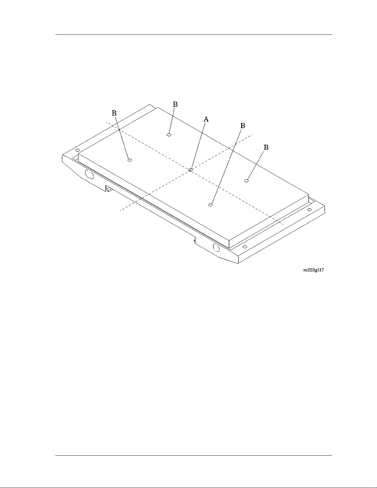
• Measurement points—Measurements are taken at five points in a
plane parallel to and 4" (10 cm) above the mattress surface: One
point (A) is 4" (10 cm) above the center of the mattress, and the
Isolette® Infant Incubator (Model C2000) Service Manual Page 1 - 7
Page 25
Technical Definitions
Chapter 1: Introduction
remaining four points (B) are the centers of four areas formed by
lines that divide both the width and length into two parts (see figure
1-7 on page 1-8).
Figure 1-7. Measurement Points
Page 1 - 8 Isolette® Infant Incubator (Model C2000) Service Manual
Page 26

Introduction
Overview
The Model C2000 Isolette® Infant Incubator provides a therapeutic
environment for the care for low birth-weight neonates. The Model
C2000 Isolette® Infant Incubator provides the following features:
Introduction
Chapter 1: Introduction
1
• Data trending—The unit graphically trends critical data, such as air
temperature, skin temperature, heater power, oxygen, and humidity,
for intervals of 12 to 24 hours, and up to seven days for weight
changes.
• Thermal performance—The unit’s thermal management capabilities
provide a patented dual-air curtain that reduces radiant heat loss
from the infant by warming the surface of the inner hood.
• Bi-directional airflow—Bi-directional airflow minimizes temperature
fluctuations within the incubator when the access doors are opened.
A microprocessor controller quickly and accurately regulates
temperature, humidity, and oxygen levels within the incubator.
• Low operating sound levels—The unit’s low operating sound levels
ensure a developmentally-supportive environment for infants.
• Centralized care for multiple births—The unit allows for co-bedding,
enabling the caregiver to monitor and care for multiple births. The
incubator mattress provides the needed space to care for two
infants and enough room for both to grow comfortably.
• Integrated x-ray cassette tray—Located beneath the mattress, the xray cassette tray slides out smoothly to avoid disturbing the baby.
• Infant access—By using the front and side access, two clinicians
can simultaneously care for an infant while he or she remains in the
incubator, reducing handling and adverse stimulation.
• Servo-controlled oxygen—Oxygen delivery is simplified by selecting
and controlling whole hood oxygen concentrations from 21% to
65%. Calibration can be performed in room air or in 100% oxygen.
The process can be done while the caregiver monitors the infant,
without interfering with the thermal environment.
• Servo-controlled humidity—The front-loading humidity reservoir
requires filling only once every 24 hours. The caregiver can set the
desired relative humidity, minimizing the infant’s evaporative heat
loss.
Isolette® Infant Incubator (Model C2000) Service Manual Page 1 - 9
Page 27

Introduction
Chapter 1: Introduction
Operating Precautions
For additional operating precautions for the Isolette® Infant Incubator
and its accessories, refer to the Isolette® Infant Incubator User Manual.
Features
Oval Access Doors
Dual access doors are provided with a quiet latch.
Mattress Tilt Mechanism
A mattress tilt mechanism is provided, and is continuously variable from
0° to 12° from either end.
Pedestal Stand Assembly
The pedestal stand assembly is available in two models: fixed height
and variable height adjustable.
Oxygen Control System (Optional)
The oxygen control system monitors and controls the oxygen
concentration level within the incubator hood environment.
Humidity System (Optional)
The humidity system monitors and controls the humidity level within the
incubator hood environment.
Weighing Platform (Optional)
A weighing platform located under the mattress measures the weight of
the infant.
Page 1 - 10 Isolette® Infant Incubator (Model C2000) Service Manual
Page 28

Specifications
Physical Description
For the physical specifications of the Model C2000 Isolette® Infant
Incubator, see table 1-1 on page 1-11.
Specifications
Chapter 1: Introduction
1
Table 1-1. Physical Specifications
Feature Dimension
Height from floor (fixed pedestal stand
model)
Height from floor (variable height
adjustable model)
Mattress to floor (fixed pedestal stand
model)
Mattress to floor (variable height
adjustable model)
Depth < 23½" (59.69 cm)
Overall width with tilt knobs < 41" (104 cm)
Weight (fixed pedestal stand model
without options or accessories)
Weight (variable height adjustable
model without options or accessories)
IV pole maximum static load 10.4 lb (4.7 kg)
Monitor shelf maximum static load 25 lb (11 kg)
56" ± ½" (142 cm ± 12.7 mm)
52½" ± ½" to 60" ± ½"
(133.35 cm ± 12.7 mm to
152 cm ± 12.7 mm)
39¾" ± ½" (100.97 cm ±
12.7 mm)
35½" ± ½" to 43½" ± ½"
(90.17 cm ± 12.7 mm to
110.49 cm ± 12.7 mm)
195 lb (88 kg)
200 lb (91 kg)
Mattress tray width 31" (79 cm)
Mattress tray depth 16" (41 cm)
Mattress Trendelenburg/Reverse
Trendelenburg tilt
Environmental temperature operating
range
Storage temperature -4 °F (-20 °C) to 140 °F
Air Mode temperature range 68 °F (20 °C) to 98.6 °F
Isolette® Infant Incubator (Model C2000) Service Manual Page 1 - 11
Continuously variable to 12°
±1°
68 °F (20 °C) to 86 °F
(30 °C)
(60 °C)
(37.0 °C)
Page 29

Specifications
Chapter 1: Introduction
Feature Dimension
Air Mode temperature range in
Temperature Override Mode
98.6 °F (37.0 °C) to 102.2 °F
(39.0 °C)
Skin Mode temperature range 93.2 °F (34.0 °C) to 98.6 °F
(37.0 °C)
Skin Mode temperature range in
Temperature Override Mode
Temperature rise time, typical at 72 F
93.2 °F (34.0 °C) to 100.4 °F
(38.0 °C)
< 35 minutes
(22 C) ambient
Temperature variability < 0.5 C maximum
Temperature overshoot < 0.5 C maximum
Temperature uniformity < 0.8 °C
Correlation of the indicated air temper-
≤ 0.8 °C
ature to the actual incubator temperature after temperature equilibrium is
reached
Page 1 - 12 Isolette® Infant Incubator (Model C2000) Service Manual
Page 30

Electrical Description
For Isolette® Infant Incubator electrical specifications, see table 1-2 on
page 1-13.
Table 1-2. Electrical Specifications
Feature Dimension
Specifications
Chapter 1: Introduction
1
Power requirements of an incubator
with a fixed height pedestal stand
(100V and 120V models)
Power requirements of an incubator
with a variable height adjustable (VHA)
pedestal stand (100V and 120V models)
Power requirements of an incubator
with a fixed height or a VHA pedestal
stand (220V and 240V models)
Convenience outlets (100V and 120V
models)
Convenience outlets (220V and 240V
models)
Chassis current leakage (110V and
120V models)
Chassis current leakage (220V and
240V models)
100V/120V ± 10%, 50/60 Hz,
630 W maximum
100V/120V ± 10%, 50/60 Hz,
1900 W maximum
220V or 240V ± 10%,
50/60 Hz, 2376 W maximum
100V/120V ± 10%, 50/60 Hz,
500 W maximum
220V or 240V, 500 W
maximum
300 μA or less
500 μA or less
Isolette® Infant Incubator (Model C2000) Service Manual Page 1 - 13
Page 31

Specifications
Chapter 1: Introduction
Oxygen Control Description
For Isolette® Infant Incubator oxygen control specifications, see table
1-3 on page 1-14.
Oxygen display range 18% to 100%
Oxygen display resolution 1% oxygen
Table 1-3. Oxygen Control Specifications
Feature Dimension
Oxygen display accuracy (100%
calibration)
Oxygen display accuracy (21% calibration)
Oxygen set resolution 1%
Oxygen setpoint range 21% to 65%
Humidity Description
For Isolette® Infant Incubator humidity specifications, see table 1-4 on
page 1-14.
Feature Dimension
Operating range 5% to 99% relative humidity
Storage range 0% to 99% RH, non-con-
± 3%
± 5%
Table 1-4. Humidity Specifications
(RH), non-condensing
densing
Operating time without refilling > 24 hours maximum at 85%
RH
Humidity control accuracy at 10% to
± 6% RH
80% at 68 F (20 C) to 104 F (60 C)
Maximum humidity level at the incuba-
> 85% RH
tor’s set temperature of 102 F (39 C)
Humidity setpoint range 30% to 95% RH
Page 1 - 14 Isolette® Infant Incubator (Model C2000) Service Manual
Page 32

Scale Description
For Isolette® Infant Incubator scale specifications, see table 1-5 on
page 1-15.
Weight display range 0 kg (0 lb) to 7 kg (15 lb)
Weight display resolution 1 g or 1 oz
Weight display accuracy ± 2 g (0.07 oz) ≤ 2 kg (4.4 lb)
Specifications
Chapter 1: Introduction
1
Table 1-5. Scale Specifications
Feature Dimension
or
± 5 g (0.18 oz) ≥ 5 kg (11 lb)
Weight zeroing limit during infant
weighing
Regulations, Standards, and Codes
The Model C2000 Isolette® Infant Incubator meets the following
specifications:
• IEC 601-1
• IEC 601-2-19
• UL-2601
• With respect to the International Electrotechnical Commission (IEC)
601-1, the incubator is Class 1, Type BF.
• On the variable height adjustable model, the mode of operation is
continuous operation with short-time loading.
> 3.5 kg (7.7 lb)
Isolette® Infant Incubator (Model C2000) Service Manual Page 1 - 15
Page 33

Model Identification and Series Changes
Chapter 1: Introduction
Model Identification and Series Changes
For Isolette® Infant Incubator model identification, see table 1-6 on
page 1-16.
Table 1-6. Model Identification
Model/Series
Number
Description
C2000 Isolette® Infant Incubator
For Isolette® Infant Incubator hood/shell assembly series identification,
see table 1-7 on page 1-16.
Table 1-7. Series Identification for the Hood/Shell Assembly
Model/Series
Number
Description
C2HS-1, C2HS1-400 Isolette® Infant Incubator hood/shell assem-
bly with panel slide latches
C2HS01, C2HS-1,
C2HS-1400
Isolette® Infant Incubator hood/shell assembly with pawl latches
C2HS-02 Isolette® Infant Incubator hood/shell assem-
bly with hood lock
C2HS-03 Isolette® Infant Incubator hood/shell assem-
bly with modification 170
For Isolette® Infant Incubator controller series identification, see table
1-8 on page 1-16.
Table 1-8. Series Identification for the Controller
Model/Series
Number
Description
C2C-2-00 Isolette® Infant Incubator controller
For Isolette® Infant Incubator fixed height pedestal stand assembly
series identification, see table 1-9 on page 1-17.
Page 1 - 16 Isolette® Infant Incubator (Model C2000) Service Manual
Page 34

Model Identification and Series Changes
Chapter 1: Introduction
Table 1-9. Series Identification for the Fixed Height Pedestal Stand
Assembly
1
Model/Series
Number
C2STD1-00 Isolette® Infant Incubator fixed height pedes-
tal stand assembly with upper and lower column extrusion
C2STD1-01 Isolette® Infant Incubator fixed height pedes-
tal stand assembly with upper and lower column weldment
C2STD2-00 Isolette® Infant Incubator fixed height pedes-
tal stand assembly
For Isolette® Infant Incubator variable height adjustable pedestal stand
assembly series identification, see table 1-10 on page 1-17.
Table 1-10. Series Identification for the
Variable Height Adjustable Stand Assembly
Model/Series
Number
C2VHA-1-00 Isolette® Infant Incubator variable height
adjustable pedestal stand assembly
Description
Description
For Isolette® Infant Incubator humidity system series identification, see
table 1-11 on page 1-17.
Table 1-11. Series Identification for the Humidity System
Model/Series
Number
C2RH-1-00 Isolette® Infant Incubator humidity system
C2RH-1-01 Isolette® Infant Incubator humidity system
C2RH-2-00 Isolette® Infant Incubator humidity system
with manifold assembly
Isolette® Infant Incubator (Model C2000) Service Manual Page 1 - 17
Description
Page 35

Safety Tips
Chapter 1: Introduction
Safety Tips
WARNING:
Only facility-authorized personnel should troubleshoot the Model C2000
Isolette® Infant Incubator. Troubleshooting by unauthorized personnel
could result in personal injury or equipment damage.
WARNING:
Do not use the incubator if it fails to function as described. Personal
injury or equipment damage could occur. Refer the unit for servicing by
qualified personnel.
WARNING:
To prevent personal injury or damage to the variable height adjustable
pedestal stand when transporting, employ a person of sufficient
strength to adequately control the incubator.
WARNING:
A dirty air intake microfilter may affect oxygen concentrations and/or
cause carbon dioxide build-up. Check the filter routinely, and change it
at least every 3 months or when it is visibly dirty. Failure to do so could
result in infant injury.
WARNING:
Two people are required to lift the hood assembly. Failure to use at
least two people could result in personal injury or equipment damage.
WARNING:
Allow 45 minutes for the heater assembly to cool. Failure to do so could
result in personal injury.
WARNING:
Follow the product manufacturer’s instructions. Failure to do so could
result in personal injury or equipment damage.
Page 1 - 18 Isolette® Infant Incubator (Model C2000) Service Manual
Page 36

Safety Tips
Chapter 1: Introduction
WARNING:
Make sure that the oxygen supply to the incubator is turned off and that
the incubator is disconnected from the oxygen supply when performing
cleaning procedures. A fire and explosion hazard exists when cleaning
in an oxygen-enriched environment.
WARNING:
Failure to clean the heater radiator and fan impeller could result in
sufficient lint build-up to reduce airflow, which will affect temperature
control and cause high oxygen concentrations. Infant injury could occur.
WARNING:
Only facility-authorized personnel should perform preventive
maintenance on the Model C2000 Isolette® Infant Incubator.
Preventive maintenance performed by unauthorized personnel could
result in personal injury or equipment damage.
1
WARNING:
Make sure that the oxygen supply to the incubator is turned off and that
the incubator is disconnected from the oxygen supply when performing
maintenance procedures. A fire and explosion hazard exists when
performing maintenance procedures in an oxygen-enriched
environment.
WARNING:
The hood/shell assembly must attach to the pedestal/stand using the
screws provided. Failure to do so could result in the hood/shell
assembly separating from the pedestal stand when sufficiently tilted,
particularly with the hood open. Personal injury or equipment damage
could occur.
WARNING:
To keep the incubator from sliding when parked on an incline, the
pedestal stand’s front locking casters must be facing down the incline
and locked.
Isolette® Infant Incubator (Model C2000) Service Manual Page 1 - 19
Page 37

Safety Tips
Chapter 1: Introduction
WARNING:
For the 21% oxygen calibration, the unit must be equipped with a
standard sensor module lock. Failure to use a standard sensor module
could result in incorrect calibration. Infant injury could occur.
WARNING:
For the 100% oxygen calibration procedure, the incubator hood must
be equipped with the 100% calibration fixture. Failure to use the 100%
calibration fixture could result in incorrect calibration. Infant injury could
occur.
WARNING:
Oxygen flow rates cannot be used as an accurate indication of oxygen
concentration in an incubator. Continuously monitor the oxygen
concentrations with a calibrated oxygen analyzer. Failure to do so could
result in personal injury or equipment damage.
WARNING:
Ensure all sensor leads are properly routed. Use cable management
clips to avoid entanglement and possible infant injury.
SHOCK HAZARD:
Ensure that the building power source is compatible with the electrical
specifications shown on the right side of the incubator and the variable
height adjustable pedestal stand. For proper grounding reliability,
connect the power cord only to a properly marked, three-wire, hospitalgrade or hospital-use receptacle. Do not use extension cords.
SHOCK HAZARD:
Unplug the unit from its power source. Failure to do so could result in
personal injury or equipment damage.
SHOCK HAZARD:
Unplug the power cord from the controller assembly. Failure to do so
could result in personal injury or equipment damage.
Page 1 - 20 Isolette® Infant Incubator (Model C2000) Service Manual
Page 38

Safety Tips
Chapter 1: Introduction
SHOCK HAZARD:
Do not expose the unit to excessive moisture. Personal injury or
equipment damage could occur.
CAUTION:
When using the variable height adjustable pedestal stand, always lower
the incubator to its lowest position prior to transport for optimum
stability. Failure to do so could result in personal injury or equipment
damage.
CAUTION:
Replace both oxygen sensor cells at the same time. Failure to do so
could result in equipment damage.
CAUTION:
When reconnecting the rear panel connectors, connect the sensor
module-to-connector cable assembly to the sensor module connector
only. Do not connect the sensor module cable to the RS-232
connector. Equipment damage could occur.
1
CAUTION:
Always replace Nylok®1 screws; do not reuse them. Equipment
damage could occur.
CAUTION:
Use caution when lowering the shell assembly in place on the shell
bottom. Ensure that no cables are pinched and that the extrusion
bumper fits properly. Failure to do so could result in equipment
damage.
CAUTION:
Do not use harsh cleansers, such as scouring pads or heavy-duty
grease removers or solvents, such as acetone. Equipment damage
could occur.
1. Nylok® is a registered trademark of Nylok Fastener Corporation.
Isolette® Infant Incubator (Model C2000) Service Manual Page 1 - 21
Page 39

Safety Tips
Chapter 1: Introduction
CAUTION:
Some chemical cleaning agents may be conductive and/or leave a
residue that may enable a build-up of conductive dust or dirt. Do not
permit cleaning agents to contact electrical components. Do not spray
cleaning solutions onto any of these surfaces. Equipment damage
could occur.
CAUTION:
When cleaning the interior of the incubator shell, prevent liquids from
entering the motor shaft opening. Equipment damage could occur.
CAUTION:
Do not use alcohol for cleaning. Alcohol can cause crazing of the clear
acrylic hood.
CAUTION:
Do not expose the hood assembly to direct radiation from germicidal
lamps. Ultraviolet radiation from these sources can cause cracking of
gaskets, fading of paint, and crazing of the clear acrylic hood.
CAUTION:
To prevent component damage, ensure that your hands are clean, and
only handle the P.C. board by its edges.
CAUTION:
When handling electronic components, wear an antistatic strap. Failure
to do so could result in component damage.
CAUTION:
For shipping and storage, place the removed P.C. board in an antistatic
protective bag. Equipment damage can occur.
CAUTION:
Do not use silicone-based lubricants. Equipment damage could occur.
Page 1 - 22 Isolette® Infant Incubator (Model C2000) Service Manual
Page 40

Safety Tips
Chapter 1: Introduction
CAUTION:
When removing the equipment from the cartons, take care not to
scratch or otherwise damage unprotected surfaces.
CAUTION:
Before lifting the incubator hood for cleaning, ensure that all mounted
accessories have been removed to prevent possible interference with
the raised hood.
CAUTION:
To avoid equipment damage, use only distilled or sterile distilled water.
Sterile water alone is not an acceptable substitute for distilled water.
CAUTION:
Use only the programming cable assembly (P/N 83 930 70) to install
the software update. Using a standard RS-232 cable assembly could
result in equipment damage.
1
CAUTION:
To prevent damage to the collar that secures the evaporator assembly
to the shell assembly, be careful not to twist the evaporator assembly
around the horizontal axis when installing its tubing.
Isolette® Infant Incubator (Model C2000) Service Manual Page 1 - 23
Page 41

Warning and Caution Labels
Chapter 1: Introduction
Warning and Caution Labels
Figure 1-8. Warning and Caution Labels
Page 1 - 24 Isolette® Infant Incubator (Model C2000) Service Manual
Page 42

Chapter 2
Troubleshooting Procedures
Chapter Contents
Getting Started . . . . . . . . . . . . . . . . . . . . . . . . . . . . . . . . . . . . . . . . . . . . . . 2 - 5
Initial Actions . . . . . . . . . . . . . . . . . . . . . . . . . . . . . . . . . . . . . . . . . . . . . . . 2 - 5
Function Checks. . . . . . . . . . . . . . . . . . . . . . . . . . . . . . . . . . . . . . . . . . . . . 2 - 6
Final Actions. . . . . . . . . . . . . . . . . . . . . . . . . . . . . . . . . . . . . . . . . . . . . . . 2 - 24
Alarms . . . . . . . . . . . . . . . . . . . . . . . . . . . . . . . . . . . . . . . . . . . . . . . . . . . 2 - 25
High and Low Air and Skin Temperature Alarms . . . . . . . . . . . . . . . . 2 - 25
Alarm and System Prompt Messages. . . . . . . . . . . . . . . . . . . . . . . . . 2 - 26
System Failure Messages . . . . . . . . . . . . . . . . . . . . . . . . . . . . . . . . . . . . 2 - 33
2
Diagnostic Menus . . . . . . . . . . . . . . . . . . . . . . . . . . . . . . . . . . . . . . . . . . . 2 - 35
Entering the System Configuration Menu . . . . . . . . . . . . . . . . . . . . . . 2 - 35
Entering the Diagnostic Information Menu . . . . . . . . . . . . . . . . . . . . . 2 - 37
System Test Menu . . . . . . . . . . . . . . . . . . . . . . . . . . . . . . . . . . . . . . . 2 - 40
System Test (1 of 3) Menu . . . . . . . . . . . . . . . . . . . . . . . . . . . . . . 2 - 40
System Test (2 of 3) Menu . . . . . . . . . . . . . . . . . . . . . . . . . . . . . . 2 - 42
System Test (3 of 3) Menu . . . . . . . . . . . . . . . . . . . . . . . . . . . . . . 2 - 43
Key Check Display . . . . . . . . . . . . . . . . . . . . . . . . . . . . . . . . . . . . . . . 2 - 45
Data Summary Menu . . . . . . . . . . . . . . . . . . . . . . . . . . . . . . . . . . . . . 2 - 46
Data Summary (1 of 2) Menu . . . . . . . . . . . . . . . . . . . . . . . . . . . . 2 - 46
Data Summary (2 of 2) Menu . . . . . . . . . . . . . . . . . . . . . . . . . . . . 2 - 48
There Is No Power, and Power Failure Alarm Does Not Activate . . . . . . 2 - 51
Variable Height Adjustable (VHA) Pedestal/Stand Does Not Move Up or
Down . . . . . . . . . . . . . . . . . . . . . . . . . . . . . . . . . . . . . . . . . . . . . . . . . . . . 2 - 52
Skin Set Temperature Cannot Be Achieved or Maintained . . . . . . . . . . . 2 - 54
Isolette® Infant Incubator (Model C2000) Service Manual Page 2 - 1
Page 43

Chapter 2: Troubleshooting Procedures
Oxygen Concentration is Low . . . . . . . . . . . . . . . . . . . . . . . . . . . . . . . . . .2 - 56
Oxygen Concentration is High . . . . . . . . . . . . . . . . . . . . . . . . . . . . . . . . .2 - 58
Hood Does Not Tilt or Close Properly . . . . . . . . . . . . . . . . . . . . . . . . . . . .2 - 60
Controller Failure #1—EEPROM Circuitry Failure . . . . . . . . . . . . . . . . . . 2 - 63
Controller Failure #2—Ambient Air Probe Failure. . . . . . . . . . . . . . . . . . .2 - 64
Controller Failure #4—Controller Cooling Fan Failure . . . . . . . . . . . . . . .2 - 65
Controller Failure #5—Display Test Failure . . . . . . . . . . . . . . . . . . . . . . .2 - 66
Controller Failure #7—Power Supply Voltage Failure. . . . . . . . . . . . . . . . 2 - 67
Controller Failure #8—RAM Test Failure . . . . . . . . . . . . . . . . . . . . . . . . .2 - 68
Controller Failure #9—Real-Time Clock Failure . . . . . . . . . . . . . . . . . . . .2 - 69
Controller Failure #10—Watchdog Timer Failure . . . . . . . . . . . . . . . . . . .2 - 70
Controller Failure #11—Relay Test Failure. . . . . . . . . . . . . . . . . . . . . . . . 2 - 71
Controller Failure #13—Heater Circuit Failure Detected. . . . . . . . . . . . . . 2 - 72
Controller Failure #14—Low Heater Current Detected . . . . . . . . . . . . . . . 2 - 73
Heater Thermocouple Does Not Work Properly . . . . . . . . . . . . . . . . . . . . 2 - 74
Humidity Heater Draws Too Much Current . . . . . . . . . . . . . . . . . . . . . . . .2 - 76
Motor Fails . . . . . . . . . . . . . . . . . . . . . . . . . . . . . . . . . . . . . . . . . . . . . . . .2 - 77
Communication Between the Sensor Module and the Controller Fails. . . 2 - 78
Sensor Module Is Out of Position . . . . . . . . . . . . . . . . . . . . . . . . . . . . . . .2 - 80
A Stuck Key Is Detected . . . . . . . . . . . . . . . . . . . . . . . . . . . . . . . . . . . . . .2 - 81
Unit Fails the Non-Volatile Memory (NVM) Integrity Test . . . . . . . . . . . . .2 - 82
Access Panel Assembly Does Not Latch Properly . . . . . . . . . . . . . . . . . .2 - 83
Iris Entry Port Does Not Open or Close Properly . . . . . . . . . . . . . . . . . . .2 - 85
Access Door Does Not Operate or Latch Properly . . . . . . . . . . . . . . . . . .2 - 86
Heat Shield Does Not Latch Properly . . . . . . . . . . . . . . . . . . . . . . . . . . . .2 - 88
Mattress Tray Does Not Tilt Properly . . . . . . . . . . . . . . . . . . . . . . . . . . . .2 - 90
Mattress Tray Is Damaged . . . . . . . . . . . . . . . . . . . . . . . . . . . . . . . . . . . .2 - 92
Air Intake Is Not Working Properly . . . . . . . . . . . . . . . . . . . . . . . . . . . . . .2 - 94
X-ray Tray Does Not Operate Properly . . . . . . . . . . . . . . . . . . . . . . . . . . .2 - 96
Sensor Module Lock Does Not Secure the Sensor Module
(Units Equipped With the Sensor Module Lock Only) . . . . . . . . . . . . . . . .2 - 98
Page 2 - 2 Isolette® Infant Incubator (Model C2000) Service Manual
Page 44

Chapter 2: Troubleshooting Procedures
Incubator Takes Longer Than One Hour to Warm Up to the Air Set
Temperature. . . . . . . . . . . . . . . . . . . . . . . . . . . . . . . . . . . . . . . . . . . . . . . 2 - 99
Air Set Temperature Cannot Be Maintained. . . . . . . . . . . . . . . . . . . . . . 2 - 101
Low Air Temperature Alarm or High Air Temperature Alarm Does Not Sound
When Air Temperature Drops or Rises Out of Specification . . . . . . . . . 2 - 102
Low Skin Temperature Alarm or High Skin Temperature Alarm Does Not Sound
When Skin Temperature Drops or Rises Out of Specification . . . . . . . . 2 - 103
When Skin Probes are Disconnected, Connect Skin 1 Probe Alarm
Does Not Sound . . . . . . . . . . . . . . . . . . . . . . . . . . . . . . . . . . . . . . . . . . . 2 - 104
Incubator’s Air Temperature Exceeds Air Set Temperature by 1.5 C or Greater, or
Infant’s Skin Temperature Exceeds Skin Set Temperature by 1.0 C or
Greater . . . . . . . . . . . . . . . . . . . . . . . . . . . . . . . . . . . . . . . . . . . . . . . . . . 2 - 105
Humidity System Is Not Working Properly . . . . . . . . . . . . . . . . . . . . . . . 2 - 106
Power Failure Alarm Sounds . . . . . . . . . . . . . . . . . . . . . . . . . . . . . . . . . 2 - 108
Skin 1 Probe Does Not Work Properly . . . . . . . . . . . . . . . . . . . . . . . . . . 2 - 109
Oxygen System Is Not Working Properly
(Units Equipped With an Oxygen System Only). . . . . . . . . . . . . . . . . . . 2 - 112
Poor Air Circulation Exists Within the Incubator. . . . . . . . . . . . . . . . . . . 2 - 113
Sensor Module Assembly Fails . . . . . . . . . . . . . . . . . . . . . . . . . . . . . . . 2 - 114
Remove Skin 2 Probe Alarm Sounds . . . . . . . . . . . . . . . . . . . . . . . . . . . 2 - 115
Scale Is Not Working Properly . . . . . . . . . . . . . . . . . . . . . . . . . . . . . . . . 2 - 116
Oxygen System’s Cal Fail System Prompt Message Appears. . . . . . . . 2 - 119
2
Isolette® Infant Incubator (Model C2000) Service Manual Page 2 - 3
Page 45

Chapter 2: Troubleshooting Procedures
NOTES:
Page 2 - 4 Isolette® Infant Incubator (Model C2000) Service Manual
Page 46

Getting Started
WARNING:
Only facility-authorized personnel should troubleshoot the Model C2000
Isolette® Infant Incubator. Troubleshooting by unauthorized personnel
could result in personal injury or equipment damage.
Begin each procedure in this chapter with step 1. Follow the sequence
outlined (each step assumes the previous step has been completed). In
each step, the normal operation of the product can be confirmed by
answering Yes or No to the statement. Your response will lead to
another step in the procedure, a repair analysis procedure (RAP), or a
component replacement. If more than one component is listed, replace
them in the given order.
To begin gathering information about the problem, start with Initial
Actions.
Getting Started
Chapter 2: Troubleshooting Procedures
2
To isolate or identify a problem and to verify the repair after completing
each corrective action (replacing or adjusting a part, seating a
connector, etc.), perform the Function Checks.
To verify the repair, perform the Final Actions after the Function
Checks.
If troubleshooting procedures do not isolate the problem, call Technical
Support at (800) 437-2437 for assistance.
Initial Actions
To gather information from operators concerning problems with the
Isolette® Infant Incubator, use Initial Actions. Note symptoms or other
information concerning the problem that the operator describes. This
information helps identify the probable cause.
1. Someone who can explain the problem is available.
Yes No
↓→Go to “Function Checks” on page 2-6.
2. Ask that person to demonstrate or explain the problem. The problem
can be duplicated.
Isolette® Infant Incubator (Model C2000) Service Manual Page 2 - 5
Page 47

Function Checks
Chapter 2: Troubleshooting Procedures
Yes No
↓→Go to “Function Checks” on page 2-6.
3. The problem is a result of improper operator action.
Yes No
↓→Go to “Function Checks” on page 2-6.
4. Instruct the operator to refer to the procedures in the Isolette® Infant
Incubator User Manual (usr032). To ensure proper operation of the
Isolette® Infant Incubator, perform the “Function Checks” on page
2-6.
Function Checks
NOTE:
Perform Function Checks before the incubator is first placed into
service and after any disassembly for cleaning or maintenance.
Page 2 - 6 Isolette® Infant Incubator (Model C2000) Service Manual
Page 48

Function Checks
Chapter 2: Troubleshooting Procedures
WARNING:
Do not use the incubator if it fails to function as described. Personal
injury or equipment damage could occur. Refer the unit for servicing by
qualified personnel.
SHOCK HAZARD:
Ensure that the building power source is compatible with the electrical
specifications shown on the right side of the incubator and the variable
height adjustable pedestal stand. For proper grounding reliability,
connect the power cord only to a properly marked, three-wire, hospitalgrade or hospital-use receptacle. Do not use extension cords.
WARNING:
To prevent injury or damage to the variable height adjustable pedestal
stand when transporting, employ a person of sufficient strength to
adequately control the incubator.
CAUTION:
When using the variable height adjustable pedestal stand, always lower
the incubator to its lowest position prior to transport for optimum
stability.
1. Initial Actions have been performed.
Yes No
↓→Go to “Initial Actions” on page 2-5.
2
2. Connect the AC power cord to the pedestal stand, and apply power:
a. Plug the power cord into an appropriate power source.
b. Press the Power switch on the pedestal stand.
c. Press the Power switch on the incubator’s controller.
NOTE:
When turned on, the unit performs a self-test indicated by the PowerUp Tests screen. After the self-test, Display #1 appears.
All indicator lamps light, and the audible alarm pulses.
Yes No
↓→The unit fails the self-test, the alarm sounds, and one or
more system failure messages appear in the Trend
Isolette® Infant Incubator (Model C2000) Service Manual Page 2 - 7
Page 49

Function Checks
Chapter 2: Troubleshooting Procedures
display on Display #1. Go to “System Failure Messages”
on page 2-33.
3. The Trend display is free from any alarm or system prompt
messages.
Yes No
↓→Go to “Alarms” on page 2-25.
4. Perform the following:
a. Allow the unit to operate for at least 3 minutes.
b. Check the Power Failure alarm by unplugging the power cord
from its power source.
The Power Failure alarm sounds, and the Power Fail light-emitting
diode (LED) on the controller actuates.
Yes No
↓→Go to RAP 2.1 on page 2-51.
5. Perform the following:
a. Plug the power cord into an appropriate power source. Ensure
that the power cord is fully plugged into the wall, the pedestal
stand, and the incubator receptacles.
b. S et the air set temperature to 95 F (35 C). Allow the unit to
operate while checking the hood/shell.
The unit has a variable height adjustable (VHA) pedestal stand (A)
(see figure 2-1 on page 2-9).
Yes No
↓→Go to step 8.
Page 2 - 8 Isolette® Infant Incubator (Model C2000) Service Manual
Page 50

Chapter 2: Troubleshooting Procedures
Figure 2-1. Isolette® Infant Incubator
Function Checks
2
Isolette® Infant Incubator (Model C2000) Service Manual Page 2 - 9
Page 51

Function Checks
Chapter 2: Troubleshooting Procedures
6. Perform the following to check the operation of the VHA
pedestal/stand (A):
a. Using your foot, press the Up arrow on the front Up/Down switch
(C) to raise the VHA pedestal/stand (A) to the maximum height.
b. Press and hold the Down arrow on the Up/Down switch (C) to
lower the VHA pedestal/stand (A) to the minimum height.
c. Repeat using the rear Up/Down switch (C).
The VHA pedestal/stand (A) operates smoothly and adjusts to the
desired height.
Yes No
↓→Go to RAP 2.2 on page 2-52.
7. The unit is equipped with a non-locking hood assembly (D).
Yes No
↓→Go to step 9.
8. Perform the following to check the operation of the non-locking hood
assembly (D) (see figure 2-1 on page 2-9):
a. Disconnect the weighing scale cable (E) from the sensor module
(F).
b. Slowly tilt the hood assembly (D) back until it comes to rest.
c. Close the hood assembly (D).
d. Connect the weighing scale cable (E) to the sensor module (F).
The hood assembly (D) opens and closes correctly.
Yes No
↓→Go to RAP 2.6 on page 2-60.
9. The hood assembly (D) is equipped with a pivot/hood lock assembly
bracket (G).
Yes No
↓→Go to step 11.
10.On the hood assembly (D) equipped with a pivot/hood lock
assembly bracket (G), perform the following:
a. Disconnect the weighing scale cable (E) from the sensor module
(F).
b. Slowly tilt the hood assembly (D) back until it locks in place.
Page 2 - 10 Isolette® Infant Incubator (Model C2000) Service Manual
Page 52

Function Checks
Chapter 2: Troubleshooting Procedures
c. Release the hood assembly (D) by pulling and holding the knob
(H) located on the right rear pivot/hood lock assembly bracket
(G) while closing the hood assembly (D).
d. Connect the weighing scale cable (E) to the sensor module (F).
The pivot/hood lock assembly bracket (G) operates properly.
Yes No
↓→Go to RAP 2.6 on page 2-60.
11. Perform the following to check the operation of the access panel (I)
(see figure 2-2 on page 2-11).
Figure 2-2. Access Panels
2
a. On a unit with a Series 00 hood assembly (D), slide the blue
slide access panel latches (J), and open the access panel (I).
or
On a unit with a hood assembly (D) later than Series 00, rotate
the access panel pawl latch knobs (K), and open the access
panel (I).
b. Pivot the access panel (I) to the full-open position so it hangs
straight down.
c. Check the rear access panel (I), if so equipped.
Isolette® Infant Incubator (Model C2000) Service Manual Page 2 - 11
Page 53

Function Checks
Chapter 2: Troubleshooting Procedures
d. Close each access panel (I), and secure them using the blue
slide access panel latches (J) or the access panel pawl latch
knobs (K).
The blue slide access panel latches (J) or the access panel pawl
latch knobs (K) are properly secured to avoid accidental opening of
the access panel(s) (I).
Yes No
↓→Go to RAP 2.25 on page 2-83.
12.The hood assembly (D) is equipped with an iris entry port (L) (see
figure 2-3 on page 2-12).
Yes No
↓→Go to step 14.
Figure 2-3. Iris Entry Port and Access Doors
13.Check the iris entry port (L) by rotating its outer ring (N). The iris
entry port (L) opens and closes as rotation is continued through
360 .
Yes No
↓→Go to RAP 2.26 on page 2-85.
14.The hood assembly (D) is equipped with an access door (O).
Page 2 - 12 Isolette® Infant Incubator (Model C2000) Service Manual
Page 54

Function Checks
Chapter 2: Troubleshooting Procedures
Yes No
↓→Go to step 17.
15.Press the door release (Q) of each access door (O). Each access
door (O) swings open.
Yes No
↓→Go to RAP 2.27 on page 2-86.
16.Close the access doors (O), and check for proper latching and
quietness. The gaskets (R) of each access door (O) are placed
properly on the inner and outer walls.
Yes No
↓→Go to RAP 2.27 on page 2-86.
17.Perform the following:
a. On a unit with a Series 00 hood assembly (D), slide the blue
slide access panel latches (J), and open the access panel (I)
(see figure 2-2 on page 2-11).
or
On a unit with a hood assembly (D) later than Series 00, rotate
the access panel pawl latch knobs (K), and open the access
panel (I).
2
b. Inspect the heat shield latches (S) and the heat shield (T) (see
figure 2-4 on page 2-14).
Isolette® Infant Incubator (Model C2000) Service Manual Page 2 - 13
Page 55

Function Checks
Chapter 2: Troubleshooting Procedures
Figure 2-4. Heat Shield
The heat shield latches (S) properly secure the heat shield (T).
Yes No
↓→Go to RAP 2.28 on page 2-88.
18.Perform the following to check the operation of the mattress tilt
mechanisms:
a. Check the mattress elevators by rotating the right-hand mattress
tilt mechanism knob (U) counterclockwise until it stops and the
right end of the mattress tray (V) is at a 12 angle (see figure 25 on page 2-15).
Page 2 - 14 Isolette® Infant Incubator (Model C2000) Service Manual
Page 56

Chapter 2: Troubleshooting Procedures
Figure 2-5. Mattress Tray Assembly
Function Checks
2
b. Rotate the right-hand mattress tilt mechanism knob (U)
clockwise until it stops and the mattress tray (V) is level.
c. Rotate the left-hand mattress tilt mechanism knob (U) clockwise
and the left end of the mattress tray (V) is at a 12 angle.
d. Rotate the left-hand mattress tilt mechanism knob (U)
counterclockwise and the mattress tray (V) is level.
The mattress tray (V) correctly tilts with the rotation of the mattress
tilt mechanism knobs (U).
Yes No
↓→Go to RAP 2.29 on page 2-90.
19.Perform the following to check the mattress tray (V) operation:
a. Slide out the mattress tray (V) to the fully-extended position.
b. Gradually load a calibrated weight of 22 lb (10 kg) near the front-
center of the extended mattress tray (V).
The mattress tray (V) is a firm platform for an infant.
Yes No
↓→Go to RAP 2.30 on page 2-92.
Isolette® Infant Incubator (Model C2000) Service Manual Page 2 - 15
Page 57

Function Checks
Chapter 2: Troubleshooting Procedures
20.Perform the following to check the operation of the air intake
microfilter (W) (see figure 2-6 on page 2-16):
Figure 2-6. Air Intake Microfilter and Oxygen Input Connector
a. Return the mattress tray (V) to its original position (see figure 2-5
on page 2-15).
b. Close the access panel (I), and secure it using its blue slide
access panel latches (J) or its access panel pawl latch knobs (K)
(see figure 2-2 on page 2-11).
WARNING:
A dirty air intake microfilter may affect oxygen concentrations and/or
cause carbon dioxide build-up. Check the filter routinely, and change it
at least every 3 months or when it is visibly dirty. Failure to do so could
result in infant injury.
c. Loosen the two thumbscrews (X) on the air intake filter cover (Y)
(see figure 2-6 on page 2-16).
d. Remove the air intake filter cover (Y) from the unit.
e. Inspect the air intake microfilter (W).
Page 2 - 16 Isolette® Infant Incubator (Model C2000) Service Manual
Page 58

Function Checks
Chapter 2: Troubleshooting Procedures
The air intake microfilter (W) has no visible dirt.
Yes No
↓→Go to RAP 2.31 on page 2-94.
21.Perform the following to check the operation of the air/oxygen
system.
a. Introduce 9 lpm of oxygen into the oxygen input connector (Z).
b. Using a calibrated oxygen analyzer, monitor the oxygen levels
within the hood assembly (D) (see figure 2-3 on page 2-12).
The oxygen levels meet the specification of 50% to 70% as
indicated on the rear panel of the incubator.
Yes No
↓→Go to step 23.
22.Go to step 25.
23.The oxygen concentration level is lower than 50% to 70%.
Yes No
↓→The oxygen concentration level is higher than 50% to
70%.
Go to RAP 2.5 on page 2-58.
24.Go to RAP 2.4 on page 2-56.
25.Perform the following to check the operation of the x-ray tray (AA)
(see figure 2-7 on page 2-18):
2
Isolette® Infant Incubator (Model C2000) Service Manual Page 2 - 17
Page 59

Function Checks
Chapter 2: Troubleshooting Procedures
Figure 2-7. X-ray Tray
a. On a unit with a Series 00 hood assembly (D), slide the blue
slide access panel latches (J), and open the access panel (I)
(see figure 2-2 on page 2-11).
or
On a unit with a hood assembly (D) other than Series 00, rotate
the access panel pawl latch knobs (K), and open the access
panel (I).
b. Withdraw the x-ray tray (AA) (see figure 2-7 on page 2-18).
c. Return the x-ray tray (AA) to its original position.
d. Close the access panel (I), and secure it using its blue slide
access panel latches (J) or its access panel pawl latch knobs (K)
(see figure 2-2 on page 2-11).
The x-ray tray (AA) operates correctly (see figure 2-7 on page 2-18).
Yes No
↓→Go to RAP 2.32 on page 2-96.
26.The hood assembly (D) is equipped with a sensor module lock (AB)
(see figure 2-8 on page 2-19).
Page 2 - 18 Isolette® Infant Incubator (Model C2000) Service Manual
Page 60

Chapter 2: Troubleshooting Procedures
Figure 2-8. Sensor Module and Sensor Module Lock
Function Checks
2
Yes No
↓→Go to step 28.
27.Perform the following to check the operation of the sensor module
lock (AB).
a. Pull the sensor module lock (AB) down.
b. Slide the sensor module (F) out until it stops.
c. Pull the slide assemblies (AC) on the sides of the sensor module
(F) to release its stop, and slide the sensor module (F)
completely out of the hood assembly (D).
d. Return the sensor module (F) to the hood assembly (D). Ensure
that the sensor module (F) is fully engaged in the sensor module
lock (AB).
e. Push the sensor module lock (AB) up.
When the sensor module lock (AB) is raised, the sensor module (F)
is locked securely in place.
Yes No
↓→Go to RAP 2.33 on page 2-98.
Isolette® Infant Incubator (Model C2000) Service Manual Page 2 - 19
Page 61

Function Checks
Chapter 2: Troubleshooting Procedures
28.Perform the following to check the operation of Air Mode:
a. Close all access openings.
b. Allow the incubator to warm up to the air set temperature of
95 F (35 C).
The incubator takes less than one hour to warm up to the air set
temperature of 95 F (35 C).
Yes No
↓→Go to RAP 2.34 on page 2-99.
29.When the Air Temperature display stabilizes, the digital display
remains within 0.5 C of the set temperature for 15 minutes.
Yes No
↓→Go to RAP 2.35 on page 2-101.
30.Perform the following to check the Low Air Temperature alarm:
a. On a unit with a Series 00 hood assembly (D), slide the blue
slide access panel latches (J), and open the access panel (I)
(see figure 2-2 on page 2-11).
or
On a unit with a hood assembly (D) later than Series 00, rotate
the access panel pawl latch knobs (K), and open the access
panel (I).
b. Pivot the access panel (I) to the full-open position so it hangs
straight down.
c. Allow the unit to operate.
In less than 5 minutes, the Alarm indicators illuminate, the Low Air
Temperature message appears on the Trend display, and an alarm
sounds.
Yes No
↓→Go to RAP 2.36 on page 2-102.
31.Perform the following to check the Low Skin Temperature alarm:
a. Close the access panel (I), and secure it using its blue slide
access panel latches (J) or its access panel pawl latch knobs
(K).
b. Connect the skin probe to skin connector #1 on the sensor
module (F) (see figure 2-8 on page 2-19).
c. Place the skin probe 4" (10 cm) above the center of the mattress.
d. Select Skin Mode.
Page 2 - 20 Isolette® Infant Incubator (Model C2000) Service Manual
Page 62

Function Checks
Chapter 2: Troubleshooting Procedures
e. S et the skin set temperature to 95 F (35 C).
f. When the temperature stabilizes, position the skin probe outside
of the incubator.
g. Allow the unit to operate.
In less than 5 minutes, the Alarm indicators illuminate, the Low
Skin Temperature message appears in place of the Trend display,
and the alarm sounds.
Yes No
↓→Go to RAP 2.37 on page 2-103.
NOTE:
The sensor module is equipped to accept two skin probes. However,
when the second skin probe is connected to the sensor module in Skin
Mode, an alarm sounds, and the message Remove Skin 2 Probe
appears. To connect the second skin probe, first select Air Mode, the
controller then displays two temperatures.
2
32.Perform the following to check the Skin Probe Disconnect alarm:
a. Remove the skin probe from the 2 skin connector on the sensor
module (F) (see figure 2-8 on page 2-19).
b. Select Skin Mode.
c. Disconnect the skin probe from the 1 skin connector on the
sensor module (F).
The alarm sounds, the Skin Temperature display goes blank (--.-),
and the message Skin Probe Disconnect appears.
Yes No
↓→Go to RAP 2.38 on page 2-104.
33.Perform the following to check the maximum air temperature.
a. Press the Silence/Reset key to silence the Skin Probe
Disconnect alarm for 5 minutes.
b. Connect a skin probe to the 1 skin connector on the sensor
module (F) to return the unit to normal operation.
c. If necessary, select Skin Mode.
d. Select a skin temperature setpoint of greater than 99 F (37 C).
e. Place the skin probe outside of the incubator.
f. Allow the incubator to heat.
Isolette® Infant Incubator (Model C2000) Service Manual Page 2 - 21
Page 63

Function Checks
Chapter 2: Troubleshooting Procedures
g. When the Skin Temperature alarm sounds, press the
Silence/Reset key.
The incubator’s temperature stays below 10 2.0 F (38. 9C), as
indicated by the Air Temperature display.
Yes No
↓→Go to RAP 2.39 on page 2-105.
34.The incubator is equipped with a scale assembly.
Yes No
↓→Go to step 38.
35.Perform the following to check the operation of the scale assembly:
a. Ensure that the mattress tray is level and not in Trendelenburg
or Reverse Trendelenburg.
b. If you desire a pounds/ounces display, refer to “Installation and
Set-up” on page 6-13.
c. Remove any objects from the mattress.
d. Select Display 2, and press the Weigh softkey.
e. Press the Zero softkey twice in succession.
The Weight display reads 0, and the Weight Sample bar begins to
fill.
Yes No
↓→Go to RAP 2.47 on page 2-116.
36.Place a weight of known value less than 15 lb (7 kg) on the
mattress. The correct weight appears, and when the Weight
Sample bar is filled, a beep sounds and the weight is locked into the
Weight display.
Yes No
↓→Go to RAP 2.47 on page 2-116.
37.Perform the following:
a. Press the Home key to return to Display 2.
b. Press the Weigh softkey.
The display again displays the value of the weight on the mattress.
Yes No
↓→Go to RAP 2.47 on page 2-116.
Page 2 - 22 Isolette® Infant Incubator (Model C2000) Service Manual
Page 64

Function Checks
Chapter 2: Troubleshooting Procedures
38.If necessary, remove the weight from the mattress, and press the
Home softkey. The incubator is equipped with an oxygen system
accessory.
Yes No
↓→Go to step 43.
39.Perform the following to check the operation of the oxygen system
accessory:
a. Place a calibrated oxygen analyzer inside the hood assembly at
4"
(10 cm) above the center mattress.
b. At Display 1, press the Oxygen softkey.
c. Turn on Oxygen control.
d. Set the oxygen setpoint to 45%.
Within 5 minutes, the oxygen analyzer and the Oxygen display both
read 45% ± 5%.
Yes No
↓→Go to step 41.
40.Go to step 43.
41.The oxygen concentration level is lower than 50% to 70%.
Yes No
↓→The oxygen concentration level is higher than 50% to
70%.
Go to RAP 2.5 on page 2-58.
2
42.Go to RAP 2.4 on page 2-56.
43.The incubator is equipped with a humidity system accessory.
Yes No
↓→Go to “Final Actions” on page 2-24.
44.Perform the following to check the operation of the humidity system
accessory:
CAUTION:
To avoid equipment damage, use only distilled or sterile distilled water.
Sterile water alone is not an acceptable substitute for distilled water.
a. Fill the humidity reservoir with distilled water only.
Isolette® Infant Incubator (Model C2000) Service Manual Page 2 - 23
Page 65

Final Actions
Chapter 2: Troubleshooting Procedures
b. Place the probe of a calibrated hygrometer inside the hood
assembly at 4" (10 cm) above the center mattress.
c. If necessary, select Air Mode.
d. Pre-warm the incubator to 95 F (35 C).
e. At Display 1, press the Humidity softkey to turn on the humidity.
f. Set the humidity setpoint to 50%.
NOTE:
The humidity system sensor has a tolerance of ± 6% relative humidity
(RH). Some hygrometers have an additional tolerance of ± 3% RH.
When using a hygrometer to determine the performance of the humidity
system, allow for a total of ± 6% RH, plus the hygrometer tolerance.
Within 30 to 60 minutes, the hygrometer and Humidity display both
read 50% ± 6%.
Yes No
↓→Go to RAP 2.40 on page 2-106.
45.Go to “Final Actions” on page 2-24.
Final Actions
1. Complete the required preventive maintenance procedures. See
2. Complete all required administrative tasks.
“Preventive Maintenance Checklist” on page 6-12.
Page 2 - 24 Isolette® Infant Incubator (Model C2000) Service Manual
Page 66

Alarms
High and Low Air and Skin Temperature Alarms
Alarms
Chapter 2: Troubleshooting Procedures
The high and low air or skin temperature alarms activate if the skin or
air temperature fluctuates from the set temperature as follows:
2
• Skin temperature—± 1.0 °C
• Air temperature—+1.5 °C, -2.5 °C
NOTE:
The skin temperature limits may also be set to ±0.5 °C. Refer to
“Installation and Set-up” on page 6-13.
A temperature below the air or skin set temperature is indicated by the
message Low Air Temperature or Low Skin Temperature in the
message center, an audible alarm, flashing indicators, and a low
temperature reading. A temperature above the air or skin set
temperature is indicated by the message High Air Temperature or
High Skin Temperature in the message center, an audible tone,
flashing indicators, and a high temperature reading.
The high and low air or skin temperature alarms are self-resetting; that
is, if the alarm condition is corrected, the alarm automatically silences
and the Alarm indicators turn off. To silence the audible portion of the
High and Low Air or Skin Temperature alarms, press the
Silence/Reset key; the activation of other audible and visual alarms are
not affected by use of the 15-minute audible alarm silence. When the
alarm silences, the Alarm indicators remain on until the alarm condition
is corrected. If the alarm condition is not corrected within 15 minutes,
the alarm sounds.
In addition, if the air or skin set temperature changes (either high or low)
after the incubator is in operation, the High Temperature and Low
Temperature alarms automatically silence for a specific amount of time
after the operator raises or lowers the air or skin set temperature from
the current temperature. As a general rule, the greater the change from
the current incubator temperature, the longer the alarm remains silent.
If the incubator fails to reach the new set temperature after the specified
time, the alarm sounds.
Alternately, before changing the current air or skin set temperature, the
operator may press the Silence/Reset key to place the unit in
Isolette® Infant Incubator (Model C2000) Service Manual Page 2 - 25
Page 67

Alarms
Chapter 2: Troubleshooting Procedures
Procedural Silence Mode. In Procedural Silence Mode, the Low
Temperature alarm silences for up to 15 minutes. If a High
Temperature, Airflow, or Probe alarm occurs, Procedural Silence
Mode terminates.
Alarm and System Prompt Messages
During an alarm condition or procedure, alarm and system prompt
messages replace the Trend display or the Oxygen and Humidity
displays. If two or more alarms occur simultaneously, or one after the
other, the messages that describe the alarms appear in sequence. A
total of six messages can post.
For an explanation of system alarms, refer to table 2-1 on page 2-26.
For more information, refer to “System Failure Messages” on page
2-33.
Table 2-1. System Alarms
Alarm Description Action
Power Failure The Alarm indicator flashes and an alarm
beeps to indicate that primary power to
the incubator failed, or the power cord is
unplugged from its power source.
Motor Failure The Alarm indicator flashes and a contin-
uous alarm sounds to indicate a motor
malfunction.
EEPROM Failure The Alarm indicator flashes and a contin-
uous alarm sounds to indicate an internal
malfunction.
Heater Failure 1 And 2The Alarm indicator flashes and a contin-
uous alarm sounds to indicate a heater
malfunction.
Controller Failure 1
Through 14
The Alarm indicator flashes and a continuous alarm sounds to indicate an internal
malfunction.
Key Stuck The Alarm indicator flashes and a contin-
uous alarm sounds to indicate a controller
key
malfunction.
Go to RAP 2.41
on page 2-108.
Go to RAP 2.20
on page 2-77.
Go to RAP 2.7 on
page 2-63.
Go to RAP 2.18
on page 2-74.
Go to “System
Failure Messages” on page
2-33.
Go to RAP 2.23
on page 2-81.
Page 2 - 26 Isolette® Infant Incubator (Model C2000) Service Manual
Page 68

Chapter 2: Troubleshooting Procedures
Alarm Description Action
Alarms
Air Probe Failure The Alarm indicator flashes and a contin-
uous alarm sounds to indicate an air
probe
malfunction.
Low Airflow The Alarm indicator flashes and a contin-
uous alarm sounds to indicate a lack of
air
circulation within the incubator.
Sensor Module
Failure
Sensor Out Of
Position
Sensor Disconnected
The Alarm indicator flashes and a continuous alarm sounds to indicate a sensor
module malfunction or that it is not connected to the incubator.
The Alarm indicator flashes and a continuous alarm sounds to indicate that the
sensor
module is not in the correct position to
perform calibration or continue operation.
The Alarm indicator flashes and a continuous alarm sounds to indicate that the
sensor
module experienced a communications
failure.
Go to RAP 2.8 on
page 2-64.
Go to RAP 2.44
on page 2-113.
Go to RAP 2.45
on page 2-114.
Go to RAP 2.22
on page 2-80.
Go to RAP 2.21
on page 2-78.
2
For an explanation of temperature alarms, refer to table 2-2 on page 2-
27.
Table 2-2. Temperature Alarms
Alarm Description Action
Low Air
Temperature
High Air
Temperature
Isolette® Infant Incubator (Model C2000) Service Manual Page 2 - 27
The alarm message appears, an alarm
sounds, and the Alarm indicators flash to
indicate that the incubator air temperature is 2.5 °C below the air set temperature.
The alarm message appears, an alarm
sounds, and the Alarm indicators flash to
indicate that the incubator air temperature is 1.5 °C above the air set temperature.
Go to RAP 2.35
on page 2-101.
Go to RAP 2.39
on page 2-105.
Page 69

Alarms
Chapter 2: Troubleshooting Procedures
Alarm Description Action
Skin Mode Disabled The alarm message appears, an alarm
sounds, and the Alarm indicators flash to
indicate that Skin Mode is disabled.
Low Skin
Temperature
The alarm message appears, an alarm
sounds, and the Alarm indicators flash to
indicate that the Skin 1 Probe reports that
the baby’s skin temperature is 1 °F (or
0.5 °C) below the skin set temperature.
High Skin
Temperature
High Skin 1
Temperature
The alarm message appears, an alarm
sounds, and the Alarm indicators flash to
indicate that Skin 1 Probe reports that the
baby’s skin temperature is 1 °F (or
0.5 °C) above the skin set temperature.
High Temperature
Cut Out
The alarm message appears, an alarm
sounds, and the steady Alarm indicators
illuminate to indicate that incubator air
temperature has reached 99.5 °F
(37.5 °C) ± 0.5 °C for set
temperatures up to 98.6 °F (37.0 °C) and
103.1 °F (39.5 °C) for set temperatures
greater than 98.6 °F (37.0 °C).
Remove Skin 2
Probe
The alarm message appears, an alarm
sounds, and the Alarm indicators flash to
indicate one of the following:
• A second skin probe is connected to
the sensor module during Skin Mode.
• A second skin probe is connected to
the sensor module during Air Mode,
and an attempt to enter Skin Mode
was made.
Skin 1 Probe Failure The alarm message appears, an alarm
sounds, and the Alarm indicators flash to
indicate that the Skin 1 Probe malfunctioned. To silence this alarm for 5 min,
press the Silence/Reset key.
To activate Skin
Mode, press the
Skin softkey.
Go to RAP 2.3 on
page 2-54.
Go to RAP 2.39
on page 2-105.
Go to RAP 2.39
on page 2-105.
Go to RAP 2.46
on page 2-115.
Go to RAP 2.42
on page 2-109.
Skin Probe
Disconnect
The alarm message appears, an alarm
sounds, and the Alarm indicators flash to
Go to RAP 2.42
on page 2-109.
indicate that Skin 1 Probe is disconnected from the sensor module during
Skin Mode.
Page 2 - 28 Isolette® Infant Incubator (Model C2000) Service Manual
Page 70

Chapter 2: Troubleshooting Procedures
Alarm Description Action
Alarms
Connect Skin 1
Probe
For an explanation of humidity alarms, refer to table 2-3 on page 2-29.
Alarm Description Action
Low Humidity The alarm message appears with an
Humidity Heater
Failure
The alarm message appears, an alarm
sounds, and the Alarm indicators flash to
indicate that the Skin 1 Probe was disconnected from the sensor module during
Air Mode and an attempt has been made
to enter Skin Mode.
Table 2-3. Humidity Alarms
audible alarm and flashing alarm indicator to indicate that the humidity tray is
empty.
The alarm message appears to inform
the user that the humidity system malfunctioned.
Go to RAP 2.42
on page 2-109.
2
Go to RAP 2.40
on page 2-106.
Go to RAP 2.40
on page 2-106.
For an explanation of oxygen alarms, refer to table 2-4 on page 2-29.
Table 2-4. Oxygen Alarms
Alarm Description Action
Low Oxygen % The alarm message appears, an alarm
sounds, and the Alarm indicators flash to
indicate that the oxygen concentration
within the hood environment is below the
oxygen setpoint.
High Oxygen % The alarm message appears, an alarm
sounds, and the Alarm indicators flash to
indicate that the oxygen concentration
within the hood environment is above the
oxygen setpoint.
Oxygen Calibration
Required
The alarm message appears, an alarm
sounds, and the Alarm indicators flash to
indicate that the oxygen control system
requires calibration.
Go to RAP 2.4 on
page 2-56.
Go to RAP 2.5 on
page 2-58.
Go to RAP 2.43
on page 2-112.
Isolette® Infant Incubator (Model C2000) Service Manual Page 2 - 29
Page 71

Alarms
Chapter 2: Troubleshooting Procedures
Alarm Description Action
Oxygen Cell Different
The alarm message appears, an alarm
sounds, and the Alarm indicators flash to
indicate that the oxygen cell readings differ by greater than 3%.
Oxygen Solenoid
Fail
This message informs the user that the
oxygen solenoid has failed.
For an explanation of weighing scale alarms, refer to table 2-5 on page
2-30.
Table 2-5. Weighing Scale Alarms
Alarm Description Action
Too Much Weight The alarm message appears with an
audible alarm and flashing alarm indicators to indicate that the weight on the
mattress is in excess of 15 lb (7 kg), or
when zeroing, this message appears if a
weight in excess of 2 lb (1 kg), or with
software version 2.05 or higher, 7.7 lb
(3.5 kg) is on the mattress.
Scale Disconnected The alarm message appears if the cable
between the scale and the sensor module is disconnected.
Clear Mattress The alarm message appears if extrane-
ous objects are on the mattress.
Go to RAP 2.43
on page 2-112.
Go to RAP 2.43
on page 2-112.
Go to RAP 2.47
on page 2-116.
Go to RAP 2.47
on page 2-116.
Go to RAP 2.47
on page 2-116.
For an explanation of system prompt messages, refer to table 2-6 on
page 2-30.
Table 2-6. System Prompt Messages
Prompt Message Description Action
Power-On Test in
Progress
This message indicates that the controller is performing the power-up
No action required.
test.
21% Cal This message indicates that the oxy-
No action required.
gen control system is performing the
21% calibration procedure.
Page 2 - 30 Isolette® Infant Incubator (Model C2000) Service Manual
Page 72

Chapter 2: Troubleshooting Procedures
Prompt Message Description Action
Alarms
100% Cal This message indicates that the oxy-
gen control system is performing the
100% calibration procedure.
Cal Pass This message indicates that the oxy-
gen control system is successfully
calibrated.
Cal Fail This message indicates that the oxy-
gen control system has failed to calibrate.
Procedural Silence This message indicates that the 5-
minute Procedural Silence is active.
During this time, Low Skin/Air Tem-
perature alarms automatically
silence for 15 minutes, and the Low
Oxygen % alarm automatically
silences for 4 minutes.
Not Installed This message informs the user that
the humidity or oxygen systems are
not activated or installed.
Slide Out Sensor This message advises the user to
withdraw the sensor module from the
hood during 21% oxygen calibration.
Slide In Sensor This message advises the user to
return the sensor module inside the
hood during 21% oxygen calibration.
Zeroing Failed This message informs the user that
the weight is greater than 7.7 lb (3.5
kg) on the mattress during infant
ZERO.
No action required.
No action required.
2
Go to RAP 2.48 on
page 2-119.
No action required.
Install the humidity
system (refer to procedure 7.3 on page
7-15).
or
Install the oxygen
system (refer to procedure 7.2 on page
7-8).
Withdraw the sensor
module assembly
from the hood.
Slide the sensor module assembly into the
hood.
Go to RAP 2.47 on
page 2-116.
For an explanation of Silence/Reset key functions, refer to table 2-7 on
page 2-32.
Isolette® Infant Incubator (Model C2000) Service Manual Page 2 - 31
Page 73

Alarms
Chapter 2: Troubleshooting Procedures
Table 2-7. Silence/Reset Key Functions
Alarm Silence/Reset Key Function
Low Air/Skin Temperature Silence the alarm for a period of 15 minutes.
High Air/Skin Temperature Silence the alarm for a period of 15 minutes.
Humidity Low Silence the alarm for a period of 15 minutes.
Power Failure Silence the alarm for a period of 15 minutes.
Skin 1 Probe Failure Silence the alarm for a period of 5 minutes.
Skin Probe Disconnect Silence the alarm for a period of 5 minutes.
High Temperature Cut Out Silence the alarm for a period of 5 minutes.
Oxygen High % Silence the alarm for a period of 4 minutes.
Oxygen Low % Silence the alarm for a period of 4 minutes.
Oxygen Calibration Required Silence the alarm for a period of 4 minutes.
Oxygen Cell Different Silence the alarm for a period of 4 minutes.
High Temperature Cut Out Resets the alarm, or cancels the alarm if the alarm
condition no longer exists.
Sensor Module Failure Resets the alarm, or cancels the alarm if the alarm
condition no longer exists.
Power Fail Resets the alarm, or cancels the alarm if the alarm
condition no longer exists.
Page 2 - 32 Isolette® Infant Incubator (Model C2000) Service Manual
Page 74

System Failure Messages
In the event of a system failure, a message appears on the controller
screen. For system failure messages, their possible causes, and the
appropriate action to take, refer to table 2-8 on page 2-33.
System Failure Messages
Chapter 2: Troubleshooting Procedures
Table 2-8. System Failure Messages
Message Cause Action
Controller Failure 1 The EEPROM circuitry fails. Go to RAP 2.7 on page
2-63.
Controller Failure 3 The ambient air probe fails. Go to RAP 2.8 on page
2-64.
Controller Failure 4 The controller’s cooling fan fails. Go to RAP 2.9 on page
2-65.
Controller Failure 5 The display test fails. Go to RAP 2.10 on page
2-66.
Controller Failure 6 The external serial port loop-back
test fails.
Controller Failure 7 The power supply voltage fails. Go to RAP 2.11 on page
Controller Failure 8 The RAM test fails. Go to RAP 2.12 on page
Controller Failure 9 The real-time clock fails. Go to RAP 2.13 on page
For assistance, call
Technical Support at
(800) 437-2437.
2-67.
2-68.
2-69.
2
Controller Failure 10 The watchdog timer fails. Go to RAP 2.14 on page
2-70.
Controller Failure 11 The relay test fails. Go to RAP 2.15 on page
2-71.
Controller Failure 13 A heater circuit failure is detected
after all relays are off for 5 seconds, or the currents exceed the
maximum limits during power-up.
Controller Failure 14 A low heater current is detected. Go to RAP 2.17 on page
Heater Failed 1 The heater thermocouple voltage
exceeds ±40 mV.
Isolette® Infant Incubator (Model C2000) Service Manual Page 2 - 33
Go to RAP 2.16 on page
2-72.
2-73.
Go to RAP 2.18 on page
2-74.
Page 75

System Failure Messages
Chapter 2: Troubleshooting Procedures
Message Cause Action
Heater Failed 2 The heater thermocouple wires
are open or shorted.
Humidity Heater
Failure
The humidity heater draws too
much current.
Motor Failed For software version 2.06, the fan
motor speed exceeds ± 450 rpm;
Go to RAP 2.18 on page
2-74.
Go to RAP 2.19 on page
2-76.
Go to RAP 2.20 on page
2-77.
for previous software versions, the
fan motor speed exceeds ± 200
rpm.
Sensor Disconnect Communications fail between the
sensor module and the controller.
Sensor Out of
Position
The sensor module is not in the
hood or the calibration position.
Go to RAP 2.21 on page
2-78.
Go to RAP 2.22 on page
2-80.
Stuck Key A stuck key is detected. Go to RAP 2.23 on page
2-81.
Check Settings The non-volatile memory (NVM)
integrity test fails.
Go to RAP 2.24 on page
2-82.
Page 2 - 34 Isolette® Infant Incubator (Model C2000) Service Manual
Page 76

Diagnostic Menus
To aid in troubleshooting, the Isolette® Infant Incubator has a series of
diagnostic menus. Perform one of the following:
• To access the System Configuration menu, refer to “Entering the
System Configuration Menu” on page 2-35.
• To access the Diagnostic Info menu without first powering the unit
down and accessing the System Configuration menu, refer to
“Entering the Diagnostic Information Menu” on page 2-37.
Entering the System Configuration Menu
1. Turn off the controller’s Power switch, and then press the
Silence/Reset key (A) while simultaneously turning on the controller
power switch. The System Configuration menu appears (see
figure 2-9 on page 2-35).
Diagnostic Menus
Chapter 2: Troubleshooting Procedures
2
Figure 2-9. System Configuration Menu
Isolette® Infant Incubator (Model C2000) Service Manual Page 2 - 35
Page 77

Diagnostic Menus
Chapter 2: Troubleshooting Procedures
2. After viewing the current settings, perform one of the following:
• Return the System Configuration menu to the original settings as
shown in table 2-9 on page 2-36 by pressing the Hard Default key
(B).
• View the Diagnostic Information menu by pressing the Diag Info
key (C). Go to “Entering the Diagnostic Information Menu” on page
2-37.
• Enter the desired system configuration settings, and press the
Silence/Reset key (A) to return to Display 1.
Table 2-9. System Configuration Factory Default Settings
Feature Setting
Temperature control mode Air mode
Air set temperature 95.0 °F (35.0 °C)
Skin set temperature 97.7 °F (36.5 °C)
Humidity control mode OFF
Humidity set value 50% RH
Oxygen control mode OFF
Oxygen calibration level 21%
Temperature units °C
Weight units Kg
Trend Air, 2 hours
Language English
Altitude < 10000' (3048 m)
Page 2 - 36 Isolette® Infant Incubator (Model C2000) Service Manual
Page 78

Chapter 2: Troubleshooting Procedures
Entering the Diagnostic Information Menu
To access the Diagnostic Info menu without turning the unit off,
perform the following:
1. Ensure that the keypad is unlocked. If necessary, press the Keypad
Lock key (R) to unlock the keypad (see figure 2-10 on page 2-37).
Figure 2-10. Trend Display
Diagnostic Menus
2
2. Press the Display Selection key (J). The Trend display appears.
3. Press the Trend key (S).
4. Press the Up arrow key (Q).
5. Press the Keypad Lock key (R).
6. Press the Down arrow key (T).
7. Press the Display Selection key (J). The Diagnostic Info menu
appears (see figure 2-11 on page 2-38).
Isolette® Infant Incubator (Model C2000) Service Manual Page 2 - 37
Page 79

Diagnostic Menus
Chapter 2: Troubleshooting Procedures
Figure 2-11. Diagnostic Information Menu
For a description of the information listed on the Diagnostic Info menu,
refer to table 2-10 on page 2-38.
Table 2-10. Diagnostic Information Menu
Information Item Description
Software version This displays the current version of the controller
software.
Sensor module
firmware
Firmware part
number
This displays the current version of the sensor
module firmware.
This displays the identification number of the
controller firmware.
ROM checksum This verifies the operation of the controller soft-
ware.
Fan speed This displays the current impeller speed.
Total unit run time This displays the total time the controller has
been powered on.
Ambient temp 1 This displays the current ambient temperature
probe 1 reading.
Page 2 - 38 Isolette® Infant Incubator (Model C2000) Service Manual
Page 80

Diagnostic Menus
Chapter 2: Troubleshooting Procedures
Information Item Description
Ambient temp 2 This displays the current ambient temperature
probe 2 reading.
After viewing the current diagnostic information, perform one of the
following:
• View the System Test (1 of 3) screen by pressing the System Test
key (D). Go to “System Test Menu” on page 2-40.
• View the Data Summary screen by pressing the Data Summary
key (E). Go to “Data Summary Menu” on page 2-46.
• Return to Display 1 by pressing the Home key (F).
2
Isolette® Infant Incubator (Model C2000) Service Manual Page 2 - 39
Page 81

Diagnostic Menus
Chapter 2: Troubleshooting Procedures
System Test Menu
System Test (1 of 3) Menu
For a description of the information listed on the System Test (1 of 3)
menu, refer to table 2-11 on page 2-41 (see figure 2-12 on page 2-40).
Figure 2-12. System Test (1 of 3) Menu
Page 2 - 40 Isolette® Infant Incubator (Model C2000) Service Manual
Page 82

Diagnostic Menus
Chapter 2: Troubleshooting Procedures
Table 2-11. System Test (1 of 3) Menu
Information Item Description
O
monitor cell This displays the installation status of the oxygen
2
monitor fuel cell.
control cell This displays the installation status of the oxygen
O
2
control cell.
Humidity sensor This displays the installation status of the humid-
ity sensor.
Scale This displays the connection status of the scale
assembly.
Skin probe 1 This displays the connection status of the skin
temperature probe 1.
Skin probe 2 This displays the connection status of the skin
temperature probe 2.
Hood door This displays the open/closed status of the front
or back access panel assembly.
2
Heater This displays the on/off status of the unit’s hea-
ter.
Humidifier This displays the on/off of the humidity evapora-
tor assembly.
RTC battery This displays the pass/fail status of the real-time
clock (RTC) battery.
After viewing the current system test results, perform one of the
following:
• Check the system checksum by pressing the Checksum key (G).
• Check the system RAM by pressing the System RAM key (H).
• Check the display RAM by pressing the Display RAM key (I).
• View the System Test (2 of 3) screen by pressing the Display
Selection key (J). Go to “System Test (2 of 3) Menu” on page 2-42.
• Return to the Diagnostic Info menu by pressing the Home key (F).
Go to “Entering the System Configuration Menu” on page 2-35.
Isolette® Infant Incubator (Model C2000) Service Manual Page 2 - 41
Page 83

Diagnostic Menus
Chapter 2: Troubleshooting Procedures
System Test (2 of 3) Menu
The System Test (2 of 3) menu displays the OK/fail results of the
microprocessor’s verification of the operation of the following
components (see figure 2-13 on page 2-42):
Figure 2-13. System Test Menu (2 of 3)
• The sensor module P.C. board
• The humidity EEPROM
• The sensor module fan
• The sensor module analog/digital (A/D) converter
• The sensor module random access memory (RAM)
• The scale load cell
• The scale A/D converter
• The scale’s communication to the unit
Page 2 - 42 Isolette® Infant Incubator (Model C2000) Service Manual
Page 84

Diagnostic Menus
Chapter 2: Troubleshooting Procedures
Perform one of the following:
• View the key check display by pressing the Key Test key (K). Go to
“Key Check Display” on page 2-45.
• Light all segments of the display by pressing the Display Test key
(L).
• Initiate the LED test by pressing the LED Test key (M). All LEDs
light in succession.
• Call up the System Test (3 of 3) screen by pressing the Display
Selection key (J). Go to “System Test (3 of 3) Menu” on page 2-43.
• Return to the Diagnostic menu by pressing the Home key (F). Go
to “Entering the System Configuration Menu” on page 2-35.
System Test (3 of 3) Menu
For a description of the information listed on the System Test (3 of 3)
menu, refer to table 2-12 on page 2-44 (see figure 2-14 on page 2-43).
Figure 2-14. System Test (3 of 3) Menu
2
Isolette® Infant Incubator (Model C2000) Service Manual Page 2 - 43
Page 85

Diagnostic Menus
Chapter 2: Troubleshooting Procedures
Table 2-12. System Test (3 of 3) Menu
Information Item Description
Door This displays the open/closed status of the front
Fan speed This displays the current impeller speed.
Long probe This displays information no longer applicable to
Short probe This displays information no longer applicable to
Air flow status This displays the status of the impeller move-
Perform one of the following:
• Initiate the audio test by pressing the Audio Test key (N).
or back access panel.
the operation of the unit.
the operation of the unit.
ment detection (IMD) P.C. board.
• Test the watchdog by pressing the Watchdog key (O).
• Test the airflow by pressing the Airflow key (P).
• To view the System Test (1 of 3) screen, press the Display
Selection key (J). Go to “System Test (1 of 3) Menu” on page 2-40.
• Return to the Diagnostic menu by pressing the Home key (F). Go
to “Entering the System Configuration Menu” on page 2-35.
Page 2 - 44 Isolette® Infant Incubator (Model C2000) Service Manual
Page 86

Key Check Display
Perform the following to test the keys at the Key Check display (see
figure 2-15 on page 2-45):
Figure 2-15. Key Check Display
Diagnostic Menus
Chapter 2: Troubleshooting Procedures
2
1. Press each key in succession. Each key’s respective box lights.
Yes No
↓→Go to RAP 2.23 on page 2-81.
2. Exit the Key Check display by pressing the Up arrow key (Q) for 3
seconds.
Isolette® Infant Incubator (Model C2000) Service Manual Page 2 - 45
Page 87

Diagnostic Menus
Chapter 2: Troubleshooting Procedures
Data Summary Menu
Data Summary (1 of 2) Menu
For a description of the information listed on the Data Summary (1 of
2) menu, refer to table 2-13 on page 2-47 (see figure 2-16 on page
2-46).
Figure 2-16. Data Summary (1 of 2) Menu
Page 2 - 46 Isolette® Infant Incubator (Model C2000) Service Manual
Page 88

Diagnostic Menus
Chapter 2: Troubleshooting Procedures
Table 2-13. Data Summary (1 of 2) Menu
Information Item Description
Oxygen This displays the current data used by the micro-
processor to figure the oxygen reading.
Humidity This displays the current data used by the micro-
processor to figure the humidity reading.
Weight This displays the current data used by the micro-
processor to figure the weight reading.
Air temp This displays the current data used by the micro-
processor to figure the air temperature reading.
Skin 1 temp This displays the current data used by the micro-
processor to figure the skin temperature probe 1
reading.
Skin 2 temp This displays the current data used by the micro-
processor to figure the skin temperature probe 2
reading.
2
Ambient temp 1 This displays the current data used by the micro-
processor to figure the ambient temperature
probe 1 reading.
Ambient temp 2 This displays the current data used by the micro-
processor to figure the ambient temperature
probe 2 reading.
Control fan speed This displays the current controller cooling fan
speed.
Perform one of the following:
• Return to the Diagnostic Info menu by pressing the Home key (F).
Go to “Entering the System Configuration Menu” on page 2-35.
• View the Data Summary (2 of 2) screen by pressing the Display
Selection key (J). Go to “Data Summary (2 of 2) Menu” on page 2-
48.
Isolette® Infant Incubator (Model C2000) Service Manual Page 2 - 47
Page 89

Diagnostic Menus
Chapter 2: Troubleshooting Procedures
Data Summary (2 of 2) Menu
For a description of the information listed on the Data Summary (2 of
2) menu, refer to table 2-13 on page 2-47 (see figure 2-17 on page
2-48).
Figure 2-17. Data Summary Screen (2 of 2)
Table 2-14. Data Summary (2 of 2) Menu
Information Item Description
Long air flow sensor
Short air flow sensor
This displays information no longer applicable to
the operation of the unit.
This displays information no longer applicable to
the operation of the unit.
AC current This displays the instantaneous power consump-
tion of the unit.
Heater thermocou-
This displays the current status of the heater.
ple
solenoid voltage This displays the current voltage present on the
O
2
oxygen solenoid.
Page 2 - 48 Isolette® Infant Incubator (Model C2000) Service Manual
Page 90

Chapter 2: Troubleshooting Procedures
Perform one of the following:
• Return to the Diagnostic Info menu by pressing the Home key (F).
Go to “Entering the System Configuration Menu” on page 2-35.
• View the Data Summary (1 of 2) screen by pressing the Display
Selection key (J). Go to “Data Summary (1 of 2) Menu” on page 2-
46.
2
Isolette® Infant Incubator (Model C2000) Service Manual Page 2 - 49
Page 91

Chapter 2: Troubleshooting Procedures
NOTES:
Page 2 - 50 Isolette® Infant Incubator (Model C2000) Service Manual
Page 92

2.1 There Is No Power, and Power Failure Alarm Does Not Activate
Chapter 2: Troubleshooting Procedures
2.1 There Is No Power, and Power Failure Alarm Does Not Activate
1. The Power switch is in the On position.
Yes No
↓→Press the Power switch. If this solves the problem, go to
“Final Actions” on page 2-24. Otherwise, call Technical
Support at (800) 437-2437 for assistance.
2. For assistance, call Technical Support at (800) 437-2437.
2
Isolette® Infant Incubator (Model C2000) Service Manual Page 2 - 51
Page 93

2.2 Variable Height Adjustable (VHA) Pedestal/Stand Does Not Move Up or Down
Chapter 2: Troubleshooting Procedures
2.2 Variable Height Adjustable (VHA) Pedestal/Stand Does Not
Move Up or Down
1. Check the variable height adjustable (VHA) pedestal stand:
a. Turn on the main Power switch (A) (see figure 2-18 on page
2-53).
b. Use your foot to press the Up arrow of the up/down switch (B) to
raise the VHA pedestal/stand to its maximum height.
c. Press and hold the Down arrow of the up/down switch (B) to
lower the VHA pedestal/stand to its minimum height.
d. Repeat using the rear up/down switch (B).
The problem still exists.
Yes No
↓→Go to “Final Actions” on page 2-24.
2. Inspect the main Power switch (A). The main power switch (A) is in
the On position.
Yes No
↓→Turn on the main Power switch (A). If this solves the
problem, go to “Final Actions” on page 2-24. Otherwise, go
to step 3.
3. Inspect the power cord (C). The unit is plugged into an appropriate
power source.
Yes No
↓→Plug the unit into an appropriate power source. If this
solves the problem, go to “Final Actions” on page 2-24.
Otherwise, call Technical Support at (800) 437-2437 for
assistance.
4. Call Technical Support at (800) 437-2437 for assistance.
Page 2 - 52 Isolette® Infant Incubator (Model C2000) Service Manual
Page 94

2.2 Variable Height Adjustable (VHA) Pedestal/Stand Does Not Move Up or Down
Chapter 2: Troubleshooting Procedures
Figure 2-18. Variable Height Adjustable Pedestal/Stand
2
Isolette® Infant Incubator (Model C2000) Service Manual Page 2 - 53
Page 95

2.3 Skin Set Temperature Cannot Be Achieved or Maintained
Chapter 2: Troubleshooting Procedures
2.3 Skin Set Temperature Cannot Be Achieved or Maintained
1. The Low Skin Temperature alarm sounds.
Yes No
↓→Go to RAP 2.37 on page 2-103.
2. Perform the following:
a. Silence the Low Skin Temperature alarm for 15 minutes by
pressing the Silence/Reset softkey (A) (see figure 2-19 on page
2-54).
Figure 2-19. Hood/Shell Assembly
b. Check all access doors (B) and iris entry ports (C).
All access doors (B) and iris entry ports (C) are closed.
Yes No
↓→Close all access doors (B) and iris entry ports (C). If this
solves the problem, go to “Final Actions” on page 2-24.
Otherwise, go to step 3.
3. Check the unit’s mode of operation. The unit is in Skin Mode.
Page 2 - 54 Isolette® Infant Incubator (Model C2000) Service Manual
Page 96

2.3 Skin Set Temperature Cannot Be Achieved or Maintained
Chapter 2: Troubleshooting Procedures
Yes No
↓→Place the unit in Skin Mode. If this solves the problem, go
to “Final Actions” on page 2-24. Otherwise, go to step 4.
4. Check the skin probe (D). The skin probe (D) is properly secured to
the infant’s skin.
Yes No
↓→Properly secure the skin probe (D) to the infant’s skin. If
this solves the problem, go to “Final Actions” on page 2-24.
Otherwise, call Technical Support at (800) 437-2437 for
assistance.
5. Call Technical Support at (800) 437-2437 for assistance.
2
Isolette® Infant Incubator (Model C2000) Service Manual Page 2 - 55
Page 97

2.4 Oxygen Concentration is Low
Chapter 2: Troubleshooting Procedures
2.4 Oxygen Concentration is Low
1. Perform the following:
a. If the Low Oxygen % alarm sounds, press the Silence/Reset
softkey (A) to silence it for 4 minutes (see figure 2-20 on page
2-56).
Figure 2-20. Hood/Shell Assembly
b. Inspect the oxygen source.
The oxygen source is securely connected to the oxygen input
connector (B).
Yes No
↓→Securely connect the oxygen source to the oxygen input
connector (B). If this solves the problem, go to “Final
Actions” on page 2-24. Otherwise, go to step 2.
2. Check all access doors (C) and iris entry ports (D). All access doors
(C) and iris entry ports (D) are closed.
Yes No
↓→Close all access doors (C) and iris entry ports (D). If this
solves the problem, go to “Final Actions” on page 2-24.
Otherwise, go to step 3.
Page 2 - 56 Isolette® Infant Incubator (Model C2000) Service Manual
Page 98

2.4 Oxygen Concentration is Low
Chapter 2: Troubleshooting Procedures
3. Check the sleeves on the iris entry ports (D). All sleeves are
properly installed.
Yes No
↓→Properly install the sleeves on the iris entry ports (D) (refer
to procedure 4.11 on page 4-33). If this solves the
problem, go to “Final Actions” on page 2-24. Otherwise, go
to step 4.
4. Check the access grommets (E). The access grommets (E) are
properly installed.
Yes No
↓→Properly install the access grommets (E) (refer to
procedure 4.34 on page 4-96). If this solves the problem,
go to “Final Actions” on page 2-24. Otherwise, go to step 5.
5. Check the air intake microfilter cover (F). The air intake microfilter
cover (F) is properly secured.
Yes No
↓→Tighten the two thumbscrews (G) that secure the air intake
microfilter cover (F) to the unit. If this solves the problem,
go to “Final Actions” on page 2-24. Otherwise, go to step 6.
2
6. Perform the following:
a. Loosen the two thumbscrews (G) on the air intake microfilter
cover (F).
b. Remove the air intake microfilter cover (F) from the unit.
c. Check the air intake microfilter (H).
The air intake microfilter (H) is installed.
Yes No
↓→Install the air intake microfilter (H) (refer to procedure 4.19
on page 4-51). If this solves the problem, go to “Final
Actions” on page 2-24. Otherwise, go to step 7.
7. Go to RAP 2.31 on page 2-94. This solves the problem.
Yes No
↓→For assistance, call Technical Support at (800) 437-2437.
8. Go to “Final Actions” on page 2-24.
Isolette® Infant Incubator (Model C2000) Service Manual Page 2 - 57
Page 99

2.5 Oxygen Concentration is High
Chapter 2: Troubleshooting Procedures
2.5 Oxygen Concentration is High
1. Perform the following:
a. If the High Oxygen % alarm sounds, press the Silence/Reset
softkey (A) to silence it for 4 minutes (see figure 2-21 on page
2-58).
Figure 2-21. Hood/Shell Assembly
b. Go to RAP 2.31 on page 2-94.
The problem still exists.
Yes No
↓→Go to “Final Actions” on page 2-24.
2. Perform the following:
a. Slowly tilt the hood assembly (B) back until it comes to rest.
b. Remove the foam mattress (C), the mattress tray (D), and the x-
ray tray (E) from the shell assembly (F) (see figure 2-22 on page
2-59).
Page 2 - 58 Isolette® Infant Incubator (Model C2000) Service Manual
Page 100

Chapter 2: Troubleshooting Procedures
Figure 2-22. Shell Assembly
2.5 Oxygen Concentration is High
2
c. Remove the two lift bars (G) and the deck (H) from the shell
assembly (F).
d. Remove the scroll cover (I) from the shell assembly (F).
e. Check the impeller assembly (J).
The impeller assembly (J) is clean.
Yes No
↓→Clean the impeller assembly (J). If this solves the problem,
go to “Final Actions” on page 2-24. Otherwise, go to step 3.
3. Replace the impeller assembly (J) (refer to procedure 4.8 on page
4-22). This solves the problem.
Yes No
↓→For assistance, call Technical Support at (800) 437-2437.
4. Go to “Final Actions” on page 2-24.
Isolette® Infant Incubator (Model C2000) Service Manual Page 2 - 59
 Loading...