

Page 1

I n f i n i t y M o d u l a r M o n i t o r i n g S e r i e s
Infinity Vista XL Instructions for Use
WARNING: For a full understanding of the performance
characteristics of this device, the user should carefully
read this manual before use of the device.
Page 2

Manufactured by:
Draeger Medical Systems, Inc.
3135 Quarry Road
Telford, PA 18969
Infinity Vista XL Instructions for Use
Software VF7
©Draeger Medical Systems, Inc. 2007.
All rights reserved.
Printed in the United States of America.
This device bears the H label in
accordance with the provisions of the
Directive 93/42/EEC of 14 June 1993
concerning medical devices (this label
is not applicable for US devices).
Distributed By:
Dräger Medical AG & Co. KG
Moislinger Allee 53-55
D-23558 Lübeck
Germany
Dräger reserves the right to modify the design and
specifications contained herein without prior notice.
Please contact your local Dräger Sales
Representative for the most current information.
Reproduction in any manner, in whole or in part, in
English or in any other languages, except for brief
excerpts in reviews and scientific papers, is prohibited
without prior written permission of Dräger Medical AG
& Co. KG.
All Dräger devices are intended for use by trained
medical personnel only.
CAUTION: In the United States, Federal
Law restricts these devices to sale by, or on
order of a physician.
Before using any Dräger devices, carefully read all
the manuals that are provided with your device.
Patient monitoring equipment, however sophisticated,
should never be used as a substitute for the human
care, attention, and critical judgment that only trained
health care professionals can provide.
ACE, MultiMed, Cardiology Review Station, Scio, and
OxiSure are registered trademarks of Dräger Medical
AG & Co. KG.
CAPNOSTAT is a registered trademark of Novametrix
Medical Systems, Inc.
Masimo, Masimo SET and Signal Extraction
Technology (SET) are registered trademarks of
Masimo Corporation.
SILICON SOFTWARE © 1989, 90, 91, 92, 93, 94
Microtec Research Inc.
All rights reserved
Some graphics courtesy of Novametrix Medical
Systems, Inc.
Unpublished rights reserved under the copyright laws
of the United States
RESTRICTED RIGHTS LEGEND Use duplication or
disclosure by the Government is subject to
restrictions as set forth in subparagraph (c)(1)(ii) of
the Rights in Technical Data & Computer Software
clause at DFARS 252 227:7013
MICROTEC RESEARCH INC. 2350 MISSION
COLLEGE BLVD.
SANTA CLARA CA 95054
Microstream is a registered trademark of Oridion
Medical 1987 Ltd.
All other brand or product names are trademarks or
registered trademarks of their respective companies.
This device is subject to EU Directive 2002/96/EC
(WEEE). It is not registered for use in private
households, and may not be disposed of at municipal
collection points for waste electrical and electronic
equipment. Dräger Medical has authorized a firm to
dispose of this device in the proper manner. For more
detailed information, please contact your local Dräger
Medical organization.
Page 3

Overview
Overview...........................................................................................................................III
Intended Use....................................................................................................................IV
Indications For Use..........................................................................................................V
Documentation Features ................................................................................................VI
Notes, Cautions, Warnings ............................................................................VI
Cross-references.......................................................................................................VI
Quick Reference Tables ...........................................................................................VI
Footer.........................................................................................................................VI
Applicability...............................................................................................................VI
Safety Considerations....................................................................................................VII
Site of Operation.................. .... ... ... ... .... ... ... .......................................... ... ................VII
Inspection and Maintenance...................................................................................VII
General Electrical Safety..........................................................................................IX
Pacemakers...............................................................................................................IX
Peripheral Devices ................................................................................................IX
Electrosurgery...........................................................................................................IX
Electromagnetic Compatibility.......................................................................................XI
Table of Contents ...........................................................................................................XII
Page 4

I
NFINITY VISTA XL USER ’S GUIDE
Intended Use
The Infinity Vista XL monitors are intended for multi-parameter patient monitoring.
The devices will produce visual and audible alarms if any of the physiological
parameters monitored vary beyond preset limits, and timed or alarm recordings will be
produced. These devices will connect to R50 recorders either directly or via the
Infinity network.
IV VISTA XL VF7
Page 5

INFINITY VISTA XL USER ’S GUIDE
Indications For Use
The Infinity Vista XL monitors are capable of monitoring:
z Heart rate
z Respiration rate
z Invasive pressure
z Noninvasive pressure
z Arrhythmia
z Temperature
z Cardiac Output
z Arterial oxygen saturation
z Pulse rate
z Apnea
z ST Segment Analysis
z 12-Lead ST Segment Analysis
z FiO
The devices are intended for use in the environment where patient care is provided by
Healthcare Professionals, i.e. Physicians, Nurses, and T echnicians who will determine
when use of the device is indicated, based upon their professional assessment of the
patient's medical condition. The devices are intended to be used on Adult, Pediatric
and Neonatal populations with the exception of the parameter cardiac output, ST-
segment analysis, and arrhythmia which are intended for use in the adult and pediatric
populations only.
The Infinity Modular Monitors are not compatible for use in a MRI magnetic field.
2
VF7 VISTA XL V
Page 6

I
NFINITY VISTA XL USER ’S GUIDE
Documentation Features
Warnings, Cautions, Notes
WARNING! A warning statement provides important
information about a potentially hazardous situation which, if
not avoided, could result in death or serious injury.
CAUTION!A caution statement provides important information about a potentially
hazardous situation which, if not avoided may result in minor or moderate injury to the
user or patient, or in damage to the equipment or other property.
NOTE: A note provides additional information intended to avoid inconvenience
during operation.
Cross-references
Cross-references specify chapter and page (e.g., page 16-3 refers to Chapter 16, page
3). Chapter number and title are given when text refers to an entire chapter (e.g.,
Chapter 1, Introduction).
Quick Reference Tables
Wherever possible, a quick reference table is provided for easy access to information
about monitor functions.
Footer
The current software version appears at the bottom of each page, together with the
chapter and page number and the device name.
Applicability
All references to “the monitor” in this manual refer to the Vista XL patient monitor.
VI VISTA XL VF7
Page 7

INFINITY VISTA XL USER ’S GUIDE
Safety Considerations
This Instructions for Use assumes a working knowledge of patient monitors. To
support proper, safe and accurate operation of equipment, read all operating
instructions carefully before you use the monitor. The monitor complies with IEC
60601-1 and applicable collateral and particular standards.
Site of Operation
WARNING:
z Connect the AC Adapter to hospital grade electrical
outlets with medical power cords.
z Monitor operation is not currently supported in the
following environments: magnetic resonance imaging
(MRI) environments, aircraft, ambulance, home or
hyperbaric chamber environments.
z Do not operate the monitor or its remote displays in the
presence of flammable gases.
z Do not use the monitor near devices with microwave or
other high-frequency emissions. These emissions ma y
interfere with the monitor’s operation.
z Position the monitor and acce ssories with at least 2 in.
(5 cm.) of space around all sides to p revent overheating
z Do not allow fluids to come in contact with monitor or
peripherals. If fluids are accidentally spilled on
equipment, remove affected unit from service as soon
as possible. Contact your biomed to ensure that there
is no compromise in electrical safety.
.
CAUTION:
z The site of operation must meet the environmental requirements outlined in
Appendix B, Technical Data.
z To avoid patient injury, ensure patient is disconnected from all sensors, etc.
before moving pa tient.
Inspection and Maintenance
Regular equipment inspection and maintenance is required. The user should verify
that the monitor operates as described in this manual and that all safety labels are
legible and should also maintain a record of these and other inspections. Safety
checks, verification, calibration and maintenance should be performed at least every
two years by trained personnel, as described in the Service Manual (see individual
VF7 VISTA XL VII
Page 8

I
NFINITY VISTA XL USER ’S GUIDE
parameter chapters for information about calibration and verification of parameterspecific functions and devices). All cables, alarm functions, accessories, and
associated devices should be checked for damage, ground resistance, chassis and
patient leakage currents on a yearly basis, or more frequently, based on usage.
WARNING:
z Disposable accessories (such as disposable
electrodes, transducers, etc.) are for single use only.
Do not reuse disposable accessories.
z Do not use cables that appear cracked, worn, or
damaged in any way. Such use may contribute to poor
monitoring performance or the display of erroneous
values.
z Moisture under the front panel can damage the electric
circuits and compromise key function. Read carefully
cleaning instructions on page 21-2.
z Because of the danger of electric shock, never remove
the cover of any device while it is in operation or
connected to a power outlet.
NOTE:
z The monitor’s Service Manual is available from your local Dräger Medical
service representative.
z Dispose of all equipment in accordance with local regulations.
Dräger Medical recommends:
z Maintenance, modifications, and repairs are carried out by trained personnel.
z Components are replaced with Dräger Medical provided spare parts,
otherwise the correct functioning of the device may be compromised.
z Devices are used in accordance with Dräger Medical operating instructions,
as described in this Instructions for Use.
VIII VISTA XL VF7
Page 9

General Electrical Safety
CAUTION:
z Ensure electrical shock classifications for all equipment connected to the
patient are suitable for the intended application. Leakage current will increase
when connecting multiple medical devices to a patient.
z It is the user’s responsibility to verify that the overall system is connected in
accordance with local regulations and your hospital’s policies, and that it
complies with EN 60601-1-1, “Collateral Standar d: Safety Requirements for
Medical Electrical Systems.”
Pacemakers
NOTE: See “Pacemakers” on page 8-3 for safety precautions when monitoring paced
patients.
Peripheral Devices
CAUTION: In the interest of patient safety and equipment performance, the connection
of other manufacturers’ equipment to the monitor is not authorized, unless the
connection is explicitly approved by Dräger Medical. It is the user’s responsibility to
contact Dräger Medical to determine the compatibility and warranty status of any
connection made to another manufacturer’s equipment.
INFINITY VISTA XL USER ’S GUIDE
Electrosurgery
WARNING:
z Keep ECG, temperature, pressure , SpO
and intermediate cables off earth ground and away from
ESU knife and return wires.
z Use only Dräger blue ECG lead wires or the ESU block
with conventional leads (see page 8-7). They are
designed to provide resistance to interference from the
ESU and to protect the patient from burns caused by
ESU-induced current flowing through the leads.
z Impedance respiration monitoring and pacemaker spike
detection are inoperative when you are using the ESU
Block.
transducers,
2
VF7 VISTA XL IX
Page 10

I
NFINITY VISTA XL USER ’S GUIDE
NOTE:
z Use SpO
z Use rectal temperature probe sheaths to cover internally placed temperature
sensors.
z Always use accessories designed for ESU environments.
or ART instead of the ECG parameter to determine heart rate.
2
XVISTA XL VF7
Page 11

INFINITY VISTA XL USER ’S GUIDE
Electromagnetic Compatibility
The monitor has been designed and tested for compliance with current regulatory
standards (EN55011 Class B and EN60601-1-2) regarding its capacity to reduce
electromagnetic emissions (EMI) and to block EMI from external sources.
Dräger Medical recommends these procedures to reduce electromagnetic interference:
z Use only Dräger Medical provided accessories, otherwise the correct
functioning of the device may be compromised (see Appendix C, Approved
Options and Accessories for more information).
z Ensure that other products in patient-monitoring and/or life-support areas
comply to accepted emissions standards (EN55011, Class B).
z Maximize distance between electromedical devices. High-power devices
relating to electrocautery, electrosurgery, and radiation (X-ray), as well as
electrical stimulators and evoked potential devices, may produce interference
on the monitor.
z Strictly limit access to portable radio-frequency sources (e.g., cellular phones
and radio transmitters). Portable phones may periodically transmit even when
in standby mode.
z Maintain good cable management. Avoid routing cables over electrical
equipment. Do not intertwine cables.
z Ensure electrical maintenance is done by qualified personnel.
z NBP circuits use motors that emit very low-level electromagnetic fields that
may interfere with other sensitive medical devices.
z For more information on Electromagnetic Compatibility, see B-2
VF7 VISTA XL XI
Page 12

I
NFINITY VISTA XL USER ’S GUIDE
Table of Contents
CHAPTER 1: Introduction
Overview.........................................................................................................................1-2
System Components.....................................................................................................1-3
Base Unit .................................................................................................................1-3
Device Markings......................................................................................................1-6
Modules ...................................................................................................................1-8
Other Features and Components..........................................................................1-8
Power Sources...............................................................................................................1-9
Battery Power..........................................................................................................1-9
Getting Started.............................................................................................................1-12
Turning the Monitor On and Off...........................................................................1-12
Accessing the Main Screen .................................................................................1-12
Using the Rotary Knob.........................................................................................1-13
Remote Keypad.....................................................................................................1-14
Menu Access................................................................................................................1-15
Fast Access Menu.......... ... ... .... ... ... ... .... .......................................... ... ... ... .... .........1-15
Main Menu ............ .... ... ... ... ... .......................................... .......................................1-15
Fixed Keys.............................................................................................................1-16
Control Buttons.....................................................................................................1-16
Data Archive Applications..........................................................................................1-16
Storing Events.......................................................................................................1-17
Event Recall....... ... .... ... ... .......................................................................................1-18
Navigating the Event Recall Screen....................................................................1-20
Help Functions.............................................................................................................1-21
CHAPTER 2: Monitor Setup
Overview.........................................................................................................................2-2
Configuring the Monitor................................................................................................2-2
Main Menu Setup .............. ... .... ... ... ... .... ... ... ... .......................................... .... ... ... ... ..2-2
Quick Reference -- Main Menu Setup....................................................................2-3
Setups Management....................................................................................................2-10
Specialty Menus ..........................................................................................................2-11
OR Mode ................................................................................................................2-11
Unit Manager .........................................................................................................2-13
Biomed...................................................................................................................2-17
Parameter Colors..................................................................................................2-19
CHAPTER 3: Network Applications
Overview.........................................................................................................................3-2
XII VISTA XL VF7
Page 13

INFINITY VISTA XL USER ’S GUIDE
Connecting to the Network...........................................................................................3-3
Connecting the Vista XL to the Network...............................................................3-3
Network Message....................................................................................................3-3
Disconnecting the Vista XL from the Network.....................................................3-3
Wireless Network...........................................................................................................3-4
Wireless Network Safety Considerations.............................................................3-4
Wireless Network Setup.........................................................................................3-5
Wireless Mode ........................................................................................................3-6
Wireless Messages.................................................................................................3-7
Network Transfer...........................................................................................................3-9
Patient Data ................................. ... ... .... ... ... ... ... .... .......................................... ... .....3-9
Software Licenses............................. .... ... ... ... ... .... ... ... ... .... ... ... ... .... ... ... ..................3-9
Remote View................................................................................................................3-10
Privacy..........................................................................................................................3-13
CHAPTER 4: Admission, Transfer, and Discharge
Overview.........................................................................................................................4-2
Admitting a Patient........................................................................................................4-3
Transferring Patient Data.............................................................................................4-4
Data Transfer Using the Memory Card..................................................................4-4
Network Data Transfer............................................................................................4-6
Discharging a Patient.............................. .... ... ... ... ... .... .......................................... ... ... ..4-7
CHAPTER 5: Alarms
Overview.........................................................................................................................5-2
Alarm Grades.................................................................................................................5-2
Alarm Management .......................................................................................................5-4
Suspending Alarms ................................................................................................5-4
Alarm Control..........................................................................................................5-4
Alarm Setup (Alarm Limits Table)................................................................................5-5
Upper and Lower Alarm Limits..............................................................................5-7
Modifying Alarm Functions. .... ... ... ... ....... .............................................................5-13
Quick Reference -- Alarm Limits Table Setup ....................................................5-14
Alarm Limits Shortcut...........................................................................................5-15
ST and Arrhythmia Alarms...................................................................................5-15
Alarm History Table.....................................................................................................5-15
Anesthesia Alarms......................................................................................................5-16
CHAPTER 6: Trends
Overview.........................................................................................................................6-2
Trend Setup....................................................................................................................6-2
Trend Graphs.................................................................................................................6-4
VF7 VISTA XL XIII
Page 14

I
NFINITY VISTA XL USER ’S GUIDE
Trend Table....................................................................................................................6-7
Mini-Trends....................................................................................................................6-8
CHAPTER 7: Recordings
Overview.........................................................................................................................7-2
Recordings.....................................................................................................................7-2
Layout ......................................................................................................................7-2
Timed .......................................................................................................................7-6
Continuous..............................................................................................................7-6
Events and Trends..................................................................................................7-7
Pending Recordings...............................................................................................7-7
Recorder Setup..............................................................................................................7-7
Quick Reference: R50 Series Setup Menu............................................................7-8
Primary and Secondary Recorders.......................................................................7-9
Replacing Recorder Paper...................................................................................7-10
Reports.........................................................................................................................7-11
Quick Reference: Reports Setup.........................................................................7-12
Status Messages .........................................................................................................7-13
CHAPTER 8: ECG and Heart Rate
Overview.........................................................................................................................8-2
ECG Precautions...........................................................................................................8-3
Pacemakers.............................................................................................................8-3
Electrosurgery.........................................................................................................8-6
Infusion or Roller Bypass Pumps .........................................................................8-7
Line Isolation Devices .......................................... ... .......................................... ... ..8-8
Transcutaneous Electrical Nerve Stimulators......................................................8-8
Patient Preparation........................................................................................................8-9
Three-, Five-, and Six-Lead TruST Configurations ............................................8-10
Derived Twelve-Lead Configuration (TruST)......................................................8-11
ECG Signal Processing and Display .........................................................................8-12
TruST 12-Lead .....................................................................................................8-13
Alarms and Alarm Conditions............................................. .... ... ... ... .... ... ... ... .... ... ... ...8-14
ECG Setup Menu .........................................................................................................8-15
Quick Reference Table -- ECG Setup..................................................................8-15
Status Messages .........................................................................................................8-21
CHAPTER 9: Arrhythmia Monitoring
Overview.........................................................................................................................9-2
About the Arrhythmia Template...................................................................................9-2
Beat and Rhythm Classification............................................................................9-3
Automatic Learning and Relearning .....................................................................9-4
XIV VISTA XL VF7
Page 15

INFINITY VISTA XL USER ’S GUIDE
Arrhythmia Setup ....................... .... .......................................... ... ... ... .... ... .....................9-4
Modes (Full, Basic, OFF) ........................................................................................9-4
Channel - Lead Selection .......................................................................................9-5
Arrhythmia Setup Table.............................. ... .......................................... ... .... ... ... ..9-6
Status Messages ...........................................................................................................9-9
CHAPTER 10: ST Monitoring
Overview.......................................................................................................................10-2
MultiMed Pods for ST Analysis..................................................................................10-3
ST Display ....................................................................................................................10-3
ST Analysis Setup .......................................................................................................10-3
Quick Reference: ST Analysis Menu...................................................................10-4
Measuring Points..................................................................................................10-5
ST Alarms Table ..........................................................................................................10-7
Status Messages .........................................................................................................10-8
CHAPTER 11: Respiration
Overview.......................................................................................................................11-2
RESP Precautions.......................................................................................................11-3
Patient Preparation......................................................................................................11-4
Display Features............................. ... ... ... .......................................... .... ......................11-5
RESP Setup Menu .......................................................................................................11-6
Quick Reference Table -- Respiration Setup......................................................11-7
OxyCRG (OCRG) Monitoring....................................................................................11-10
Scale.....................................................................................................................11-11
Cursor ..................................................................................................................11-11
Review Summary Screen Overview ..................................................................11-11
Accessing Review Summary Screen ................................................................11-13
Quick Reference Table -- OCRG Review Summary .........................................11-17
OCRG Setup Menu..............................................................................................11-17
Quick Reference Table -- OCRG Setup .............................................................11-18
Second and Third Channel Label......................................................................11-18
Time Base............................................................................................................11-18
Recordings ..........................................................................................................11-19
Status Messages .......................................................................................................11-20
CHAPTER 12: Non-Invasive Blood Pressure
Overview.......................................................................................................................12-2
Display Features............................. ... ... ... .......................................... .... ......................12-2
NBP Setup.......................................... ... ... ....................................................................12-3
Safety Considerations .....................................................................................12-3
Cuff Selection and Placement..............................................................................12-3
VF7 VISTA XL XV
Page 16

I
NFINITY VISTA XL USER ’S GUIDE
Setup Menu and Quick Reference Table.............................................................12-7
Taking NBP Measurements..................................................................................12-8
Venous Stasis ............. ... ... ... .... ... .......................................... ... ...........................12-10
Status Messages .......................................................................................................12-11
CHAPTER 13: Invasive Blood Pressure
Overview.......................................................................................................................13-2
Precautions..................................................................................................................13-3
Hardware Setup...........................................................................................................13-4
Tubing....................................................................................................................13-4
Transducers ..........................................................................................................13-4
Hemomed...............................................................................................................13-7
IBP Y-Cables...... ... .... ... ... .......................................... .......................................... ...13-7
Display Features................................... ... .... ... ... .......................................... ................13-8
IBP Setup............................ ... ... ... .... ...........................................................................13-10
Quick Reference -- IBP Setup ............................................................................13-11
Labeling Pressure Channels..............................................................................13-12
Pressure Label Conflicts....................................................................................13-13
Pulmonary Wedge Pressure Display.......................................................................13-13
Status Messages .......................................................................................................13-15
CHAPTER 14: Calculations
Overview.......................................................................................................................14-2
Physiological Calculations.........................................................................................14-3
HemoMed Parameters ..........................................................................................14-5
Oxygenation and Ventilation Parameters...........................................................14-7
Drug Calculations.................................... ....................................................................14-7
Titration Tables .....................................................................................................14-8
Drug Calculator Setup..........................................................................................14-9
Default Drug Setup (Unit Manager) ...................................................................14-11
CHAPTER 15: Pulse Oximetry (SpO2)
Intended Use................................................................................................................15-2
Overview.......................................................................................................................15-3
Precautions..................................................................................................................15-3
Patient Preparation......................................................................................................15-5
Display Features................................... ... .... ... ... .......................................... ................15-7
SpO2 Setup..................................................................................................................15-8
Quick Reference Table -- SpO2 Setup ................................................................15-8
Status Messages .......................................................................................................15-9
SpO2 MicrO2+® .........................................................................................................15-12
Overview..............................................................................................................15-12
XVI VISTA XL VF7
Page 17

INFINITY VISTA XL USER ’S GUIDE
Parameters...........................................................................................................15-12
SpO2 MicrO2+ Setup ..........................................................................................15-12
SpO2 MicrO2+ Trends ........................................................................................15-13
Status Messages.................................................................................................15-14
..............................................................................................................................15-15
CHAPTER 16: etCO2 (End-Tidal CO2) Monitoring
Overview.......................................................................................................................16-2
Sampling Methods.......................................................................................................16-3
Mainstream............................................................................................................16-3
Sidestream (Adult and Pediatric Patients Only).................................................16-3
Display Features............................. ... ... ... .......................................... .... ......................16-5
Parameters.............................................................................................................16-6
Capnograms..........................................................................................................16-7
etCO2 Setup....................................... ... ... ....................................................................16-8
Quick Reference Table--etCO2 Setup .................................................................16-9
Cleaning, Calibration and Verification.....................................................................16-12
Cleaning...............................................................................................................16-12
Adapter Calibration.............................................................................................16-12
Sensor Calibration and Verification..................................................................16-12
Status Messages .......................................................................................................16-14
CHAPTER 17: FiO2 (Fractional Inspired O2) Monitoring
Overview.......................................................................................................................17-2
Precautions..................................................................................................................17-3
Display Features............................. ... ... ... .......................................... .... ......................17-3
FiO2 Setup....................................................................................................................17-4
Menu Access.........................................................................................................17-4
Calibration .............................................................................................................17-4
Status Messages .........................................................................................................17-6
CHAPTER 18: Scio® Four Modules
Intended Use................................................................................................................18-2
Overview .................................. ............. ............. ............. ............. ............. ............. ......18-3
Scio Four Oxi plus ................................................................................................18-3
Scio Four Oxi.........................................................................................................18-4
Scio Four plus.......................................................................................................18-4
Scio Four................................................................................................................18-5
Hardware Setup ...........................................................................................................18-8
Site of Operation.................. .... ... ... ... .... ... ... .......................................... ... .............18-9
Installing the Water Trap....................................................................................18-10
Cable Connections............................ .... ... ... ... ... .... ... ... ... .... ... ..............................18-11
VF7 VISTA XL XVII
Page 18

I
NFINITY VISTA XL USER ’S GUIDE
Tubing Connections ........................................................................................18-11
Warm-Up..............................................................................................................18-14
Calibration ...........................................................................................................18-14
Scio Setup..................................................................................................................18-14
etCO2* Monitoring ..............................................................................................18-14
O2/N2O Monitoring (Scio Four Oxi plus and Scio Four Oxi only).................18-16
Agent Monitoring ................................................................................................18-18
MAC Values .........................................................................................................18-20
Combined Display (O2/Agent/N2O) (Scio Four Oxi plus only) .......................18-24
Dual Agent Display (Scio Four Oxi plus & Scio Four plus only) ....................18-26
Maintenance and Repair...........................................................................................18-26
Status Messages .......................................................................................................18-29
CHAPTER 19: Body Temperature
Overview.......................................................................................................................19-2
Temperature Display...................................................................................................19-3
Temperature Setup......................................................................................................19-4
ESU and Defibrillator Precautions.............................................................................19-4
Status Messages .........................................................................................................19-5
CHAPTER 20: Cardiac Output
Overview.......................................................................................................................20-2
Accuracy ......................................................................................................................20-3
Main Screen Display....................... ... ... ... .... ... ... ... .......................................... .............20-4
C.O. Setup................ ... .............................................................................. ... ... .... ... ... ...20-5
Hardware................................................................................................................20-5
C.O. Setup Menu ................................................................................ ...................20-5
Quick Reference -- C.O. Setup.............................................................................20-5
Measurement Mode ..............................................................................................20-6
Catheters (Comp. Constant) ................................................................................20-7
C.O. Measurement Procedures.............. .... ... ... ... .... ... ... ... ... .... ... ... ... .... ... ... ... .... .........20-9
Averaging C.O. Measurements ................................................................................20-10
HemoMed Calculations (MiniCalcs).........................................................................20-12
Status Messages .......................................................................................................20-14
CHAPTER 21: Cleaning and Disinfecting
Overview.......................................................................................................................21-2
Monitor and Peripheral Devices ..........................................................................21-2
Patient Cables .......................................................................................................21-2
ECG...............................................................................................................................21-3
Reusable ECG Electrodes............. ... .... ... ... ... .... ... ... ... ... .... ... ... .............................21-3
ESU Block.................... ... .......................................... ... ..........................................21-3
XVIII VISTA XL VF7
Page 19

INFINITY VISTA XL USER ’S GUIDE
NBP...............................................................................................................................21-3
IBP.................................................................................................................................21-4
Transducers...........................................................................................................21-4
HemoMed Transducer Plate.................................................................................21-4
SpO2 ............................................................................................................................21-4
SET Pod .................................................................................................................21-4
etCO2............................................................................................................................21-5
Capnostat Sensor .................................... ... ..........................................................21-5
Airway Adapter......................................................................................................21-5
Sidestream Sampling Pump (etCO2 only)..........................................................21-5
FiO2...............................................................................................................................21-7
Temperature.................................................................................................................21-7
APPENDIX A: Glossary
APPENDIX B: Technical Data
Overview........................................................................................................................B-2
Overall Regulatory Standard Compliance............. .... ... ... ... .... ... ................................. B-2
Electromagnetic Compatibility.................................................................................... B-2
Electromagnetic Emissions ................................................................................. B-4
Electromagnetic Immunity ................................................................................... B-5
Recommended separation distances .................................................................. B-6
System Components.................................................................................................... B-7
Vista XL Base Unit ................................................................................................. B-7
External Battery...................................................................................................... B-9
Battery Charger....................................................................................................B-10
R50 N Infinity Recorder .................................... .... ... ... ... .... ... ... ... .... ... ... ... ... .... ... .. B-10
Monitoring Accessories............................................................................................. B-11
etCO2 Module........................................................ ...............................................B-11
HemoMed.............................................................................................................. B-13
Scio Four/Scio Four Oxi/Scio Four plus/Scio Four Oxi plus Module.............B-13
FiO2 Sensors........................................................................................................ B-15
Monitoring Specifications..........................................................................................B-15
ECG .......................................................................................................................B-15
ST-Segment Analysis .......................................................................................... B-16
Respiration ........................................................................................................... B-17
Non-Invasive Blood Pressure (NBP)..................................................................B-17
Invasive Blood Pressure (IBP)............................................................................ B-19
Cardiac Output.....................................................................................................B-19
Pulse Oximetry (SpO2)..................... .... ... ............................................................ B-19
Pulse Oximetry (SpO2) Via Masimo SET SmartPod ............. .... ... ... ... ... .........B-22
End-Tidal CO2 (etCO2) via etCO2 module ........................................................ B-23
FiO2....................................................................................................................... B-24
VF7 VISTA XL XIX
Page 20

I
NFINITY VISTA XL USER ’S GUIDE
Temperature ......................................................................................................... B-24
APPENDIX C: Approved Options and Accessories
Power Supply................................................................................................................C-3
Power Cords........................................................................................................... C-3
Power Adapters...................................................................................................... C-3
Grounding Cable.................................................................................................... C-3
External Battery ..................................................................................................... C-3
Connections..................................................................................................................C-3
Monitor Connecting Cables .......................................... .... ... ... ... .... ... ... ... .... ... ... ... . C-3
R50 Recorder Cables..................... ... .... ... ... ... .... .......................................... ... ... ... . C-4
Recorders......................................................................................................................C-4
Vista XL Monitor Options............................................................................................. C-4
ECG................................................................................................................................ C-6
MultiMed and NeoMed Pods ................................................................................. C-6
Leads....................................................................................................................... C-6
Miscellaneous ECG................................................................................................ C-8
Pulse Oximetry (SpO2) ........................... ..................................................................... C-9
Dräger Sensors ..................................................................................................... C-9
Masimo Sensors ...................................................................................................C-9
Nellcor Sensors ............. ... ... .... ... ... ... .... ... ... ......................................................... C-10
Pods ...................................................................................................................... C-10
Cables ...................................................................................................................C-10
Temperature................................................................................................................ C-11
Core Probes....... ... .... ... ... .......................................... .......................................... .. C-11
Skin Probes ......................................................................................................... C-11
Non-Invasive Blood Pressure (NBP)......................................................................... C-12
NBP Cuffs .......................................... .... ... ... ... .... ... ... ... ... ...................................... C-12
NBP Connecting Hoses................. ... .... ... ... ... .... ... ... ... ... .... ... ... ... .... ... ... ... .... ... ... .. C-12
Invasive Blood Pressure (IBP) .................................................................................. C-12
Vista XL IBP Options .......................................................................................... C-12
HemoMed Pod...................................................................................................... C-12
Connecting Cables ..............................................................................................C-12
IBP Accessories — Ohmeda................ ... ... ......................................................... C-14
IBP Accessories — Abbott/Medex ......... ... ......................................................... C-14
IBP Accessories — Edwards/Baxter..................................................................C-14
IBP Accessories —SensoNor .............................................................................C-14
End-Tidal CO2 (etCO2)............................................................................................... C-14
etCO2 Module ...................................................................................................... C-14
Sensors................................................................................................................. C-15
Main-Stream Accessories ................................................................................... C-15
Side-Stream Accessories.................................................................................... C-15
FiO2..............................................................................................................................C-15
MultiGas Monitoring....................... ... ... ... .... ... ... ... .......................................... ............ C-16
XX VISTA XL VF7
Page 21

INFINITY VISTA XL USER ’S GUIDE
Scio Connecting Cables......................................................................................C-16
Scio Module.......................................................................................................... C-16
Accessories......................................................................................................... C-16
VF7 VISTA XL XXI
Page 22

I
NFINITY VISTA XL USER ’S GUIDE
- This page intentionally left blank -
XXII VISTA XL VF7
Page 23

Chapter 1 Introduction
Overview............................................................................................................................2
System Components........................................................................................................3
Base Unit.....................................................................................................................3
Device Markings.........................................................................................................6
Modules.......................................................................................................................8
Auxiliary Display Components .................................................................................8
Other Features and Components .............................................................................9
Power Sources................................ ... ....................................... ... ... ... .... ... ......................10
Battery Power................................. ... .... ... ... ... ... .... .......................................... ... ......10
Getting Started................................................................................................................13
Turning the Monitor On and Off..............................................................................13
Accessing the Main Screen.....................................................................................13
Using the Rotary Knob ............................................ ... ... .... ... ... ... .... .........................14
Remote Keypad.............................. ... .... .......................................... .........................15
Menu Access.. .... ... .......................................... ... .......................................... ...................16
Fast Access Menu....................................................................................................16
Main Menu.................................................................................................................16
Fixed Keys ................................................................................................................17
Control Buttons........................................................................................................17
Data Archive Applications.............................................................................................17
Storing Events..........................................................................................................18
Event Recall..............................................................................................................19
Navigating the Event Recall Screen.......................................................................21
Help Functions................................................................................................................22
Page 24

1 I
NTRODUCTION
Overview
The patient monitor is intended for adult, pediatric, and neonatal monitoring. It can be
used as a standalone device or can be connected to the Infinity network. Monitor use is
restricted to one patient at a time.
The following optional software features are available:
z ACE full arrhythmia (Arrhythmia II)
z HemoMed & oxygenation/ventilation calculations (physiological
z 3-lead ST segment analysis
z Waveform channel upgrades
z Aries (Advanced Review of Ischemia Event System)
z Wireless Networking
z OR mode
calculations)
1-2 VISTA XL VF7
Page 25

System Components
NOTE: Monitor configuration may vary. See your Biomed for more information.
Base Unit
Monitor Front View--Vista XL
SYSTEM COMPONENTS
1
2
3
4
5
Fixed keys
Main Menu fixed key
Main Screen fixed key
Battery Charge indicator
Power switch
VF7 VISTA XL 1-3
Page 26

1 I
NTRODUCTION
Monitor Rear View--Vista XL
1
2
3
4
External (lead-acid) battery
compartment
Remote Display (x5), R50 (x7)
Connector for AC adaptor
Slot for etCO2 module
1-4 VISTA XL VF7
Page 27

Monitor Left Side--Vista XL
SYSTEM COMPONENTS
1
2
3
HemoMed connector
MultiMed connector
NBP connector
VF7 VISTA XL 1-5
Page 28
1 I
NTRODUCTION
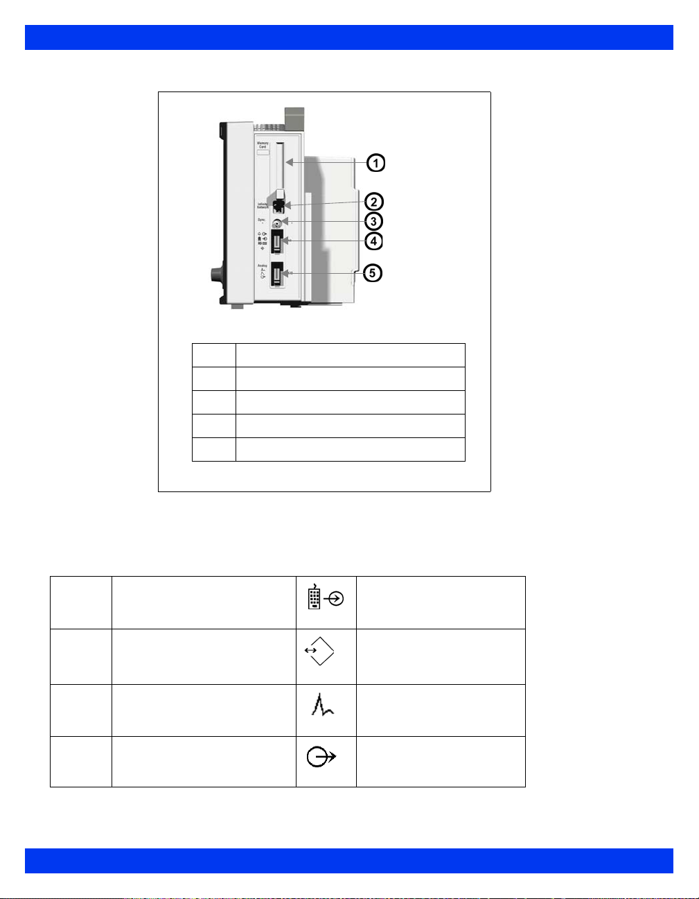
Monitor Right Side--Vista XL
1
2
3
4
5
PCMCIA slot
Network connector
QRS Sync connector
RS 232 connector (X8)
Analog connector (X10)
Device Markings
The following table describes the symbols on the monitor and its accessories:
&
@
Monitor on/off Remote keypad in
Battery-operated
equipment
Attention! Consult the
accompanying document
Defibrillator-proof equipment,
Type CF
RS 232
Analog out
Analog out
1-6 VISTA XL VF7
Page 29

Direct current Analog out
SYSTEM COMPONENTS
A
H
:
;
E
Danger: Risk of explosion if
used in presence of flammable
anesthetics
Isolated patient connection,
Type CF
0123
Complies with the European
Medical Device Directive 93/
42/EEC
Type BF, defibrillator
protected
Gas in Contains no latex material
Gas out Manufacturer’s lot number
Dispose of properly Certain cuff codes are
Manufacturing date REF Manufacturer’s reorder code
Alarm out Does not provide isolation
.
Push battery all the way into
compartment.
Close battery compartment
door.
This end up
Artery symbol and arrow
should be placed over
brachial or femoral artery.
ethylene oxide sterile.
between connected devices
∼
F
Monitor is receiving AC power Potential equalization
Observe WEEE (Waste
Electrical and Electronic
Equipment) disposal
requirements
terminal
VF7 VISTA XL 1-7
Page 30

1 I
NTRODUCTION
Modules
MultiMed and NeoMed Pods
The MultiMed houses connectors for ECG and impedance respiration leads, an SpO2
sensor, and a temperature probe.
The optional NeoMed, specifically designed for neonates, has connectors for a 3-lead
ECG cable set, an SpO
information.
HemoMed Pod
The monitor acquires invasive blood pressure (IBP) signals from a HemoMed pod.
For information, see Chapter 13, Invasive Blood Pressure. A HemoMed pod can also
acquire injectate and blood temperature for cardiac output (20-4).
etCO2 Module
The monitor processes etCO2 signals through an etCO2 module. For more information
on these optional devices, see Chapter 16, etCO2 (End-Tidal CO2) Monitoring.
sensor, and two temperature probes. See page 8-2 for more
2
Auxiliary Display Components
The following devices enable remote viewing of patient data.
Remote Display -- Allows you to view but not control monitor functions away from
the bedside. Dräger Medical strongly recommends that you use only approved video
monitors, otherwise the function of the monitor may be compromised. For a complete
list of approved video monitors, contact your Draeger Medical Systems, Inc. local
representative to obtain a catalog. Any use of non-approved monitors may
compromise the correct functioning of the device.
CAUTION: The Remote Display output on the IDS is not galvanically isolated. If you
use a video monitor other than one specified by Dräger Medical, it must comply with
IEC 60601-1. Upon installation, the installer must ensure that, in normal and single
fault conditions, the entire system meets the requirements of IEC 60601-1 and IEC
60601-1-1 (Medical Electrical Systems Standards). Refer to the video monitor’s
operating instructions to ensure that the interconnection is within its intended use as
specified by the manufacturer. Radiated and conducted emissions classi fication,
suitability for flammable locations and water ingress protection must be considered
based on the intended use of the system.
1-8 VISTA XL VF7
Page 31

Other Features and Components
z Remote Keypad--The optional Remote Keypad allows you to operate the
monitor from a distance. A rotary knob and fixed keys duplicate those of the
monitor, while a numeric keypad allows you to enter data. See page 1-15 for
more information.
z Export Protocol--Allows you to share data with other Dräger Medical an d
third-party devices (e.g., Clinical Information and Anesthesia Record Systems
and Data Loggers; see Dräger Medical publication Infinity RS-232 Export
Protocol Reference Booklet).
z Arrhythmia Classification Expert (ACE)--Detects cardiac events, reduces
false alarms, and filters out misleading or erroneous arrhythmia data.
z R50 Series Recorders--Produce alarm, timed, continuous, and trend
recordings. See Chapter 7, Recordings, for more information about R50 and
R50-N recorders.
z PCMCIA Card--Allows you to transfer data, upgrade software, store setups,
download setups, and store diagnostic logs.
z QRS Sync. Output--Allows you to synchronize defibrillators to the patient’s
heart beat during cardioversion.
z Balloon Pump Interface--Permits interaction with a balloon pump by
providing two analog output signals (ECG and ART).
SYSTEM COMPONENTS
VF7 VISTA XL 1-9
Page 32

1 I
NTRODUCTION
Power Sources
The Vista XL monitor can be powered by a hospital grade outlet with AC adapter, or
battery. In case of a line outage or disconnected cable, the monitor automatically
switches to battery power to ensure continued patient monitoring.
WARNING: Read “Safety Considerations” (page VII, in the
Overview of this Instructions fo Use) before connecting the
monitor to a power source.
CAUTION: Make sure all power cords are properly connected, or batteries may be
drained unintentionally.
Battery Power
The Vista XL monitor operates on an external, sealed
lead-acid battery and an internal lithium-ion battery . The
external battery, which can easily be replaced when
depleted, can power the monitor for 50 minutes. If it
runs low or you remove it from a monitor that has been
using battery power, the mo nitor automatically switches
to an internal battery, which can power the monitor for
180 minutes (See “Electrical Specifications” on page B-
7). When both batteries run low, the monitor sounds an
alarm, and a status message appears in the network message area. If both batteries are
depleted, the monitor turns off automatically.
The external battery fits into a compartment on the monitor’s left side. When depleted
or removed, replace it immediately or connect the monitor to a power supply.
Whenever the monitor is connected to power, the battery is charged (as indicated by
the battery charger LED on the front panel). The internal battery is charged first, then
the external battery.The following table illustrates the function of the battery charge
bar graph at the top of the screen:
NOTE: When AC power is disconnected, the battery
charge display can take up to 15 seconds to reflect
actual internal battery capacity and up to 60 seconds
to reflect actual external battery capacity
Insert
battery
here
Battery
1-10 VISTA XL VF7
Page 33

Battery Charge Display
Display Charge Left Action
Battery in use is fully charged. N/A
Battery in use is half full. Connect AC adapter.
POWER SOURCES
External battery is very low (<
25%).
External battery is depleted.
Internal battery is very low
(<25%).
Internal battery is depleted; <5
1
Monitor sounds single attention tone. 2Monitor sounds attention tone every 5
seconds.
minutes of power remaining.
1
2
Replace with fully charged
external battery.
Replace with fully charged
external battery.
Immediately connect monitor to
AC adapter. Replace external
battery.
WARNING: Actual time available on the internal battery can
be significantly reduced with worn out or defective batteries.
The ‘Internal Battery Percentage’ value on the Battery Status
screen is accurate only if the batteries are in normal work ing
condition.
CAUTION:
z DO NOT use the monitor for transport if the internal battery charge is at 25%
or less, unless you are using a fully charged external battery.
z High temperatures may adversely affect batteries. For optimal performance,
charge and use the external batteries at temperatures below 35°C (95°F).
z Follow local regulations for safe disposal of batteries. To prevent fire or
explosion, never dispose of batteries in fire.
z Use only batteries that are provided by Dräger Medical. The use of non-
approved batteries may damage the device.
VF7 VISTA XL 1-11
Page 34

1 I
NTRODUCTION
Charging the Batteries
Before using the Vista XL monitor for the first time, charge the internal battery for a
maximum of 4.5 hours and the external battery for 3.5 hours. When the monitor
receives DC power, batteries recharge automatically.
The optional SLA Battery Charger can charge four fully depleted external batteries
simultaneously in approximately 3.5 hours. To start a fast-charge, insert the batteries
into the slots of the battery charger with the metal contacts facing down.
NOTE:
z T o retain charge during transport, leave the monitor connected until you are
ready to move the patient. Reconnect the monitor immediately after transport.
Dräger Medical recommends replacing lead-acid battery after 18 months of
continued use.
z Dräger Medical recommends replacing the internal lithium ion battery after 24
months of use.
z To prevent premature depletion, recharge batteries immediately after
discharging them. Lead-acid batteries degrade rapidly if left several days in an
uncharged state.
z In storage, lead-acid batteries discharge slowly over time and may become
depleted after several months. Batteries stored for use with the monitor should
be recharged every six months.
CAUTION: This charger is intended for charging the monitor batteries only. Do not use
other chargers or batteries.
When the monitor receives DC power, batteries recharge automatically.
1-12 VISTA XL VF7
Page 35

Getting Started
Turning the Monitor On and Off
To turn the monitor on:
GETTING STARTED
z Press the power key (
), located on the bottom left of the Vista XL
'
monitor's front panel . The monitor turns on the power indicator light, lights
up the screen, performs a self-test, and displays the main screen.
To turn the monitor off:
z Press and hold the power key (O) for two seconds. The power indicator
light turns dark, and the monitor emits a power-down tone.
Accessing the Main Screen
After you power up the monitor, the main screen appears. To return to the main screen
from a menu or other display:
z Press the Main Screen fixed key, located just above the rotary knob on the front
panel of the monitor. The main screen appears, as shown in the following
illustration.
1
2
3
4
Network message
Parameter boxes
Waveforms
Local message
VF7 VISTA XL 1-13
Page 36

1 I
NTRODUCTION
The standard monitor provides five waveform channels with adjacent parameter
boxes. Channels can be added to display up to six waveforms. The bottom channel can
be used to display additional parameter boxes (see “Bottom Channel” on page 2-7).
Parameter boxes show values, alarm limits, and special icons for selected parameters.
Parameters and their associated waveforms are color-coded for easy recognition.
NOTE:
z You can access parameter setup menus by scrolling through the parameter
boxes using the rotary knob and clicking on the parameter you wish to
configure.
z See “Quick Reference -- Main Menu Setup” on page 2-3 to access parameter
setup menus.
NOTE:
z You can change the default color coding for each parameter by accessing the
Parameter Colors menu. (See page 2-19)
z For a list of default parameter colors, see Quick Reference -- Parameter Colors
Menu on page 2-20.
Messages appear along the top of the screen in either the
Network Message (right) area. When there is no local message, the monitor displays
Local Message (left) or
the patient’s name and bed label. When there is no network message, the monitor
displays the date and time.
Using the Rotary Knob
The rotary knob allows you to browse menus, choose settings, and execute
menu functions. Scroll through menu items by turning the knob. Press the
knob (or click) to confirm.
To set or execute menu items with the rotary knob:
1. Select the required function by dialing the knob.
2. Press the knob and click to confirm your selection. A list of choices appears
or the field switches to its alternate value, e.g.,
You can also use the rotary knob to enter letters or numbers.
ON to OFF.
1-14 VISTA XL VF7
Page 37

GETTING STARTED
1. Click on a fiel d (e.g., Physician). The monitor displays a data-entry screen
similar to the following:
2. Use the rotary knob to select each character or number, then click to confirm.
Use the control buttons at the bottom of the screen for editing.
3. Click on
Accept to confirm the entire entry or on Cancel to exit the data entry
screen.
Remote Keypad
The remote keypad has all of the fixed keys that are on the monitor and additional
keys that perform the following:
Trends — Displays trend graphs
Freeze — Freezes waveform display
Calcs. — Activates Calculations menu
All ECG — Displays Show All Leads screen
Remote View — Displays Remote View menu
Recall Setup — Displays Restore Setups menu
View+ — Toggles from monitor to secondary (display) screen
To connect the remote keypad to the Vista XL monitor:
Plug one end of the keypad cable into the keypad and the other into the connector
marked RS232 on the right side of the monitor.
VF7 VISTA XL 1-15
Page 38

1 I
NTRODUCTION
Menu Access
There are two ways of accessing the menus. The Fast Access menu allows you to open
commonly used menus quickly. The Main Menu lists the primary menus (Patient
Setup, Monitor Setup, etc.), which allow you to access other menus.
Fast Access Menu
The Fast Access menu accesses the following submenus and screens dire ctly:
Fast Access Item See page Fast Access Item See page
Remote View 3-10 Calculations 14-1
OxyCRG (Neonatal only) 11-10 Show All Leads 8-15
Alarm History 5-15 OR 2-11
Trend Graphs 6-4 Reports 7-11
Trend Table 6-7 Split Screen 2-8
Event Recall 1-19
Drug Dosage 14-7
To open the Fast Access menu:
z Press the Fast Access fixed key on the front of the monitor.
You can access many of these menus by selecting
Review on the Main Screen menu.
See page 2-4 for more information.
Main Menu
The Main Menu allows you to execute certain functions and access others. Icons are
used to identify menu items:
z Page icon (e.g., Restore Setups) -- Accesses submenu
z Arrow icon (e.g., Review) -- Displays another column
z No icon (e.g., Standby) -- Executes function
To display the Main Menu:
1. Press the
2. Click on a page icon next to a heading ( ) to open a Main Menu submenu or
on an arrow icon ( ) to display another column of Main Menu options (see
page 2-3 for detailed information on configuring the Main Menu).
Menu fixed key. The primary list of Main Menu options appears.
1-16 VISTA XL VF7
Page 39

DATA ARCHIVE APPLICATIONS
Fixed Keys
Fixed keys on the monitor front panel allow you to perform commonly executed
functions. .
CAUTION: Moisture under the front panel can damage the electric circuits and
compromise key function. For safe cleaning instructions, see page 21-1.
Fixed
Key
Alarm
Silence
Alarm
Limits
All
Alarms
Off
Fast
Access
Description
Silences the active alarm
tone for one minute
Opens a table from which
you can set upper and lower
alarm limits
Suspends all alarms for a
pre-selected time or cancels
the suspension
Displays the Fast Access
Menu
Fixed
Key
Main
Screen
Menu Activates the Main Menu
NBP
Start
Stop
Record Toggles a timed recording
Description
Activates the main screen
Starts or stops non-invasive
blood pressure (NBP)
measurement
on or off
Control Buttons
Control buttons are located along the bottom of the various screens, trend tables,
graphs, loop displays, etc. They permit additional screen-specific settings.
Data Archive Applications
The monitor can store events, alarms and trends automatically or at the user’s request,
depending on the type of information you wish to store. Some events are
automatically recorded and stored. The monitor automatically stores alarm conditions
and arrhythmia events that you have configured for storage in the Alarm Limits table
(see page 5-5) and in the Arrhythmia setup table (see page 9-6).
NOTE: You cannot disable event storage for asystole and ventricular fibrillation calls.
The monitor stores these events automatically.
You can access archived information in one or more of the following databases:
z Trends
VF7 VISTA XL 1-17
Page 40

1 I
NTRODUCTION
z Calculations
z Alarm History
z Event Recall.
Each database indicates the time of the data capture and parameter values and/or
waveforms active at the time of capture. Trends, Calculations, and Alarm History are
discussed in the following chapters (Event Recall and Storage is explained later in this
section.):
z Trends -- See Chapter 6, Trends. Stored events are marked with the time and
date of capture as follows:
z Calculations -- See Chapter 14, Calculations.
z Alarm History -- See Chapter 5, Alarms.
Storing Events
Trend Table -- An icon ( ) over the time line marks manually stored events
only. (Automatically stored alarms and arrhythmia calls are not marked in the
Trend Table.)
Trend Graphs -- A small yellow vertical line at the top of the screen marks
manually and automatically stored events.
Automatic Storage
The monitor stores events automatically, if you have first correctly configured the
Alarm Limits and Arrhythmia Setup tables.
You can enable individual parameter alarms in the
Limits and/or the ARR Setup screens. Configure event storage in the
by selecting
Store or Str./Rec.
Alarms column of the Alarm
Archive column
1-18 VISTA XL VF7
Page 41

DATA ARCHIVE APPLICATIONS
Event Recall
The monitor stores monitoring data (waveforms and parameter values), alarm
conditions, and arrhythmia events on the Event Recall screen. You can view up to 50
stored events, each containing 20 seconds of data, with associated date and time
stamps.
Events are stored on a first-in, first-out basis. When event storage is full, the monitor
deletes the oldest events to make room for new ones. All stored events are deleted
whenever you discharge a patient, reset the monitor, or temporarily lose power.
To access the Event Recall screen:
1. Press the
2. Click on
Fast Access fixed key.
Event Recall to display the Event Recall screen.
VF7 VISTA XL 1-19
Page 42
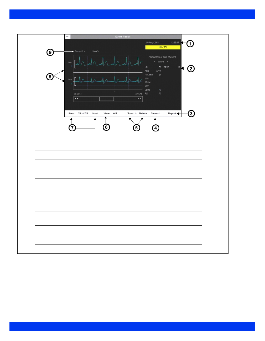
1 I
NTRODUCTION
1
2
3
4
5
6
7
8
9
Time of capture
Parameter values at time of capture
Print report
Requests recording
Saves/Deletes events
View: All - displays all stored events; Manual - displays manually
stored events; Alarm - displays alarm events only; BRDY - displays
bradycardia events only; Desat - (Neonatal only) displays desaturation
events only
Parameter display: Prev displays previous set of (2) parameters.
Next displays next set of (2) parameters
Parameter labels of displayed waveforms
Waveform delay and speed
1-20 VISTA XL VF7
Page 43

DATA ARCHIVE APPLICATIONS
Navigating the Event Recall Screen
To scroll forward and back through 20 seconds of waveform data, click on arrows at
either side of scroll bar at the bottom of the screen.
To scroll through the list of parameter values at the time of data capture, click on the
arrow keys above the list of parameters at the right of the screen:
To scroll through the waveforms displayed at the time of data capture, click on the
Prev (Previous) and Next control buttons under waveform display.
VF7 VISTA XL 1-21
Page 44

1 I
NTRODUCTION
Help Functions
You can display a short description of currently highlighted functions at the bottom of
all active menus by enabling context-sensitive help:
1. Press the
2. Click on
3. Open the
4. Select
Menu fixed key to open the Main Menu.
Monitor Setup. Another column of options appears.
Display Options menu by clicking on that heading.
Help Line Display and click to choose ON.
Additional information about the monitor is available in the Main Help menu.
1. Press the
2. Click on
Menu fixed key.
Help. The Main Help Menu appears.
Click on the appropriate selection in the table below.
Menu Item Description
Locked Options Displays active software options currently installed on the
Fixed Keys De sc rib es f un cti on s of Fi xe d Key s
monitor
1-22 VISTA XL VF7
Page 45

Chapter 2 Monitor Setup
Overview............................................................................................................................2
Configuring the Monitor...................................................................................................2
Main Menu Setup........................................................................................................2
Quick Reference -- Main Menu Setup.............. .... ... ... ... .... ........................................3
Setups Management.......................................................................................................10
Specialty Menus..............................................................................................................11
OR Mode ............... ... .... ... ............................................................................. .... ... ... ...11
Unit Manager ............... ... ... ... .... ... ... ... .... ... .......................................... ... ...................13
Biomed......................................................................................................................17
Parameter Colors .... .......................................... .... .......................................... .........19
Page 46

2 M
ONITOR SETUP
Overview
This chapter describes how to configure the monitor.
Configuring the Monitor
Main Menu Setup
The Main Menu allows you to access submenus, display screens, and execute certain
monitor setup functions.
1. Press the
2. Click on a page icon ( ) to open a Main Menu submenu,
or
Click on arrow icon ( ) to display another column of submenu options.
3. Click on desired setting to execute functions or access further submenus.
4. Click on
left corner of the screen to return to prior menu or screen.
Menu fixed key to display the Main Menu.
Exit at the bottom of a submenu list or on the white arrow in upper
2-2 VISTA XL VF7
Page 47

CONFIGURING THE MONITOR
Quick Reference -- Main Menu Setup
The Main Menu
Menu Item Description Available Settings
Cursor Tool Provides access to Cursor Tool
The Cursor Tool Submenu
This submenu allows you access to the following functions.
Setup Opens Cursor Tool Setup menu. • Waveform (Up to 3.)
Horizontal
Cursor
(One for each
waveform on
display)
1
Cursor value is displayed only if a scale is associated with the waveform.
Waveform scales are the same as parameter main display.
submenu, which allows user to
select three waveforms
displayed with horizontal cursors
and a vertical cursor.
Displays a horizontal cursor.
User can scroll up and down
each waveform.
NOTES:
• Cursor value is displayed
• Cursor and value are on display
until user exits window.
• Buttons remain ghosted until
user presses Stop key.
To EXIT the Cursor tool:
• Press/click the Rotary Knob to
exit cursor control.
or
• Press the Main Screen fixed
key.
1
• Setup
• Horizontal Cursor
•Stop
• Hemo/Calcs
• Vertical Cursor
Note: See Cursor Tool Submenu,
below.
NOTE: In 4 channel mode, maximum of
2 waveforms.
• Sweep Speed
• 6.25 mm/sec.
• 12.5 mm/sec.
• 25 mm/sec. (Default)
• 50 mm/sec.
N/A
.
Stop Halts scrolling of all waveforms in
cursor tool display and un-ghosts
Horizontal and Vertical Cursor
buttons.
N/A
VF7 VISTA XL 2-3
Page 48

2 M
ONITOR SETUP
The Main Menu
Menu Item Description Available Settings
Hemo/Calcs Opens the hemo/calcs screen.
NOTES:
• Button is ghosted unless a
license is present.
• Advanced calcs menu is
available if option is installed.
Vertical
Cursor
Review Provides access to submenus of
Displays a vertical cursor. User
can scroll forward and backward
across all waveforms.
NOTES:
• Cursor has no value.
• Cursor remains on display until
user exits window.
• Buttons remain ghosted until
user presses Stop key.
To EXIT the Cursor tool:
• Press/click the Rotary Knob to
exit cursor control.
or
• Press the Menu, Main Screen,
Alarm Limits, or Fast Access
fixed key.
the Main Menu display
N/A
N/A
• Click on Review to open the
following submenus and
displays: Alarm History, Trend
Graphs, Trend Table, Event
Recall, Calc. Results,
OxyCRG (neonatal mode
only), Show All Leads, and
Reports.
• Click on Exit to return to the
first column of the Main Menu.
2-4 VISTA XL VF7
Page 49

CONFIGURING THE MONITOR
The Main Menu
Menu Item Description Available Settings
The Patient Setup Submenu
This submenu allows you to configure the following functions.
Patient
Category
Pressure
Labels
Parameters Accesses parameters’ setup
Alarm Limits Opens alarm limits table N/A; see page 5-5.
Determines availability of
monitoring features such as
apnea detection (neonates only)
and ventilation
Notes:
• When you click on a setting, a
popup message warns you that
algorithms and alarm settings
are about to change. In the
popup window, click again on
the category of your choice.
• If you change a patient’s
category, the weight selection
is cleared and must be selected
again.
Assigns IBP pressure channel
labels
See Chapter 13, Invasive Blood
Pressure, for detailed
information.
menus
•Adult
• Pediatric
• Neonatal
ART, PA, CVP, LA, LV, RV, RA,
ICP, GP1, GP2
• Click on one of the listed
parameters to access its setup
menu: (e.g., ECG, ARR, ST,
ART, PA CVP, RA, SpO
RESP, etCO2, C.O., TEMP,
GP1, GP2, O2, fiO2, ).
Note: There may be other
possible selections depending
on the monitor configuration and
connected devices.
• Click on Exit to return to the
first column of the Main Menu.
, NBP,
2
VF7 VISTA XL 2-5
Page 50

2 M
ONITOR SETUP
The Main Menu
Menu Item Description Available Settings
The Monitor Setup Submenu
Main Screen
This submenu allows you to lay out the main screen display by configuring the
functions outlined below. To access second page of the Main Screen menu, click on
the down arrow at the bottom of the screen. Click on the up arrow to return to the
Main Screen menu first page.
Parameter
Priority
Allows you to modify the order of
parameters displayed on the
Main Screen
Notes:
• Parameters must be assigned
a priority; whether they appear
on the main screen depends on
their priority and on the number
of channels configured to
display waveforms (see Max.
Channels).
• In Automatic display mode,
connected parameters are
displayed according to their
priority in the Parameter
Priority list. If all available
channels are filled, a higher
priority parameter will NOT
“bump” lower priority parameter
boxes off the Main Screen
when the associated device is
connected. In order to display
the parameter, the user must
double-click on the parameter
in the Parameter Priority list.
• In OR Mode, if all avai lable
channels are filled, a higher
priority parameter will “bump”
lower priority parameter boxes
off the Main Screen when the
associated device is
connected.
To change the display order of a
parameter whether or not the
associated device is connected:
1) Scroll to Display Mode.
2) Select Manual.
3) Click on Parameter Priority
to highlight the first listed
parameter.
Note: Parameters are
numbered according to their
priority. The display is color
coded: A green parameter label
indicates that the associated
parameter device (e.g., an NBP
hose/cuff) is connected to the
monitor. A white label indicates
that the device is not connected.
4) Scroll the list to the
parameter you wish to move
and click.
5) Move the parameter to its
new place using the rotary knob.
6) Click to confirm the
parameter’s new position on the
list.
7) Click again to return to
Parameter Priority.
8) Scroll to the arrow at the
upper left corner of the menu to
exit, or continue to set up other
Main Screen submenu
functions.
Max.
Channels
Determines number of waveform
channels and parameters
displayed
• Click on 4, 5, 6, 7, or 8.
Note: The number of
waveforms you can display
depends on the software option
you have installed.
2-6 VISTA XL VF7
Page 51

CONFIGURING THE MONITOR
The Main Menu
Menu Item Description Available Settings
Bottom
Channel
ECG
Channels
ARR
Monitoring
ST Monitoring Enables and disables ST
RESP
Monitoring
Display Mode Reduces Main Screen clutter by
Configures bottom waveform
channel to display waveform or
parameter boxes
Determines the number and
format of ECG waveforms
displayed
Selects the Arrhythmia mode
(For detailed information, see
page 9-1.)
Monitoring (For detailed
information, refer to Chapter 10,
ST Monitoring.)
Enables and disables respiration
monitoring
(For detailed information, refer to
Chapter 11, Respiration.)
displaying only parameters
associated with a connected
device
(see Parameter Priority, page 2-
6)
• Click on Waveform to display
a waveform in the bottom
channel.
• Click on Parameters to
display 3 parameter boxes
instead of a waveform in the
bottom channel.
Click on the following settings:
• ECG1 -- Displays the primary
ECG signal
• ECG1 & 2 -- Displays 2
signals
• ECG1 & 2 & 3 -- Displays 3
signals
• Cascade -- Cascades ECG1
data into second channel
• Click on OFF to disable
arrhythmia monitoring.
• Click on FULL to enable full
arrhythmia monitoring.
• Click on BASIC to enable
basic arrhythmia monitoring.
• Select ON to enable ST
monitoring.
• Select OFF to disable ST
monitoring.
• Select ON to enable
respiration monitoring.
• Select OFF to disable
respiration monitoring.
• Click on Manual to display all
parameters and assign them a
priority on the Parameter
Priority screen.
• Click on Automatic to display
active parameters only.
VF7 VISTA XL 2-7
Page 52

2 M
ONITOR SETUP
The Main Menu
Menu Item Description Available Settings
Split Screen Reserves a portion of the main
Display Options
This submenu allows you to access and modify waveforms and other display
features
by configuring the following functions.
Monitoring
Sweep Speed
Respiratory
Sweep Speed
Pressure
Overlap
Pressure
Common
Scale
Monitor
Brightness
SC 9015
Brightness
Help Line
Display
screen for display of trend
graphs
Determines waveform speed
Higher sweep speed “moves”
waveform more quickly.
Allows you to set monitoring
sweep speed for Respiration
waveform independently
Displays up to 4 overlapping IBP
waveforms in single oversized
channel
Overlapped waveforms share a
common zero point, but each
retains original scale
configuration (see page 13-11).
Displays pressure waveforms
with a common scale, making it
easier to compare them
Sets brightness of monitor • Click on Auto (ambient light),
Sets brightness of SC 9015
Shows contextual help line at
bottom of menu
Click on one of the following:
•OFF
• 60 Min Trends
• 10 Min Trends
• Click on 6.25, 12.5, 25, or 50
mm/s.
• Click on 6.25, 12.5, 25, or 50
mm/s.
• Select ON to display IBP
waveforms in overlapping
format.
• Select OFF to cancel display
of waveforms in overlapping
format.
• Click on 5, 10, 15, 20, 25, 30,
40, 50, 75, 100, 150, 200, 250,
300 mmHg, or OFF.
20, 40, 60, 80, or 100%.
• Select ON to display help.
• Select OFF to cancel display.
Parameter
Units Display
Displays unit of measure in
parameter boxes
• Select ON to display units.
• Select OFF to cancel display.
2-8 VISTA XL VF7
Page 53

CONFIGURING THE MONITOR
The Main Menu
Menu Item Description Available Settings
Monitor Options
This submenu allows you to configure the following functions.
Date & Time Sets the date and time displayed
Speaker
Volumes
Trend Setup Allows you to configure trend
in the lower right potion of the
main screen
Notes:
• An intern al battery powers the
monitor’s clock even when the
monitor is turned off.
• This option is not available
when the monitor is connected
to network, since network date
and time are set at the central
station.
• Changing the time does not
affect other time-related
functions such as timers and
time stamps.
Allows you to set the volume for
alarms, pulse tones, and
attention tones
display
To set the monitor date and
time:
1) Click on Date & Time.
2) Click on Current Date. A
data entry screen appears.
3) Click on Day, scroll to the
correct date, and click.
4) Repeat Step 3 for Month and
Year.
5) Click on Accept to confirm or
on Cancel to return to
submenu.
6) Click on Current Time to set
the time, using the same
method described in steps 3
and 5.
• Click on Alarm Volume to set
the volume of alarms (10-
100% in increments of 10).
• Click on Pulse Tone Volume to
set the volume of the pulse
tone (OFF-100% in increments
of 10 after 5).
• Click on Attention Tone
Volume to set the volume of
attention tones (OFF-100% in
increments of 10 after 5).
• Submenu; see Chapter 6,
Trends, for detailed
information.
Recordings Allows you to configure and
assign recorders
Biomed Provides access to technical and
clinical logs and service menus
Unit Manager Allows the unit manager,
physician or head nurse to
configure monitoring functions
for the clinical staff
OR Configures monitor to meet the
special needs of the operating
room environment
• Submenu; see Chapter 7,
Recordings, for information.
• Submenu; see page 2-17.
• Submenu; see page 2-13.
• Submenu; see page 2-11.
VF7 VISTA XL 2-9
Page 54

2 M
ONITOR SETUP
Setups Management
You can save and restore the current patient and monitoring settings.
Setups Management
Menu function/
item
Configuring Setups
To save, or resto re setups, configure them as shown in the referenced pages.
Main screen display Main Screen menu Page 2-6
Parameters Parameter Setup menu(s) Page 2-5
Alarms Alarm Limits Table Page 5-5
Arrhythmia calls Arrhythmia Setup Table Page 9-6
Trends Trend Setup
Naming and Renaming Setups
Follow these procedures to name or rename the setups you have configured.
Accessing
the Unit Manager
Menu
Description Reference/Procedures
Note: For more information,
see parameter chapters.
Page 6-2
Trend Graphs
Trend Table
Allows you to modify setups
on the password-protected
Unit Manager menu
Note: For information on
other Unit Manager
functions, see page 2-13.
Page 6-4
Page 6-7
To enter the password:
1) Press the Menu fixed key to
display the Main Menu.
2) Click on Monitor Setup.
3) Click on Unit Manager. A
data entry box appears.
4) Click on each number of the
appropriate password. If you
make a mistake, click on
Backspace and try again.
5) Click on Accept to open the
Unit Manager menu.
Restoring Factory Defaults
Consult your Biomed to restore settings shipped with the monitor to their original
configuration. For detailed information on password-protected Biomed setup
functions,
please consult service and installation documentation.
2-10 VISTA XL VF7
Page 55

SPECIALTY MENUS
Specialty Menus
OR Mode
OR mode is designed specifically for the operating room environment, allo wing you
instant access to a particular set of parameters and functions. In addition, you can
disable audible alarms without affecting visual alarms, even when the monitor is not
connected to a network.
WARNING: Do not set monitor to OR mode outside operating
room environment because OR alarms behave d ifferently than
regular alarms.
NOTE: Life Threatening and Serious alarms do not latch when OR mode is ON.
To access the OR menu:
1. Press the
2. Click on
Fast Access fixed key.
OR to display the OR menu.
Quick Reference Table -- OR Menu
OR Function Description Settings
The OR Menu
OR Activates OR menu
functions
Note: This function is a locked
option. It is installed at the
time of purchase from
perioperative care unit or it
can be installed locally by
Dräger Service or local
Biomed.
Cardiac Bypass Configures monitor for use
during cardiac surgery
• ON -- OR functions are
enabled.
• OFF -- The monitor reverts to
normal functions;
Cardiac Bypa ss, and NBP
Chime are ghosted.
• ON -- Suspends all patientmonitoring alarms, NBP
interval measurements, and
arrhythmia detection.
• OFF -- The monitor reverts to
normal functions.
VF7 VISTA XL 2-11
Page 56

2 M
ONITOR SETUP
OR Function Description Settings
NBP Chime Enables and disables
Alarm Volume Sets alarm volume
Large IBP-Mean
Display
Attention Tone
Volume
HR Source Derives heart rate from
Filter Determines sensitivity to
ARR Monitoring Determines number of
attention tone for NBP
measurements
(For more information, see
Chapter 12, Non-Invasive
Blood Pressure.)
Note: Minimum setting is
OFF if OR is enabled or if
monitor is connected to a
central station. Minimum
setting is 10% if OR is
disabled.
Determines the relative size
of the mean pressure value
in invasive pressure
parameter boxes
Sets attention tone volume
Notes:
• Minimum setting is 5% if
OR is enabled or if monitor
is connected to a central
station. Minimum setting is
10% if OR is disabled.
various sources
Note: This function is useful
during electrosurgery, when
artifact makes ECG channel
unavailable. See page 8-20
for more information.
noise, artifact, and other
signal distortion
Note: The ESU setting
automatically disables pacer
detection. See page 8-17 for
detailed information on
Filter and its settings.
arrhythmia events you can
monitor
Note: For detailed
information, see page 9-1.
• ON -- Monitor sound s an
attention tone when NBP
measurement is complete.
• OFF -- No tone sounds when
you complete an NBP
measurement.
• 20 - 100% in increments of 10
• OFF or 10%
• ON -- Enlarges mean IBP
display
• OFF -- Reduces mean IBP
display to match systolic and
diastolic display size
• 20 - 100% in increments of 10
• OFF or 5%
Click on one of the following
settings to determine the Heart
Rate source:
•ECG
•ART
•SpO
2
•AUTO
•OFF
• ESU
• Monitor
•OFF
•Basic
•Full
Pulse Tone
Volume
Sets pulse tone volume
(See page 2-9.)
• Off - 100%
2-12 VISTA XL VF7
Page 57

SPECIALTY MENUS
Unit Manager
The Unit Manager menu lets supervisory personnel configure monitoring functions
for the clinical staff. Access to this menu is restricted by a password. To open the Unit
Manager menu:
1. Press the
2. Click on
Menu fixed key to open the Main Menu.
Monitor Setup.
3. Click on Unit Manager. A data entry box appears.
4. Scroll through the numbers and click successively on the single digits of the
clinical password. If you make a mistake, click on
5. Click on
Accept to open the Unit Manager menu. Available functions are
Backspace and try again.
described in the table that follows.
The Unit Manager Menu
Menu Item Description Available Settings
Alarm Control Submenu
The
This menu allows the unit manager to configure alarm annunciation. Open the Unit
Manager menu, click on Alarm Control, then follow the procedures outlined in this
table to execute the indicated functions.
All Alarms OFF
Key
All Alarms OFF
Time
Extend All
Alarms OFF
Note: This
selection will only
appear if monitor
is configured to
support this
feature. Contact
your biomed for
more information.
Determines whether clinical
personnel can suspend alarms
by using the All Alarms Off
fixed key on the front of the
monitor
Sets alarm suspension time
WARNING: Never leave
a patient unattended during
an indefinite alarm
suspension (e.g., after
selecting No Timeout).
Always enable the alarms
again as soon as possible.
Determines whether clinical
personnel can use the All
Alarms Off fixed key to extend
the All Alarms Off time.
• ON -- Pressing All Alarms Off
fixed key suspends alarms.
• OFF -- Pressing All Alarms
Off fixed key triggers an error
tone.
• 1, 2, 3, 4, or 5 min -- A timer at
the top of the screen
indicates
the amount of time
remaining in All Alarms
OFF Time.
• No Timeout -- Alarms
suspended indefinitely; no
timer appears.
• Enabled
• Disabled (de fault)
VF7 VISTA XL 2-13
Page 58

2 M
ONITOR SETUP
The Unit Manager Menu
Menu Item Description Available Settings
Alarm
Validation
Note: When
Alarm Validation
is ON, the time to
alarm from the
onset of a limit
violation will equal
the time for
detection + the
designated Alarm
Validation signal
delay. For HR,
this time may
exceed AAMI
EC13 requirement
of a maximum of
10 seconds.
SpO2 Alarm
Delay
ASY/VF Alarms
NBP/SpO2
Interlock
V ali d ates alarm conditions to
limit nuisance alarms due to
artifact or motion/movement by
delaying time to alarm.
Alarm validation times are:
Upper Lower
HR 6 sec. 6 sec.
RESP 14 sec. 14 sec.
IBP 4 sec. 10 sec.
SpO
PLS 6 sec. 10 sec.
6 sec. 10 sec.
2
1
1
SpO2* 4 sec. 4 sec.
PLS* 4 sec. immediately
All Other Parameters
immediately
1
(See “SpO2 Alarm Delay”.)
Validates an SpO2 alarm
condition by requiring that
violation persist for 10 seconds
(lower limit) before sounding an
alarm.
Note: Alarm validation must be
turned ON.
Allows user to prevent disabling
of ASY and VFIB alarms.
Allows user to render SpO2
alarm inactive when NIBP
measurement is in progress.
WARNING: Visually
ensure that NIBP cuff is
on the same arm as SPO
sensor. The monitor will
not automatically detect
that NIBP cuff and SPO
sensor are on the same arm.
2
• ON -- Enables Alarm
Validation
• OFF -- Disables Alarm
Validation
• ON -- SpO2 or PLS lower limit
alarm condition annunciated
after it persists for a period of
10 seconds.
• OFF -- SpO
alarm condition is not validated
or PLS lower limit
2
before annunciation.
• Always ON -- ASY and VFIB
alarms are always active.
• Follow HR Alarms (default) -ASY and VFIB alarms follow
HR alarm settings.
WARNING: When HR
is “OFF” and ARR
Alarm
monitoring is “OFF”,
ASY/VF alarms do not
sound.
• ON -- SpO2 alarm is inactive
when NBP measurement is
taken.
• OFF (default) -- SpO
active when NBP
measurement is taken.
2
alarm is
2
2-14 VISTA XL VF7
Page 59

The Unit Manager Menu
Menu Item Description Available Settings
SPECIALTY MENUS
MIB Alarm
Control
Allows user to activate/
deactivate MIB disconnect
alarm.
• ON (default) -- MIB disconnect
alarms are active.
• OFF -- MIB disconnect alarms
are inactive.
Remote View
Display
Allows user to set Remote View
behavior when Remote View is
displaying telemetry ECG.
• Always ON -- Local bed alarm
will not cause remote view
feature to “pull down” remote
bed display.
• Pull Down on Alarm (default)
-- Local bed alarm will cause
remote view feature to “pull
down” remote bed display.
Audio Alarm
Reminder
Allows user to set a reminder
when alarm volume is turned
OFF.
• ON (default) -- When Alarm
Volume is turned OFF, a
reminder tone sounds every 30
sec. at 50% volume.
Note: For OR Mode: at the end of
the countdown period (alarm
silence or alarm off), if the
alarm condition is still active,
the parameter box will flash
and an appropriate SER, L T,
or ADV reminder tone (at
50% volume) sounds every
30 sec.
• OFF -- There is no reminder
tone when Alarm Volume is
turned OFF.
SpO
2
Delay
Alarm
Validates an SpO2 alarm
condition by requiring that
violation persist for 10 seconds
(lower limit) before sounding
an alarm.
Note: Alarm validation must be
turned ON.
• ON -- SpO2 or PLS lower limit
alarm condition annunciated
after it persists for a period of
10 seconds.
• OFF -- SpO
alarm condition is not validated
or PLS lower limit
2
before annunciation.
The Code Setup Submenu
This menu allows the unit manager to configure the monitor for quick emergency
response. Open the Unit Manager menu (page 2-13), click on Code Setup, then
select and execute functions as described in this table. For more information, see
page 5-4.
Continuous
Record
Note: If no recorder is
available, the recording
request remains pending for
later printing. The default
setting is Yes.
• Yes -- Allows continuous
recording when you press the
Code key on the remote
keypad.
• No -- No recording can be
initiated when Code key is
pressed.
VF7 VISTA XL 2-15
Page 60

2 M
ONITOR SETUP
The Unit Manager Menu
Menu Item Description Available Settings
Continuous
NBP
Alarm Volume
OFF
Menu Setup Submenu
The
Menu Setup Determines amount of time
The Drug List Setup Submenu
This menu allows the unit manager to store up to 44 types of drugs and their
dosages for use during drug calculations. Open the Unit Manager menu (page 2-13),
click on Drug Setup, then follow the procedures outlined on page 14-9.
Note: You must attach the
NBP cuff and display the NBP
parameter box before
requesting NBP
measurements. The default
setting is No.
The default setting is No. • Yes -- Allows you to lower the
menus and screens remain
displayed
Note: This setting determines
menu display time in Remote
View also.
• Yes -- Allows continuous NBP
measurements when you
press the Code key on the
remote keypad.
• No -- No NBP measu r ements
can be initiated when Code
key is pressed.
alarm volume (to 10% on nonnetworked monitors) or silence
alarms completely (OFF on
networked monitors) when you
press the Code key on the
remote keypad.
• No -- Alarm volumes are not
affected when the Code key
on the remote keypad is
pressed.
1) Click on Menu Setup.
2) Click on Menu Time Limit.
3) Click on one of the following:
• ON -- Active menus and
screens display for a limited
time only (approximately 5
minutes).
• OFF -- Menus and screens
remain displayed until you
cancel them or select another
display.
2-16 VISTA XL VF7
Page 61

SPECIALTY MENUS
The Unit Manager Menu
Menu Item Description Available Settings
The Change Password Submenu
This feature allows you to change the password of the Unit Manager menu.
Open the Unit Manager menu (page 2-13), click on Change Password, then follow
the procedures outlined in this table.
1) Scroll through the numbers and click successively on the single digits of the
clinical password. If you make a mistake, click on Backspace and try again.
2) Click on Accept to confirm the new password.
The Pacer Detection Mode Submenu
Open the Unit Manager menu, click on Pacer Detection Mode, then foll ow the
Basic (default)
Advanced Sets Pacer Detection
This feature allows you to set pacer detection function.
procedures outlined in this table.
Sets Pacer Detection selections
in the ECG options submenu to
ON/OFF only.
selections in the ECG options
submenu to ON/OFF/Fusion.
•N/A
•N/A
Biomed
The Biomed menu addresses technical aspects of the monitor. To open the Biomed
menu:
1. Press the
2. Click on
3. Click on
Menu fixed key to open the Main Menu.
Monitor Setup.
Biomed.
Quick Reference -- Biomed Menu
Menu Item Description Settings/Procedures
Logs Submenu
The
This menu displays clinical and technical diagnostic records. Open the Biomed
menu and click on Logs, then follow the procedures described in this table.
VF7 VISTA XL 2-17
Page 62

2 M
ONITOR SETUP
Menu Item Description Settings/Procedures
Component Log The monitor maintains read-
Status Log Displays information about
Diagnostic Log Captures data about
FE Diag. Log Captures and displays data
Copy All Logs Downloads status logs and
Print Log Prints an expanded version
Service Submenu
The
The Service menu is password-prote c te d
and intended for the hospital’s biomedical or Dräger Medical service personnel
only.
Test Pulse
Test Pulse Tests ECG signal clarity and
only logs for principal
components or devices.
These logs include a part
and revision numbers, serial
numbers, software version,
and compatibility
information.
your current software and
hardware versions
hardware and software
performance relating to the
monitor’s operation
about front-end performance
related to the monitor’s
operation
diagnostic logs to a memory
card
of the Diagnostic Log to an
I
NFINITY network laser printer
display
1) Scroll to the component
you wish to inspect and click
on it. The log appears with
the exit arrow already
selected.
2) Return to the Logs
submenu by clicking again.
Display is read-only.
Display is read-only.
• Click on the down arrow at
the bottom of screen to
scroll through the display.
Display is read-only.
• Click on the down arrow at
the bottom of screen to
scroll through the display.
Click on Copy All Logs. A
confirmation message
appears in the message
area to indicate the
download is complete.
Click on Print Log.
Clicking on Test Pulse:
• Injects a 300 ms pulse into
the ECG waveform (1 mV
on leads I and III, 2 mV on
lead II).
2-18 VISTA XL VF7
Page 63

Parameter Colors
The Parameter Colors menu allows the user to assign a color to an individual
parameter/waveform. To open the Parameter Colors menu:
SPECIALTY MENUS
1. Press the
2. Click on
3. Click on
4. Click on
Menu fixed key to open the Main Menu.
Monitor Setup.
Monitor Options.
Parameter Colors.
5. Enter clinical password.
NOTE: The clinical password menu will time-out after approximately 5 minutes . It
will stay active that long unless the user clicks Accept.
6. Click on
Accept.
7. Click on parameter and select color desired.
8. Click on desired color.
Parameter Colors functions are described in the following table:
VF7 VISTA XL 2-19
Page 64

2 M
ONITOR SETUP
Quick Reference -- Parameter Colors Menu
Parameter
NOTES:
• The color change set in this menu changes all uses of the parameter
(parameter-box, waveform , tren d s ).
• The parameter list is not limited to only parameters connected.
• Agent parameters (HAL, ISO, ENF, SEV, DES) and O2/N2O cannot change
color.
ECG (inc. ST, ARR)
Notes:
• ECG lead label on Main Screen is
same color as waveform.
• ST complexes follow the color
selected for ECG (Reference curves
remain purple)
ART Red Red, White, Yellow, Green,
PA Yellow Red, White, Yellow, Green,
CVP Lt. Blue Red, White, Yellow, Green,
RA Orange Red, White, Yellow, Green,
Default
Color
Green Red, White, Yellow, Green,
Possible Selections
Lt. Blue, Blue, Purple,
Orange
Lt. Blue, Blue, Purple,
Orange
Lt. Blue, Blue, Purple,
Orange
Lt. Blue, Blue, Purple,
Orange
Lt. Blue, Blue, Purple,
Orange
LA Purple Red, White, Yellow, Green,
LV Yellow Red, White, Yellow, Green,
ICP Lt.Blue Red, White, Yellow, Green,
RV Orange Red, White, Yellow, Green,
GP1 and/or GP2 Red Red, White, Yellow, Green,
Lt. Blue, Blue, Purple,
Orange
Lt. Blue, Blue, Purple,
Orange
Lt. Blue, Blue, Purple,
Orange
Lt. Blue, Blue, Purple,
Orange
Lt. Blue, Blue, Purple,
Orange
2-20 VISTA XL VF7
Page 65

SPECIALTY MENUS
Δ
Parameter
P1a and/or P1b and/or P1c and/or
P1d
P2a and/or P2b and/or P2c and/or
P2d
P3a and/or P3b and/or P3c and/or
P3d
TEMP White Red, White, Yellow, Green,
(inc. iCO2, RRc) and/or
EtCO
2
EtCO2* (inc. iCO2*, RRc*)
(inc. PLS) and/or SpO2* (no
SpO
2
waveform, but inc. PLS*, SpO2%)
NBP
Note: During NBP measurement,
NBP p-box becomes white
background with black letters/
numerics regardless of color selected
in this menu.
RESP Blue Red, White, Yell ow, Green,
Default
Color
Red Red, White, Yellow, Green,
Red Red, White, Yellow, Green,
Red Red, White, Yellow, Green,
Yellow Red, White, Yellow, Green,
White Red, White, Yellow, Green,
White Red, White, Yellow, Green,
Possible Selections
Lt. Blue, Blue, Purple,
Orange
Lt. Blue, Blue, Purple,
Orange
Lt. Blue, Blue, Purple,
Orange
Lt. Blue, Blue, Purple,
Orange
Lt. Blue, Blue, Purple,
Orange
Lt. Blue, Blue, Purple,
Orange
Lt. Blue, Blue, Purple,
Orange
Lt. Blue, Blue, Purple,
Orange
O2/N2O White None
FiO
2
White Red, White, Yellow, Green,
Lt. Blue, Blue, Purple,
Orange
VF7 VISTA XL 2-21
Page 66

2 M
ONITOR SETUP
- This page intentionally left blank -
2-22 VISTA XL VF7
Page 67

Chapter 3 Network Applications
Overview............................................................................................................................2
Connecting to the Network..... ... .... .......................................... ... ... ... .... ...........................3
Connecting the Vista XL to the Network..................................................................3
Network Message.......................................................................................................3
Disconnecting the Vista XL from the Network ........................................................3
Wireless Network..............................................................................................................4
Wireless Network Safety Considerations ................................................................4
Wireless Network Setup ............................................................................................5
Wireless Mode ...........................................................................................................6
Wireless Messages ....................................................................................................7
Network Transfer..............................................................................................................9
Patient Data ................................................................................................................9
Software Licenses......................................................................................................9
Remote View ............................... .............................................................................. ... ...10
Privacy.............................................................................................................................14
Page 68

3 N
ETWORK APPLICATIONS
Overview
By connecting your bedside monitor to a network, you can access a patient’s
information from any other networked monitor or from a central workstation. Each of
these devices can present Main Screen information for remote viewing.
The Infinity Network‘ links monitors and other devices to a central station and to each
other, providing a wide range of monitoring functions. On the MultiView‘ you can
display information from up to 16 networked monitors simultaneously. (For more
information on the central station, see the Infinity CentralStation Instructions for Use.)
WARNING: Loss of communication between the Infinity
CentralStation and the bedside monitor is possible. Dräger
recommends using the bedside monitor for primary diagnosis
and the Infinity CentralStation for patient viewing.
The DirectNet feature allows you to connect your monitor directly to the Infinity
network (see page 3-3).
Your monitor’s RemoteView‘ function allows you to display other networked monitor
screens, print remote recordings, and silence remote alarms (see page 3-10). Via the
Remote Control function on the MultiV iew, you can perform the following tasks at the
central station for any bedside monitor:
z Initiate recordings
z Modify alarm limits
z Silence alarms
z Initiate an Arrhythmia or Respiration Relearn
z Print the current monitor screen on a network laser printer (via the optional
Remote Keypad)
Enter, edit, and view patient data
WARNING: Never rely on the central station to evaluate a
patient. Always check patient status at bedside.
3-2 VISTA XL VF7
Page 69

CONNECTING TO THE NETWORK
Connecting to the Network
Connecting the monitor to the network gives you access to the following:
z Infinity network
z Bedside recorder
z Nurse call alarm
Connecting the Vista XL to the Network
For the Vista XL, you can connect to the network via the network connector on the
right side of the monitor.
1
Network connector
Network Message
Once the monitor is connnected to the Network, the following message may appear.
Message Condition Display Area
Not monitored
by central
• Connected to network, but not
assigned to an Infinity
CentralStation
Network
Disconnecting the Vista XL from the Network
To disconnect the monitor from the network, remove the cable from the network
connector in the right side of the monitor.
VF7 VISTA XL 3-3
Page 70

3 N
ETWORK APPLICATIONS
Wireless Network
The V i sta XL can op erate in a wire less ne twork which allows the monitor to establish
and maintain contact with the Infinity network and the central station without being
connected by cable.
A wireless monitor transmits and receives data with the help of a wireless LAN PC
card installed in the Memory Card slot on the monitor. The wireless card
communicates with access points which are strategically placed within a monitoring
unit in order to cover the desired transmission area.
NOTE: Wireless networking is a locked option. Contact your biomed for more
information.
A wireless network offers the following:
z Seamless Patient Relocation — Patient and monitor can be moved to a
different room or care unit, within the same monitoring unit, without ever
losing contact with the Infinity network.
z Simplified Network Setup — Wireless monitors can be networked without
the need of hard-wired hub connectors, which reduces the need for network
cables within the hospital. (Note: Central station, access points, and recorders/
printers are connected to the network by cable.)
WARNING: Before operating the monitor in a wireless
network configuration, please read the Wireless Network
Safety Considerations below.
Wireless Network Safety Considerations
When operating the monitor in a wireless network, please observe the following:
z Before using the wireless monitoring equipment, read the instructions and
safety warnings supplied by the wireless equipment manufacturer.
z While the unit is transmitting or receiving signals, do not hold the
transmitting/receiving unit close to exposed body parts, especially the face or
eyes. The antenna/wireless card should be at least 2" (5 cm) away from the
body.
z Operation of the wireless network relies on uninterrupted signal transmission
between the transmitting and receiving components of the network. When
using the wireless network, be aware that
certain structural limitations within the hospital buildin g may in terfere wit h
signal transmission,
other devices emitting radio frequencies, such as leaky microwave ovens or
warmers, may interfere with signal transmission,
3-4 VISTA XL VF7
Page 71

the frequencies emitted by the device may interfere with the operation of
other medical equipment.
z The installation of wireless equipment must be performed by qualified
Service technicians. This includes installation, placement, and configuration
of WLAN access points. Any changes or modifications to the equipment not
expressly approved by the equipment manufacturer may result in equipment
malfunction or damage.
z Access points are not considered medical equipment and should be kept out of
the patient’s vicinity.
z Maximum number of beds per access point in wireless mode is eight.
Wireless Network Setup
WIRELESS NETWORK
Card Slot
Release Button
Vista XL Memory Card Slot
STEPS: Installing the Wireless Card
1. Facing the monitor, turn the card so that the flat side (back label) faces you.
2. Press the card firmly into the Memory Card slot until the slot’s release button
protrudes.
Wireless Card Removal
To remove the card, press the release button and remove card from slot.
VF7 VISTA XL 3-5
Page 72

3 N
ETWORK APPLICATIONS
Wireless Mode
NOTE: Wireless networking is a locked option. Contact your biomed for more
information.
To access wireless settings for the monitor:
1. Press the
2. Click on
3. Click on
4. Click on
5. Click on
6. Click on
NOTE: Bed Label selection is ghosted until a valid care unit is selected.
Menu fixed key.
Admit/Discharge.
Wireless.
Care Unit to select from a list of available care units.
Exit to return to the Wireless menu.
Bed Label to select from a list of available beds.
Wireless During DirectNet mode
To change the monitor to wireless mode, consult your Biomed or service and
installation documentation.
When the wireless mode is active, an icon appears with the date/time icon to reflect
signal strength. The icon and the date/time icon alternate with other secondary
messages in the network messaging area.
There are five different signal strength icons:
= 0 = 1-25 = 26-50 = 51-75 = 76 -100
3-6 VISTA XL VF7
Page 73

WIRELESS NETWORK
MVWS
AP
Wireless
Monitor
MVWS = Infinity CentralStation
AP = Access Point
If a wireless monitor loses contact with all access points and wireless transmission is
interrupted (i.e. you remove the wireless card or the monitor is out of range), the
network generates an offline message and the monitor operates as a standalone device.
If a wireless monitor regains contact with any access point (i.e. you insert the wireless
card or the monitor is brought back into range) the normal monitoring state will be
restored and the offline message cleared within 40 seconds.
CAUTION:
z Software upgrades, saved setups, and card data transfers are not possible
simultaneously with wireless monitoring.
z Software upgrades, saved setups, and card data transfers may take place while
the monitor is in wireless mode, but the patient will not be monitored via
wireless at the Infinity CentralStation at that time.
Wireless Messages
In wireless mode, the messages in the following table may appear:.
Message Condition Display Area
Offline • Monitor travels out of range of
AP
or
• Wireless card removed
Network
VF7 VISTA XL 3-7
Page 74

3 N
ETWORK APPLICATIONS
Message Condition Display Area
Invalid memory
card
Wireless option
not enabled
Not monitored
by central
Wireless card is defective Local
• Wireless card inserte d without
wireless option enabled
• Connected to network, but not
assigned to a MVWS
Local
Network
3-8 VISTA XL VF7
Page 75

NETWORK TRANSFER
Network Transfer
Patient Data
You can transfer patient data (admission, trends, events, and Hemo/Oxy calculations)
from one monitor to another. Procedures differ according to whether or not the source
and destination monitors are connected to the Infinity network. To transfer
information involving a non-networked monitor, you must use a PCMCIA memory
card. T o transfer information over the network, you can use menu options. See page 44 for more information.
Software Licenses
Optional software functions must be “unlocked” (activated) with the proper license
before you can use them. Your Biomed can transfer licenses and optional software
from the monitor to the network and vice-versa. Refer to your Service and Installation
Manual for more information on transferring licenses.
VF7 VISTA XL 3-9
Page 76

3 N
ETWORK APPLICATIONS
Remote View
If the monitor is connected to the Infinity network, you can view other networked
monitors, print their recordings, and silence their alarms from your monitor.
Procedures to display the Remote View screen follow. To set menu display time, see
Main Menu Setup on page 2-2.
Quick Reference -- Remote View Setup
Menu Item Description Settings
Select
Remote Bed
Alarm Group Assigns the monitor an
Displays up to two
waveforms and parameter
boxes of a remote bed. If
the remote bed is not in
alarm, the top two
waveforms are displayed
on the local bed, otherwise
the alarming waveform
occupies the bottom
channel.
Notes:
• The monitor continuously
updates the remote bed
label, patient name, and
alarm or status messages.
• The remote display
appears on the bottom
half of the screen so that
you can continue to
display the local monitor’s
top waveform(s),
parameter box(es), and
message area.
alarm group number (0 -
255), allowing you to
restrict the number of
messages received over
the network from the cen tral
station or other bedsides
1) Press the Fast Access fixed
key.
2) Click on Remote View.
3) Select Remote Bed to display
a list of all beds in the monitoring
unit.
4) Click on the label of the bed
you wish to view.
5) Press the Main Screen fixed
key to return to Main Screen, or
click on Select Remote Bed to
return to the Remote View menu.
Note: To access Remote View
functions, see the section
“Remote View Screen” on page 3-
11.
1) Press the Fast Access fixed
key.
2) Click on Remote View.
3) Click on Alarm Group.
4) Click on the number of the
desired alarm group.
3-10 VISTA XL VF7
Page 77

Menu Item Description Settings
REMOTE VIEW
Auto Dual View Configures the monitor to
display any remote bed in
alarm that is part of the
local bed’s alarm group
1) Press the Fast Access fixed
key.
2) Click on Remote View.
3) Click on Auto Dual View.
4) Click to toggle ON or OFF.
Note: Beds in the same alarm
group continue to post messages
in the alarm group’s network
message area when Auto Dual
View is disabled. If you do not
want to display messages at a
particular bed, place the bed in its
own alarm group by selecting an
unassigned Alarm Group number.
Remote View Screen
The Remote View menu bar divides the screen horizontally, separating the remote
display from the main screen. Follow the procedures outlined on page 3-10 (
Remote Bed
) to display the Remote View screen.
Select
VF7 VISTA XL 3-11
Page 78

3 N
ETWORK APPLICATIONS
John Doe
Displays Remote View menu
1
Local bed display
2
Remote View menu bar
3
Remote bed display (Remote
4
View)
Remote bed alarm message area
5
Silences Remote bed alarm for 60
6
seconds
Patient name
7
Screen label (Display only)
8
Local bed message
9
Remote bed label
10
Exit arrow (Restores local bed
11
display)
Local bed label
12
Initiate Rremote bed recording
13
(see note below)
3-12 VISTA XL VF7
Page 79

REMOTE VIEW
NOTE:
z Recordings print on the recorder assigned to the local monitor and show local
settings for recording delay, duration, and speed. The remote patient’ s name and
bed label are printed on the recording strip. (For more on timed and continuous
recordings, see Chapter 7, Recordings).
z You cannot select waveforms for remote recordings. Waveforms are printed
according to the remote bed’s recording setup. If the remote bed is configured
for manual waveform selection (see page 7-8), the recording’s waveforms may
differ from those displayed on the Remote View menu.
z If the local bed alarms while Remote View is displayed, the monitor behavior
depends upon the Remote View Display selection in the Unit Manager menu.
z If the remote bed alarms, the top waveform and the alarming waveform
channel are displayed. In the presence of multiple alarms, the one with the
highest alarm grade is displayed.
z For information about the Alarm Silence feature, see page 5-4.
VF7 VISTA XL 3-13
Page 80

3 N
ETWORK APPLICATIONS
Privacy
When operating in Privacy mode, the monitor blanks the screen and silences audible
alarms at the bedside. This feature is helpful when such displays and alarms are
distracting to patients and visitors. All audible alarms are suppressed, and the screen is
blank except for a banner reading
Privacy: Press Main Screen to resume monitoring
All other monitoring functions remain active, and you can continue to monitor the
patient at the central station.
NOTE:
z Privacy mode available only on bedsides connected to a central station. The
monitor exits Privacy Mode any time it is disconnected from the network or the
Infinity CentralStation.
z Nurse Call option is still supported in privacy mode.
To activate Privacy mode:
1. Press the
2. Click on
3. Press the
WARNING: No audible alarms sound at the bedside, when the
monitor is in Privacy mode. Alarms sound only at the Infinity
CentralStation.
Menu fixed key.
Privacy.
Main Screen fixed key to return to the Main Screen.
3-14 VISTA XL VF7
Page 81

Chapter 4 Admission, Transfer,
and Discharge
Overview............................................................................................................................2
Admitting a Patient...........................................................................................................3
Transferring Patient Data................................................................................................4
Data Transfer Using the Memory Card.....................................................................4
Network Data Transfer...............................................................................................6
Discharging a Patient.... .... ... ... ... .......................................... .... ... ... ... ...............................7
Page 82

4 A
DMISSION, TRANSFER, AND DISCHARGE
Overview
The Patient Admit screen allows you to enter and edit a patient’ s personal data (name,
ID, birth date, height, weight, admit date, and physician). Yo u can admit patients at
the bedside monitor or at the central station, provided your monitor is networked. You
can also transfer a patient’s data, trends, and calculations from one monitor to another .
Transfer procedures differ according to whether or not the source and destination
monitors are connected to the Infinity network. Discharging a patient deletes all
related data, both on the monitor and at the central station. Monitor and patient
settings return to their local default settings and all recordings are cancelled.
4-2 VISTA XL VF7
Page 83

Admitting a Patient
To admit a patient at the bedside monitor:
ADMITTING A PATIENT
1. Press the
2. Click on
3. Click on
4. Clic k on a fiel d (in the ex am ple below,
Menu fixed key.
Admit/Discharge.
Admit to display the Patient Admit menu.
Physician). A data-entry screen
appears.
5. Click successively on the letters of the word you would like to enter. If you
make a mistake, click on
6. Click on
Accept to confirm your entry.
Backspace and try again.
7. Click on the next field, and repeat step s 5 and 6.
NOTE:
z To change the patient’s category (Adult, Pediatric, or Neonatal), you must
access the Patient Setup menu. (see pag 2-5).
z If you change a patient’s category, the weight selection is cleared and must be
selected again.
z In Neonatal mode additional selections (Gestational Age, Birth Weight, Day of
Life, and Corrected GA) are available.
z Entries and changes regarding a patient’s height and weight affect all other
monitor menus and displays that use this information.
z If the monitor is connected to the Infinity Network, you can enter additional
patient data such as sex, religion, blood type, and telephone number when you
admit the patient at the central station. You cannot, however, view this
additional data at the monitor. For information on admission at the central
station, see the Instructions For Use for the MultiView WorkStation.
VF7 VISTA XL 4-3
Page 84

4 A
DMISSION, TRANSFER, AND DISCHARGE
Transferring Patient Data
You can transfer patient data, including trends, calculations, and event recall data, to
or from another monitor. To transfer information involving a non-networked monitor,
you must use a PCMCIA memory card. To transfer information over the network, you
can use either the
the menu system (see pages 4-4 and 4-6). Certain conditions restrict the transfer of
patient data:
z Both source and destination monitors must have the same software level
(consult your Biomed for more information).
z You can only transfer calculations if the destination bed supports the
Calculations option (see Chapter 14, Calculations).
CAUTION: When you begin a transfer, the destination monitor discharges the current
patient. All patient data currently stored in the destination monitor is overwritten.
Data Transfer Using the Memory Card
Transferring data from one monitor to another with the PCMCIA memory card is a
two-step process: you copy data from the source monitor to the card and then from the
card to the destination monitor. After the data has been copied to the monitor, it is no
longer available on the card.
Copy Patient Data (PCMCIA card required) or Transfer options of
The monitor displays the current patient’s name and ID number at the beginning of a
data transfer. Because the data on the card overwrites data on the destination monitor,
you can overwrite one patient’s data with another’s, effectively discharging the former
and admitting the latter. Make sure you copy information to the destination monitor
before you perform significant monitoring functions.
Memory Card Transfer
WARNING:
z Use electrostatic discharge (ESD) prevention practices
when inserting the PCMCIA card into the monitor. In
some environmental conditions, insertion of the
memory card could cause the monitor to reset as the
result of an ESD event.
z The patient’s stored event and trend information will be
lost after the monitor resets.
z Monitoring does not occur during data transfer.
4-4 VISTA XL VF7
Page 85

TRANSFERRING PATIENT DATA
CAUTION: Do not remove the memory card while a copy is in process. If the transfer
fails, repeat procedure using a new card.
1. Insert the card in the memory card slot.
2. Press the
3. Click on
4. Click on
5. Highlight
Menu fixed key on the source monitor.
Admit/Discharge.
Copy Patient Data.
Copy To Card and click. On the right side of the screen, a large
arrow shows the direction of the data flow.
6. Go to step 7 if the patient’s name and ID appear in both the upper and lower
windows
or
— Click on
Patient Admit and follow standard data entry procedures (page
4-3) if the upper window instructs you to enter a patient’s name or ID.
— A banner informs you that the copy is in process. A message appears
when the copy is successfully completed.
7. Remove the memory card from the source monitor.
8. Take the memory card to the destination monitor.
9. Press the
10. Click on
11. Click on
Menu fixed key on the destination monitor.
Admit/Discharge.
Copy Patient Data. The large arrow now indicates that the direction
of the data flow is from monitor to card.
12. Click on
Move To Monitor. If the date and time are correct on both monitors,
the following message appears:
Current data will be replaced. Copy data to Monitor?
If the date and time are not correct, the following messages may appear to indicate synchronization of monitors is needed:
Some data on the card is ahead of the monitor’s time. That data
cannot be copied to the monitor.
Some data on the card is older than the monitor can accept. That
data cannot be copied to the monitor.
13. Click on Yes to initiate the transfer, or on No to cancel the transfer and return
to the Copy Patient Data menu.
VF7 VISTA XL 4-5
Page 86

4 A
DMISSION, TRANSFER, AND DISCHARGE
Synchronizing the Monitors
T o ensure the complete and successful transfer of information, you must check that the
date and time of the source and destination monitors are identical. Trend data that is
copied from the source monitor 24 hours before or five minutes after the destination
monitor time is transferred without interruption. If you attempt to transfer data that
falls outside this window of time, a banner appears requesting you to confirm the
transfer.
Network Data Transfer
To transfer data over the network, you must interrupt patient monitoring temporarily
by putting the source monitor in standby mode. The monitor saves both patient and
monitor settings until you exit standby and resume monitoring the same patient. To
transfer data over the network:
1. Press the fixed key
2. Scroll to
Standby and click. The Main Screen goes blank except for the
Menu. The Main Menu appears.
following message:
Standby: Press Main Screen to resume monitoring.
3. Go to the destination monitor and press the Menu fixed key.
4. Click on
5. Click on
Admit/Discharge.
Transfer to display the Transfer Patient Data menu. If you are
transferring data from outside the destination care unit, go to Step 6.
Otherwise go to Step 8.
6. Click on
Select Care Unit to transfer from. A list of care units appears. (If
you are monitoring only one care unit, this item is ghosted.)
7. Click on the care unit from which you are transferring data. The selected unit
appears next to
8. Click on
Care Unit.
Select Bed to transfer from to display beds currently in standby.
9. Click on the source bed to display it on the menu.
10. Click on
11. Click on
Transfer In Progress, or on
Start Transfer to this bed. The following warning screen appears:
Transfer to this bed to transfer patient data and display the banner,
Cancel to return to the previous menu.
12. Press the
Main Screen fixed key on the source monitor to exit S tan db y mode.
4-6 VISTA XL VF7
Page 87

DISCHARGING A PATIENT
Discharging a Patient
You must discharge one patient before admitting another. The monitor otherwise
appends existing data to the subsequently admitted patient. You can discharge a
patient only at the bedside monitor. You cannot discharge a patient at the central
station.
To discharge a patient via the
1. Press the
2. Click on
3. Click on
The monitor displays the message:
4. Click on Discharge again.
The monitor displays the message, Discharge In Progress... When the patient has
been successfully discharged, a discharge banner appears with the message:
or
Use the trim knob to click on
the patient.
Menu fixed key.
Admit/Discharge.
Discharge.
Discharge will delete patient data.
Press main screen to resume monitoring.
Main Menu:
Cancel to return to the Main Menu without discharging
VF7 VISTA XL 4-7
Page 88

4 A
DMISSION, TRANSFER, AND DISCHARGE
- This page intentionally left blank -
4-8 VISTA XL VF7
Page 89

Chapter 5 Alarms
Overview............................................................................................................................2
Alarm Grades....................................................................................................................2
Alarm Management...........................................................................................................4
Suspending Alarms ...................................................................................................4
Alarm Control .............................................................................................................4
Alarm Setup (Alarm Limits Table)...................................................................................5
Upper and Lower Alarm Limits..................................... .... ... ... ... .... ... ... ... ... .... ... ... ... ..7
Modifying Alarm Functions.....................................................................................13
Quick Reference -- Alarm Limits Table Setup .......................................................14
Alarm Limits Shortcut..............................................................................................15
ST and Arrhythmia Alarms......................................................................................15
Alarm History Table........................................................................................................15
Anesthesia Alarms ......................................................................... ... .............................16
Page 90

5 A
LARMS
Overview
You can configure the monitor to display alarm limits--parameter thresholds--which,
if violated, trigger an alarm. Limits are displayed both on the alarm limits table and in
parameter boxes, where visual or audible alarms alert you to limit violations.
Depending on the alarm condition, the monitor announces alarms using one or more
of the following indicators:
z Audible tones that reflect the severity of the alarm
z Color changes in the parameter box of the alarm parameter
z Alarm messages in the local message area
z External alarm devices such as a nurse call system
z Activation of an alarm recording
The monitor issues alarms for parameters turned
page 5-5). It is not a prerequisite for the parameter to be on display or connected for a
parameter to alarm.
The monitor does not alarm for Injectate Temperature (IT), Paced beats (% Paced) or
Cerebral Perfusion Pressure (CPP)or N2O.
ON in the Alarm Limits table (see
Networked Alarms
The network can broadcast alarm messages to any monitor or central station within
the network. In the Infinity network, you can also group monitors into separate alarm
groups to limit the number of messages posted at a given device (see page 3-10).
Monitors connected to the network automatically relay alarms to the central station. If
the central station cannot acknowledg e an alarm within 10 seconds (because of a
network interruption, for instance), the monitor displays the message,
Error,
and sounds a tone at maximum volume (100%). The alarm volume remains set
at 100% until you change it on the Alarm Limits menu (page 5-5).
Network Alarm
Alarm Grades
The monitor has three alarm levels: life-threatening, serious, and advisory . Each alarm
grade has its own distinctive alarm tone and alarm color. If more than one alarm
occurs simultaneously, the parameter boxes continue to blink, but the monitor sounds
only the highest grade alarm. The cause of an alarm is displayed in the local message
area at the top left of the screen. If life-threatening and serious alarms occur
simultaneously, the monitor displays the associated alarm messages in sequence. All
alarm grades activate any external alarm system which is connected to the monitor.
5-2 VISTA XL VF7
Page 91

ALARM GRADES
You can define alarm grades for arrhythmia and ST parameters only, using the
arrhythmia setup table (see page 9-6) or the ST alarms table (see page 10-7).
Some alarms are latched: they continue to annunciate visually and audibly until you
acknowledge them manually, even if the condition that caused the alarm no longer
exists. Other alarms may be latched only partially, as indicated in the following table.
To acknowledge (or silence) a latched alarm, press the
Alarms Off
.
Alarm Grade Latching and Recording Behavior Visual Audio
Alarm Silence or the All
L-T (LifeThreatening)
SER (Serious)
(e.g., neonatal
apnea, patient safety
conditions during
NBP measurements)
Note: Life
Threatening and
Serious alarms do
not latch in OR mode.
ADV (Advisory)
(technical conditions,
e.g., misapplied
transducer or
disconnected lead)
Life-threatening alarms are latched
and initiate an alarm recording if the
recording function is enabled in the
alarm limits table.
Note: Life Threatening and Serious
alarms do not latch in OR mode; see
page 2-11 for more information.
Only the alarm message is latched; it
continues to display when the alarm
condition ceases, while the parameter
box stops flashing and the alarm tone
ceases. Serious alarms initiate an
alarm recording if the recording
function is enabled in the alarm limits
table.
Alarms cease as soon as the cause
of the alarm disappears or you
acknowledge the alarm. Advisory
alarms initiate an alarm recording for
events whose recording function is
enabled in the arrhythmia or ST
table.
Note: Some advisory alarms will
cease during an All Alarms Off
alarm timeout but will return after the
timeout if the condition persists.
Flashing
red
Flashing
yellow
Flashing
white
Continuous
two-tone
sequence
Two tones,
then pause
Low tone,
once every
ten
seconds.
VF7 VISTA XL 5-3
Page 92

5 A
LARMS
Alarm Management
Suspending Alarms
You can suspend alarms using the fixed keys on the front of the monitor.
z All Alarms OFF -- Press to suspend visual and audible alarms for a user-
determined period of time. A banner appears at the top of the screen with the
message,
Alarms Off
WARNING: Never leave a patient unattended during an
indefinite alarm suspension (e.g., after selecting No Time
out). Always enable the alarms again as soon as possible. If
you select No Timeout on the Unit Manager menu (see page 2-
13), alarms are suspended indefinitely and no timer appears.
NOTE: Monitor may be configured to support a feature that allows the All Alarms Off
key to be used to extend the All Alarms Off time (via incremental presses of the
fixed
All Alarms Off fixed key).
z Alarm Silence -- Press to silence an alarm for 60 seconds. Visual alarm
indications remain on the screen. The alarm tone resumes if a new alarm
occurs during an alarm silence period, or if a life-threatening or serious alarm
condition persists past the one minute silence period.
z Code key on the remote keypad -- Press once to silence alarm tone (in network
mode) or reduce volume to 10% (in standalone mode) and activate and
display an event timer. Press again to deactivate all active Code functions.
Press a third time to deactivate the event timer.
information.
All Alarms Off. Alarms remain suspended until you press the All
key again or the timeout period expires.
See page 2-16 for more
Alarm Control
Many alarm functions, including alarm suspension, validation, and the display of
alarm limits, can be configured only on the Alarm Control menu, which in turn is
accessible only via the password-protected Unit Manager menu.
For a description of available functions on the Alarm Control menu, see page 2-10.
5-4 VISTA XL VF7
Page 93

ALARM SETUP (ALARM LIMITS TABLE)
Alarm Setup (Alarm Limits Table)
The alarm limits table allows you to modify the alarm limits of multiple parameters in
a single location.
The Alarm Limits Table displays values only if the associated parameter has been
prioritized (see page 2-6) or the associated monitoring device (e.g., the NBP cuff) is
connected.
VF7 VISTA XL 5-5
Page 94

5 A
LARMS
z Press the Alarm Limits fixed key. The Alarm Limits table appears:
1
2
3
4
5
6
7
8
9
10
11
Set alarm limits
Store and/or record alarms
Storage/recording options
Access Arrhythmia setup
Access ST alarm limits
Alarm volume
On-line help message
Click on arrows to scroll up or down
List of parameters
Auto set
Enable alarms
5-6 VISTA XL VF7
Page 95

ALARM SETUP (ALARM LIMITS TABLE)
Upper and Lower Alarm Limits
Alarm limits should be set according to your patient’s prevailing condition within the
predefined ranges.
of the monitor listed in the following table.
Parameter Predefined Alarm Range
ARR See “Arrhythmia Setup Table” on page 9-6.
ART S/M/D -5 to 300 mmHg (-0.6 to 40 kPa) Off S: (Adult)
Defaul
t State
Default Alarm
Setting
Low 90mmHg(12
kPa)
High 160 mmHg
(21 kPa)
M: (Adult)
Low 60 mmHg
(08 kPa)
High 125
mmHg(17 kPa)
D: (Adult)
Low 50
mmHg(07 kPa)
High 110
mmHg(15 kPa)
S: (Pediatric)
Low 50mmHg(07
kPa)
High 120 mmHg
(16 kPa)
M: (Pediatric)
Low 50 mmHg
(07 kPa)
High 80
mmHg(11 kPa)
D: (Pediatric)
Low 30
mmHg(04 kPa)
High 80
mmHg(11 kPa)
S: (Neonatal)
Low 50mmHg(07
kPa)
High 120 mmHg
(16 kPa)
M: (Neonatal)
Low 40 mmHg
(05 kPa)
High 85
mmHg(11.3kPa)
D: (Neonatal)
Low 35
mmHg(4.6 kPa)
High 80
mmHg(11 kPa)
VF7 VISTA XL 5-7
Page 96

5 A
LARMS
Parameter Predefined Alarm Range
BT 25 to 43 oC (77 to 109 oF) Off Low 34oC
CPP -25 to 300 mmHg (-3 to 40 kPa) Off Low 70 mmHg
CVP -5 to 300 mmHg (-0.6 to 40 kPa) Off Low 00 mmHg
etCO
2
FiO
2
GP1/GP2
S/M/D
5 to 95 mmHg (0.7 to 12.6 kPa) Off Low 30 mmHg(04
18 to 100 % On Low 18% High 100%
-5 to 300 mmHg (-0.6 to 40 kPa) Off S: (Adult/Pediatric)
Defaul
t State
Default Alarm
Setting
(93.2 oF)
High 39oC
(102.2 oF)
(09 kPa)
High 100mmHg
(13 kPa)
(00 kPa)
High 20 mmHg
(03 kPa)
kPa)
High 50 mmHg(07
kPa)
Low 90mmHg(12
kPa)
High 160 mmHg
(21 kPa)
M: (Adult/Pediatric)
Low 60 mmHg
(08 kPa)
High 125 mmHg
(17 kPa)
D: (Adult/Pediatric)
Low 50 mmHg
(07 kPa)
High 110 mmHg
(15kPa)
S: (Neonatal)
Low 50mmHg(07
kPa)
High 120 mmHg
(16 kPa)
M: (Neonatal)
Low 40 mmHg
(05 kPa)
High 85
mmHg(11.3kPa)
D: (Neonatal)
Low 35 mmHg
(4.6 kPa)
High 80 mmHg
(11 kPa)
5-8 VISTA XL VF7
Page 97

ALARM SETUP (ALARM LIMITS TABLE)
Parameter Predefined Alarm Range
Defaul
t State
Default Alarm
Setting
HR 20 to 300 beats per minute On Adult:
Low 45 bpm
High 120 bpm
Pediatric:
Low 50 bpm
High 150 bpm
Neonatal:
Low 80 bpm
High 170 bpm
iCO
2
2 to 10 mmHg (0.3 to 1.3 kPa)
(upper limit only)
Off High: 4 mmHg (0.5
kPa)
(upper limit only)
ICP -25 to 300 mmHg (-3 to 40 kPa) Off
Low 02mmHg
(0.26 kPa)
High 20 mmHg(03
kPa)
LA -5 to 300 mmHg (-0.6 to 40 kPa) Off Low 00 mmHg(00
kPa)
High 20 mmHg(03
kPa)
LV S/M/D -5 to 300 mmHg (-0.6 to 40 kPa) Off S:
Low 75 mmHg
(10 kPa)
High 160 mmHg
(21 kPa)
M:
Low 40 mmHg
(05 kPa)
High 80 mmHg
(11 kPa)
D:
Low 02 mmHg
(0.26kPa)
High 25 mmHg
(03 kPa)
VF7 VISTA XL 5-9
Page 98

5 A
LARMS
Parameter Predefined Alarm Range
NBP S/M/D Adult: 10 to 250 mmHg
(1.5 to 33.3 kPa)
Pediatric: 10 to 170 mmHg
(1.5 to 23 kPa)
Neonatal: 10 to 130 mmHg
(1.5 to 17 kPa)
Defaul
t State
Off S: (Adult)
Default Alarm
Setting
Low 90mmHg(12
kPa)
High 160 mmHg
(21 kPa)
M: (Adult)
Low 60 mmHg
(08 kPa)
High 125 mmHg
(17 kPa)
D: (Adult)
Low 50 mmHg
(07 kPa)
High 110 mmHg
(15 kPa)
S: (Pediatric)
Low 50mmHg(07
kPa)
High 120 mmHg
(16 kPa)
M: (Pediatric)
Low 40 mmHg
(05 kPa)
High 85 mmHg
(11.3kPa)
D: (Pediatric)
Low 35 mmHg
(4.6 kPa)
High 80 mmHg
(11 kPa)
S: (Neonatal)
Low 50mmHg(07
kPa)
High 80 mmHg
(11 kPa)
M: (Neonatal)
Low 40 mmHg
(05 kPa)
High 70 mmHg
(9.3kPa)
D: (Neonatal)
Low 25 mmHg
(3.6 kPa)
High 60 mmHg
(08 kPa)
5-10 VISTA XL VF7
Page 99

ALARM SETUP (ALARM LIMITS TABLE)
Parameter Predefined Alarm Range
PA S/M/D -5 to 300 mmHg (-0.6 to 40 kPa) Off S:
PLS/PLS* 30 to 300 beats per minute Off Adult:
PVC/min Adult and Pediatric: 1 to 50 PVC
per minute (upper limit only)
RA -5 to 300 mmHg (-0.6 to 40 kPa) Off Low 02mmHg
RESP Adult: 5 to 100 breaths per minute
Pediatric and Neonatal: 5 to 145
breaths per minute
RRc 5 to 145 breaths per minute Adult:
Defaul
t State
On
Off Adult:
Off
Ped/
Neo:
On
Default Alarm
Setting
Low 10mmHg(01
kPa)
High 35 mmHg
(05 kPa)
M:
Low 07 mmHg
(0.9 kPa)
High 17 mmHg
(02 kPa)
D:
Low 02 mmHg
(0.26kPa)
High 13 mmHg
(1.7 kPa)
Low 45 bpm
High 120 bpm
Pediatric:
Low 50 bpm
High 150 bpm
Neonatal:
Low 80 bpm
High 180 bpm
High: 10 PVC per
minute (upper limit only)
(0.26 kPa)
High 12 mmHg
(1.6 kPa)
Low 05 bpm
High 30 bpm
Pediatric/Neonatal:
Low 20 bpm
High 80 bpm
Adult:
Low 05 bpm
High 30 bpm
Pediatric/Neonatal:
Low 20 bpm
High 60 bpm
VF7 VISTA XL 5-11
Page 100

5 A
LARMS
Parameter Predefined Alarm Range
RV S/M/D -5 to 300 mmHg (-0.6 to 40 kPa) Off S:
/SpO2* 20 to 100 % Adult:
SpO
2
SpO
ST Alarms Adult and Pediatric: -15.0 to
Temperature
(Ta/b)
ST Leads
(when TruST is
ON):
ΔT -32 to 35
% 1 to 100 % Off Adult/Pediatric:
Δ
2
+15.0mm
(-1.5 to +1.5 mV)
Note: For all except STVM and
STVCM
-5 to 50
Adult and Pediatric: -15.0 to
+15.0mm
(-1.5 to +1.5 mV)
o
C (25 to 120 oF) Off Low 34oC
o
C (0 to 95oF) Off Low 00oC(32
Defaul
t State
Off
Ped/
Neo:
On
See “ST Alarms Table” on
page 10-7.
See
“ST
Alarms
Table
on 10-
7.
Default Alarm
Setting
Low 10mmHg(01
kPa)
High 35 mmHg
(05 kPa)
M:
Low 07 mmHg
(0.9 kPa)
High 17 mmHg
(02 kPa)
D:
Low 02 mmHg
(0.26kPa)
High 13 mmHg
(1.7 kPa)
Adult/Pediatric:
Low 90% High 100%
Neonatal:
Low 85% High 95%
High 20%
(upper limit only)
Neonatal:
High 10%
(upper limit only)
(93.2 oF)
High 39oC
(102.2 oF)
--
o
High 02oC
(35.6 oF)
F)
5-12 VISTA XL VF7
 Loading...