


TL0IG
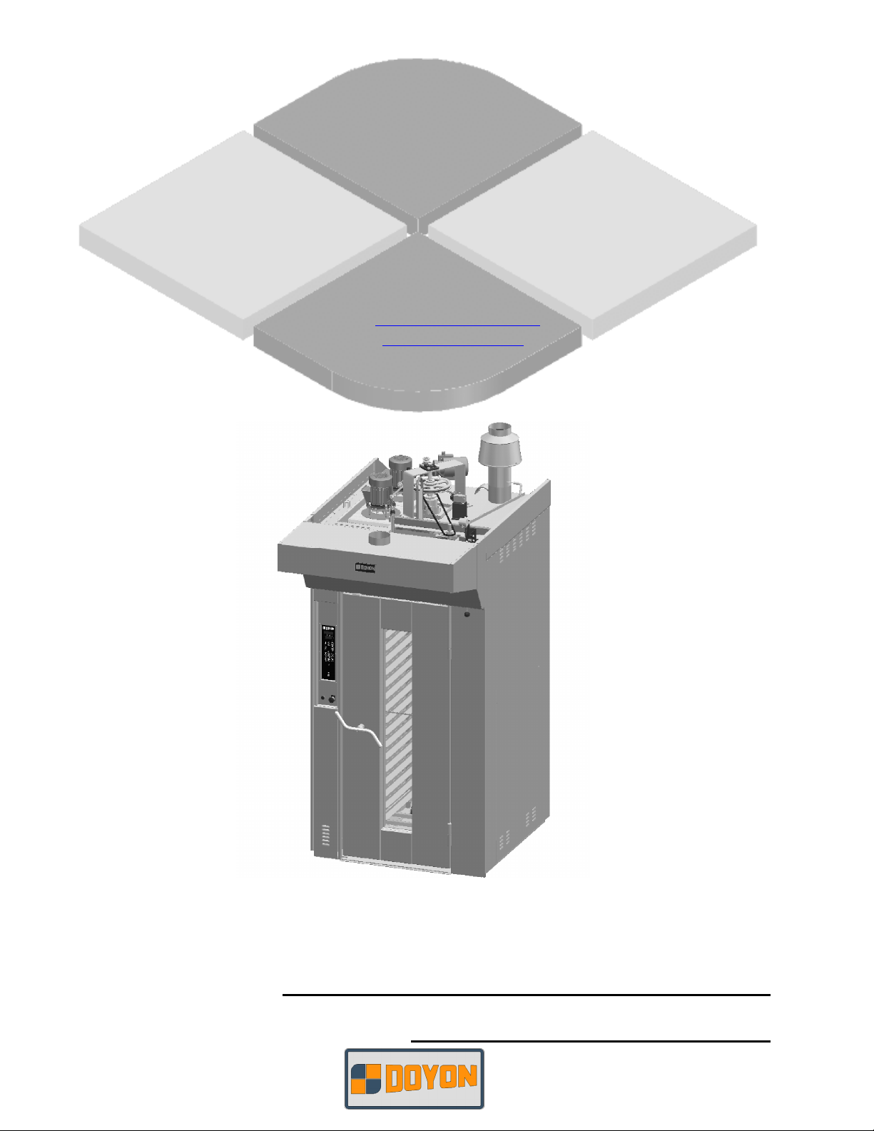
ÉQUIPEMENT DOYON INC.
1255, rue Principale
Linière, Qc, Canada G0M 1J0
Tel.: 1 (418) 685-3431
Canada: 1 (800) 463-1636
US: 1 (800) 463-4273
FAX: 1 (418) 685-3948
Internet: http://www.doyon.qc.ca
e-mail: doyon@doyon.qc.ca
TLOIG - TLOIIG
Product / Produit:
Serial number / Numéro de série:
IMPORTANT SAFETY INSTRUCTIONS
SAVE THESE INSTRUCTIONS
DANGER
TO REDUCE THE RISK OF FIRE OR ELECTRIC SHOCK
CAREFULLY FOLLOW THESE INSTRUCTIONS
TABLE OF CONTENTS
(table des matières :page suivante)
DESCRIPTION________________________________________________________________ A-1
Introduction________________________________________________________________ A-1
Construction _______________________________________________________________ A-1
Shipping __________________________________________________________________ A-1
Installation warnings_________________________________________________________ A-3
Distances to respect__________________________________________________________ A-4
Power failure_______________________________________________________________ A-4
Installation ________________________________________________________________ A-7
ECM-1 Programmable control - Operating modes_________________________________ A-13
Manual mode _____________________________________________________________ A-15
Program mode_____________________________________________________________ A-16
Troubleshooting ___________________________________________________________ A-27
Maintenance and lubrication__________________________________________________ A-31
Oven maintenance and cleaning _______________________________________________ A-31
Maintenance of the burner ___________________________________________________ A-31
Lubrication _______________________________________________________________ A-33
TLO Burner_______________________________________________________________ A-34
Burner setup ______________________________________________________________ A-36
COMPONENT PARTS __________________________________________________________B-1
TLO1G – Front view _________________________________________________________B-1
TLO1G – Top view___________________________________________________________B-3
Rack holder assembly _________________________________________________________B-5
CONTROL PANELS ____________________________________________________________C-1
TLO Break rack panel_________________________________________________________C-1
TLO1 3PH 120/208 120/240V 60Hz _____________________________________________C-2
TLO2 3PH 120/208 120/240V 60Hz _____________________________________________C-3
CAUTION
In case of strong gas odours, shut off the gas input valve and contact a specialised gas
technician
FAM TLOG.doc 06/09

IMPORTANT INSTRUCTIONS DE SÉCURITÉ
CONSERVEZ CE MANUEL D’INSTRUCTIONS
DANGER
AFIN DE RÉDUIRE LES RISQUES D'INCENDIE OU D'ÉLECTROCUTION
SUIVRE CES INSTRUCTIONS AVEC SOIN
TABLE DES MATIÈRES
DESCRIPTION _________________________________________________________________A-2
Introduction ________________________________________________________________A-2
Construction ________________________________________________________________A-2
Expédition __________________________________________________________________A-2
Avertissement lors de l'installation_______________________________________________A-5
Distances à respecter _________________________________________________________A-6
Panne de courant ____________________________________________________________A-6
Installation ________________________________________________________________A-10
Contrôle programmable ECM-1 - Modes d'opération _______________________________A-20
Mode manuel_______________________________________________________________A-22
Mode programmable_________________________________________________________A-23
Dépannage ________________________________________________________________A-29
Entretien et lubrification______________________________________________________A-32
Entretien et nettoyage du four__________________________________________________A-32
Entretien du brûleur _________________________________________________________A-32
Lubrifiaction _______________________________________________________________A-33
Brûleur TLO _______________________________________________________________A-34
Ajustement Brûleur __________________________________________________________A-36
PIÈCES COMPOSANTE _________________________________________________________B-1
TLO1G – Vue de face _________________________________________________________B-1
TLO1G – Vue de dessus _______________________________________________________B-3
Support de chariot ___________________________________________________________B-6
PANNEAUX DE CONTRÔLE _____________________________________________________C-1
TLO Panneau d’arrêt chariot ___________________________________________________C-1
TLO1 3PH 120/208 120/240V 60Hz______________________________________________C-2
TLO2 3PH 120/208 120/240V 60Hz______________________________________________C-3
AVERTISSEMENT
Dans le cas où une odeur de gaz serait détectée, fermer la valve d'admission de gaz principale du
four et contacter la compagnie locale de gaz ou un technicien spécialisé.
FAM TLOG.doc 06/09
A-1
SECTION A:
DESCRIPTION
INTRODUCTION
The manufacturer suggests to read this manual carefully.
This Jet Air oven is manufactured with first quality material by experienced technicians. Proper
installation and maintenance will guarantee a reliable service for years to come.
A nameplate fixed to the front or right side of the oven specifies the model number, type of combustible,
BTU rating, operating pressures, serial number, voltage and amperage.
Drawings and replacement parts numbers are included in this manual. The electrical diagram is affixed in
the control panel at the back of the oven.
ATTENTION
DOYON is not responsible for damages to the property or the equipment caused by
personnel who is not certified by known organisations. The customer is responsible
for finding qualified technicians in gas, electricity and plumbing for the installation
of the oven.
CONSTRUCTION
You just bought the most advanced gas fired oven in the world, "DOYON" technology at its best. This gas
fired oven is manufactured using the highest quality components and material.
The oven gives a perfect uniform baking with its unique Jet Air convection system. The DOYON oven is
designed with parts that are easy to find.
SHIPPING
For your safety, this equipment has been verified by qualified technicians and carefully crated before
shipment. The freight company assumes full responsibility concerning the delivery in good condition of
the equipment in accepting to transport it.
IMPORTANT
RECEPTION OF THE MERCHANDISE
Take care to verify that the received equipment is not damaged before signing the delivery receipt. If a
damage or a lost part is noticed, write it clearly on the receipt. If it is noticed after the carrier has left,
contact immediately the freight company in order that they do their inspection.
We do not assume the responsibility for damages or losses that may occur during transportation.

A-2
DESCRIPTION
INTRODUCTION
Le fabricant suggère de lire attentivement ce manuel et de suivre avec soin les instructions fournies.
Votre four à convection au gaz est fabriqué avec des matériaux de première qualité par des techniciens
d'expérience. Une utilisation normale et un entretien adéquat de l'équipement vous assureront
plusieurs années de bon service.
Une plaque signalétique, située sur le coin avant droit ou le côté droit du four, mentionne le numéro de
modèle, le type de combustible, BTU, le numéro de série, la tension, l'ampérage et les pressions
d'opérations.
Les dessins et les numéros de pièces de rechange sont inclus dans ce manuel. Le plan électrique est
affiché dans la boîte de contrôle à l'arrière du four.
ATTENTION
Équipement Doyon Inc. ne peut être tenu responsable pour les dommages causés à la
propriété ou à l'équipement par du personnel non certifié par des organismes
accrédités. Le client a la responsabilité de retenir les services d'un technicien
spécialisé gaz ou en électricité et d'un plombier qualifié pour l'installation du four.
CONSTRUCTION
Vous avez maintenant en votre possession le four au gaz le plus performant présentement disponible sur le
marché, un four utilisant la technologie "DOYON" à son meilleur. Ce four au gaz est fabriqué avec des
matériaux de première qualité.
Avec son système unique de convection «Jet Air», ce four vous permettra d'obtenir une cuisson uniforme.
Le four Doyon est fabriqué avec des matériaux et pièces composantes facilement disponibles sur le
marché.
EXPÉDITION
Pour votre protection, cet équipement a été vérifié et emballé avec précaution par des techniciens
qualifiés avant son expédition. La compagnie de transport assume la pleine responsabilité concernant
la livraison de cet équipement en bon état en acceptant de le transporter.
IMPORTANT
RÉCEPTION DE LA MARCHANDISE
Avant de signer le reçu de livraison, prenez soin de vérifier dès la réception si l'équipement n'est pas
endommagé. Si un dommage ou une perte est détecté, écrivez-le clairement sur le reçu de livraison ou
votre bon de transport et faites signer le livreur. Si le dommage est remarqué après le départ du
transporteur, contactez immédiatement la compagnie de transport afin de leur permettre de constater
les dommages causés.
Nous ne pouvons assumer la responsabilité pour les dommages ou les pertes qui pourraient survenir
pendant le transport.
A-3
INSTALLATION WARNINGS
The DOYON gas fired ovens are designed to be used with the gas specified on the descriptive
nameplate. Refer to National Fuel Gas Code, ANSI-Z223.1 and CAN/CGA.B149. Refer to last edition
year for XX. Copies of these are available at:
American Gas Association, 1515 Wilson Boulevard, Arlington, Virginia, 22209.
Canadian Gas Association, 55 rue Scarsdale, Don Mills, Ontario, Canada, M3B 2R3.
POWER FAILURE WARNING
WHEN YOU HAVE A POWER FAILURE, SHUT OFF THE OVEN POWER SWITCH TO
PROTECT THE ELECTRONIC COMPONENTS WHEN THE POWER COMES BACK.
FOR YOUR SAFETY
DO NOT STORE OR USE GASOLINE OR OTHER FLAMMABLE VAPORS
AND LIQUIDS IN THE VICINITY OF THIS OR ANY APPLIANCE.
INSTALLATION AND SERVICE
WARNING
IMPROPER INSTALLATION, ADJUSTMENT, ALTERATION, SERVICE OR
MAINTENANCE CAN CAUSE PROPERTY DAMAGE, INJURY OR DEATH.
READ THE INSTALLATION, OPERATING AND MAINTENANCE INSTRUCTIONS
THOROUGHLY BEFORE INSTALLING OR SERVICING THIS EQUIPMENT.
Installation and service must be done by specialised technicians. Contact a certified gas technician,
electrician and plumber for set up.
The oven must be connected to the utility and electrically grounded in conformity to the effective local
regulations. If these are not established, the oven must be connected according to the Canadian
Electrical Code (CSA-C22.1-XX) or National Electrical Code (NFPA 70-XX). Refer to last edition
year for XX. Installation must also allow proper access for service (24 inches each side and back).
The ovens must be installed with proper ventilation like:
• Under a vent hood
• Or an exhaust pipe connected directly to the oven chimney flue using the draft hood provided with
the oven.
A type B gas vent approved for use with gas appliances must be utilised.
Make sure that provision for adequate air supply is provided for the operation of the oven.
CAUTION
Make sure that the adjustments mentioned in the "Installation" section are correctly done prior
to firing the oven or converting to a new gas.
A-4
DISTANCES TO RESPECT
For the installation near flammable products
A) Back and sides of the oven: 0 inch.
B) Top of the oven: a clearance of 24 inches to the ceiling must exist to permit adequate venting of
the exhaust pipe and hot parts and to give a proper access to a technician.
C) Floor: The oven must be installed on a non-combustible floor.
D) you must have at least 18 inches when you evacuate through a hood canopy.
POWER FAILURE
The burner, the electric gas valve and the regulator are all designed to be failed safe. There is no special
action to take in case of electrical power failure.
A-5
AVERTISSEMENT LORS DE L'INSTALLATION
Les unités au gaz "DOYON" sont fabriquées pour être utilisées uniquement avec le type de gaz spécifié
sur la plaque d'identification. Se référer au Code National de Gaz, ANSI-Z223.1 et CAN/CGA.B149.
Référez-vous à l’année de la dernière édition pour XX. Des copies de ces normes sont disponibles
auprès de :
American Gas Association, 1515 Wilson Boulevard, Arlington, Virginia, 22209.
Association Canadienne du Gaz, 55 rue Scarsdale, Don Mills, Ontario, Canada, M3B 2R3.
PANNE ÉLECTRIQUE
LORS D'UNE PANNE ÉLECTRIQUE, FERMER L'INTERRUPTEUR DU FOUR POUR
PROTÉGER LES COMPOSANTES ÉLECTRONIQUES.
POUR VOTRE SÉCURITÉ
NE PAS EMMAGASINER OU UTILISER D'ESSENCE OU AUTRES VAPEURS
ET LIQUIDES INFLAMMABLES À PROXIMITÉ DE CET ÉQUIPEMENT
OU DE TOUT AUTRE APPAREIL.
INSTALLATION ET SERVICE
AVERTISSEMENT
UNE INSTALLATION, UN AJUSTEMENT, UNE ALTÉRATION, UN SERVICE OU UN
ENTRETIEN NON CONFORME AUX NORMES PEUT CAUSER DES DOMMAGES À LA
PROPRIÉTÉ, DES BLESSURES OU LA MORT. LIRE ATTENTIVEMENT LES DIRECTIVES
D'INSTALLATION, D'OPÉRATION ET D'ENTRETIEN AVANT DE FAIRE L'INSTALLATION
OU L'ENTRETIEN DE L'ÉQUIPEMENT.
L'installation et le service doivent être faits par un technicien spécialisé. Contactez un technicien
spécialisé en gaz, en électricité et un plombier certifié pour l'installation.
Cet appareil doit être branché et mis à la terre (grounded) conformément aux règlements effectifs de votre
localité. Si aucune réglementation n'est établie, le four doit être branché conformément au Code
Canadien de l’électricité CSA 22.1-XX ou au Code National de l'Électricité NFPA 70-XX. Référez-vous à
l’année de la dernière édition pour XX. L’installation doit aussi permettre un accès suffisant pour
effectuer le service sur l’équipement (24 pouces sur toutes les faces).
Le four doit être installé sous une ventilation adéquate :
• Soit sous une hotte de ventillation
• Ou un tuyau d’échappement d'échappement doit être branché au-dessus du coupe tirage fourni avec
l'appareil
Le tuyau d'échappement de type B approuvé pour les appareils au gaz doit être utilisé.
Assurez-vous d'avoir un approvisionnement d'air suffisant afin d'assurer une ventilation adéquate pour le
bon fonctionnement du four.
AVERTISSEMENT
Assurez-vous que les ajustements mentionnés dans la section "Installation" ont été faits correctement
avant d'allumer le four ou de le convertir à un autre type de gaz.
A-6
DISTANCES À RESPECTER
Lors de l’installation près de produits inflammables
A) Arrière et côtés du four : 0 pouce.
B) Dessus du four : Il est obligatoire d'avoir au moins 24 pouces entre le dessus du four et le
plafond de manière à permettre une ventilation adéquat du tuyau d’évacuation
et des parties chauffantes tout en permettant l’accès à un technicien.
C) Plancher : Le four doit être installé sur un plancher non combustible.
D) Il doit y avoir au moins 18 pouces lorsque le four est installé sous une hotte ventilée.
PANNE DE COURANT
Le brûleur et la valve à gaz automatique sont conçus de manière à être sécuritaires. La valve ferme en
cas de panne électrique. Il n’y a donc aucune action spéciale à prendre.
A-7
INSTALLATION
Take off the packaging material with care. Take off all the material used for packing and accessories.
Bolt the oven to the floor using the 5 bolts included with the oven. Seal the unit on the floor with
silicone. Install the draft hood on the chimney of the oven. Verify every adjustments and correct it if
necessary. Install the hood covering the top front of the oven.
Each unit is set up to be used with the type of gas and electrical supply specified on the nameplate fixed
on the oven.
The installation must be conform with National fuel gas code ANSI Z223.1-XX and CAN/CGA-B149XX, Gas installation Code and local Codes where applicable. Refer to last edition year for XX.
The oven's combustion system consists of a very safe gas burner certified in accordance to the
American Gas Association Standard in USA and with the Canadian Gas Association in Canada.
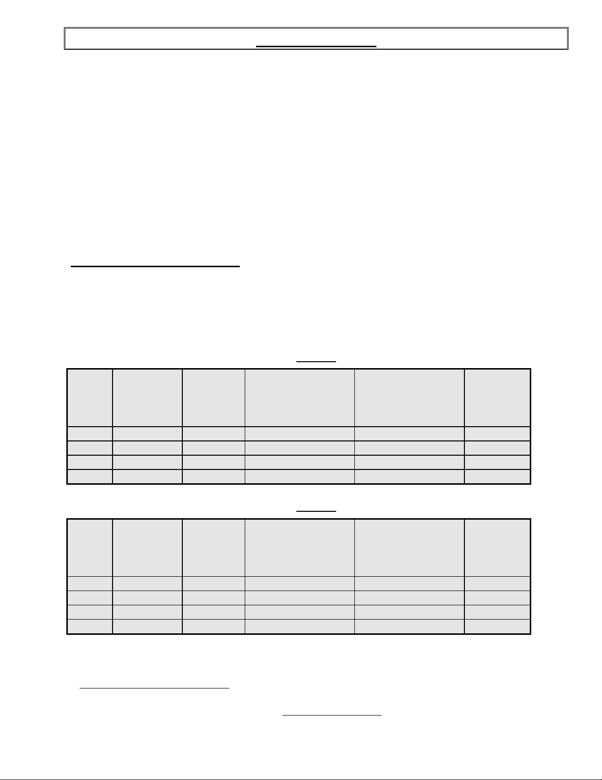
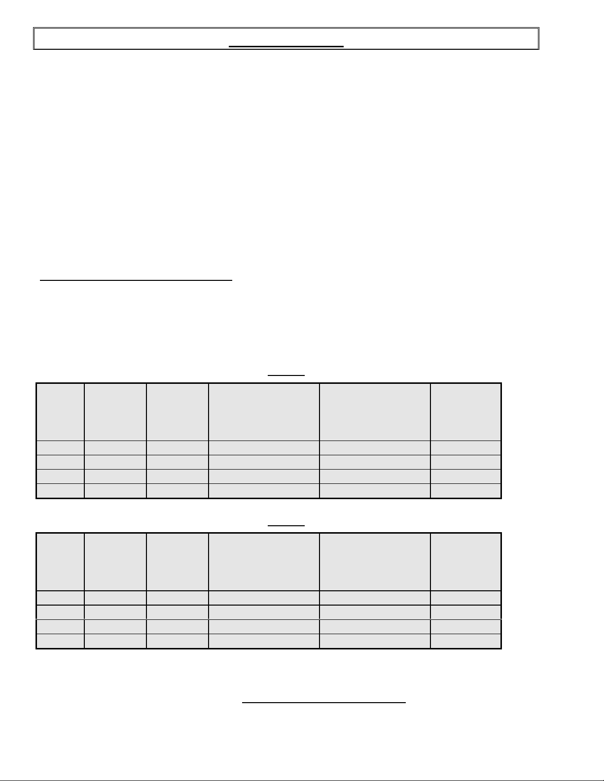
1. To the certified gas technician
The burner installed on DOYON gas fired ovens is set up and adjusted at the plant for a first class
operation. It is nevertheless necessary to verify on site the pressure at the burner input. The
following table indicates the pressures that must be set up to remain conform to the AGA standards
or CGA.
TLO1G
INPUT
GAS
TYPE
ALTITUDE
(FT)
(BTU)
EACH
OVEN
SECTION
REGULATOR
INPUT PRESSURE
(Water column inches)
BURNER INPUT
PRESSURE
(Water column inches)
BURNER
ORIFICE
SIZE (DMS)
Propane 0-2000 200,000 11.0 7.5 # 15 drill
Propane 2000-4500 200,000 11.0 7.5 # 15 drill
Natural 0-2000 200,000 7.0 3.5 19/64
Natural 2000-4500 200,000 7.0 3.5 19/64
TLO2G
INPUT
GAS
TYPE
ALTITUDE
(FT)
(BTU)
EACH
OVEN
SECTION
REGULATOR
INPUT PRESSURE
(Water column inches)
BURNER INPUT
PRESSURE
(Water column inches)
BURNER
ORIFICE
SIZE (DMS)
Propane 0-2000 300,000 11.0 7.5 7/32
Propane 2000-4500 300,000 11.0 7.5 7/32
Natural 0-2000 300,000 7.0 3.5 23/64
Natural 2000-4500 300,000 7.0 3.5 23/64
The burner used is adjusted for use with the gas indicated on the nameplate. It is nevertheless
possible to convert the burner to another gas by doing the modifications indicated in the
CONVERSION PROCEDURE provided with the oven. These modifications must be done carefully
and completely under the company's instruction to remain conform to A.G.A. or C.G.A standards.
Refer to Doyon Equipment to get the right CONVERSION KIT.

A-8
The installation must be made with a connector that meets with the standard for connectors
movable gas appliances ANSI Z21.69-XX and a Quick-disconnect device that complies with the
standard for Quick-disconnect devices for use with gas fuel ANSI Z21.41-XX and addenda
Z21.41a-XX and Z21.41b-XX. Refer to last edition year for XX. It must also be installed with
restraining device (chain comes with the oven) to guard against transmission of strain to the gas
supply and connectors. The pipe fittings compound must be certified for gas.
The customer must install a manual shut off valve at the end of the gas supply pipe near the burner
which is approved by the American Gas Association Standard in the United States and with the
Canadian Gas Association in Canada.
Exhaust: A draft hood is provided with the unit and it must be used when the chimney is directly
connected to a gas vent pipe. The exhaust pipe must be certified for use of gases.
Clean the air contained in the gas supply pipe at the installation to insure a successful firing on the
first try. The gas pipe sealing compound tightness must be verified using a solution of water and
soap prior to firing the unit.
WARNING
Make sure not to obstruct the overpressure opening on the gas regulator.
NOTE: If there's any modification done to the system or change of the type of gas used, make
sure that the regulator pressure of the burner is adjusted as recommended in this manual.
2. To the electrician
Electrical supply installation must be in accordance with the electrical rating on the nameplate.
A phase sequence and loss of phase relay is installed on 3 phases models to avoid wrong rotation
direction of the blowers. If the oven does not light up, swap two phases conductors in the supply
box and try again. Be sure that the power is really on the 3 phases wires next to the fuses in the
control compartment on the front of the oven. Check also if the control fuse located near the main
switch is not blown.
WARNING
The electrician must make sure that the supply cable does not come in contact with the
oven top which becomes hot.
3. To the plumber
This equipment is to be installed to comply with the applicable federal, state or local plumbing
codes.
¾ Connect the water supply pipe to the oven using good quality sealing compound. Take care that
combustible water pipes do not come in contact with hot parts on the top of the oven.
¾ Check for leaks of solenoid valve
¾ Connect the steam system (1/4 NPT) to the cold water distribution network.
¾ We highly recommend a water softener to eliminate minerals in the water. We suggest you to use
CUNO # CFS6135 (Doyon part number PLF240).
A-9
WARNING
Do not adjust the needle valves, it has been done at the factory.
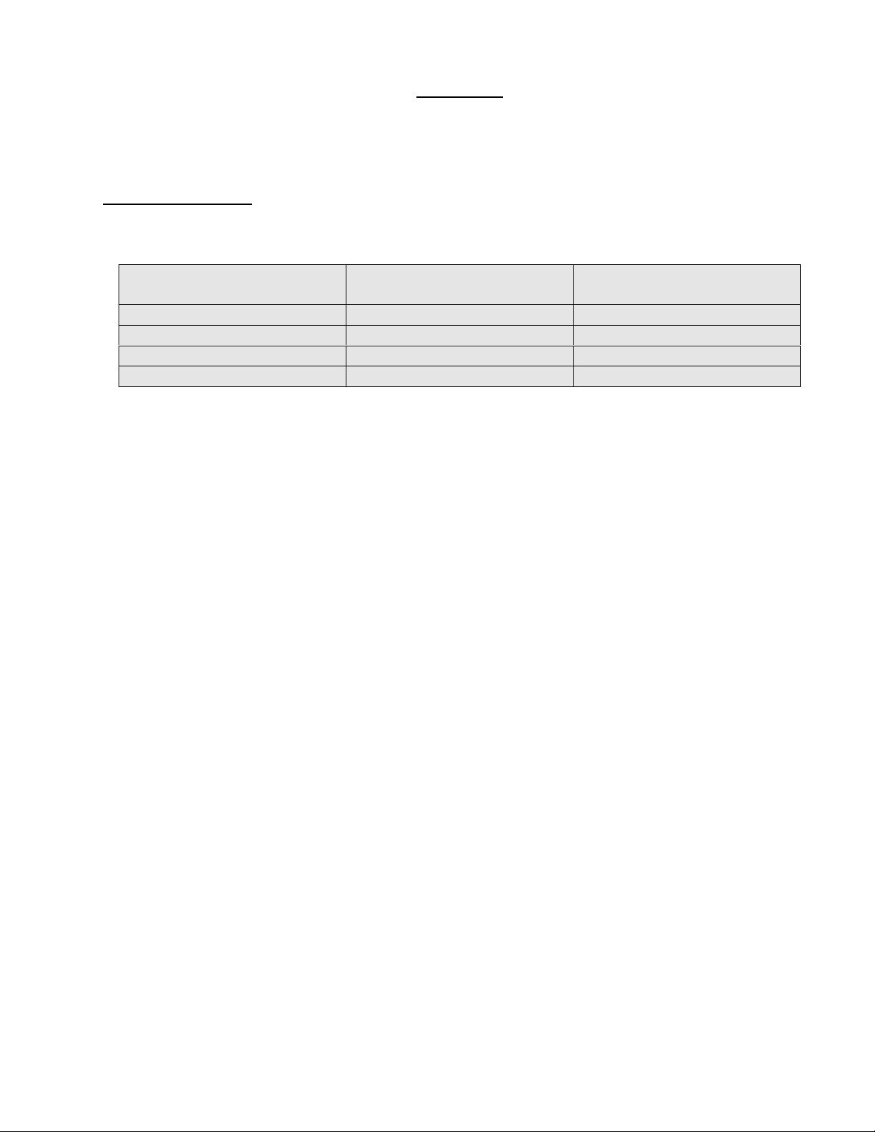
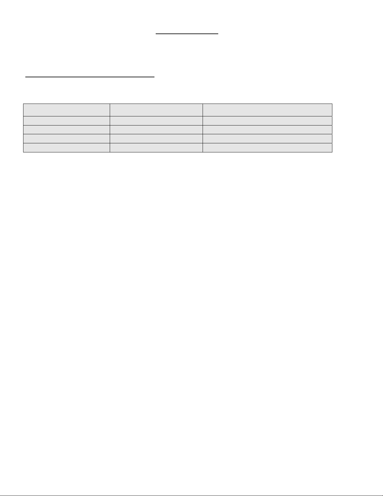
4. Air input settings
Adjust the air trap on the burner blower input as stated below:
OVEN GAS TYPE AIR ADJUSTEMENT
TLOIG Propane 6.75
TLOIG Natural 5.5
TLOIIG Propane 4
TLOIIG Natural 3.5
A-10
INSTALLATION
Ouvrir avec soin l'emballage de votre équipement. Enlever tous les matériaux utilisés pour l'envelopper
ainsi que les accessoires. Installer le coupe tirage sur la cheminée du four. Visser le four en utilisant
les cinq (5) boulons inclus avec l’unité. Appliquez un joint de silicone à la base de l’unité. Vérifiez les
ajustements et corrigez au besoin. Installez la hotte recouvrant le brûleur sur le devant du four.
Chaque unité est fabriquée pour être utilisée avec le type de gaz et la source électrique spécifiés sur la
plaque signalétique de l’appareil.
L'installation doit être conforme avec le Code National de Gaz, ANSI-Z223.1-XX et CAN/CGA-B149XX, le code d'installation au gaz et les codes locaux si applicables. Référez-vous à l’année de la
dernière édition pour XX.
Le système de combustion du four est conçu à partir d'un brûleur certifié en conformité avec les normes
de l'Association Américaine des Standards de Gaz et l'Association Canadienne de Gaz.
1. Au technicien spécialisé pour le gaz
Le brûleur installé sur les fours au gaz DOYON est monté et ajusté à l'usine par le fabricant pour
un fonctionnement optimal. Il est néanmoins nécessaire de vérifier sur place la pression à l'entrée
du brûleur. La table suivante indique la pression qui doit être ajustée pour se conformer aux
standards de AGA ou de CGA.
TLO1G
TYPE
DE GAZ
ALTITUDE
(PI)
ENTRÉE
(BTU)
PAR
SECTION
DE FOUR
PRESSION À
L’ENTRÉE DU
RÉGULATEUR
(Colonne d'eau en pouces)
PRESSION À
L'ENTRÉE DU
BRÛLEUR
(Colonne d'eau en pouces)
DIMENSIONS
DE
L'ORIFICE
DU BRÛLEUR
Propane 0-2000 200,000 11.0 7.5 #15 DRILL
Propane 2000-4500 200,000 11.0 7.5 #15 DRILL
Naturel 0-2000 200,000 7.0 3.5 19/64
Naturel 2000-4500 200,000 7.0 3.5 19/64
TLO2G
TYPE
DE GAZ
ALTITUDE
(PI)
ENTRÉE
(BTU)
PAR
SECTION
DE FOUR
PRESSION À
L’ENTRÉE DU
RÉGULATEUR
(Colonne d'eau en pouces)
PRESSION À
L'ENTRÉE DU
BRÛLEUR
(Colonne d'eau en pouces)
DIMENSIONS
DE
L'ORIFICE
DU BRÛLEUR
Propane 0-2000 300,000 11.0 7.5 7/32
Propane 2000-4500 300,000 11.0 7.5 7/32
Naturel 0-2000 300,000 7.0 3.5 23/64
Naturel 2000-4500 300,000 7.0 3.5 23/64
Le brûleur utilisé est ajusté pour être installé seulement avec le type de gaz spécifié sur la plaque
d'identification. Il est néanmoins possible de convertir le brûleur à un autre type de gaz en suivant
les modifications mentionnées dans la PROCÉDURE DE CONVERSION fournis avec le four. Pour
demeurer conforme aux standards de AGA et CGA, ces modifications doivent être faites au complet
et avec précaution en suivant les instructions du manufacturier. Se référer à Équipement Doyon
pour obtenir le nécessaire de conversion adéquat.

A-11
L'installation doit être faite avec un connecteur conforme aux standards des unités de gaz
amovibles ANSI-Z21.69-XX et un appareil "Quick-Disconnect" conforme aux standards pour les
appareils "Quick-Disconnect" pour utilisation avec du gaz ANSIZ1.41-XX et addenda Z21.41a-XX
et Z21-41b-XX. Référez-vous à l’année de la dernière édition pour XX. De plus, des équipements de
retenues (chaîne comprise avec le four) doivent être installés pour empêcher le tuyau
d'alimentation et les connecteurs de subir des tensions lorsque le four est déplacé. Le composé de
joint à tuyau utilisé pour relier les appareils au gaz doit être certifié résistant à l'action du gaz.
Le client doit installer une vanne manuelle à la sortie de l'alimentation au gaz près du brûleur,
laquelle doit être approuvée par l'Association Américaine des Standards de Gaz aux États-Unis et
par l'Association Canadienne de Gaz au Canada.
Échappement: Un coupe tirage est expédié avec chaque four. Il doit être utilisé lorsque le four
est branché directement à une cheminée. Le tuyau de sortie doit être certifié au
gaz.
Pour vous assurer d'un bon allumage lors de votre premier essai, videz le tuyau d'alimentation au
gaz de l'air qu'il contient lors de l'installation. Les joints des tuyaux devraient être vérifiés avec
une solution d'eau et de savon pour détecter les fuites avant de faire fonctionner l'unité.
ATTENTION
Ne pas obstruer le limiteur de fuite du régulateur de pression.
NOTE: Dans le cas d'une modification du système ou d'un changement de type de gaz, s'assurer
d'ajuster la pression du régulateur du brûleur telle que recommandée dans ce manuel.
2. À l'électricien
L'installation de l'alimentation électrique des fours doit être conforme avec la source électrique
spécifiée sur la plaque signalétique.
AVERTISSEMENT
L'électricien doit s'assurer que le câble d'alimentation ne touche pas le dessus du four à
cause du degré élevé de chaleur dégagé par celui-ci.
Un relai de détection d’ordre de phases et de perte de phase est installé sur le modèle 3 phases afin
d’éviter une rotation en sens inverse des ventilateurs. Si le four ne réagit pas lors de la mise en
marche, inverser deux phases et réessayer. Assurez-vous que la tension apparaît bien sur les trois
conducteurs de phase à la sortie des fusibles d’entrées situées dans le compartiment de contrôle sur
le devant du four. Vérifiez aussi que le fusible du circuit de contrôle situé près des boutons n’est
pas brûlé.
3. Au plombier
¾ Faire le raccordement d’entrée d’eau au four en utilisant des matériaux de qualité assurant
l’étanchéité. S’assurer que le tuyau d’arrivée d’eau n’est pas en contact avec les parties chaudes
sur le dessus du four.
¾ Vérifier l’étanchéité de la valve électrique.
¾ Relier le système de vapeur (1/4 NPT) au réseau de distribution d'eau froide.
¾ Il est fortement recommandé d’installer un adoucisseur d’eau à l’entrée de l’appareil afin
d’éliminer les minéraux dans l’eau.
¾ Nous recommandons la marque CUNO # CFS6135 (numéro de pièce DOYON PLF240).
AVERTISSEMENT
Ne jamais changer l'ajustement des valves à aiguille pré-ajustées.
4. Ajustement de l’entrée d’air du brûleur
Ajuster la position de la trappe d’entrée d’air du brûleur aux positions suivantes :
FOUR TYPE DE GAZ AJUSTEMENT D’AIR
TLOIG Propane 6.75
TLOIG Naturel 5.5
TLOIIG Propane 4
TLOIIG Naturel 3.5
A-12
A-13
ECM-1 PROGRAMMABLE CONTROL - OPERATING MODES
The Doyon ECM-1 controller has two operation modes Manual and Programmable.
MANUAL: to use all functions without using recipe program.
PROGRAMMABLE: to use with recipe cook program.
Program capacity
□ Programs #1 to #99 can have up to 10 steps each (low-level programmable).
□ Program #0 is always used as the default Manual Cook mode setting (single-step).
OFF MODE
Display/LED
□ Display shows OFF.
□ All other LEDs are off, except the
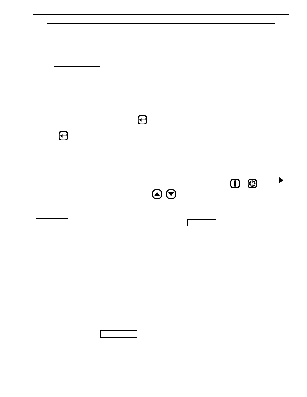
Press on (start) when the oven is ON, the oven will run on preheat mode at the manual mode set
point (except if you select a cook program referred in How to Select a Cook Program or the Manual
Mode section).
To switch the oven OFF Press the RED stop button and hold it for 3 seconds. The oven will run on
cool down mode until it reaches 250°F and then switch OFF.
To change the temperature set point or timer setting press and hold for 3 sec. on
appears on the left side of the display, press on / (up / down) to select the desired temperature
set point or timer setting. The new set point or time setting will be automatically saved after 3 seconds.
Display/LED
□ Display scrolls current cook program name (by default MANUAL if no program yet selected).
□ 2nd line shows actual oven temperature.
□ Heat and Fan, LED follows output state.
□ Ready LED blinks.
□ Stop LED is on.
This is the default mode when the controller powers up.
Start key LED.
or
. When
When probe temperature reaches set point, the unit beeps 5 seconds, the ready LED stays on and the
oven goes into COOK MODE.
When the oven is ON, a 3 second long press of red Stop key will go to Cool Down mode if the oven
temperature is over 250°F / 120°C before going to OFF mode. If the temperature is bellow 250°F /
120°C, the oven goes directly to the OFF mode.
DOOR SWITCH
□ If door is opened:
○ Display scrolls DOOR OPEN.
○ All outputs are turned off (unless in Cool Down mode, then fan remains on).
○ All timers pause until the door is closed.
□ When the door is closed, a short delay must expire before all accessories resume normal
operation.
 Loading...