


ÉQUIPEMENT DOYON INC.
1255, rue Principale Linière, Qc, Canada G0M 1J0
Tel.: 1 (418) 685-3431
Canada: 1 (800) 463-1636
US: 1 (800) 463-4273
FAX: 1 (418) 685-3948
Internet: http://www.doyon.qc.ca e-mail: doyon@doyon.qc.ca
JA6SLG - JA6SLSCG - JAOP6SLG - JA12SLG - JAOP12SLG
Product / Produit:
Serial number / Numéro de série:

IMPORTANT SAFETY INSTRUCTIONS
SAVE THESE INSTRUCTIONS
DANGER
TO REDUCE THE RISK OF FIRE OR ELECTRIC SHOCK
CAREFULLY FOLLOW THESE INSTRUCTIONS
TABLE OF CONTENTS
(table des matières :page suivante)
DESCRIPTION________________________________________________________________ A-1 Introduction________________________________________________________________ A-1 Construction _______________________________________________________________ A-1 Shipping __________________________________________________________________ A-1 Installation warnings_________________________________________________________ A-3 Distances to respect__________________________________________________________ A-4 Installation ________________________________________________________________ A-7 Operation of the oven _______________________________________________________ A-11 Instructions for oven ________________________________________________________ A-13 Operation of the proofer _____________________________________________________ A-15 Power failure______________________________________________________________ A-15 ECM-1 Programmable control - Operating modes_________________________________ A-17 Manual mode _____________________________________________________________ A-19 Program mode_____________________________________________________________ A-20 ECM-2 Programmable control - Operating modes_________________________________ A-31 Troubleshooting ___________________________________________________________ A-33 Oven maintenance and cleaning _______________________________________________ A-37 Bake chart ________________________________________________________________ A-39
COMPONENT PARTS __________________________________________________________B-1 JAOP12SLG – Front view _____________________________________________________B-1 JAOP12SLG – Right side view _________________________________________________B-3 JAOP12SLG – Left side view___________________________________________________B-5 JAOP12SLG – Back view _____________________________________________________B-7
CONTROL PANELS ____________________________________________________________C-1 1PH 120V with Zelio _________________________________________________________C-1 1PH 120V without Zelio_______________________________________________________C-2 120/208-240V 1PH with Zelio simple ____________________________________________C-3 120/208-240V without Zelio simple______________________________________________C-4
BURNER ADJUSTEMENTS ____________________________________________________ D-1 Natural gas ________________________________________________________________ D-1 Propane gas ________________________________________________________________ D-2
CAUTION
In case of strong gas odours, shut off the gas input valve and contact a specialised gas technician
FAMSLG [LIVRET].doc |
04/10 |

IMPORTANT INSTRUCTIONS DE SÉCURITÉ
CONSERVEZ CE MANUEL D’INSTRUCTIONS
DANGER
AFIN DE RÉDUIRE LES RISQUES D'INCENDIE OU D'ÉLECTROCUTION
SUIVRE CES INSTRUCTIONS AVEC SOIN
TABLE DES MATIÈRES
DESCRIPTION _________________________________________________________________A-2 Introduction ________________________________________________________________A-2 Construction ________________________________________________________________A-2 Expédition __________________________________________________________________A-2 Avertissement lors de l'installation_______________________________________________A-5 Distances à respecter _________________________________________________________A-6 Installation _________________________________________________________________A-9 Opération du four ___________________________________________________________A-12 Instructions pour four ________________________________________________________A-14 Opération de l'étuve _________________________________________________________A-16 Panne de courant ___________________________________________________________A-16 Contrôle programmable ECM-1 - Modes d'opération _______________________________A-24 Mode manuel_______________________________________________________________A-26 Mode programmable_________________________________________________________A-27 Contrôle programmable ECM-2 - Modes d'opération _______________________________A-32 Dépannage ________________________________________________________________A-35 Entretien et nettoyage du four__________________________________________________A-38 Tableau de cuisson __________________________________________________________A-40
PIÈCES COMPOSANTE _________________________________________________________B-1 JAOP12SLG – Vue de face _____________________________________________________B-1 JAOP12SLG – Vue de côté droit ________________________________________________B-3 JAOP12SLG – Vue de côté gauche_______________________________________________B-5 JAOP12SLG – Vue arrière _____________________________________________________B-7
PANNEAUX DE CONTRÔLE _____________________________________________________C-1 1PH 120V avec Zelio _________________________________________________________C-1 1PH 120V sans Zelio _________________________________________________________C-2 120/208-240V avec Zelio simple_________________________________________________C-3 120/208-240V sans Zelio simple_________________________________________________C-4
AJUSTEMENT DU BRÛLEUR____________________________________________________ D-1 Gaz naturel ________________________________________________________________ D-1 Gaz propane _______________________________________________________________ D-2
AVERTISSEMENT
Dans le cas où une odeur de gaz serait détectée, fermer la valve d'admission de gaz principale du four et contacter la compagnie locale de gaz ou un technicien spécialisé.

A-1
SECTION A:
DESCRIPTION
INTRODUCTION
The manufacturer suggests to read this manual carefully.
This Jet Air oven is manufactured with first quality material by experienced technicians. Proper installation and maintenance will guarantee a reliable service for years to come.
A nameplate fixed to the front or right side of the oven specifies the model number, type of combustible, BTU rating, operating pressures, serial number, voltage and amperage.
Drawings and replacement parts numbers are included in this manual. The electrical diagram is affixed in the control panel at the back of the oven.
ATTENTION
DOYON is not responsible for damages to the property or the equipment caused by personnel who is not certified by known organisations. The customer is responsible for finding qualified technicians in gas, electricity and plumbing for the installation of the oven.
CONSTRUCTION
You just bought the most advanced gas fired oven in the world, "DOYON" technology at its best. This gas fired oven is manufactured using the highest quality components and material.
The oven gives a perfect uniform baking with its unique Jet Air convection system. The DOYON oven is designed with parts that are easy to find.
SHIPPING
For your safety, this equipment has been verified by qualified technicians and carefully crated before shipment. The freight company assumes full responsibility concerning the delivery in good condition of the equipment in accepting to transport it.
IMPORTANT
RECEPTION OF THE MERCHANDISE
Take care to verify that the received equipment is not damaged before signing the delivery receipt. If a damage or a lost part is noticed, write it clearly on the receipt. If it is noticed after the carrier has left, contact immediately the freight company in order that they do their inspection.
We do not assume the responsibility for damages or losses that may occur during transportation.
A-2
DESCRIPTION
INTRODUCTION
Le fabricant suggère de lire attentivement ce manuel et de suivre avec soin les instructions fournies.
Votre four à convection au gaz est fabriqué avec des matériaux de première qualité par des techniciens d'expérience. Une utilisation normale et un entretien adéquat de l'équipement vous assureront plusieurs années de bon service.
Une plaque signalétique, située sur le coin avant droit ou le côté droit du four, mentionne le numéro de modèle, le type de combustible, BTU, le numéro de série, la tension, l'ampérage et les pressions d'opérations.
Les dessins et les numéros de pièces de rechange sont inclus dans ce manuel. Le plan électrique est affiché dans la boîte de contrôle à l'arrière du four.
ATTENTION
Équipement Doyon Inc. ne peut être tenu responsable pour les dommages causés à la propriété ou à l'équipement par du personnel non certifié par des organismes accrédités. Le client a la responsabilité de retenir les services d'un technicien spécialisé gaz ou en électricité et d'un plombier qualifié pour l'installation du four.
CONSTRUCTION
Vous avez maintenant en votre possession le four au gaz le plus performant présentement disponible sur le marché, un four utilisant la technologie "DOYON" à son meilleur. Ce four au gaz est fabriqué avec des matériaux de première qualité.
Avec son système unique de convection «Jet Air», ce four vous permettra d'obtenir une cuisson uniforme. Le four Doyon est fabriqué avec des matériaux et pièces composantes facilement disponibles sur le marché.
EXPÉDITION
Pour votre protection, cet équipement a été vérifié et emballé avec précaution par des techniciens qualifiés avant son expédition. La compagnie de transport assume la pleine responsabilité concernant la livraison de cet équipement en bon état en acceptant de le transporter.
IMPORTANT
RÉCEPTION DE LA MARCHANDISE
Avant de signer le reçu de livraison, prenez soin de vérifier dès la réception si l'équipement n'est pas endommagé. Si un dommage ou une perte est détecté, écrivez-le clairement sur le reçu de livraison ou votre bon de transport et faites signer le livreur. Si le dommage est remarqué après le départ du transporteur, contactez immédiatement la compagnie de transport afin de leur permettre de constater les dommages causés.
Nous ne pouvons assumer la responsabilité pour les dommages ou les pertes qui pourraient survenir pendant le transport.

A-3
INSTALLATION WARNINGS
The DOYON gas fired ovens are designed to be used with the gas specified on the descriptive nameplate. Refer to National Fuel Gas Code, ANSI-Z223.1 and CAN/CGA.B149. Refer to last edition year for XX. Copies of these are available at:
American Gas Association, 1515 Wilson Boulevard, Arlington, Virginia, 22209. Canadian Gas Association, 55 rue Scarsdale, Don Mills, Ontario, Canada, M3B 2R3.
POWER FAILURE WARNING
WHEN YOU HAVE A POWER FAILURE, SHUT OFF THE OVEN POWER SWITCH TO PROTECT THE ELECTRONIC COMPONENTS WHEN THE POWER COMES BACK.
FOR YOUR SAFETY
DO NOT STORE OR USE GASOLINE OR OTHER FLAMMABLE VAPORS AND LIQUIDS IN THE VICINITY OF THIS OR ANY APPLIANCE.
INSTALLATION AND SERVICE
WARNING
IMPROPER INSTALLATION, ADJUSTMENT, ALTERATION, SERVICE OR MAINTENANCE CAN CAUSE PROPERTY DAMAGE, INJURY OR DEATH.
READ THE INSTALLATION, OPERATING AND MAINTENANCE INSTRUCTIONS THOROUGHLY BEFORE INSTALLING OR SERVICING THIS EQUIPMENT.
Installation and service must be done by specialised technicians. Contact a certified gas technician, electrician and plumber for set up.
The oven must be connected to the utility and electrically grounded in conformity to the effective local regulations. If these are not established, the oven must be connected according to the Canadian Electrical Code (CSA-C22.1-XX) or National Electrical Code (NFPA 70-XX). Refer to last edition year for XX. Installation must also allow proper access for service (24 inches each side and back).
The ovens must be installed with proper ventilation like:
•Under a vent hood
•Or an exhaust pipe connected directly to the oven chimney flue using the draft hood provided with the oven.
A type B gas vent approved for use with gas appliances must be utilised.
Make sure that provision for adequate air supply is provided for the operation of the oven.
CAUTION
Make sure that the adjustments mentioned in the "Installation" section are correctly done prior to firing the oven or converting to a new gas.

A-4
DISTANCES TO RESPECT
A)Back and sides of the oven: 1 inch.
B)Top of the oven: a clearance of 12 inches to the ceiling must exist to permit adequate venting
of the exhaust pipe and hot parts and to give proper access to a technician. The draft hood must have a clearance of 2 inches minimum all around.
C)Floor: 4 inches minimum.
D)Sides of the oven: do not install other than easily removable equipment for service and
maintenance (not closer than 1 inch).
E)It is recommended to have a certain length of water pipe, electric cable and gas pipe between oven and wall to help gain access for service.

A-5
AVERTISSEMENT LORS DE L'INSTALLATION
Les unités au gaz "DOYON" sont fabriquées pour être utilisées uniquement avec le type de gaz spécifié sur la plaque d'identification. Se référer au Code National de Gaz, ANSI-Z223.1 et CAN/CGA.B149. Référez-vous à l’année de la dernière édition pour XX. Des copies de ces normes sont disponibles auprès de :
American Gas Association, 1515 Wilson Boulevard, Arlington, Virginia, 22209. Association Canadienne du Gaz, 55 rue Scarsdale, Don Mills, Ontario, Canada, M3B 2R3.
PANNE ÉLECTRIQUE
LORS D'UNE PANNE ÉLECTRIQUE, FERMER L'INTERRUPTEUR DU FOUR POUR
PROTÉGER LES COMPOSANTES ÉLECTRONIQUES.
POUR VOTRE SÉCURITÉ
NE PAS EMMAGASINER OU UTILISER D'ESSENCE OU AUTRES VAPEURS ET LIQUIDES INFLAMMABLES À PROXIMITÉ DE CET ÉQUIPEMENT OU DE TOUT AUTRE APPAREIL.
INSTALLATION ET SERVICE
AVERTISSEMENT
UNE INSTALLATION, UN AJUSTEMENT, UNE ALTÉRATION, UN SERVICE OU UN ENTRETIEN NON CONFORME AUX NORMES PEUT CAUSER DES DOMMAGES À LA PROPRIÉTÉ, DES BLESSURES OU LA MORT. LIRE ATTENTIVEMENT LES DIRECTIVES D'INSTALLATION, D'OPÉRATION ET D'ENTRETIEN AVANT DE FAIRE L'INSTALLATION OU L'ENTRETIEN DE L'ÉQUIPEMENT.
L'installation et le service doivent être faits par un technicien spécialisé. Contactez un technicien spécialisé en gaz, en électricité et un plombier certifié pour l'installation.
Cet appareil doit être branché et mis à la terre (grounded) conformément aux règlements effectifs de votre localité. Si aucune réglementation n'est établie, le four doit être branché conformément au Code Canadien de l’électricité CSA 22.1-XX ou au Code National de l'Électricité NFPA 70-XX. Référez-vous à l’année de la dernière édition pour XX. L’installation doit aussi permettre un accès suffisant pour effectuer le service sur l’équipement (24 pouces sur toutes les faces).
Le four doit être installé sous une ventilation adéquate :
•Soit sous une hotte de ventillation
•Ou un tuyau d’échappement d'échappement doit être branché au-dessus du coupe tirage fourni avec l'appareil
Le tuyau d'échappement de type B approuvé pour les appareils au gaz doit être utilisé.
Assurez-vous d'avoir un approvisionnement d'air suffisant afin d'assurer une ventilation adéquate pour le bon fonctionnement du four.
AVERTISSEMENT
Assurez-vous que les ajustements mentionnés dans la section "Installation" ont été faits correctement avant d'allumer le four ou de le convertir à un autre type de gaz.

A-6
DISTANCES À RESPECTER
A)Arrière et côtés du four : 1 pouce.
B)Dessus du four : Il est obligatoire d'avoir au moins 12 pouces entre le dessus du four et le
plafond de manière à permettre une ventilation adéquate du tuyau d'évacuation et des parties chauffantes tout en permettant l'accès à un technicien. Il faut avoir au moins 2 pouces de dégagement tout autour du coupe tirage.
C)Plancher : Une distance de 4 pouces minimum.
D)Les côtés du four : Installer uniquement des équipements légers et faciles à déplacer pour être en
mesure d'effectuer l'entretien de l'appareil (1 pouce minimum).
E)Il est recommandé d'installer une longueur supplémentaire de tuyau d'eau, de câble électrique et de conduite de gaz entre le four et le mur pour faciliter l'accès au technicien.

A-7
INSTALLATION
IN GENERAL
Take off the packaging material with care. Take off all the material used for packing and accessories. Install the draft hood on the chimney of the oven.
Each unit is set up to be used with the type of gas and electrical supply specified on the nameplate fixed on the oven.
The installation must be conform with National fuel gas code ANSI Z223.1-XX and CAN/CGA- B149-XX, Gas installation Code and local Codes where applicable. Refer to last edition year for XX.
The oven's combustion system consists of a very safe gas burner certified in accordance to the American Gas Association Standard in USA and with the Canadian Gas Association in Canada.
1. To the certified gas technician
The burner installed on DOYON gas fired ovens is set up and adjusted at the plant for a first class operation. It is nevertheless necessary to verify on site the pressure at the burner input. The following table indicates the pressures that must be set up to remain conform to the AGA standards or CGA.
|
|
INPUT |
REGULATOR |
BURNER INPUT |
BURNER |
|
GAS |
ALTITUDE |
(BTU) |
||||
EACH |
INPUT PRESSURE |
PRESSURE |
ORIFICE |
|||
TYPE |
(FT) |
|||||
OVEN |
(Water column inches) |
(Water column inches) |
SIZE (DMS) |
|||
|
|
|||||
|
|
SECTION |
|
|
|
|
Propane |
0-2000 |
65,000 |
11.0 |
7.0 |
39 |
|
Propane |
2000-4500 |
65,000 |
11.0 |
7.0 |
39 |
|
Natural |
0-2000 |
65,000 |
7.0 |
3.3 |
26 |
|
Natural |
2000-4500 |
65,000 |
7.0 |
3.3 |
26 |
The burner used is adjusted for use with the gas indicated on the nameplate. It is nevertheless possible to convert the burner to another gas by doing the modifications indicated in the CONVERSION PROCEDURE provided with the oven. These modifications must be done carefully and completely under the company's instruction to remain conform to A.G.A. or C.G.A standards. Refer to Doyon Equipment to get the right CONVERSION KIT.
The installation must be made with a connector that meets with the standard for connectors movable gas appliances ANSI Z21.69-XX and a Quick-disconnect device that complies with the standard for Quick-disconnect devices for use with gas fuel ANSI Z21.41-XX and addenda Z21.41a-XX and Z21.41b-XX. Refer to last edition year for XX. It must also be installed with restraining device (chain comes with the oven) to guard against transmission of strain to the gas supply and connectors. The pipe fittings compound must be certified for gas.
A-8
The customer must install a manual shut off valve at the end of the gas supply pipe near the burner which is approved by the American Gas Association Standard in the United States and with the Canadian Gas Association in Canada.
Exhaust: A draft hood is provided with the unit and it must be used when the chimney is directly connected to a gas vent pipe. The exhaust pipe must be certified for use of gases.
Clean the air contained in the gas supply pipe at the installation to insure a successful firing on the first try. The gas pipe sealing compound tightness must be verified using a solution of water and soap prior to firing the unit.
WARNING
Make sure not to obstruct the overpressure opening on the gas regulator.
NOTE: If there's any modification done to the system or change of the type of gas used, make sure that the regulator pressure of the burner is adjusted as recommended in this manual.
2. To the electrician
Electrical supply installation must be in accordance with the electrical rating on the nameplate.
WARNING
The electrician must make sure that the supply cable does not come in contact with the oven top which becomes hot.
3. To the plumber
This equipment is to be installed to comply with the applicable federal, state or local plumbing codes.
Connect the steam system (1/4 NPT) to the cold water distribution network.
We highly recommend a water softener to eliminate minerals in the water. We suggest you to use CUNO # CFS6135 (Doyon part number PLF240).
WARNING
Do not adjust the needle valves, it has been done at the factory.

A-9
INSTALLATION
EN GÉNÉRAL
Ouvrir avec soin l'emballage de votre équipement. Enlever tous les matériaux utilisés pour l'envelopper ainsi que les accessoires. Installer le coupe tirage sur la cheminée du four.
Chaque unité est fabriquée pour être utilisée avec le type de gaz et la source électrique spécifiés sur la plaque signalétique de l’appareil.
L'installation doit être conforme avec le Code National de Gaz, ANSI-Z223.1-XX et CAN/CGA-B149- XX, le code d'installation au gaz et les codes locaux si applicables. Référez-vous à l’année de la dernière édition pour XX.
Le système de combustion du four est conçu à partir d'un brûleur certifié en conformité avec les normes de l'Association Américaine des Standards de Gaz et l'Association Canadienne de Gaz.
1. Au technicien spécialisé pour le gaz
Le brûleur installé sur les fours au gaz DOYON est monté et ajusté à l'usine par le fabricant pour un fonctionnement optimal. Il est néanmoins nécessaire de vérifier sur place la pression à l'entrée du brûleur. La table suivante indique la pression qui doit être ajustée pour se conformer aux standards de AGA ou de CGA.
|
|
ENTRÉE |
PRESSION À |
PRESSION À |
DIMENSIONS |
|
|
|
(BTU) |
||||
TYPE |
ALTITUDE |
L’ENTRÉE DU |
L'ENTRÉE DU |
DE |
||
PAR |
||||||
DE GAZ |
(PI) |
RÉGULATEUR |
BRÛLEUR |
L'ORIFICE |
||
SECTION |
||||||
|
|
(Colonne d'eau en pouces) |
(Colonne d'eau en pouces) |
DU BRÛLEUR |
||
|
|
DE FOUR |
||||
|
|
|
|
|
||
Propane |
0-2000 |
65,000 |
11.0 |
7.0 |
39 |
|
Propane |
2000-4500 |
65,000 |
11.0 |
7.0 |
39 |
|
Naturel |
0-2000 |
65,000 |
7.0 |
3.3 |
26 |
|
Naturel |
2000-4500 |
65,000 |
7.0 |
3.3 |
26 |
Le brûleur utilisé est ajusté pour être installé seulement avec le type de gaz spécifié sur la plaque d'identification. Il est néanmoins possible de convertir le brûleur à un autre type de gaz en suivant les modifications mentionnées dans la PROCÉDURE DE CONVERSION fournis avec le four. Pour demeurer conforme aux standards de AGA et CGA, ces modifications doivent être faites au complet et avec précaution en suivant les instructions du manufacturier. Se référer à Équipement Doyon pour obtenir le nécessaire de conversion adéquat.
L'installation doit être faite avec un connecteur conforme aux standards des unités de gaz amovibles ANSI-Z21.69-XX et un appareil "Quick-Disconnect" conforme aux standards pour les appareils "Quick-Disconnect" pour utilisation avec du gaz ANSIZ1.41-XX et addenda Z21.41a-XX et Z21-41b-XX. Référez-vous à l’année de la dernière édition pour XX. De plus, des équipements de retenues (chaîne comprise avec le four) doivent être installés pour empêcher le tuyau d'alimentation et les connecteurs de subir des tensions lorsque le four est déplacé. Le composé de joint à tuyau utilisé pour relier les appareils au gaz doit être certifié résistant à l'action du gaz.
A-10
Le client doit installer une vanne manuelle à la sortie de l'alimentation au gaz près du brûleur, laquelle doit être approuvée par l'Association Américaine des Standards de Gaz aux États-Unis et par l'Association Canadienne de Gaz au Canada.
Échappement: |
Un coupe tirage est expédié avec chaque four. Il doit être utilisé lorsque le four |
|
est branché directement à une cheminée. Le tuyau de sortie doit être certifié au |
|
gaz. |
Pour vous assurer d'un bon allumage lors de votre premier essai, videz le tuyau d'alimentation au gaz de l'air qu'il contient lors de l'installation. Les joints des tuyaux devraient être vérifiés avec une solution d'eau et de savon pour détecter les fuites avant de faire fonctionner l'unité.
ATTENTION
Ne pas obstruer le limiteur de fuite du régulateur de pression.
NOTE: Dans le cas d'une modification du système ou d'un changement de type de gaz, s'assurer d'ajuster la pression du régulateur du brûleur telle que recommandée dans ce manuel.
2. À l'électricien
L'installation de l'alimentation électrique des fours doit être conforme avec la source électrique spécifiée sur la plaque signalétique.
AVERTISSEMENT
L'électricien doit s'assurer que le câble d'alimentation ne touche pas le dessus du four à cause du degré élevé de chaleur dégagé par celui-ci.
3. Au plombier
Relier le système de vapeur (1/4 NPT) au réseau de distribution d'eau froide.
Il est fortement recommandé d’installer un adoucisseur d’eau à l’entrée de l’appareil afin d’éliminer les minéraux dans l’eau.
Nous recommandons la marque CUNO # CFS6135 (numéro de pièce DOYON PLF240).
AVERTISSEMENT
Ne jamais changer l'ajustement des valves à aiguille pré-ajustées.

A-11
OPERATION OF THE OVEN
1.Turn the switch to the "1" position.
• The light inside the oven must light up.
2.Adjust the thermostat at the desired setting (see THERMOSTAT INSTRUCTIONS below).
N.B. The red light must be "ON" (If not, press the breaker on the front).
3.Heat the unit until you reach the baking temperature.
When the desired temperature is reached, the red light goes out and turns green. If the light is still "ON" and the oven does not produce heat, call for service.
4.Load the oven as fast as possible to avoid letting out too much heat.
5.Set the timer to the desired value and start it. (See page A-13.)
NOTE: The timer does not shut the oven off at the end of its cycle. It simply activates the buzzer.
6.Wait until the product is ready. Do not open the doors until the product is done.
VERY IMPORTANT
This oven has an overheat warning alarm to protect the electrical components against overheating. If the red pilot light (OVERHEAT WARNING) is lit and you hear a buzzer, see Troubleshooting.
THERMOSTAT INSTRUCTIONS
To obtain a very good thermal stability, we use a digitaltemperature controller with thermocouple. The Omron E5CS thermostat controls the heat of every element at the SP (set point).
The temperature of the oven is always shown on the display of the thermostat and an arrow indicates if the temperature is over or below the SP. When the green light is lit, it indicates that the temperature is at the SP ± 1 %.
To adjust the SP (set point) value, you just have to press the key on the left and use the up and down keys to set the temperature. Press the left key to return to run mode.

A-12
OPÉRATION DU FOUR
1.Démarrer le four (tourner le sélecteur à la position ‘’1’’).
• La lumière à l'intérieur du four doit allumer.
2.Ajuster le thermostat à la température désirée (voir FONCTIONNEMENT DU THERMOSTAT).
N.B. L'affichage digital doit être allumé. Si ce n'est pas le cas, vérifier le disjoncteur situé sur le panneau avant.
3.Laisser chauffer jusqu'à ce que la température de cuisson soit stable, une lumière verte située sur le thermostat s'allumera pour l'indiquer. (Si l'afficheur du thermostat est allumé et que le four ne produit pas de chaleur, il y a un problème, contacter une compagnie de service.)
4.Enfourner le four le plus rapidement possible afin d'éviter de faire sortir la chaleur du four.
5.Ajuster et démarrer la minuterie (voir les explications à la page A-14).
NOTE: À la fin du cycle, la minuterie n'arrête pas le four de chauffer. Elle ne fait qu'émettre un avertissement sonore.
6.Attendre que les produits soient complètement cuits avant d'ouvrir les portes.
TRÈS IMPORTANT
Ce four est équipé d’une alarme de surchauffe afin d’éviter des bris de pièces causés par la chaleur dans les contrôles avant. Si la lampe témoin avis de surchauffe à côté du thermostat est allumée et qu’une sonnerie se fait entendre; référez-vous à la section Dépannage.
FONCTIONNEMENT DU THERMOSTAT
Afin d'obtenir une très bonne stabilité thermique, nous utilisons un contrôleur de température digital associé à un thermocouple. Le thermostat Omron E5CS maintient la température au point de réglage SP (set point).
En tout temps, le contrôleur de température affiche la température du four et une flèche indique si elle est supérieure ou inférieure au point de réglage SP (set point). Une lumière verte indique que la température est à ± 1% de la valeur SP.
Pour régler la température, il suffit de presser sur le bouton de gauche pour sélectionner la variable (SP) et d'utiliser les flèches pour régler la valeur. Il faut ensuite revenir au mode de fonctionnement normal en appuyant à nouveau sur le bouton de gauche.

A-13
INSTRUCTIONS FOR OVEN
OPENING AND CLOSING THE DOORS
To open the doors: Open one of the doors up to 2" and wait 2 seconds to let the fan reduce its spinning before opening them completely.
To close the doors: Close the first door completely and the second door down to 2" and wait 2 seconds before closing completely and then hold the door closed for 2 seconds.
P.S. Open the doors as little as possible. This will affect the baking.
COOKING TIMER
Set the baking time required with the small push button on the timer. The green display is the setting time and the red display is the countdown time (Ex: 25 minutes = set 2500 on green display).
After setting: Push the |
button, then when the time expires, the buzzer will ring. |
Push the |
button again to stop the buzzer. |
If you want to restart the time in the middle of the countdown, press on the yellow RST button on the timer.
P.S. The timer is simply a reminder for the approximate duration of the baking time.
STEAM SWITCH SELECTOR
Two steam mode are available: Shot or Pulse steam.
Shot steam mode 
This mode will inject one preset time shot of steam when selected, it is recommended to be use at the beginning of the baking.
Pulse mode 
This mode will pulse steam to keep moisture in the baking chamber during the baking time when selected. This is recommended for product who needs to be cooked or baked with humidity.
DELAY SWITCH SELECTOR
The oven can work without ventilation for a period of 5 min. (electric oven) or 30 sec. (gas oven) when the fan delay is selected  .
.
FAN SPEED SWITCH SELECTOR
The oven fan can work in LOW  or HIGH
  speed mode. With the fan speed selector switch you can select the fan velocity according to your product.

A-14
INSTRUCTIONS POUR FOUR
OUVERTURE ET FERMETURE DES PORTES
Pour ouvrir les portes: Ouvrir une des portes de 2 pouces et attendre 2 secondes afin de permettre au ventilateur de diminuer sa vitesse avant d’ouvrir complètement.
Pour fermer les portes : Fermer la première porte complètement et la deuxième jusqu'à 2 pouces et attendre 2 secondes avant de fermer ensuite maintenir fermer 2 secondes.
N.B. Ouvrir les portes le moins souvent possible car ceci affecte la cuisson des produits (perte de chaleur).
MINUTERIE DE CUISSON 
Le mécanisme doit être ajusté au temps désiré (utiliser les boutons en bas de l'affichage).
L’affichage vert est le temps désiré et l’affichage rouge est le décompte du temps de cuisson avant que
la sonnerie ne se fasse entendre. |
Exemple: |
25 minutes = 2500 (sur la minuterie) |
Après ajustement: Pressez le bouton poussoir |
. Quand le temps sera expiré, la sonnerie de la |
|
minuterie retentira. |
|
|
Pressez le bouton poussoir |
à nouveau pour l'arrêter. |
|
Si vous désirez repartir le décompte de nouveau avant la fin du décompte, appuyer sur le bouton RST jaune sur la minuterie et le temps va repartir de nouveau automatiquement.
N.B. La minuterie est tout simplement une aide ou un guide pour la durée approximative de la cuisson. Elle ne provoque pas l’arrêt du four.
INTERRUPTEUR SÉLECTEUR DE VAPEUR
Deux mode de vapeur disponibles: Injection unique ou Pulse.
Mode unique
Ce mode, lorsque sélectionné, injecte la vapeur pour un temps préréglé, recommander en début de cuisson.
Mode Pulse 
Ce mode, lorsque sélectionné, injecte une légère vapeur par intervalle préréglé afin de garder une humidité constante durant la cuisson.
INTERRUPTEUR SÉLECTEUR DÉLAI DU VENTILATEUR
Le four peut fonctionner sans ventilation pour une période de 5 min. (four électrique) ou 30 sec. (four au gaz) lorsque l’interrupteur est en position délai du ventilateur  .
.
INTERRUPTEUR SÉLECTEUR DE VITESSE DU VENTILATEUR
Le ventilateur du four peut fonctionner en mode basse  ou haute vitesse
  . À l’aide du sélecteur de vitesse, vous pouvez choisir la vitesse désirée selon vos produits.
A-15
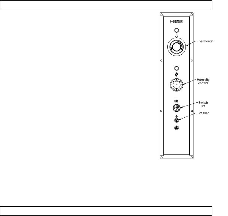
OPERATION OF THE PROOFER
1.Switch "ON" (1).
2.Set the thermostat control at 100° F.
3.Set the humidity control at approximately: 3 for JAOP-3 & JAOP-6
4 or 5 for JAOP-10
5 for JAOP-14
4.If there is too much fog and water drips from the glass doors, adjust humidity control to a lower number.
5.When the temperature is stabilised, put the products in the proofer. (Leave them inside until they are ready to bake.)
6.IMPORTANT: When proofing cycle is completed, turn the humidity switch to "OFF" and let the motor blower and air heat element run for 10-15 minutes to let dry the proofer. Then, turn the main switch ‘’OFF’’ (0) and leave the door ajar to prevent moulding.
When the proofer is not in operation, open the doors to let out the humidity and to prevent mould.
P.S. The doors should not be opened unnecessarily to conserve the heat and humidity in the proofer.
Every day cleaning of the water pan under the proofer's doors should be exercised.
POWER FAILURE
When the power comes back, the proofer will start automatically. Then it’s recommended to turn OFF the unit to avoid it starting without supervision.
 Loading...