


JA5P2618
ÉQUIPEMENT DOYON INC.
1255, rue Principale
Linière, Qc, Canada G0M 1J0
Tel.: 1 (418) 685-3431
Canada: 1 (800) 463-1636
US: 1 (800) 463-4273
FAX: 1 (418) 685-3948
Internet: http://www.doyon.qc.ca
e-mail: doyon@doyon.qc.ca
JA5P1813 - JA5P2618
Product / Produit:
Serial number / Numéro de série:

IMPORTANT SAFETY INSTRUCTIONS
SAVE THESE INSTRUCTIONS
DANGER
TO REDUCE THE RISK OF FIRE OR ELECTRIC SHOCK
CAREFULLY FOLLOW THESE INSTRUCTIONS
TABLE OF CONTENTS
(table des matières :page suivante)
DESCRIPTION________________________________________________________________ A-1
Introduction________________________________________________________________ A-1
Construction _______________________________________________________________ A-1
Shipping __________________________________________________________________ A-1
Installation warnings_________________________________________________________ A-3
Distances to respect__________________________________________________________ A-3
Installation ________________________________________________________________ A-5
Drain instruction ____________________________________________________________ A-5
ECM-1 Programmable control - Operating modes__________________________________ A-7
Manual mode ______________________________________________________________ A-9
Program mode_____________________________________________________________ A-10
Doyon communication software for ECM-1 controller _____________________________ A-21
Troubleshooting ___________________________________________________________ A-25
Oven maintenance and cleaning _______________________________________________ A-29
Bake chart ________________________________________________________________ A-31
COMPONENT PARTS __________________________________________________________B-1
JA5P UP TO S/N #2150 – Front view____________________________________________B-1
JA5P S/N #2200 AND UP – Front view __________________________________________B-3
JA5P UP TO S/N #2150 – Back view ____________________________________________B-5
JA5P S/N #2200 AND UP – Back view___________________________________________B-7
LIGHTS S/N #2200 AND UP __________________________________________________B-9
CONTROL PANELS ____________________________________________________________C-1
JA5P 1/3PH 208-240V 60Hz ___________________________________________________C-1
JA5P [LIVRET].doc 03/10

IMPORTANT INSTRUCTIONS DE SÉCURITÉ
CONSERVEZ CE MANUEL D’INSTRUCTIONS
DANGER
AFIN DE RÉDUIRE LES RISQUES D'INCENDIE OU D'ÉLECTROCUTION
SUIVRE CES INSTRUCTIONS AVEC SOIN
TABLE DES MATIÈRES
DESCRIPTION _________________________________________________________________A-2
Introduction ________________________________________________________________A-2
Construction ________________________________________________________________A-2
Expédition __________________________________________________________________A-2
Avertissement lors de l'installation_______________________________________________A-4
Distances à respecter _________________________________________________________A-4
Installation _________________________________________________________________A-6
Instruction pour le drain_______________________________________________________A-6
Contrôle programmable ECM-1 - Modes d'opération _______________________________A-13
Mode manuel_______________________________________________________________A-16
Mode programmable_________________________________________________________A-17
Logiciel de communication Doyon pour contrôle ECM-1___________________________A-21
Dépannage ________________________________________________________________A-27
Entretien et nettoyage du four__________________________________________________A-30
Tableau de cuisson __________________________________________________________A-32
PIÈCES COMPOSANTE _________________________________________________________B-1
JA5P JUSQU’À S/N #2150 – Vue de face _________________________________________B-1
JA5P S/N #2200 ET PLUS – Vue de face __________________________________________B-3
JA5P JUSQU’À S/N #2150 – Vue arrière _________________________________________B-5
JA5P S/N #2200 ET PLUS – Vue arrière _________________________________________B-7
LUMIÈRES S/N #2200 ET PLUS ________________________________________________B-9
PANNEAUX DE CONTRÔLE _____________________________________________________C-1
JA5P 1/3PH 208-240V 60Hz ___________________________________________________C-1
JA5P [LIVRET].doc 03/10

A-1
SECTION A:
DESCRIPTION
INTRODUCTION
The manufacturer suggests to read this manual carefully.
This equipment is manufactured with first quality material by experienced technicians. Proper installation
and maintenance will guarantee a reliable service for years to come.
A nameplate fixed to the front or right side of the oven specifies the model number, serial number, voltage
and amperage.
Drawings and replacement parts numbers are included in this manual. The electrical diagram is affixed in
the control panel at the back of the oven.
ATTENTION
DOYON is not responsible for damages to the property or the equipment caused by
personnel who is not certified by known organisations. The customer is responsible
for finding qualified technicians in electricity and plumbing for the installation of
the oven.
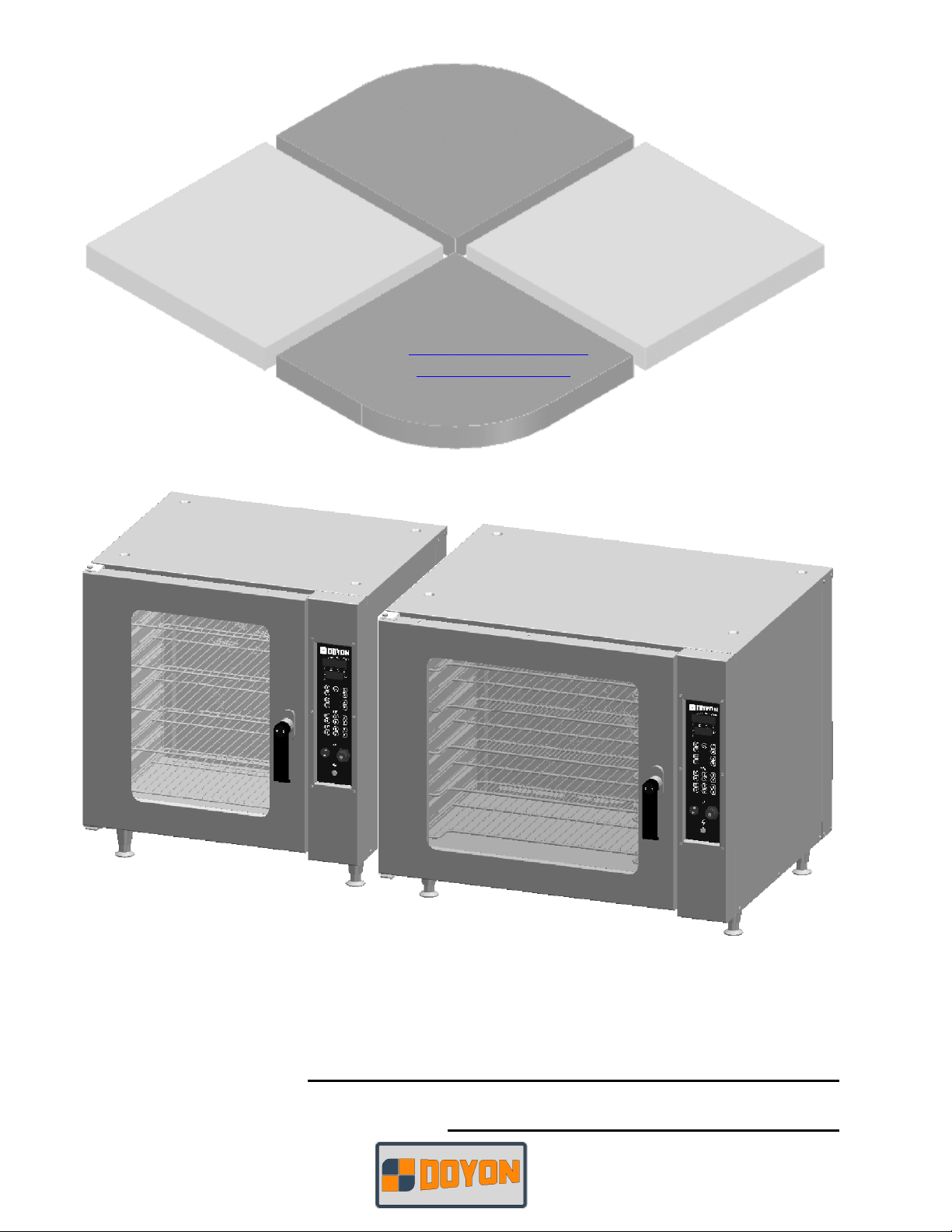
CONSTRUCTION
You just bought the most advanced oven in the world, "DOYON" technology at it’s best. This oven is
manufactured using the highest quality components and material.
The oven gives a perfect uniform baking with its unique Jet Air convection system. The DOYON oven is
designed with parts that are easy to find.
SHIPPING
For your safety, this equipment has been verified by qualified technicians and carefully crated before
shipment. The freight company assumes full responsibility concerning the delivery in good condition of
the equipment in accepting to transport it.
IMPORTANT
RECEPTION OF THE MERCHANDISE
Take care to verify that the received equipment is not damaged before signing the delivery receipt. If a
damage or a lost part is noticed, write it clearly on the receipt. If it is noticed after the carrier has left,
contact immediately the freight company in order that they do their inspection.
We do not assume the responsibility for damages or losses that may occur during transportation.

A-2
DESCRIPTION
INTRODUCTION
Le fabricant suggère de lire attentivement ce manuel et de suivre avec soin les instructions fournies.
Votre équipement est fabriqué avec des matériaux de première qualité par des techniciens
d'expérience. Une utilisation normale et un entretien adéquat de l'équipement vous assureront
plusieurs années de bon service.
Une plaque signalétique, située sur le coin avant droit ou le côté droit du four, mentionne le numéro de
modèle, le numéro de série, la tension et l'ampérage.
Les dessins et les numéros de pièces de rechange sont inclus dans ce manuel. Le plan électrique est
affiché dans la boîte de contrôle à l'arrière du four.
ATTENTION
Équipement Doyon Inc. ne peut être tenu responsable pour les dommages causés à la
propriété ou à l'équipement par du personnel non certifié par des organismes
accrédités. Le client a la responsabilité de retenir les services d'un technicien
spécialisé en électricité et d'un plombier qualifié pour l'installation du four.
CONSTRUCTION
Vous avez maintenant en votre possession le four le plus performant présentement disponible sur le
marché, un four utilisant la technologie "DOYON" à son meilleur. Ce four est fabriqué avec des
matériaux de première qualité.
Avec son système unique de convection «Jet Air», ce four vous permettra d'obtenir une cuisson uniforme.
Le four Doyon est fabriqué avec des matériaux et pièces composantes facilement disponibles sur le
marché.
EXPÉDITION
Pour votre protection, cet équipement a été vérifié et emballé avec précaution par des techniciens
qualifiés avant son expédition. La compagnie de transport assume la pleine responsabilité concernant
la livraison de cet équipement en bon état en acceptant de le transporter.
IMPORTANT
RÉCEPTION DE LA MARCHANDISE
Avant de signer le reçu de livraison, prenez soin de vérifier dès la réception si l'équipement n'est pas
endommagé. Si un dommage ou une perte est détecté, écrivez-le clairement sur le reçu de livraison ou
votre bon de transport et faites signer le livreur. Si le dommage est remarqué après le départ du
transporteur, contactez immédiatement la compagnie de transport afin de leur permettre de constater
les dommages causés.
Nous ne pouvons assumer la responsabilité pour les dommages ou les pertes qui pourraient survenir
pendant le transport.
A-3
INSTALLATION WARNINGS
POWER FAILURE WARNING
WHEN YOU HAVE A POWER FAILURE, SHUT OFF THE OVEN POWER SWITCH TO
PROTECT THE ELECTRONIC COMPONENTS WHEN THE POWER COMES BACK.
FOR YOUR SAFETY
DO NOT STORE OR USE GASOLINE OR OTHER FLAMMABLE VAPORS
AND LIQUIDS IN THE VICINITY OF THIS OR ANY APPLIANCE.
INSTALLATION AND SERVICE
WARNING
IMPROPER INSTALLATION, ADJUSTMENT, ALTERATION, SERVICE OR
MAINTENANCE CAN CAUSE PROPERTY DAMAGE, INJURY OR DEATH.
READ THE INSTALLATION, OPERATING AND MAINTENANCE INSTRUCTIONS
THOROUGHLY BEFORE INSTALLING OR SERVICING THIS EQUIPMENT.
Installation and service must be done by specialised technicians. Contact a certified electrician and
plumber for set up.
The oven must be connected to the utility and electrically grounded in conformity to the effective local
regulations. If these are not established, the oven must be connected according to the Canadian
Electrical Code (CSA-C22.1-XX) or National Electrical Code (NFPA 70-XX). Refer to last edition
year for XX. Installation must also allow proper access for service (24 inches each side and back).
The ovens must be installed with a proper ventilation according with the local building code.
DISTANCES TO RESPECT
A) Back and sides of the oven: 0 inch.
B) Top of the oven: a clearance of 12 inches to the ceiling must exist to allow adequate venting.
C) Floor: 4 inches minimum.
D) Sides of the oven: do not install other than easily removable equipment for service and
maintenance (not closer than 1 inch).
E) It is recommended to have a certain length of water pipe, electric cable between oven and wall
to help gain access for service.
A-4
AVERTISSEMENT LORS DE L'INSTALLATION
PANNE ÉLECTRIQUE
LORS D'UNE PANNE ÉLECTRIQUE, FERMER L'INTERRUPTEUR DU FOUR POUR
PROTÉGER LES COMPOSANTES ÉLECTRONIQUES.
POUR VOTRE SÉCURITÉ
NE PAS EMMAGASINER OU UTILISER D'ESSENCE OU AUTRES VAPEURS
ET LIQUIDES INFLAMMABLES À PROXIMITÉ DE CET ÉQUIPEMENT
OU DE TOUT AUTRE APPAREIL.
INSTALLATION ET SERVICE
AVERTISSEMENT
UNE INSTALLATION, UN AJUSTEMENT, UNE ALTÉRATION, UN SERVICE OU UN
ENTRETIEN NON CONFORME AUX NORMES PEUT CAUSER DES DOMMAGES À LA
PROPRIÉTÉ, DES BLESSURES OU LA MORT. LIRE ATTENTIVEMENT LES DIRECTIVES
D'INSTALLATION, D'OPÉRATION ET D'ENTRETIEN AVANT DE FAIRE L'INSTALLATION
OU L'ENTRETIEN DE L'ÉQUIPEMENT.
L'installation et le service doivent être faits par un technicien spécialisé. Contactez un technicien
spécialisé en électricité.
Cet appareil doit être branché et mis à la terre (grounded) conformément aux règlements effectifs de votre
localité. Si aucune réglementation n'est établie, le four doit être branché conformément au Code
Canadien de l’électricité CSA 22.1-XX ou au Code National de l'Électricité NFPA 70-XX. Référez-vous à
l’année de la dernière édition pour XX. L'installation doit aussi permettre un accès suffisant pour
effectuer le service sur l'équipement (24 pouces sur toutes les faces).
Le four doit être installé sous une ventilation adéquate respectant les norme locales.
DISTANCES À RESPECTER
A) Arrière et côtés du four : 0 pouce.
B) Dessus du four : Il est obligatoire d'avoir au moins 12 pouces entre le dessus du four et le
plafond de manière à permettre une ventilation adéquate.
C) Plancher : Une distance de 4 pouces minimum.
D) Les côtés du four : Installer uniquement des équipements légers et faciles à déplacer pour être en
mesure d'effectuer l'entretien de l'appareil (1 pouce minimum).
E) Il est recommandé d'installer une longueur supplémentaire de tuyau d'eau, de câble électrique
entre le four et le mur pour faciliter l'accès au technicien.

A-5
INSTALLATION
IN GENERAL
Take off the packaging material with care. Take off all the material used for packing and accessories.
If the equipment is delivered with casters, always lock them after installation and use flexible wire. It
must also be installed with restraining device (chain comes with the oven) to guard against transmission
of strain to the gas supply and connectors.
1. To the electrician
Electrical supply installation must be in accordance with the electrical rating on the nameplate.
WARNING
The electrician must make sure that the supply cable does not come in contact with
the oven top which becomes hot.
2. To the plumber
This equipment is to be installed to comply with the applicable federal, state or local plumbing codes.
Connect the steam system (1/4 NPT) to the cold water distribution network.
We highly recommend to use a water softener to eliminate minerals in the water.
We suggest you to use CUNO # CFS6135 (Doyon part number PLF240).
WARNING
Do not adjust the needle valves, it has been done at the factory.
DRAIN INSTRUCTION
At the rear center of the oven there is a gravity drain connection . When the oven leaves the factory this
drain is closed with 2 caps one in the inside of the oven and one at the outside of the oven in case that
this drain is not needed .
If you need to use this drain remove the caps from the inside and install the filter that is situated at the
left side of the back panel.
IMPORTANT: For the outside drain it is very important that the drain is directed towards the floor and
should reach the floor drain.
The drain must also vented and be conformed to the local code.

A-6
INSTALLATION
EN GÉNÉRAL
Ouvrir avec soin l'emballage de votre équipement. Enlever tous les matériaux utilisés pour
l'envelopper ainsi que les accessoires.
Si l'appareil est muni de roulettes, veuillez toujours les bloquer après l'installation et utiliser un cordon
flexible. De plus, des équipements de retenues (chaîne comprise avec le four) doivent être installés
pour empêcher le tuyau d'alimentation et les connecteurs de subir des tensions lorsque le four est
déplacé.
1. À l'électricien
L'installation de l'alimentation électrique des fours doit être conforme avec la source électrique
spécifiée sur la plaque signalétique de l’appareil.
AVERTISSEMENT
L'électricien doit s'assurer que le câble d'alimentation ne touche pas le dessus du four
à cause du degré élevé de chaleur dégagée par celui-ci.
2. Au plombier
Relier le système de vapeur (1/4 NPT) au réseau de distribution d'eau froide.
Il est fortement recommandé d'installer un adoucisseur d’eau à l’entrée de l’appareil afin d’éliminer
les minéraux dans l’eau.
Nous recommandons la marque CUNO # CFS6135 (numéro de pièce DOYON PLF240).
AVERTISSEMENT
Ne jamais changer l'ajustement des valves à aiguille pré-ajustées.
INSTRUCTION POUR LE DRAIN
Le four possède un raccordement de drain par gravité à l'arrière du four (au centre). À la sortie de
l'usine, ce drain est fermé à l’aide de bouchons (intérieur et extérieur) dans le cas où celui-ci ne sera
pas utilisé.
Pour l’utilisation du drain, enlevez le bouchon à l’intérieur du four, installer le filtre qui est situé à
l’arrière du four à gauche.
IMPORTANT: La sortie du drain doit être dirigé en bas vers le plancher, et devrait se rendre
directement à un drain de plancher.
Le drain doit posséder évent et le raccordement doit être conforme aux normes locales.
A-7
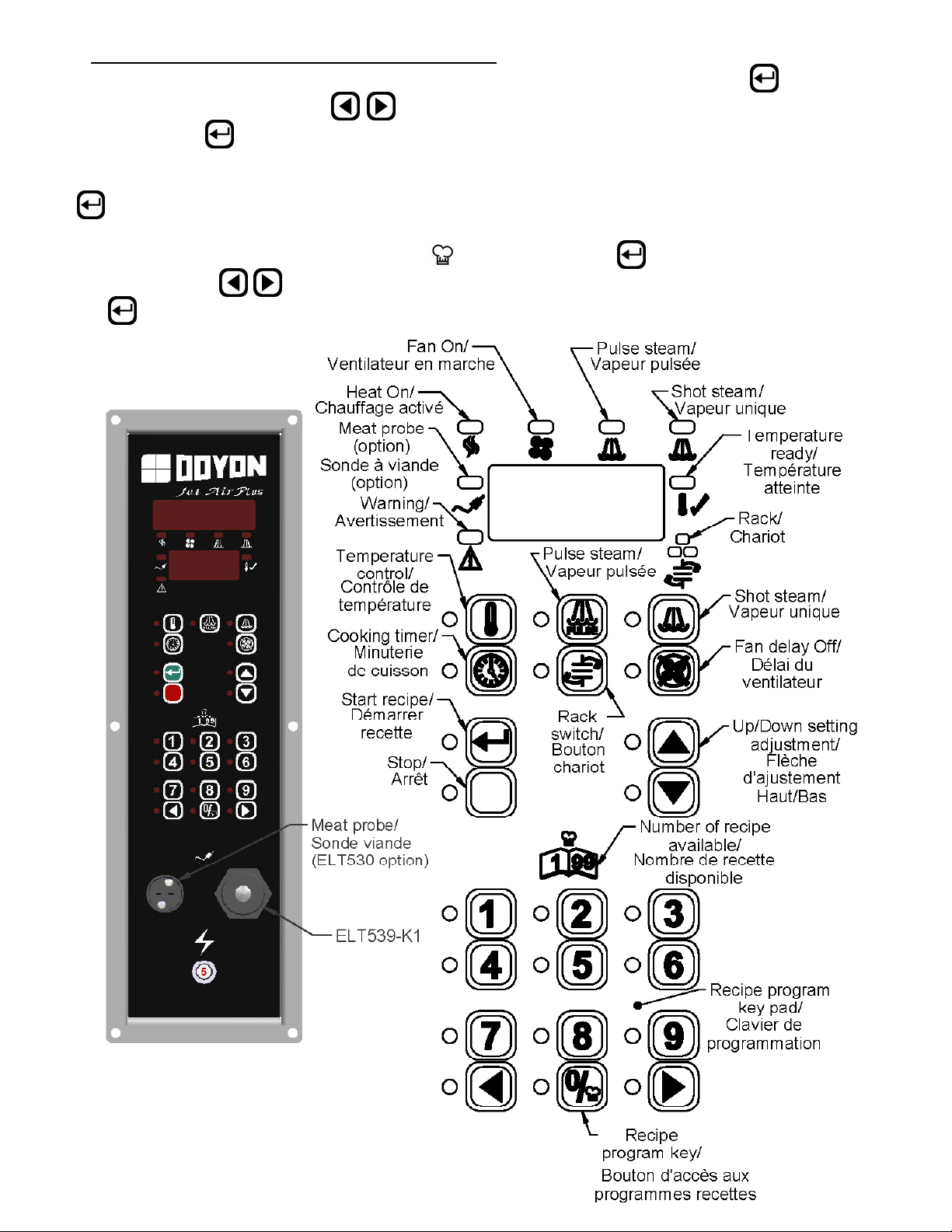
ECM-1 PROGRAMMABLE CONTROL - OPERATING MODES
The Doyon ECM-1 controller has two operation modes Manual and Programmable.
MANUAL: to use all functions without using recipe program.
PROGRAMMABLE: to use with recipe cook program.
Program capacity
□ Programs #1 to #99 can have up to 10 steps each (low-level programmable).
□ Program #0 is always used as the default Manual Cook mode setting (single-step).
OFF MODE
Display/LED
□ Display shows OFF.
□ All other LEDs are off, except the
Press on (start) when the oven is ON, the oven will run on preheat mode at the manual mode set
point (except if you select a cook program referred in How to Select a Cook Program or the Manual
Mode section).
To switch the oven OFF Press the RED stop button and hold it for 3 seconds. The oven will run on
cool down mode until it reaches 250°F and then switch OFF.
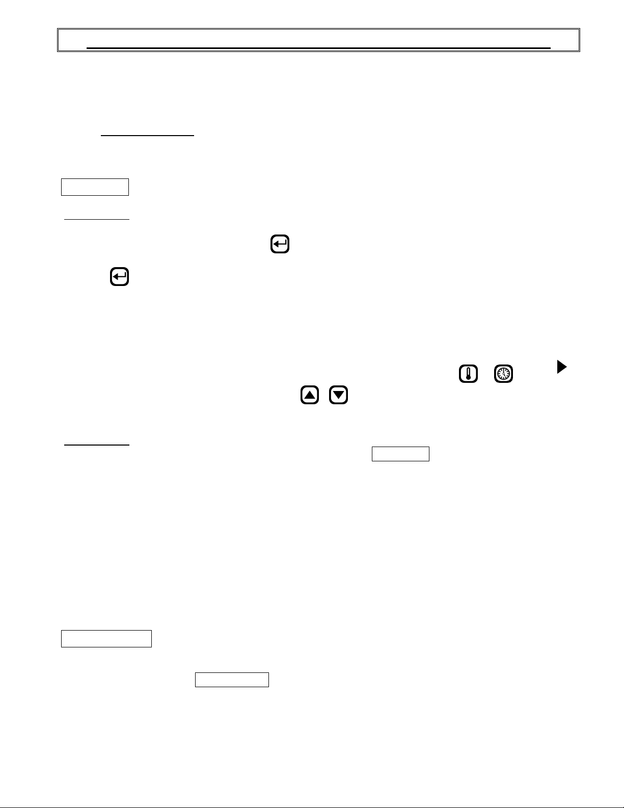
To change the temperature set point or timer setting press and hold for 3 sec. on
appears on the left side of the display, press on / (up / down) to select the desired temperature
set point or timer setting. The new set point or time setting will be automatically saved after 3 seconds.
Display/LED
□ Display scrolls current cook program name (by default MANUAL if no program yet selected).
□ 2nd line shows actual oven temperature.
□ Heat and Fan, LED follows output state.
□ Ready LED blinks.
□ Stop LED is on.
This is the default mode when the controller powers up.
Start key LED.
or
. When
When probe temperature reaches set point, the unit beeps 5 seconds, the ready LED stays on and the
oven goes into COOK MODE.
When the oven is ON, a 3 second long press of red Stop key will go to Cool Down mode if the oven
temperature is over 250°F / 120°C before going to OFF mode. If the temperature is bellow 250°F /
120°C, the oven goes directly to the OFF mode.
DOOR SWITCH
□ If door is opened:
○ Display scrolls DOOR OPEN.
○ All outputs are turned off (unless in Cool Down mode, then fan remains on).
○ All timers pause until the door is closed.
□ When the door is closed, a short delay must expire before all accessories resume normal
operation.
A-8
How to select a cook program or the Manual Mode
To select a recipe program, enter the recipe number with the numeric keypad and press (Start) or
use the Next or Previous arrow
confirm with the (Start) key.
When the recipe is selected, it will be active in the preheat mode until the set point in the first step is
reached. The LED of the red Stop key will light. The recipe will start only when the LED of the key
(Start) is lit.
To go back to the Manual Mode, press on the key and then on the (Start) key or use the Next
or Previous arrow
key (Start).
to jump from one to an other program without having to confirm with the
to jump from one to an other program without having to
A-9
MANUAL MODE
This mode is used to work one step program.
Press on (Start) when the oven is ON, the oven will run on preheat mode at the manual mode set
point (by exception if you select a cook program referred in the PROGRAM MODE section).
TEMPERATURE FUNCTION
To change the temperature set point, press and hold for 3 sec. on . When
side of the display, press on / (Up / Down) to select the desired temperature set point. The new
set point will be automatically saved after 3 seconds.
TIMER FUNCTION
To change the time setting, press and hold for 3 sec. on
display, press on
automatically saved after 3 seconds.
□ If time is less than 60 minutes, it will be displayed as MM.SS
□ If time is 60 minutes or more, it will be displayed as HH:MM
FAN DELAY FUNCTION
□ The fan is always in function, but you can delay the fan for 5 minutes by pressing the Delay
key . After this delay, the fan will run normally.
By pressing a second time on the key before the end of the delay, the fan will remain in function.
STEAM GENERATION FUNCTION
/ (Up / Down) to select the desired time setting. The new time setting will be
When
.
appears on the left side of the
appears on the left
□ Steam output can be turned on only if oven’s temperature >= steam threshold
(300°F /149°C).
□ Steam output can be turned on only if fan is on PULSE
○ Pulse Steam : will turn on and off the steam output continuously if pressed again.
○ Shot steam : steam output is turned on for duration of preset time.
□ Note: Steam and Pulse-Steam in Manual Mode will force Fan On.
FUNCTION CHARIOT
This function is available only with ovens using a rotating rack. This function allows to start and stop
the rack.
Food Probe in Manual Mode
○ When activated, the food probe temperature can only be used in mode MONITOR ONLY.
This will indicate the internal food temperature, not the cooking. To control cooking, use the
Programming mode.
or ON.
A-10
PROGRAM MODE
This mode is used to program a Cook Recipe.
Cook Program structure
A cook program consists of a name as well as a number of steps. The name is pre-programmed into the
unit (each name can have up to 30 characters). Each step has the following programmable parameters:
Oven temperature: the oven set point for this step.
Food temperature: the food temperature at which this step will end.
Time: the time duration for the current step.
Steam: the time steam is injected into the oven at the beginning of the step.
Fan: fan mode.
Aux.: on or off during step (only programmable via PC).
Rack: on or off during step.
Step End: user action needed at the end of step.
Programming
LED/Display
□ 1st line displays currently selected parameter’s value.
□ 2nd line displays current step.
Keys
□ To program or modify a recipe program, select the recipe name first, press and hold for 3
seconds on the Program key. This will give you access to the recipe program. If no change
is made in the recipe during more than 5 seconds, the controller will exit the recipe program
mode by itself and go back to standby mode.
□ All parameters can be programmed in any order within a step.
To program or modify a recipe, follow these steps :
□ Use the parameter keys (Temperature, Time, Steam, Pulse-Steam, Fan, Rack, or Step End) to
display and change its value.
○ Temperature key is used twice to program 2 parameters: Oven Set Point and Food
Temperature.
□ Use the Up / Down keys to change the current parameter.
□ Use the Previous / Next keys to change the current step number.
□ If Step End key is set to LAST
more steps may follow in the program.
□ After last step is programmed, hold the
mode.
Valid programming ranges
Temperature
□ 50-500°F / 10-260°C
Food Temperature
□ 125-225°F / 51-107°C, must be enabled in Low-level programming to be used.
Time
□ Time is programmed in HH:MM.SS
□ Time can be programmed at any value between 00:00 minimum and 12:00 maximum.
□ Default is 00:00
for all steps / programs.
, it is considered to be the last step of the program even though
Program key for 3 seconds to exit programming
A-11
Steam
□ 1st parameter can be: OFF, ON, PULSE.
○ If OFF, steam remains off for duration of step.
○ If ON, steam remains on for duration of step.
○ If PULSE, pulsed steam is enabled for duration of step.
□ Default is OFF for all steps / programs (no steam).
Pulse-Steam
□ Steam parameter (see above) must be set to PULSE.
□ Pressing Pulse-Steam allows programming TON 0.02 seconds by default.
□ Pressing Pulse-Steam a 2nd time allows programming TOFF 0.30 seconds by default.
□ Default is OFF for all steps / programs (no steam).
Fan
□ 1st parameter can be: OFF, ON, PULSE.
○ If OFF, fan remains off for duration of step.
○ If ON, fan remains on for duration of step.
○ If PULSE
, pulse fan is enabled (pulse mode for duration of step).
■ Pressing Fan a 2nd time allows programming TON 02.30 minutes by default.
■ Pressing Fan a 3
rd
time allows programming TOFF from 0.25 seconds by default.
□ Default is PULSE for all steps/programs.
Rack
(Functional only with oven models with rotating racks).
□ Rack must be enabled in low-level programming to be useable.
□ This can be ON or OFF for each step.
□ Default is ON for all steps / programs, if enabled in low-level programming.
Step End
□ Step End defines what happens with the end of a Cook Program Step (Stop key is used to
program Step End parameter).
○ AUTO: nothing happens, automatically move on to the next step (buzzer output remains
off).
○ WARN: move on automatically to the next step, but turn on buzzer output for 5 seconds.
○ MANUAL: activates buzzer output until user manually presses Start key to enable next
step.
○ LAST: activate buzzer output until user manually presses Stop key to end the recipe.
□ Default is AUTO
for all steps / programs.
Food Probe in Programming Mode
□ Food temperature can be programmed to the following settings OFF ON MONITOR.
○ ON
: using food temperature’s programming set point to end the current step at that
temperature.
○ OFF: default for all steps / programs.
○ MONITOR
: to ignore food probe temperature, but still display the information if requested.

A-12
COOK MODE
this mode can cook without using the timer.
Display/LED
□ The 1st line display depends on which view is selected:
○ Time View
○ Temperature View
○ Default View:
□ 2nd line shows current step number if oven is active.
□ Heat, Fan, Steam LED follows output state.
Keys
□ Note : Any changes to the various oven parameters in this mode will not be stored, but will
□ Press Temperature key to toggle the current view between Default, Cavity Probe and Food
Probe.
□ Press Time key:
○ Recipe active: toggles between default and remaining step time.
○ Last Step: toggles between the default and holding time.
□ 3-second long press of Temperature key to change set point (using Up/Down keys).
○ If enabled, a second press of the Temperature key will display the food probe setting.
□ 3-second long press of Time key to change timer’s value (using Up/Down keys).
□ Press Start key to start timer countdown (and rack rotation, if enabled).
□ 3-second long press of Next key to skip to next step.
□ 3-second long press of Previous key to go back to previous step.
□ Press Stop key to cancel countdown and return to idle.
□ 3-second long press of Stop key to go into Cool Down mode.
□ In Manual Mode only, Fan, Rack, Steam and Auto-Steam keys can be used to toggle their
respective output states.
□ Auto-Steam key will start/stop the auto-steam according to Low-level Steam Override TON and
TOFF parameters.
□ If oven is idle, a 5-second long press of the
currently selected Cook Program (or Manual Program).
□ When last step timer expires, the unit beeps 5 times and displays PRODUCT READY. Pressing
Stop red key will clear the message and resume idle.
When a Cook Program is used, if the timer is inactive, the oven is considered idle (but
it still maintains the set point). In Manual Mode, the timer is used only as a reminder,
■ Current time left in step is displayed, except in the last step, where hold time is
displayed.
■ Cavity temperature.
■ Current program name is displayed, except in last step, where PRODUCT READY
displayed.
simply take effect in the current step. This allows “tweaking” recipes from time to time
due to product variations or other factors. For changes to be stored, program mode must
be used.
Program key will enable Program Mode for the
is
A-13
SYSTEM DIAGNOSTICS
Cavity Probe Alarm
□ Occurs when units detects a defective cavity or food temperature probe.
□ Unit goes into Off mode with error message CAVITY PROBE ERROR or
FOOD PROBE ERROR.
Accessory Failure
□ Occurs when input signal is no longer received.
□ Unit goes into Off mode with error message:
○ Accessory failure input # generates ACCESSORY 1 FAILURE.
○ Accessory failure input # generates OVERHEAT FAILURE over heat alarm in control
compartment (check cooling fan and filter).
LANGUAGE DISPLAY
Three languages are available. To change the language display, the controller must be at OFF mode.
Press and hold the key for 5 seconds and use
□ENGLISH, FRANCAIS, ESPANOL
Only the following message will be changed, you can only change the recipe name by using a PC.
/ keys to select the language.
□ English French Spanish
OFF ARRÊT APAGADO
ON MARCHE MARCHA
PULSE IMPULSION IMPULSO
AUTO AUTOMATIQUE AUTOMATICO
WARN AVERTISSEMENT ADVERTENCIA
MANUAL MANUEL MANUAL
LAST DERNIER ULTIMO
MONITOR MONITEUR MONITOR
COOLING DOWN REFROIDISSEMENT ENFRIAMIENTO
ECONOMY MODE MODE ECONOMIQUE MODO ECONOMICO
DOOR OPEN PORTE OUVERTE PUERTA ABIERTA
PRODUCT READY PRODUIT PRET PRODUCTO LISTO
CAVITY PROBE ERROR ERREUR DE SONDE DE ERROR SONDA DE
CAVITE CAVIDAD
FOOD PROBE ERROR ERREUR DE SONDE DE ERROR SONDA DE
NOURRITURE ALIMENTOS
ACCESSORY FAILURE 1 ECHEC ACCESSOIRE 1 FALLA ACCESORIO 1
ACCESSORY FAILURE 2 ECHEC ACCESSOIRE 2 FALLA ACCESORIO 2
CONTRÔLE PROGRAMMABLE ECM-1 - MODES D'OPÉRATION
Le contrôleur ECM-1 Doyon est doté du mode de fonctionnement manuel et programmable.
MANUEL : pour l’utilisation des fonctions sans avoir de recettes à programmer.
PROGRAMMABLE : ce mode est utilisé pour programmer une recette de cuisson.
Capacité du programme
 Loading...