

Page 1
ÉQUIPEMENT DOYON INC.
1255, rue Principale
Linière, Qc, Canada G0M 1J0
Tel.: 1 (418) 685-3431
Canada: 1 (800) 463-1636
US: 1 (800) 463-4273
FAX: 1 (418) 685-3948
Internet: http://www.doyon.qc.ca
e-mail: doyon@doyon.qc.ca
PIZ3G – PIZ6G
Product / Produit:
Serial number / Numéro de série:
Page 2

IMPORTANT SAFETY INSTRUCTIONS
SAVE THESE INSTRUCTIONS
TABLE OF CONTENTS
SECTION « A » DESCRIPTION PAGE
Introduction. . . . . . . . . . . . . . . . . . . . . . . . . . . . . . . . . . . . . . . . . . . . . . . . . . . . . . . . . . .A1
How to cook your favorite pizza . . . . . . . . . . . . . . . . . . . . . . . . . . . . . . . . . . . . . . . . . . A2
Construction . . . . . . . . . . . . . . . . . . . . . . . . . . . . . . . . . . . . . . . . . . . . . . . . . . . . . . . . . .A4
Shipping . . . . . . . . . . . . . . . . . . . . . . . . . . . . . . . . . . . . . . . . . . . . . . . . . . . . . . . . . . . . . A4
Installation warnings . . . . . . . . . . . . . . . . . . . . . . . . . . . . . . . . . . . . . . . . . . . . . . . . . . . A5
Distances to respect . . . . . . . . . . . . . . . . . . . . . . . . . . . . . . . . . . . . . . . . . . . . . . . . . . . . A7
Installation . . . . . . . . . . . . . . . . . . . . . . . . . . . . . . . . . . . . . . . . . . . . . . . . . . . . . . . . . . . A8
Instruction and operation of the oven . . . . . . . . . . . . . . . . . . . . . . . . . . . . . . . . . . . . . . A10
Front control panel symbol description. . . . . . . . . . . . . . . . . . . . . . . . . . . . . . . . . . . . A12
Troubleshooting . . . . . . . . . . . . . . . . . . . . . . . . . . . . . . . . . . . . . . . . . . . . . . . . . . . . . . A13
Oven maintenance and cleaning . . . . . . . . . . . . . . . . . . . . . . . . . . . . . . . . . . . . . . . . . . A15
SECTION « C » BURNER AJUSTMENTS
PIZ3G NATUREL .. . . . . . . . . . . . . . . . . . . . . . . . . . . . . . . . . . . . . . . . . . . . . . . . . . . . C1
PIZ3G PROPANE .. . . . . . . . . . . . . . . . . . . . . . . . . . . . . . . . . . . . . . . . . . . . . . . . . . . . C2
PIZ6G NATUREL . . . . . . . . . . . . . . . . . . . . . . . . . . . . . . . . . . . . . . . . . . . . . . . . . . . . C3
PIZ6G PROPANE . . . . . . . . . . . . . . . . . . . . . . . . . . . . . . . . . . . . . . . . . . . . . . . . . . . . . C4
SECTION « E » COMPONENT PARTS
PIZ3G FRONT . . . . . . . . . . . . . . . . . . . . . . . . . . . . . . . . . . . . . . . . . . . . . . . . . . . . . . . E1
PIZ3G BACK . . . . . . . . . . . . . . . . . . . . . . . . . . . . . . . . . . . . . . . . . . . . . . . . . . . . . . . . E3
PIZ6G FRONT . . . . . . . . . . . . . . . . . . . . . . . . . . . . . . . . . . . . . . . . . . . . . . . . . . . . . . . E5
PIZ6G BACK . . . . . . . . . . . . . . . . . . . . . . . . . . . . . . . . . . . . . . . . . . . . . . . . . . . . . . . . E7
SECTION « F » CONTROL PANELS
PIZ6G - 120V/1PH . . . . . . . . . . . . . . . . . . . . . . . . . . . . . . . . . . . . . . . . . . . . . . . . . . . . F1
PIZ6G - 120V/208V/1PH & 120V/240V/1PH . . . . . . . . . . . . . . . . . . . . . . . . . . . . . . . F3
PIZ6G - 120V/208V/3PH & 120V/240V/3PH . . . . . . . . . . . . . . . . . . . . . . . . . . . . . . . F5
PIZ6G - 220V/1PH/50 Hz . . . . . . . . . . . . . . . . . . . . . . . . . . . . . . . . . . . . . . . . . . . . . . . F7
PIZ3G - 120V/1PH/60Hz . . . . . . . . . . . . . . . . . . . . . . . . . . . . . . . . . . . . . . . . . . . . . . . . F9
PIZ3G - 208-240V/1PH/60Hz . . . . . . . . . . . . . . . . . . . . . . . . . . . . . . . . . . . . . . . . . . . . F11
Warranty . . . . . . . . . . . . . . . . . . . . . . . . . . . . . . . . . . . . . . . . . . . . . . . . . . . . . . . . . . . . .
CAUTION
In case of strong gas odours, shut off the gas input valve
and contact a specialised gas technician
PIZG-A.doc 09/09
Page 3

A1
INTRODUCTION
The manufacturer suggests to read this manual carefully.
This Jet Air gas fired oven is manufactured with first quality material by experienced technicians.
Proper installation and maintenance will guarantee a reliable service for years to come.
A nameplate fixed to the front or right side of the oven specifies the model number, type of
combustible, BTU rating, operating pressure, serial number, voltage and amperage.
Drawings and replacement parts numbers are included in this manual. The electrical diagram is
affixed in the control panel at the back of the oven.
ATTENTION
DOYON is not responsible for damages to the property or the equipment caused
by personnel who is not certified by known organisations. The customer is
responsible for finding qualified technicians in gas, electricity and plumbing for
the installation of the oven.
Page 4

HOW TO COOK YOUR FAVORITE PIZZA
(Pan pizza or regular pizza)
How to cook pan pizza in ovens:
Models: PIZ3,PIZ3G, PIZ6, PIZ6G
(Pizza Hut style)
1. Mix your favorite pizza dough formula.
2. When mixing is done:
A. Cut dough in pieces and make balls.
B. Put the dough balls in a plastic basket with a cover.
C. Place in a cooler or refrigerated room for 12 hours.
D. After 12 hours:
1) Remove dough balls from cooler or refrigerated room.
2) Spray the pizza pan with vegetable oil or olive oil.
3) Shape and set pizza dough in the pan.
4) Transfer pizza pan to proofer unit for 45 to 60 minutes.
Proofer set at: 100oF heat, 85% humidity.
5) When pizza dough is ready, put pizza pan with the cover on, back in the cooler.
6) When ready to bake:
A2
• Take the pizza dough from the cooler;
• Put topping on pizza dough;
• Place the pizza in the oven without cover.
Important: If you cook your pizza in a pan or on a screen, the bottom crust will not bake
properly. If you use them, remove the pizza from the pan or the screen after
3 minutes and finish baking it directly on the oven deck.
Oven baking instructions:
• Preheat at 4650F.
• Baking time:
5-6 mins: 6” 9” 12”
6-8 mins: 16” 18”
Special notice: If you bake only pan pizza or bake on a screen, we recommend using the
following with the oven:
3 grills (optional): Ask your sale representative.
Page 5
A3
How to cook regular pizza:
(No pan or screen)
• Preheat oven at 4650F.
• Remove dough balls from cooler one hour before using.
• For better results:
Dough must be 50
Bake directly on perforated nickel plate.
Baking time at 465
5-6 mins: 6” 9” 12”
0
F to 800F.
0
F:
6-7 mins: 16” 18”
Important: Do not cook with screens.
Cook directly on the perforated nickel deck of the oven.
Cleaning:
We recommend to clean the oven every day.
1) Remove the lower shelf and clean the bottom of the oven with dry cloth and cleaner supplied
with the oven.
2) Glass doors: During working hours, clean glass with dry cloth (paper towel). At the end of the
day, clean with glass cleaner (Windex and paper towel).
NOTICE:
Never put aluminum foil on top of the shelves. This will affect the air circulation and the oven
will not bake properly.
Page 6

A4
CONSTRUCTION
You just bought the most advanced gas fired oven in the world, “DOYON” technology at its best.
This gas fired oven is manufactured using the highest quality components and material.
The oven gives a perfect uniform baking with its unique Jet Air convection system. The DOYON gas
fired oven is designed with parts that are easy to find.
SHIPPING
For your safety, this equipment has been verified by qualified technicians and carefully crated before
shipment. The freight company assumes full responsibility concerning the delivery in good condition
of the equipment in accepting to transport it.
IMPORTANT
RECEPTION OF THE MERCHANDISE
Take care to verify that the received equipment is not damaged before signing the delivery receipt. If
a damage or a lost part is noticed, write it clearly on the receipt. If it is noticed after the carrier has
left, contact immediately the freight company in order that they do their inspection.
We do not assume the responsibility for damages or losses that may occur during transportation.
Page 7

A5
INSTALLATION WARNINGS
The DOYON gas fired ovens are designed to be used with the gas specified on the descriptive
nameplate. Refer to National Fuel Gas Code, ANSI-Z223.1 and CAN/CGA.B149. Copies of these
are available at:
American Gas Association, 1515 Wilson Boulevard, Arlington, Virginia, 22209.
Canadian Gas Association, 55 rue Scarsdale, Don Mills, Ontario, Canada, M3B 2R3.
POWER FAILURE WARNING
WHEN YOU HAVE A POWER FAILURE, SHUT OFF THE OVEN POWER SWITCH TO
PROTECT THE ELECTRONIC COMPONENTS WHEN THE POWER COMES BACK.
FOR YOUR SAFETY
DO NOT STORE OR USE GASOLINE OR OTHER FLAMMABLE VAPORS
AND LIQUIDS IN THE VICINITY OF THIS OR ANY APPLIANCE.
INSTALLATION AND SERVICE
WARNING
IMPROPER INSTALLATION, ADJUSTMENT, ALTERATION, SERVICE OR
MAINTENANCE CAN CAUSE PROPERTY DAMAGE, INJURY OR DEATH.
READ THE INSTALLATION, OPERATING AND MAINTENANCE INSTRUCTIONS
THOROUGHLY BEFORE INSTALLING OR SERVICING THIS EQUIPMENT.
Installation and service must be done by specialised technicians. Contact a certified gas technician,
electrician and plumber for set up.
The oven must be connected to the utility and electrically grounded in conformity to the effective
local regulations. If these are not established, the oven must be connected according to the
Canadian Electrical Code (CSA-C22.1-XX) or National Electrical Code (NFPA 70-XX). Refer to
last edition year for XX. Installation must also allow proper access for service (24 inches each side
and back).
The ovens must be installed with a proper ventilation like:
• under a exhaust vent hood;
• or connected directly to the oven draft hood with a B vent flue pipe chimney.
A type B gas vent approved for use with gas appliances must be utilized.
Make sure that provision for adequate air supply is provided for the operation of the oven.
CAUTION
Make sure that the adjustments mentioned in the “Installation” section are
correctly done prior to firing the oven or converting to a new gas.
Page 8

A6
DISTANCES TO RESPECT
A) Back of the oven: 1 inches.
E.. Top of the oven: a clearance of 12 inches to the ceiling must exist to permit adequate venting
of the exhaust pipe and hot parts and to give proper access to a technician. The draft hood
must have a clearance of 2 inches minimum all around.
E.. Floor: ( 0 ) Clearance.
E.. Sides of oven: do not install other than easily removable equipment for service and
maintenance (not closer than 1 inches).
E.. It is recommended to have a certain length of electric cable and gas pipe between oven and
wall to help gain access for service.
Page 9
A7
INSTALLATION
IN GENERAL
Take off the packaging material with care. Take off all the material used for packing and
accessories. Install the draft hood on the chimney.
Each unit is set up to be used with the type of gas and electrical supply specified on the nameplate
fixed on the front of the oven.
The installation must be conform with the National fuel gas code ANSI Z223.1 and CAN/CGAB149, Gas Installation Code and local Codes where applicable.
The oven’s combustion system consists of a very safe gas burner certified in accordance to the
American Gas Association Standard in USA and with the Canadian Gas Association in Canada.
E.. To the certified gas technician
The burner installed on DOYON gas fired ovens is set up and adjusted at the plant for a first
class operation. It is nevertheless necessary to verify on site the pressure at the burner input.
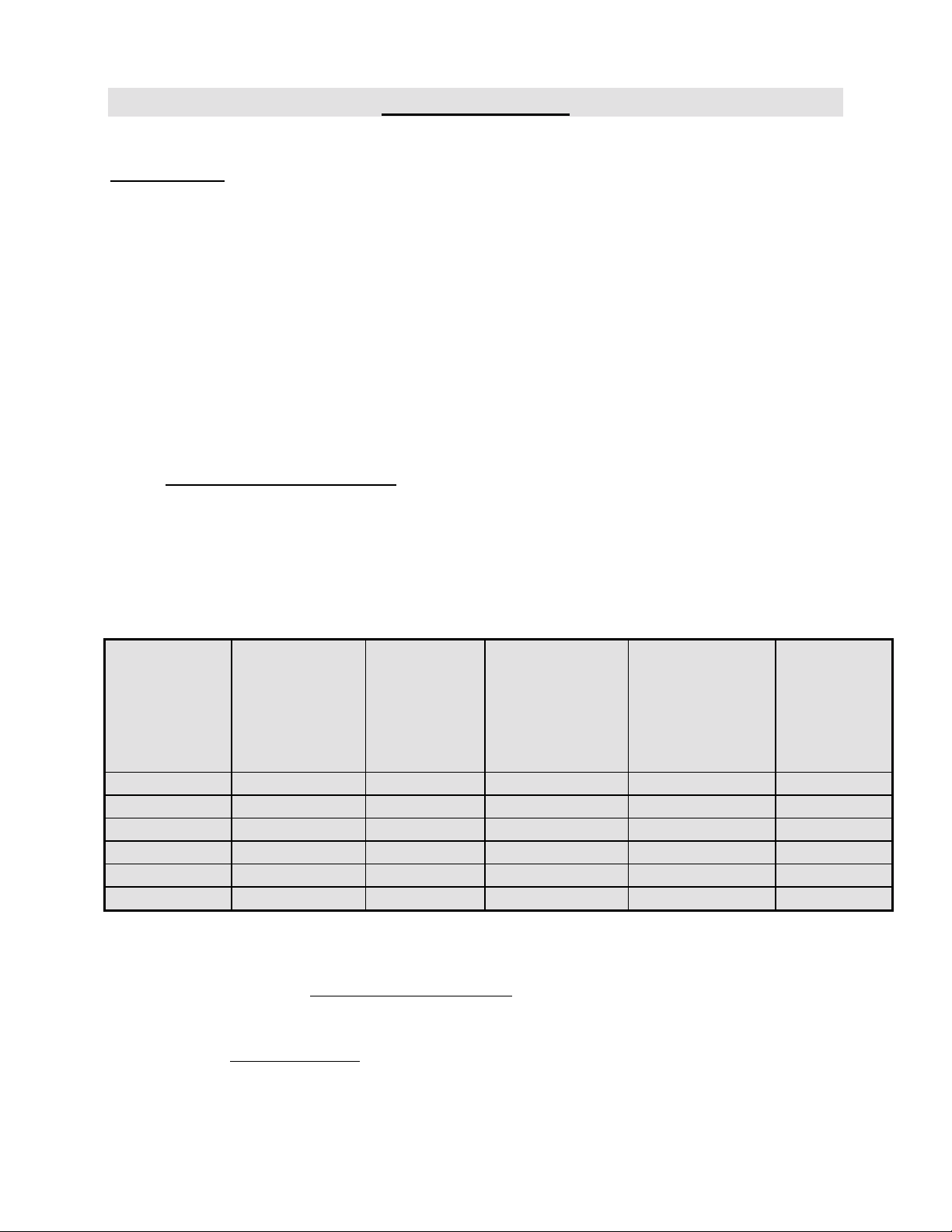
The following table indicates the pressures that must be set up to remain conform to the
A.G.A. standards or C.G.A.
GAS TYPE ALTITUDE
(FT)
PIZ6G Propane 0-4500 70,000 11,0 7,0 37
PIZ6G Natural 0-4500 70,000 7,0 3,3 23
PIZ6G Propane 0-4500 85,000 11,0 7,0 32
PIZ6G Natural 0-4500 85,000 7,0 3,5 17
PIZ3G Propane 0-4500 70,000 11,0 7,0 37
PIZ3G Natural 0-4500 70,000 7,0 3,5 23
The burner used is adjusted to be used with the gas indicated on the nameplate. It is
nevertheless possible to convert the burner to another gas by doing the modifications
indicated in the
modifications must be done carefully and completely under the company’s instruction
to remain conform to A.G.A. or C.G.A standards. Refer to Doyon Equipment to get
the right
CONVERSION KIT.
CONVERSION PROCEDURE provided with the oven. These
INPUT
(BTUH)
REGULATOR
INPUT
PRESSURE
(Water column
inches)
BURNER
INPUT
PRESSURE
(Water column
inches)
BURNER
ORIFICE
SIZE (DMS)
Page 10

A8
The installation must be made with a connector that meets with the standard for connectors movable
gas appliances ANSI Z21.69 and a Quick-disconnect device that complies with the standard for
Quick-disconnect devices for use with gas fuel ANSI Z21.41 and addenda Z21.41a and Z21.41b. It
must also be installed with restraining (chain that came with the oven) to guard against transmission
of strain to the connector. The pipe fittings compound must be certified for gas.
The customer must install a manual shut off valve at the end of the gas supply pipe near the burner
which is approved by the American Gas Association Standard in Canada with the Canadian Gas
Association.
Exhaust: A draft hood is provided with the unit and it must be used when the chimney is directly
connected to a gas vent pipe. The exhaust pipe must be certified for use of gases.
Clean the air contained in the gas supply pipe at the installation to insure a successful firing on the
first try. The gas pipe sealing compound tightness must be verified using a solution of water and
soap prior to firing the unit.
ATTENTION
Make sure not to obstruct the overpressure opening on the gas regulator.
NOTE: If there’s any modification done to the system or change of the type of gas
used, make sure that the regulator pressure of the burner is adjusted as recommended in
this manual.
E.. To the electrician
Electrical supply installation must be in accordance with the electrical rating on the nameplate.
WARNING
The electrician must make sure that the supply cable does not come in contact
with the oven top which becomes hot.
Page 11
A9
INSTRUCTION AND OPERATION OF THE OVEN
“This appliance is only for professional use and should be used by qualified persons only”
1. Open the main gas valve.
2. Turn on the ventilation system if necessary.
3. Turn the oven start switch to the position “1”.( See page A12 for front control
operation description).
• PIZ3G only The yellow light “READY FOR OPERATION” must turn on for a
few seconds (it indicates that every starting condition is present)
• PIZ3G only the blower starts and the burner fires if the thermostat is adjusted over the
ambient temperature (the green light “BURNER” indicates that the burner is fired)
(If nothing happened, press the breakers on the front)
4. Adjust the thermostat at the desired temperature setting, maximum setting adjustment
600°F (see THERMOSTAT INSTRUCTIONS bellow).
5. Wait until the unit reaches the baking temperature (see tables “Pizza baking time”).
• When the desired temperature is reached, the red light (on the thermostat) and the
green light (Burner) goes out then the burner stops.
6. Adjust baking time according to your product (see cooking timer instruction page A11 and
baking time suggestions page A2, A3 ).
Use the arrows up/down on the baking timer.
7. Place your products (see baking instruction page A2, A3).
To have maximum heat transfer bake directly on the nickel plated.
VERY IMPORTANT
This oven has an overheat warning alarm to protect the electrical components against overheating. If
the red pilot light (OVERHEAT WARNING) is lit and you hear a buzzer, see trouble shooting
section.
Page 12
A10
THERMOSTAT INSTRUCTIONS
To obtain a very good thermal stability, we use a digital temperature controller with thermocouple.
The Omron E5CS thermostat controls the heat of every element at the SP (set point).
The temperature of the oven is always shown on the display of the thermostat and an arrow indicates
if the temperature is over or below the SP. When the green light is lit, it indicates that the temperature
is at the SP ± 1 %.
To adjust the SP (set point) value, you just have to press the key on the left and use the up and down
keys to set the temperature. Press the left key to return to run mode.
COOLING FAN
A cooling fan located on front top of the oven run during normal operation of the oven.
A temperature detector (thermodisk) is installed in the control compartment to start the cooling
fan when the temperature rises over 37°C.
PIZ3G FAULT DESCRIPTION
When there is a fault, a buzzer rings and the red light “fault” turns on
It may be caused by
• Too much pressure in burner compartment (blower does not work or does not produce
vacuum) , air pressure switch is not well adjusted or defective.
• Gas pressure is too low or not well adjusted or defective gas pressure switch.
• Malfunction of ignition system or detection of flame.
To correct press the red push button “fault” (same one as the “fault” light) for two second.
If the fault is still active and cannot be reset, call for service.
COOKING TIMER
Set the baking time required with the small push button on the timer. The green display is the setting
time and the red display is the countdown time (Ex: 25 minutes = set 2500 on green display).
After setting: Push the START/STOP button then, when the time expires, the buzzer will ring.
Push the START/STOP button again to stop the buzzer.
If you want to restart the time in the middle of the countdown, press on the START/STOP
button.
P.S. The timer is simply a reminder for the approximate duration of the baking time..
POWER FAILURE
The burner, the electric gas valve and the regulator are all designed to be fail safe. Then, there is
no special action to take in case of electrical power failure. Turn off the oven. Never leave the
oven unsupervised when the power is on the unit.
Page 13
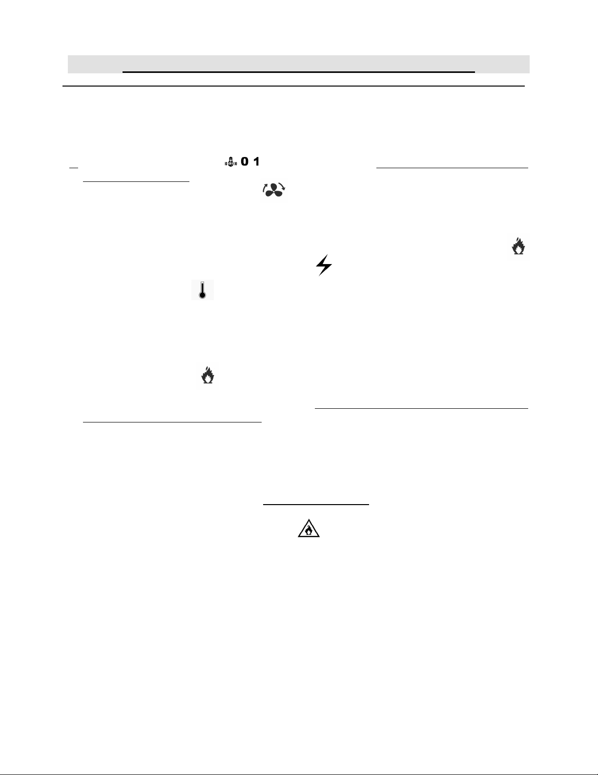
A11
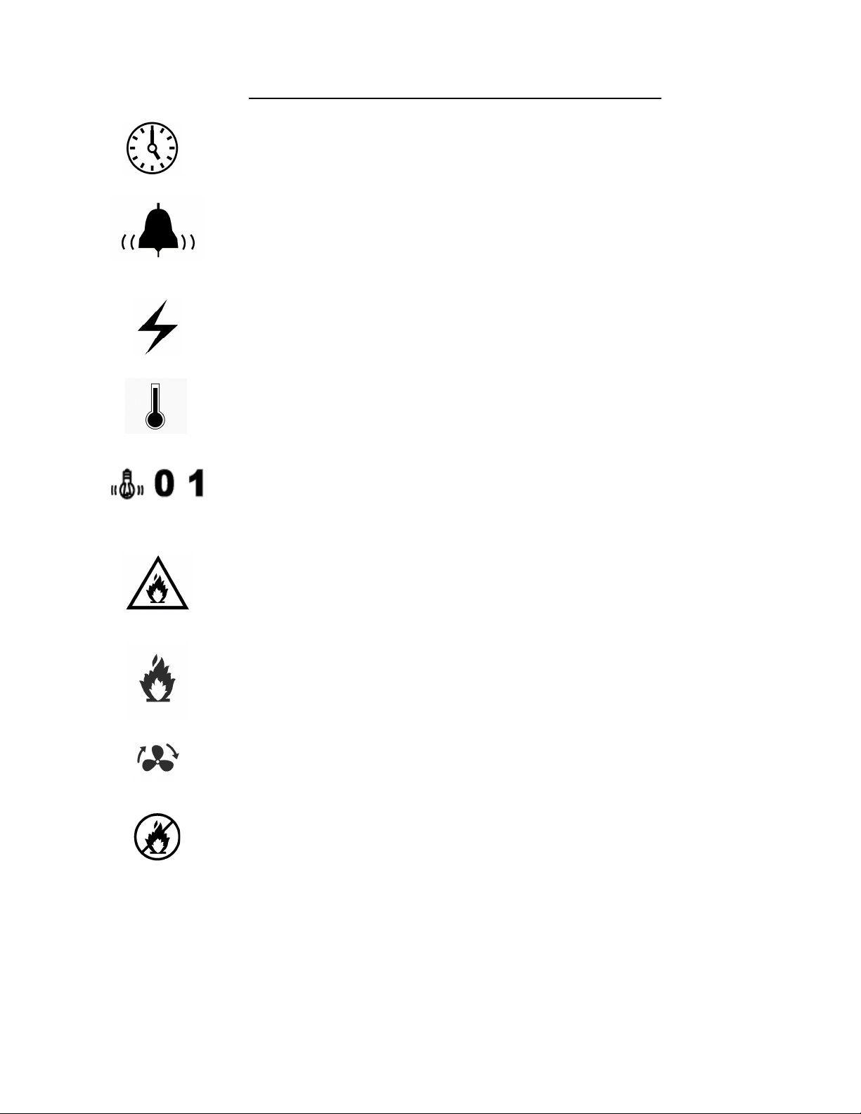
FRONT CONTROL PANEL SYMBOL SIGNIFICATION
Cooking timer
On / off cooking timer switch
Breaker
Temperature control
Main power oven switch (0 = OFF, 1 = ON, bulb sign = Oven light ON only)
Overheat alarm
Burner operation indicator green light
Air proving switch indicator yellow light.
Burner fault reset red light switch.
Page 14

A12
TROUBLESHOOTING
BEFORE CALLING FOR SERVICE
ANSWERS TO MOST FREQUENT QUESTIONS
Always cut off the main power before replacing any parts.
Control parts on the front control:
Gas and motor system on the back of oven:
Questions Solutions
The oven does not turn on.
The oven does not produce heat.
Remove the hood control panel of the oven by
screwing out the screws.
Pull the oven and screw out of the back panels.
Check the breakers on the front panel.
Check the breakers of the building.
Check if the doors are tightly closed.
Check the motor fuses and the overload relays
located in the electrical control panel.
• Make sure the thermostat is adjusted to a
temperature high enough to turn on the pilot
light.
1. If the oven blowers are not on, check the
overload relays located in the control
compartment. If anyone of these is
disengaged, call for a qualified technician.
E.. If the oven blowers are on:
• Check that the manual shut-off valve is open
correctly.
To start it over, simply put the thermostat to the
“OFF” position, wait at least 10 seconds, then
reset it at the desired temperature. The burner
will start up and you can see the flame through
the hole near the gas input. You can repeat this
operation three times. If it does not start up
again, contact our company or a certified gas
technician.
Page 15

A13
• The burner goes to lock-out because of:
E.. Flame failure:
b) The spark is irregular or not present:
c) The air pressure switch does not close its
contact.
Uneven baking
The burner is equipped with multiple
interlocked safety devices. In the event of a
failure of the flame or any blockage of the
combustion air supply, the burner will “lock
out” in the safety condition.
• Air has not been bled from the gas line.
• Porcelain insulators cracked (very little
crack is enough).
• Spark probe grounded.
• It may be disconnected, incorrectly set or
defective or maybe the blower is not
running.
Make sure that the grills do not obstruct the air
flow. Do not use foil on the grills.
Verify the temperature of the oven by using an
oven thermometer and make sure that it is even
with the thermostat setting.
If the oven is baking too much on the sides, it is
possible that the fan is not cycling properly.
Verify if the motor turns 2.5 minutes in a
direction, stops 30 seconds and starts for 2.5
minutes in the opposite direction.
If the OVERHEAT WARNING light is on and
you hear the warning buzzer
Check if the cooling fan airflow is not
obstructed.
Check the cooling fan if it is running. If not,
call a qualified technician to replace it.
(Electrical components may be damaged if it is
not repaired immediately.)
Do not allow any obstruction to free the airflow of the burner.
CAUTION
Never try to modify the burner controls. This must be done only by a qualified
technician and under the company’s instructions.
Page 16

A14
TO REPLACE
SILICONE BUMPER
PART NUMBER
40000030 (QUE500)
CLEAN UNDER
DOOR WEIGHT
UNSCREW THE 7 SCREW S
TO REMOVE THE PANEL
OVEN MAINTENANCE AND CLEANING
MAINTENANCE OF THE BURNER
• Once a year, you should ask a certified technician to make a tune up.
Make sure everything works properly, verify and clean especially:
1. The gas mixer air inlet.
2. The spark rod and porcelain insulators.
3. The flame detection rod.
4. Verify the burner input pressure.
5. Verify every adjustments.
6. Clean every moving pieces.
PIZ6G PIZ3G
4
1
2
3
Step by step Recommendations
Clean the inside of the oven with
water and soap.
Take out the grills (the grills of
the oven could be cleaned with
“Easy-Off”).
After cleaning the inside of the
oven, apply a silicone base oven
protector. It avoids food from
sticking to the metal.
Clean the oven windows with
products like Brasso or
equivalents. They are copper
cleaners but good for this use.
Clean the oven exterior with a
stainless steel cleaner.
1
2
We recommend and sell:
Dirt Buster III : Action foam cleaner
CHEMCO
Part number : NEB201
We recommend and sell:
316 Silicone base protector and
lubricant for oven
Dow Corning
Part number : EXS400
We recommend and sell:
Wright’s: Cream copper cleaner
J.A. Wright & Co.
Part number : EXC300
We recommend and sell:
Stainless steel cleaner.
SANY or CURTIS (comestible)
Part number : NES201
4
3
Page 17

SECTION
C
BURNER ADJUSTMENTS
Page 18

C-1
ON %%1 5/8 [Ø41.28]
8 HOLES Ø7/16 [Ø11.10]
PIECE #2
THICKNESS 1/8 (3.2mm)
PIECE #1
C1
ADJUSTMENT BURNER
PIZ3G NATURAL GAS
2 9/16
[65.09]
5/32
2 3/8
[60.33]
[3.97]
GROUND PLATE
NOZZLE
COMBUSTION−CHAMBER
5/32
THICKNESS 3/32 (2.4mm)
SPACER
#29 (3.5mm)
1
2
(3.9mm)
NOZZLE #23
INSULATION
COMBUSTION−CHAMBER
1 1/4
[31.80]
[3.98]
MINERAL WOOL
PROTECTOR FOR
PIZ3G−N
SUPPLY PRESSURE: 7" W.C. (20/25 Mbar)
MANIFOLD PRESSURE: 3.5" W.C. (8.75 Mbar)
IGNITION WIRE: 30"
HIGH LIMIT: 700° F
DETECTION WIRE: 30"
THERMOSTAT: 600° F
LOCKED: 645° F
BTU: 70 000
Page 19

C-2
ON %%1 5/8 [Ø41.28]
4 HOLES Ø7/16 [Ø11.10]
PIECE #2
THICKNESS 1/8 (3.2mm)
PIECE #1
C2
ADJUSTMENT BURNER
PIZ3G PROPAN GAS
2 9/16
[65.09]
5/32
2 3/8
[60.33]
[3.97]
GROUND PLATE
NOZZLE
COMBUSTION−CHAMBER
5/32
THICKNESS 3/32 (2.4mm)
SPACER
#29 (3.5mm)
1
2
(2.6mm)
NOZZLE #37
INSULATION
COMBUSTION−CHAMBER
1 1/4
[31.80]
[3.98]
MINERAL WOOL
PROTECTOR FOR
PIZ3G−P
SUPPLY PRESSURE: 11" W.C. (28/50 Mbar)
MANIFOLD PRESSURE: 7" W.C. (17.50 Mbar)
IGNITION WIRE: 30"
HIGH LIMIT: 700° F
DETECTION WIRE: 30"
THERMOSTAT: 600° F
LOCKED: 645° F
BTU: 70 000
Page 20

C-3C4C-4
ON %%1 5/8 [Ø41.28]
4 HOLES Ø7/16 [Ø11.10]
ON %%1 5/8 [Ø41.28]
4 HOLES Ø5/16 [Ø7.94]
C3
PIECE #2
THICKNESS 1/8 (3.2mm)
PIECE #1
THICKNESS 3/32 (2.4mm)
INSULATION
ADJUSTMENT BURNER
PIZ6G NATURAL GAS
2 9/16
[65.09]
5/32
2 3/8
5/32
[3.97]
[60.33]
[3.98]
2 1/2
[63.50]
GROUND PLATE
NOZZLE
COMBUSTION−CHAMBER
MINERAL WOOL
COMBUSTION−CHAMBER
SPACER
#29 (3.5mm)
1
2
(3.9mm)
NOZZLE #23
1 1/4
[31.80]
PROTECTOR FOR
PIZ6G−N
SUPPLY PRESSURE: 7" W.C. (20/25 Mbar)
MANIFOLD PRESSURE: 3.3" W.C. (8.25 Mbar)
IGNITION WIRE: 45"
HIGH LIMIT: 700° F
DETECTION WIRE: 36"
THERMOSTAT: 550° F
LOCKED: 645° F
BTU: 70 000
Page 21

Page 22

SECTION
E
COMPONENT PARTS
Page 23

E-1
Page 24

E-2
Item Part Number Description Quantity
1 STPP03 PLATE FOR PIZ3 3
2 QUE100 DOOR GASKET (FIBERGLASS) 3
3 P3106F DOOR OF PIZ3 31 1/8 X 6 3/8 3
4 QUB600 BLACK KNOB FOR OVEN DOOR HANDLE 6
5 ELT725 TRANSFORMER 120-240 > 120-240 250VA 50Hz 1
OR ELT715 TRANSFORMER 120-240 > 120-240 100VA 50Hz 1
6 ELM760 COOLING FAN 120V 1
7 ELB098 2A BREAKER 1
8 ELB096 5A BREAKER 1
9 ELP401 BLACK PUSHBUTTON PUSH-IN PUSH-OUT 1
10 ELI406 BASE WITH 1NO 1
11 ELM617 BLACK COVER FOR ELM616 1
12 ELM629 ELECTRONIC TIMER 8 PIN SOCKET 1
13 ELM618 FIXING FOR PANASONIC TIMER 1
14 ELM616 ELECTRONIC TIMER 1
15 ELI403 BLACK SELECTOR 3 POS. 1
16 ELI413 BASE WITH 2NO 1
17 ELI409 CONTACT BLOCK NC 1
18 ELL405 CONTACT BLOCK NO 1
19 ELL660 RED PILOT LIGHT 250V 1
20 ELL650 RED PILOT LIGHT 250V 1
21 ELL680 GREEN PILOT LIGHT 28V 1
22 ELT515 ELECTRONIC THERMOSTAT 1
23 ELM726 FIXING FOR OMRON TIMER 1
24 ELL411 RED PUSHBUTTON ILLUMINATES LED 1
25 ELL410 RED LED BASE 24V WITH 1NC 1
26 ELS950 BUZZER 120V 2
27 ELT507 HIGH LIMIT SWITCH 110°F 1
28 ELM735 SOLID STATE TIMER ICM 1
29 ELS940 BUZZER 24V 1
30 ELT503 HIGH LIMIT SWITCH 140°F 1
Page 25

E-3
Page 26

E-4
Item Part Number Description Quantity
1 40000030 STOPPER 3/4" FOR DOOR WEIGHT (QUE500) 6
2 GRP005 LEFT HANDLE ASSEMBLED FOR PIZ3 3
3 GRP005A RIGHT HANDLE ASSEMBLED FOR PIZ3 3
4 50088001 DOOR WEIGHT 6
5 ELD088 SOCKET WITH FRAME 77-708 120VOLT 77-708-0126 3
6 GAM200 ATMOSPHERIC MIXER (GAS OVEN EXCEPT TLO) 1
7 GAD190 IGNITION ELECTRODE 1
8 GAP300 PRESSURE SWITCH 1
9 GAD200 DETECTION ELECTRODE 1
10 ELM820ML MOTOR 3/4HP 3PH 208/230/460V 50/60HZ FOR GAS OVEN 1
11 ELT620 THERMOSTAT BEZEL 1
12 ELT681 THERMOSTAT KNOB 700°F 1
13 ELT680 THERMOSTAT 700°F 1
14 GAB500 ELECTRONIC CONTROL BOX FOR GAS OVEN (S87D) 1
15 ELT705 TRANSFORMER 120/240 TO 12/24, 100VA 1
16 GAT100 TRANSFORMER 120/25V 20VA 1
17 PELE0029 PIZ3G 1PH 120V 60HZ 1
18 GAC230 HONEYWELL CARBURATOR (NATURAL, EXCEPT TLO) 1
19 GAC235 SOLENOID GAS VALVE 24V 50/60HZ 1
Note: As of April 2010, part ELD088 (#5) will replace parts ELD050 & ELA275.
Page 27

E-5
Page 28

E-6
Item Part Number Description Quantity
1 STPP06 PLATE FOR PIZ6 3
2 P4107F DOOR PIZ6G 3
3 QUB600 BLACK KNOB FOR OVEN DOOR HANDLE 6
4 ELS950 BUZZER 120V 2
5 ELT507 HIGH LIMIT SWITCH 110°F 1
6 ELT503 HIGH LIMIT SWITCH 140°F 1
7 ELM762 COOLING FAN 250 CFM 120V 1
8 ELB096 5A BREAKER 1
9 ELP401 BLACK PUSHBUTTON PUSH-IN PUSH-OUT 1
10 ELI406 BASE WITH 1NO 1
11 ELM616 ELECTRONIC TIMER 1
12 ELM629 ELECTRONIC TIMER 8 PIN SOCKET 1
13 ELI403 BLACK SELECTOR 3 POS. 1
14 ELI413 BASE WITH 2NO 1
15 ELI409 CONTACT BLOCK NC 1
16 ELL405 CONTACT BLOCK NO 1
17 ELL650 RED PILOT LIGHT 250V 1
18 ELT515 ELECTRONIC THERMOSTAT 1
Page 29

E-7
Page 30

E-8
Item Part Number Description Quantity
1 GRP006 LEFT DOOR HANDLE OF PIZ6 & FPR 3
2 GRP006A RIGHT DOOR HANDLE OF PIZ6 & FPR 3
3 40000030 STOPPER 3/4" FOR DOOR WEIGHT (QUE500) 6
4 50089001 COUNTERWEIGHT 4
5 50088002 COUNTERWEIGHT RIGHT SIDE 1
6 50089004 COUNTERWEIGHT LEFT SIDE 1
7 ELD088 SOCKET WITH FRAME 77-708 120VOLT 77-708-0126 6
8 GAM200 ATMOSPHERIC MIXER (GAS OVEN EXCEPT TLO) 1
9 GAD190 IGNITION ELECTRODE 1
10 GAP300 PRESSURE SWITCH 1
11 GAD200X DETECTION ELECTRODE 1
12 ELT620 THERMOSTAT BEZEL 1
13 ELT680 THERMOSTAT 700°F 1
14 ELT681 THERMOSTAT KNOB 700°F 1
15 GAB500 ELECTRONIC CONTROL BOX FOR GAS OVEN (S87D) 1
16 ELT705 TRANSFORMER 120/240 TO 12/24, 100VA 1
17 GAT100 TRANSFORMER 120/25V 20VA 1
18 ELM820ML MOTOR 3/4HP 3PH 208/230/460V 50/60HZ FOR GAS OVEN 1
19 ELP885
20 GAC230 HONEYWELL CARBURATOR (NATURAL, EXCEPT TLO) 1
21 GAC235 SOLENOID GAS VALVE 24V 50/60HZ 1
OR PANEL 120V 1PH (SEE P120SP6G)
OR PANEL 240V 1PH (SEE P240SP6G)
OR PANEL 208V 3PH (SEE P208SP6G)
CONT. PAN. SIMPLE GAS 120V 1 PH (WITHOUT TIMER, BASE,
BOX)
1
Note: As of April 2010, part ELD088 (#7) will replace parts ELD050 & ELA275.
Page 31

SECTION
F
CONTROL PANELS
Page 32

F-1
1
PIZ6G
F1
120 VOLTS 1 PHASE
2
8
3
4
G:\ACAD10\PANNEAU\FAMPIZ\P120SP6G.dft
7
5
6
Page 33

F2
Item Part Number Description Quantity
1 ELB107 15A BREAKER 1
2 ELL050 GROUND LUG 1
3 ELB073 TERMINAL BLOCK 30A 11
4 ELM715 PRESET TIMER 25SEC. OFF - 150SEC. ON 1
5 ELO100 OVERLOAD 7 TO 10 Amps. 1
6 ELO125 OVERLOAD BASE RELAY TÉLÉMÉCANIQUE 1
7 ELC495 MOTOR REVERSING CONTACTOR 2HP 1
8 ELB071 TERMINAL BLOCK 2P 175A 1PHASE 1
Model : P120SP6G View : INSIDE (See OVEN BACK)
Page 34

PIZ6G
F-3
F3
120/208 OR 120/240 VOLTS 1 PHASE
1
8
2
7
3
4
G:\ACAD10\PANNEAU\FAMPIZ\P240SP6G.dft
5
6
Page 35

F4
Item Part Number Description Quantity
1 ELB125 DOUBLE POLE BREAKER 8A 1
2 ELL050 GROUND LUG 1
3 ELB073 TERMINAL BLOCK 30A 11
4 ELM715 PRESET TIMER 25SEC. OFF - 150SEC. ON 1
5 ELO098 OVERLOAD TELEMECANIQUE 2.5 TO 4 AMPS 1
6 ELO125 OVERLOAD BASE RELAY TÉLÉMÉCANIQUE 1
7 ELC495 MOTOR REVERSING CONTACTOR 2HP 1
8 ELB072 TERMINAL BLOCK 3P 175A 1
Model : P240SP6G(240V PIZ-6-G) View : INSIDE (See OVEN BACK)
Page 36

PIZ6G
F-5
F5
120/208 OR 120/240 VOLTS 3 PHASE
1
7
2
5
3
4
G:\ACAD10\PANNEAU\FAMPIZ\P208SP6G.dft
6
Page 37

F6
Item Part Number Description Quantity
1 ELB121 TRIPLE POLE BREAKER 8A 1
2 ELL050 GROUND LUG 1
3 ELB073 TERMINAL BLOCK 30A 11
4 ELM715 PRESET TIMER 25SEC. OFF - 150SEC. ON 1
5 ELO098 OVERLOAD TELEMECANIQUE 2.5 TO 4 AMPS 1
6 ELC495 MOTOR REVERSING CONTACTOR 2HP 1
7 ELB071 TERMINAL BLOCK 2P 175A 1PHASE 2
Model : P208SP6G (PIZ6G) View : INSIDE (See OVEN BACK)
Page 38

F-7
1
2
PIZ6G
F7
220 VOLTS 1 PHASE
8
9
3
4
G:\ACAD10\PANNEAU\FAMPIZ\P220SP6G.dft
7
5
6
Page 39

F8
Item Part Number Description Quantity
1 ELB107 15A BREAKER 1
2 ELL050 GROUND LUG 2
3 ELB073 TERMINAL BLOCK 30A 11
4 ELM715 PRESET TIMER 25SEC. OFF - 150SEC. ON 1
5 ELO098 OVERLOAD TELEMECANIQUE 2.5 TO 4 AMPS 1
6 ELO125 OVERLOAD BASE RELAY TÉLÉMÉCANIQUE 1
7 ELC495 MOTOR REVERSING CONTACTOR 2HP 1
8 ELB071 TERMINAL BLOCK 2P 175A 1PHASE 1
9 ELT715 TRANSFORMER 240>120 100VA 1
Model : P220SP6G (PIZ6G) View : INSIDE (See OVEN BACK)
Page 40

F-9
F9
Page 41

F10
Item Part Number Description Quantity
1 ELB073 TERMINAL BLOCK 30A 17
2 ELC640 CONTROL RELAY BASE 2
3 ELC630 CONTROL RELAY 12A COIL 120V 2
4 ELM715 TIMER (OVEN WITH REVERSIBLE MOTOR) 1
5 ELB073A ELECTRIC ATTACH 2
6 ELB073B INSULATING BARRIER 1
7 ELF220 1 PHASE MOTOR LINE FILTER 1
8 FEV032 INVERTER #ATV12H075F1 (1PH 100-120V 0,75KW) 1
Model: P120SP3G (PIZ3G & PIZ3GEU) View: INSIDE (See OVEN BACK)
Page 42

F11
Page 43

F12
Item Part Number Description Quantity
1 ELB073 TERMINAL BLOCK 30A 15
2 ELC640 CONTROL RELAY BASE 2
3 ELC630 CONTROL RELAY 12A COIL 120V 2
4 ELM715 TIMER (OVEN WITH REVERSIBLE MOTOR) 1
5 ELB073A ELECTRIC ATTACH 2
6 ELB073B INSULATING BARRIER 1
7 FEV033 INVERTER #ATV12H075M2 (1PH 200-240V 0,75KW) 1
8 ELT725 TRANSFORMER 120-240 > 120-240 250VA 50Hz 1
Model: P240SP3G (PIZ3G & PIZ3GEU) View: INSIDE (See OVEN BACK)
Page 44

LIMITED WARRANTY
(Continental United States Of America And Canada Only)
Doyon Equipment Inc. guarantees to the original purchaser only that its product are free of defects in
material and workmanship, under normal use.
This warranty does not cover any light bulbs, thermostat calibration or defects due to or resulting
from handling, abuse, misuse, nor shall it extend to any unit from which the serial number has been
removed or altered, or modifications made by unauthorized service personnel or damage by flood,
fire or others acts of God. Nor will this warranty apply as regards to the immersion element damaged
by hard water.
The extent of the manufacturer’s obligation under this warranty shall be limited to the replacement
or repair of defective parts within the warranty period. The decision of the acceptance of the
warranty will be made by Doyon Equipment service department, which decision will be final.
The purchaser is responsible for having the equipment properly installed, operated under normal
conditions with proper supervision and to perform periodic preventive maintenance.
If any parts are proven defective during the period of one year from date of purchase, Doyon
Equipment Inc. hereby guarantees to replace, without charge, F.O.B. Linière, Quebec, Canada, such
part or parts.
Doyon Equipment Inc. will pay the reasonable labour charges in connection with the replacement
parts occurring within one year from purchase date. Travel over 50 miles, holiday or overtime
charges are not covered. After one year from purchase date, all labour and transportation charges in
connection with replacement parts will be the purchaser’s responsibility.
Doyon Equipment Inc. does hereby exclude and shall not be liable to purchaser for any
consequential or incidental damages including, but not limited to, damages to property, damages for
loss of use, loss of time, loss of profits or income, resulting from any breach or warranty.
In no case, shall this warranty apply outside Canada and continental United States unless the
purchaser has a written agreement from Doyon Equipment Inc.
 Loading...